Embed Size (px)
Citation preview

TTUS FP&C Design & Building Standards Division 16 – Electrical
Revised 08-01-2017 Page 1 of 75
Division 16 – Electrical
General This standard sets forth the minimum requirements for basic electrical materials and methods used in
construction on University projects. It is not intended to be used as a complete specification or to
preempt the professional judgment of the Design Professional.
Engineering Services of the Texas Tech’s Operations Division will be responsible for coordinating the
work between the Contractor and Lubbock Power & Light (LP&L). Contact TTU Operations at
(806) 742-2761.
The work shall be performed by a contractor with a current Texas license. This contractor shall be fully
responsible to meet project requirements, including items exceeding those specifically illustrated or
mentioned in the contract documents. The contractor shall have a minimum of 5 years of experience in
the installation of electrical system of the type specified for this project. References will be made
available upon request.
At a minimum, each Contractor and all materials/equipment suppliers shall guarantee all labor and
materials furnished by respective entity for a period of one year unless otherwise noted. Warranty
period shall extend from the date of substantial completion or upon written directive from the Owner,
whichever occurs first. The warranty shall cover the repair or replacement, at the Contractor's expense,
of any defective material or faulty workmanship.
The utility company provides and installs all utility transformers, primary conductors, and metering
equipment for billing purposes. Contractor may be required to provide concrete pads, trenching, and/or
a metering rack and raceway from the transformer to a remote location for the utility company to install
the meter. Contractor shall refer to utility company construction requirements for utility transformer
concrete pad and typical layout.
Contractor will be responsible for providing all secondary conductor, conduit, and other
devices/hardware other than metering equipment. It shall be the responsibility of the Contractor to
coordinate with the Utility Company for connection to the utility company’s transformer and/or meter.
Contractor shall coordinate with FP&C Project Manager for the temporary power interruption (power
shutdown) required to the interconnection and/or addition of new loads (i.e Utility Transformer).
All supports shall be from structural members of the facility. No conduit, wire, cable, boxes, devices,
etc., shall be supported from suspended ceiling or support cables of suspended ceilings.

TTUS FP&C Design & Building Standards Division 16 – Electrical
Revised 08-01-2017 Page 2 of 75
All surfaces shall be restored where surface finish damage is evident. Physical material damage will
require replacement of part.
The Contractor shall insure that all work has been accomplished to the satisfaction of the Architect
&Engineer of Record prior to energizing any circuit or new equipment.
All materials and equipment, where applicable, shall be listed by Underwriters Laboratories and FM
Global Approved; and the installation shall be in accordance with the IBC, manufacturer’s
recommendations, local utility company, and FM Global Recommended Good Practices.
The manufacturer's published directions shall be followed in the delivery, storage, protection,
installation, and wiring of all equipment and material. The Contractor shall promptly notify the Architect
&Engineer of Record, in writing, of any conflict between the requirements of the Contract Documents
and the manufacturers' directions, and shall obtain the Architect and/or Engineer's instructions before
proceeding with the work. Should the Contractor perform any such work that does not comply with the
manufacturers' directions or such instructions from the Architect and/or Engineer, he shall bear all costs
arising in connection with the deficiencies.
Contractor shall provide temporary construction power and lighting to/at the site for the use of all
trades.
Where conduit, raceway, cable trays, wiring, etc. pass through floors, walls, partitions or ceilings having
a required smoke and/or fire resistive rating, such penetrations shall be constructed to provide the
required fire resistive rating. Where routed through non-rated floors, walls, partitions or ceilings, such
penetrations shall be caulked or otherwise sealed to achieve a smoke tight condition in a manner
acceptable to the Architect/Engineer.
At a minimum, provide access panels where required by codes and for maintenance or service.
Clean lamps, reflectors and lenses of all lighting fixtures. Clean panelboards and equipment cabinets
inside and out. Apply touch-up paint of the specified color to any scratches or mars on the finish of all
equipment, raceway, etc.
Provide a preliminary study and a complete short-circuit study and protective relay and device
coordination study from the 12.47kV utility service by Lubbock Power and Light through the main
disconnect(s) of the branch circuit panelboards and motor/loads to 10 HP. This work is to be performed
by the manufacturer of the electrical gear and shall include the generator skid mounted circuit breaker
to the largest branch device on the volt emergency and standby panelboards. Provide arc-flash
calculations and labels for each piece of electrical equipment modified or provided in this contract.

TTUS FP&C Design & Building Standards Division 16 – Electrical
Revised 08-01-2017 Page 3 of 75
Basic Electrical Materials and Methods A conduit sleeve shall be two standard sizes larger than the size of conduit it serves, except where “Link
Seal” casing seals are used in sleeves through walls below grade. All sleeves in floor shall extend a
minimum of 2 inches above the finished floor. All conduit passing through concrete masonry walls above
grade shall have 18-gauge galvanized steel sleeves. Sleeves set in concrete floor construction shall be at
least 16-gauge galvanized steel except at conduit supports. Sleeves set in concrete floor construction
supporting conduit risers shall be standard weight galvanized steel. Sleeves supporting conduit risers 3
inches and larger shall have three 6 inches long reinforcing rods welded at 120 degree spacing to the
sleeve and shall be installed embedded in the concrete or grouped to existing concrete. Where the
conduit passes through a sleeve, no point of the conduit shall touch the sleeve. Seal around
penetrations through sleeving as indicated under fire stopping as specified and in compliance with the
requirements of Division 07 specifications.
Electrical Power Metering and Control Devices Power metering system at switchgear shall be PowerLogic (or approved equal) that is compatible with
existing PowerLogic software.
Contractor shall provide the following PowerLogic devices and associated hardware:
1. For Research, Laboratory, High Computing Processes Building: Provide Powerlogic series
PM8000 model METSEPM8240 (or approved equal) manufactured by Schneider Electric.
Contractor shall coordinate with Switchgear Manufacturer exact size of Current Transformers
(CT’s) and Power Transformers (PT’s).
2. For General Classrooms, Residence Halls, and General Offices Building: Provide Powerlogic series
PM5000 model METSEPM5320 (or approved equal) manufactured by Schneider Electric.
Contractor shall coordinate with Switchgear Manufacturer exact size of Current Transformers
(CT’s) and Power Transformers (PT’s).
Contractor is responsible to provide data drop (CAT-5e or CAT-6) at each meter location. Contractor
shall coordinate with TTU Telecomunications Department for Local Area Network (LAN) access.
Wire and Cable Wire, cable, and connectors shall be new and of manufacturer's standard materials, as indicated by
published product information. Provide wire, cable, and connector of design and construction as
required for the installation.
Provide factory-fabricated wire of the size, rating, material and type as indicated for each service. Where
not indicated, provide proper selection as required to comply with installation requirements and with
NEC standards.

TTUS FP&C Design & Building Standards Division 16 – Electrical
Revised 08-01-2017 Page 4 of 75
Marking:
1. Provide new insulated conductors marked according to NEC Article 310.
2. All wire and cable shall be UL listed. In addition to other standard labeling, all wire and cable
shall be marked UL on the outer surface indicating UL certification.
All insulated wire and cable shall conform to the minimum requirements of ICEA Standards for Cable
Installed in Wet Locations, with the cable subjected to all degrees of moisture conditions. Wire and
cable shall comply with the applicable requirements of the NEC, latest edition, in regards to cable
construction and usage.
The conductors of wires and cables shall be of copper (tinned where specified), and have conductivity in
accordance with the standardization rules of the IEEE. The conductor and each strand shall be round and
free of kinks and defects.
Only with written permission from the FP&C Project Team can the Contractor provide Aluminum
conductors in lieu of copper. This application can only be for services entrances and/or Motor Control
Centers larger than 600 Amperes. Contractor shall utilize Aluminum Alloy 8000 (AA-8000) per NEC 2014
and FM Global recommendations. Contractor is responsible to ensure proposed Aluminum conductor is
sized accordingly to match same current-carry capacity as copper conductor indicated in construction
documents.
Grounding conductors, where insulated, shall be colored solid green or identified with green color as
required by the NEC.
Conductors intended as a neutral (i.e. grounded conductor) shall be colored solid white, or identified as
required by the NEC.
All power conductors installed on cable trays shall be in conduit rated for use in that space.
All low voltage power and control cable shall be plenum rated, with insulation rated at 300 volts. Where
tray cable is not available in size and type required, conductors shall be installed in conduit unless
otherwise approved by TTU’s Project Manager.
Torque all mechanical connections per manufacturer’s recommendations.
600-VOLT Insulated Conductors:
1. Conductor: Soft-drawn, annealed copper.
a. Use solid conductor for No. 12 and No. 10 AWG.
b. Use stranded conductor for No. 8 AWG and larger.
2. Insulation:
a. Unless otherwise noted on the drawings, use THHN/THWN-2 for general wiring.
TTUS FP&C Design & Building Standards Division 16 – Electrical
Revised 08-01-2017 Page 5 of 75
b. Use XHHW-2 conductors where installed in duct or conduit underground.
3. For control circuits use 98% conductivity, soft-drawn, annealed, stranded copper conductor,
600 volt insulation, THWN-2 No. 14 or larger strand conductors.
4. For general wiring use No. 12 minimum.
5. Home Runs. Except where specifically indicated, design branch circuits according to NFPA 70
Article 310. Use home run circuit numbers as indicated for panelboard connections. Each
isolated ground circuit shall include a neutral for each phase conductor. Properly calculate the
size of conductor needs for voltage drop on long circuit runs.
6. Neutral conductors. Provide neutral conductors as required for branch and feeder circuits, or
as indicated on drawings, in full compliance with the requirements of the NEC.
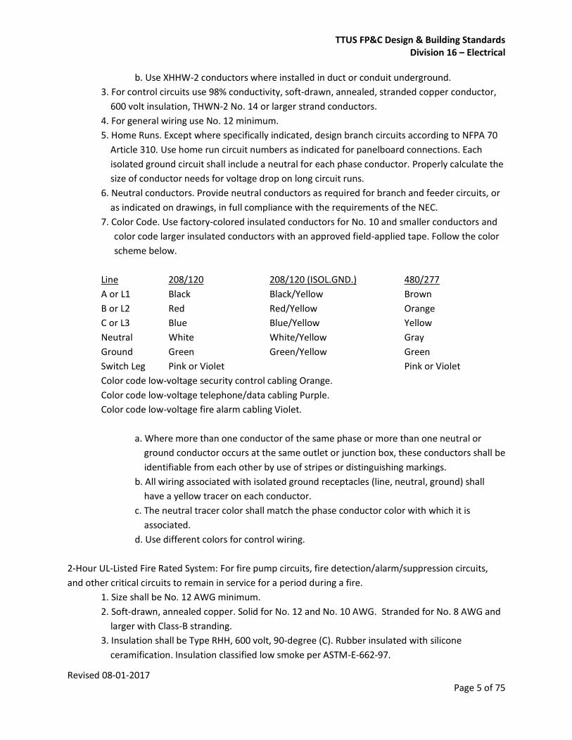
7. Color Code. Use factory-colored insulated conductors for No. 10 and smaller conductors and
color code larger insulated conductors with an approved field-applied tape. Follow the color
scheme below.
Line 208/120 208/120 (ISOL.GND.) 480/277
A or L1 Black Black/Yellow Brown
B or L2 Red Red/Yellow Orange
C or L3 Blue Blue/Yellow Yellow
Neutral White White/Yellow Gray
Ground Green Green/Yellow Green
Switch Leg Pink or Violet Pink or Violet
Color code low-voltage security control cabling Orange.
Color code low-voltage telephone/data cabling Purple.
Color code low-voltage fire alarm cabling Violet.
a. Where more than one conductor of the same phase or more than one neutral or
ground conductor occurs at the same outlet or junction box, these conductors shall be
identifiable from each other by use of stripes or distinguishing markings.
b. All wiring associated with isolated ground receptacles (line, neutral, ground) shall
have a yellow tracer on each conductor.
c. The neutral tracer color shall match the phase conductor color with which it is
associated.
d. Use different colors for control wiring.
2-Hour UL-Listed Fire Rated System: For fire pump circuits, fire detection/alarm/suppression circuits,
and other critical circuits to remain in service for a period during a fire.
1. Size shall be No. 12 AWG minimum.
2. Soft-drawn, annealed copper. Solid for No. 12 and No. 10 AWG. Stranded for No. 8 AWG and
larger with Class-B stranding.
3. Insulation shall be Type RHH, 600 volt, 90-degree (C). Rubber insulated with silicone
ceramification. Insulation classified low smoke per ASTM-E-662-97.
TTUS FP&C Design & Building Standards Division 16 – Electrical
Revised 08-01-2017 Page 6 of 75
4. Sheath shall be nonmetallic, moisture, sunlight and corrosion resistant, and flame retardant,
specifically approved for this application.
5. Conduit:
a. Two-hour fire-rated systems shall be installed in rigid metallic conduit as required to
conform to UL-listing. Provide rigid metallic conduit system for installation of 2-hour
fire-rated conductors where circuits pass through and into the boundaries of the
building.
b. Rigid Galvanized Steel Conduit (RGS), size three-quarter inch or larger. Use RGS
conduit, unless noted otherwise on drawings.
6. Use Electrical Metallic Tubing (EMT), size three-quarter inch or larger, for 2-hour fire-
rated systems only where approved in writing by the Engineer and the Owner.
7. Electrical circuit protective system shall be approved for vertical installation, including cable
support mechanism.
8. Electrical circuit protective system shall be approved with a fire rated seal used to prevent
smoke from entering unwanted areas.
9. For elevator controller supply conductors, emergency feeder circuits, and other circuits where
indicated on Drawings, where specified, or where required per NEC-700.9(D)(1).
10. Listings:
a. UL 2196. Exposure up to 1850 degrees (F) with immediate application of water
hose stream and maintenance of full utilization voltage and electrical load
throughout the duration of the test.
b. UL 83.
c. UL Fire Resistance Directory:
1. Electrical Circuit Protective system (FHIT) No. 27, 25, or accepted substitution.
d. 2-hour fire-rated circuit system shall be UL listed with steel pullbox, steel conduit
body, conduit couplings, ground wire, pulling lubricant, and supports, in accordance
with the applicable UL electrical circuit protective system (FHIT).
1. Where 2-hour fire-rated circuit system UL-listing does not include pullbox or
conduit body, provide 2-hour fire-rated construction for termination of
raceway at pullbox or conduit body.
2. Where 2-hour fire rated circuit system UL-listing does not include ground
wire provide ground wire of same construction as ungrounded circuit
conductors.
3. Where 2-hour fire rated circuit system UL-listing does not include pulling
lubricant, provide UL-listed 2-hour fire rated circuit system with conductors
suitable for installation without pulling lubricant.
11. Other UL-listed two-hour fire rated circuit protective systems may be used where approved
by the NEC and where proposed substitutions are accepted in writing by the Design
Professional and the Owner. Refer to Division 01 requirements for submittals and
substitutions.
1. Mineral-insulated (MI) cable per NEC-332.
TTUS FP&C Design & Building Standards Division 16 – Electrical
Revised 08-01-2017 Page 7 of 75
2. UL-listed fire-wrapping for conductors rated 600 volt and below.
3. Concrete encasement.
12. Where indicated on plans or specifications, provide UL-Listed 2-Hour Fire-Rated system for
circuit(s) rated 600 volts or below.
13. Install 2-hour UL-Listed, fire-rated system in rigid galvanized steel (RGS) conduit, unless
otherwise noted on drawings. Where accepted in writing by Engineer and Owner, 2-hour
UL-Listed fire-rated system may be installed in electrical metallic tubing (EMT). Refer to
raceway requirements.
14. Install 2-hour UL-Listed fire-rated system in accordance with manufacturer’s instructions,
the requirements of the NEC and UL.
15. Substitutions. Where substitution of alternate 2-hour UL-Listed fire-rated systems are
accepted in writing by the Engineer and the Owner, provide alternate systems in accordance
with manufacturer's instructions and the requirements of the NEC, UL Listing, NFPA, and
Owner's standards. Alternate systems include, but are not limited to, mineral-insulated (MI)
cable, concrete encasement, and fire-wrapping of designated cable and conduit systems.
Wiring Connections and Terminations:
1. Provide factory-fabricated, compression-type metal connectors of the size, rating, material,
type and class as indicated for each service. Where not indicated, provide proper selection as
required to comply with installation requirements and with NEC standards. Select from only
following types, classes, kinds and styles:
2. Type:
a. Solderless pressure connectors.
b. Insulated spring wire connectors with plastic caps for 10 AWG and smaller.
c. Insulated ring- or spade-type compression terminals for termination of stranded
conductors at wiring devices and terminal blocks.
d. Crimp.
e. Threaded.
3. Class: Insulated.
4. Material: Copper (for CU to CU connection).
5. Style:
a. Insulated terminals. Use ring-terminal for control wiring. Use flange (fork) spade
compression terminal for termination of stranded conductors at wiring devices,
including ground connection.
b. Split bolt-parallel connector.
c. Pigtail connector.
d. Pre-insulated multi-tap connector: NSI Industries “Polaris” series, Ilsco Corp. “Clear
Tap” type PST, Burndy /FCI “Unitap”, or accepted substitution.
6. Install splices, taps and terminations which have both mechanical strength and insulation
equivalent to or better than the conductor. Make splices, taps and terminations to carry full
ampacity of conductors without perceiving temperature rise.
TTUS FP&C Design & Building Standards Division 16 – Electrical
Revised 08-01-2017 Page 8 of 75
7. Conductor splices and taps shall be made only in junction boxes or wireways, and shall be
accessible. Conductor splices and taps shall be kept to the minimum necessary to completely
wire each branch circuit and feeder as indicated on the drawings. Conductor splices and taps
shall generally be made and installed above grade.
8. Splices below grade shall be in water-tight handholes, pull boxes, or manholes approved for
this use, and shall be made watertight with epoxy resin type splicing kits similar to 3M
Scotchcast.
Under no circumstances, however, shall the Contractor make or install splices or taps below
grade without having first secured the written approval of the Owner's duly authorized
representative.
9. Use splice, tap and termination connectors which are compatible with the conductor
material. Use compression (pressure-type, full circumferential) lugs or connectors for
terminations or splices of all stranded conductors. Use ring-tongue type terminators on all
control wiring. Use flanged spade type terminators for termination of stranded conductors at
wiring devices, including ground connection. Connect all conductors No. 6 AWG and larger
using high conductivity, wrought copper, color-keyed compression connectors.
10. Crimping tools, dies, and connectors shall be products of the same manufacturer.
11. Electricians installing compression connectors must have current certification for using
crimping tool with which they are working.
12. Thoroughly clean wires before installing lugs and connectors.
13. Terminate spare conductors with electrical tape.
14. Make grounding (earth) conductor approximately 2 inches longer than the ungrounded
(phase) and grounded (neutral) conductors at both ends. This extra length of grounding
conductor shall be provided at each splice and termination point to ensure the continuity of
the grounding conductor in the event that splices or terminations of the phase or neutral
conductors inadvertently separate under strain.
15. Contractor shall provide torque at each lug, terminal bolt/nut, per manufacturer
recommendations.
Armored Cable:
1. Size. No. 12 AWG minimum.
2. Construction:
a. Conductor. Soft-drawn, annealed copper. Solid for No. 12 and No. 10 AWG.
Stranded for No. 8 AWG and larger.
b. Insulation. THHN.
c. Armor. Flexible, spiral-wound, square-locked, hot-dipped galvanized steel strip or
aluminum strip (as fixture whip for luminaires only).
d. Sheath. Nylon or plastic outer sheath between insulated conductors and armor.
3. Use. For branch circuits only where accepted in writing by the Engineer and by the Owner’s
Representative for each specific location and application proposed for installation by the
Contractor.

TTUS FP&C Design & Building Standards Division 16 – Electrical
Revised 08-01-2017 Page 9 of 75
4. Listing. UL 4, type ACT HH.
5. Install armored cable in accordance with NEC Article 333. Do not install armored cable in
thermal insulation. Use fittings specifically designed for armored cable.
6. Obtain permission in writing from the Owner and from the Design Professional prior to using
or installing armored cable.
Provide factory-wrapped water-proof flexible barrier material for covering wire and cable wood reels,
where applicable; and weather resistant fiberboard containers for factory packaging of cable, wire and
connectors, to protect against physical damage in transit. Damaged cable, wire or connectors shall not
be used and shall be removed from project site. Store cable, wire and connectors in their factory-
furnished coverings in a clean, dry indoor space elevated above grade, which provides protection against
the weather and sunlight.
Install electrical cable, wire and connectors as indicated, in accordance with the manufacturer's written
instructions, the applicable requirements of NEC and as required to ensure that products serve the
intended functions.
Select conductors on the basis of their purpose and UL listing:
1. Generally, use types THHN/THWN-2 in building interiors and other dry locations.
2. Outdoors and underground in raceways, use type XHHW.
3. Conductors subject to abrasion, such as in lighting poles, shall be type THHN/THWN-2.
Neatly and securely bundle or cable all conductors in an enclosure using nylon straps with a locking hub
or head on one end and a taper on the other.
Torque conductor connections and terminations to manufacturers recommended values.
Perform continuity test on all power and equipment branch circuit conductors. Verify proper phasing
connections and phase rotation, where applicable.
Conductors may be run in parallel on sizes 1/0 AWG to 750 kcmil inclusive, provided all paralleled
conductors are the same material, size, length, and type of insulation. Except as otherwise shown on
drawings, no more than three line conductors and on neutral conductors may be run in one circuit, and
they shall be arranged and terminated to ensure equal division of the total current between all
conductors connected in parallel. Where parallel connection is contemplated, obtain approval from the
Owner's representative and Engineer prior to installation.
Prior to final acceptance, make voltage, insulation, and load tests necessary to demonstrate to the
Engineer and to the Owner's Representative the satisfactory installation and proper performance of all
circuits.

TTUS FP&C Design & Building Standards Division 16 – Electrical
Revised 08-01-2017 Page 10 of 75
Electrical Service Electrical service will be provided by Lubbock Power and Light with a utility transformer. The secondary
voltages typically available are 480Y/277V 3-phase, 4 wire; and/or 208Y/120V, 3-phase, 4 wire.
Schedule power outages to avoid interference with the Owner's activities. Obtain approval from Owner
at least 30 days prior to the requested outage. Demonstrate that all materials and equipment are on site
prior to making outage request. Provide to the Owner and Engineer a schedule showing sequence and
duration of all activities during the requested outage. At the Owner’s option, outages may be scheduled
at night or weekends. Outages and overtime incurred in support of outages shall be scheduled and
provided at no additional cost to Owner.
All electrical service charges shall be at the expense of the Contractor.
Grounding and Bonding Grounding Conductors
1. Material: copper.
2. Equipment Grounding Conductors: Insulated with green-colored insulation.
3. Isolated Ground Conductors: Insulated with green-colored insulation with yellow stripe. On
feeders with isolated ground, use colored tape, alternating bands of green and yellow tape to
provide a minimum of three bands of green and two bands of yellow.
4. Grounding Electrode Conductors: bare solid conductors.
5. Underground Conductors: Bare, tinned, solid, unless otherwise indicated.
6. Bare Copper Conductors:
a. Solid Conductors: ASTM B 3.
b. Assembly of Stranded Conductors: ASTM B 8.
c. Tinned Conductors: ASTM B 33.
7. Copper Bonding Conductors:
a. Bonding Cable: 28 kcmil, 14 strands of No. 17 AWG copper, ¼" diameter.
b. Bonding Conductor: No. 4 or No. 6 AWG, stranded copper conductor.
c. Bonding Jumper: Bare copper tape, braided bare copper conductors, terminated
with copper ferrules.
d. Tinned Bonding Jumper: Tinned-copper tape, braided copper conductors,
terminated with copper ferrules.
8. Grounding Bus: Bare, annealed copper bars of rectangular cross section, with
insulators.
Connectors
1. Comply with IEEE 837 and UL 467; listed for specific types, sizes, and combinations of
conductors and connected items.
2. Bolted Connectors: Bolted-pressure-type connectors or compression type.

TTUS FP&C Design & Building Standards Division 16 – Electrical
Revised 08-01-2017 Page 11 of 75
3. Welded Connectors: Exothermic-welded type, in kit form, and selected per manufacturers
written instructions.
Grounding Electrodes
1. Ground Rods: Copper-clad steel.
2. Chemical Electrodes: Copper tube, straight or L-shaped, filled with nonhazardous chemical
salts, terminated with a 4/0 bare conductor. Provide backfill material recommended by
manufacturer.
Bonding Materials
1. Bonding lugs, bonding rings, and other bonding material installed as recommended
by manufacturer.
Application
1. Use only copper conductors for both insulated and bare grounding conductors.
2. Make connections to prevent galvanic action or electrolysis.
3. Exothermic-Welded Connections: Use for connections to structural steel and for
underground connections unless otherwise noted.
4. Grounding Bus: Install in electrical and telephone equipment rooms, in rooms housing service
equipment, and elsewhere as indicated.
5. Underground Grounding Connections: Use copper conductor, no. 2/0 AWG minimum. Bury
at least 24 inches below grade or bury 12 inches above duct bank when installed as part of
the duct bank.
Equipment Grounding Conductor Installation
1. Comply with NFPA 70, Article 250, for types, sizes, and quantities of equipment grounding
conductors, unless specific types, larger sizes, or more conductors than required by NFPA 70
are indicated.
2. Install insulated equipment grounding conductor with circuit conductors for the following
items, in addition to those required by NEC:
a. Feeders and branch circuits.
b. Lighting circuits.
c. Receptacle circuits.
d. Single-phase motor and appliance branch circuits.
e. Three-phase motor and appliance branch circuits.
f. Flexible raceway runs.
g. Armored and metal-clad cable runs.
4. Busway Supply Circuits: Install insulated equipment grounding conductor from the grounding
bus in the switchgear, switchboard, or distribution panel to equipment grounding bar
terminal on busway.
5. Computer Outlet Circuits: Install insulated equipment grounding conductor in branch-circuit
TTUS FP&C Design & Building Standards Division 16 – Electrical
Revised 08-01-2017 Page 12 of 75
runs from computer-area power panels or power-distribution units.
6. Isolated Grounding Receptacle Circuits: Install an insulated equipment grounding conductor
connected to the receptacle grounding terminal. Isolate grounding conductor from raceway
and from panelboard grounding terminals. Terminate at equipment grounding conductor
terminal of the applicable derived system or service, unless otherwise indicated.
7. Isolated Equipment Enclosure Circuits: For designated equipment supplied by a branch
circuit or feeder, isolate equipment enclosure from supply raceway with a nonmetallic
raceway fitting listed for the purpose. Install fitting where raceway enters enclosure, and
install a separate equipment grounding conductor. Isolate equipment grounding conductor
from raceway and from panelboard grounding terminals. Terminate at equipment grounding
conductor terminal of the applicable derived system or service, unless otherwise indicated.
8. Nonmetallic Raceways: Install an equipment grounding conductor in nonmetallic raceways
When called out for specialized equipment installations.
9. Air-Duct Equipment Circuits: Install an equipment grounding conductor to duct-mounted
electrical devices operating at 120 V and more, including air cleaners and heaters. Bond
conductor to each unit and to air duct.
10.Water Heater, Heat-Tracing, and Antifrost Heating Cables: Install a separate equipment
grounding conductor to each electric water heater, heat-tracing, and antifrost heating cable.
Bond conductor to heater units, piping, connected equipment, and components.
11.Signal and Communication Systems: For telephone, alarm, voice and data, and other
communication systems, provide No. 4 AWG minimum insulated grounding conductor in
raceway from grounding electrode system to each service location, terminal cabinet, wiring
closet, and central equipment location.
a. Service and Central Equipment Locations and Wiring Closets: Terminate grounding
conductor on a 1/4-by-2-by-12-inch grounding bus.
b. Terminal Cabinets: Terminate grounding conductor on cabinet grounding terminal.
12.Metal Poles Supporting Outdoor Lighting Fixtures: Provide a grounding electrode in addition
to installing a separate equipment grounding conductor with supply branch-circuit
conductors.
13.Common Ground Bonding with Lightning Protection System: Bond electrical power system
ground directly to lightning protection system grounding conductor at closest point to
electrical service grounding electrode. Use bonding conductor sized same as system
grounding electrode conductor, and install in conduit.
Ground Rod, Grounding Conductor, Bonding Equipment Installation
1. Ground Rods: Install at least three rods spaced at least one-rod length from each other and
located at least the same distance from other grounding electrodes.
a. Drive ground rods until tops are 2 inches below finished floor or final grade, unless
otherwise indicated.
b. Interconnect ground rods with grounding electrode conductors. Use exothermic
welds, except at test wells and as otherwise indicated. Make connections without
TTUS FP&C Design & Building Standards Division 16 – Electrical
Revised 08-01-2017 Page 13 of 75
exposing steel or damaging copper coating.
2. Grounding Conductors: Route along shortest and straightest paths possible, unless otherwise
indicated. Avoid obstructing access or placing conductors where they may be subjected to
strain, impact, or damage.
3. Bonding Straps and Jumpers: Install so vibration by equipment mounted on vibration
isolation hangers and supports are not transmitted to rigidly mounted equipment. Use
exothermic-welded connectors for outdoor locations, unless a disconnect-type connection is
required; then, use a bolted clamp. Bond straps directly to the basic structure taking care not
to penetrate any adjacent parts. Install straps only in locations accessible for maintenance.
4. Metal Water Service Pipe: Provide insulated copper grounding conductors, in conduit, from
building's main service equipment, or grounding bus, to main metal water service entrances
to building. Connect grounding conductors to main metal water service pipes by grounding
clamp connectors. Where a dielectric main water fitting is installed, connect grounding
conductor to street side of fitting. Bond metal grounding conductor conduit or sleeve to
conductor at each end.
5. Water Meter Piping: Use braided-type bonding jumpers to electrically bypass water meters.
Connect to pipe with grounding clamp connectors.
6. Bond interior metal piping systems and metal air ducts to equipment grounding conductors
of associated pumps, fans, blowers, electric heaters, and air cleaners. Use braided-type
bonding straps.
7. Bond each aboveground portion of gas piping system upstream from equipment shutoff
valve.
Raceways and Conduits Wiring Installation in Raceways
1. Wire and cable shall be pulled into clean, dry conduit.
2. Pull conductors together where more than one is being installed in a raceway.
3. Use UL listed pulling compound or lubricant, when necessary. Compound must not
deteriorate conductor and insulation.
4. Do not use a pulling means, including fish tape, cable or rope which can damage the raceway.
5. Install wire in raceway after interior of building has been physically protected from the
weather and all mechanical work likely to injure or damage conductors has been completed.
6. Line and load conductors of motor starters, safety disconnects, and similar devices shall not
be contained in the same conduit or raceway. Provide separate raceway for line and load
conductors of motor starters, safety disconnects, and similar devices.
Conduit and Fittings
1. Conduit fittings shall be designed and approved for the specific use intended. Conduit fittings,
including fittings for flexible conduit, shall have insulated throats or bushings. Rigid conduits
TTUS FP&C Design & Building Standards Division 16 – Electrical
Revised 08-01-2017 Page 14 of 75
shall have insulated bushings, unless grounding bushings are required by NEC Article 250.
Grounding bushings shall have insulated throats.
2. Rigid Metal Conduit.
a. Conduit. Rigid hot-dipped galvanized steel (RGS) conduit with zinc-coated threads and
an outer coating of zinc chromate.
b. Fittings. Threaded steel or malleable iron, either cadmium plated or hot-dipped
galvanized. Expansion fittings shall be OZ Type DX, or approved equal.
c. Use. For applications as indicated in NEC 2014 Art 344.
3. Electrical Metallic Tubing (EMT):
a. Conduit. Galvanized electrical steel tubing.
b. Fittings:
1. 1” and Smaller: Steel compression type, either cadmium plated or hot dipped
galvanized. Connectors shall have insulated throat bushings. Contractor can
use set-screw type connector in lieu of steel compression type fittings.
Contractor is responsible to ensure no dents in interior wall of conduit where
set-screw is acting force.
2. Larger than 2”: Double set screw, either cadmium plated or hot-dipped
galvanized.
3. Expansion fittings shall be OZ Type TX or approved equal.
c. Use. For applications as indicated in NEC 2014 Art 358.
4. Rigid Nonmetallic Conduit:
a. Conduit:
1. Schedule 40 polyvinyl chloride (PVC).
2. Schedule 80 polyvinyl chloride (PVC), where indicated on drawings or
required by electric utility company (AEP) service standards.
b. Fittings. Solvent weld socket type.
c. Temperature. Nonmetallic conduit and fittings shall be suitable for temperature
rating of conductor but not less than 90°C.
d. Use: For applications as indicated in NEC 2014 Art 352.
5. Flexible Metal Conduit:
a. Conduit. Spiral-wound, square-locked, hot-dipped galvanized steel strip.
Aluminum is not an approved material.
b. Fittings. One-screw and two-screw for 1-1/2 inches and larger, double-clamp steel
or malleable iron, either cadmium plated or hot-dipped galvanized.
c. Use. For applications as indicated in NEC 2014 Art 348.
6. Liquid-tight Flexible Steel Conduit:
a. Conduit. Single strip, continuous, spiral-wound, flexible square-interlocked,
double-wrapped steel, hot-dipped galvanized inside and outside, forming a smooth
internal wiring channel with a bonded, liquid-tight outer jacket of flexible polyvinyl
chloride (PVC). Aluminum is not an approved material.
b. Fittings. Compression type, malleable iron, with insulated throat, either cadmium

TTUS FP&C Design & Building Standards Division 16 – Electrical
Revised 08-01-2017 Page 15 of 75
plated or hot-dipped galvanized.
c. Use. For applications as indicated in NEC 2014 Art 350.
7. Liquid-tight Flexible Non-metalic Conduit:
a. Conduit, liquid-tight jacket of flexible polyvinyl chloride (PVC) jacket over rigid PVC
core.
b. Fittings. Compression type, malleable iron, with insulated throat, either cadmium
plated or hot-dipped galvanized.
c. Use. For applications as indicated in NEC 2014 Art 356.
8. Sealing Fittings. Where conduit sealing fittings are required, they shall be of malleable iron,
copper-free cast aluminum, ferroalloy, or other suitable construction. Provide wide fill fitting
to facilitate insertion of sealing compound. Provide fitting closures, unions, and adapters of
the same manufacturer that are compatible with the selected sealing fitting.
a. Orientation. Unless specifically noted otherwise, provide conduit sealing fittings
suitable for installation in both horizontal and vertical raceways.
b. Combination Drain/Seal Fitting. Where drain/sealing fittings are required, they shall
be of malleable iron construction with an internal drainage path which provides a
visual means to ensure that the compound chamber is properly filled. The installation
shall enable the drain/breather fitting and filler plug to be installed immediately after
the sealing compound is poured.
c. Finish. Hot dipped galvanized.
d. Compound. Provide sealing compound compatible with the specified sealing fitting,
and in compliance with the requirements of NEC-501.15(C).
e. Listing. UL 886.
Wireways
1. Material not less than 16-gage sheet steel.
2. Cross section dimensions not less than 4” by 4”.
3. Provide dividers to separate wiring of different signal types (e.g.: power, data,
communications, control, etc.).
4. Provide all sheet metal parts with a rust-inhibiting phosphatizing primer coating and finished
in gray enamel, minimum of two coats. All hardware shall be cadmium plated to prevent
corrosion.
5. Type:
a. Indoors. NEMA 1.
b. Outdoors. NEMA 4X.
Conduit, wireway, and other raceway systems shall not serve as branch circuit grounding conductors.
Minimum Trade Size:
1. General. 3/4 inch, except that 1/2-inch flexible metal conduit may be used in lengths not
exceeding 72 inches for tap conductors supplying luminaires (pre-manufactured fixture
whips)
TTUS FP&C Design & Building Standards Division 16 – Electrical
Revised 08-01-2017 Page 16 of 75
2. Below Grade, Direct-Buried, or Concrete-Encased; 1 inch.
Use rigid steel conduit (RGS) throughout the project except as permitted or specified below:
1. Use EMT in standard trade sizes in the following areas:
a. Interior walls or ceiling spaces.
b. Where exposed when installed more than 8 feet above finished floor in open work
areas, mechanical rooms or electrical rooms.
c. Conduit which enters or leaves the top of panelboards or enclosures may be EMT,
provided the top of the panelboards or enclosures are a minimum of 5 feet above
finished floor and such panelboards and enclosures are located in mechanical or
electrical rooms.
3. Below Grade:
a. Use RGS or rigid nonmetallic conduit.
b. All horizontal to vertical transitions shall be made using RGS elbows and RGS conduit
stub-ups. All RGS in-contact with earth shall be PVC wrapped.
c. Use direct-buried schedule 40 PVC conduit where installed below grade for
branch circuits, and feeder circuits as indicated on plans.
d. Separation from other below-grade utilities and systems. Twelve inches minimum.
Relaxation of this requirement must be approved in writing by the Owner’s
Representative.
4. Rigid Non-Metallic Conduit (PVC):
a. Non-metallic conduit installed above ground shall be approved in writing by the
Owner's representative and the Design Professional prior to installation. Use PVC
Schedule 80 where installed above ground or otherwise exposed.
5. Install flexible conduit connection such that vibrations are not transmitted to adjoining
conduit or building structure.
a. Install liquid-tight flexible metal conduit for connections to all electrical equipment
subject to vibration or movement, including dry-type transformers. Maximum length
72 inches; 36 inches for connection to dry type transformers. Provide liquid-tight
flexible metal conduit with proper liquid-tight fittings for exterior locations or in wet
areas.
b. Install flexible metal conduit (not liquid-tight) for connections to electrical equipment
located in a duct or plenum used for environmental air. Maximum length 48 inches.
c. Minimum size shall be 3/4-inch except for lay-in luminaires, where it may be 1/2-inch
flexible steel pre-manufactured fixture whips not exceeding 72 inches.
d. Chain-Hung Luminaires. Provide flexible steel conduit from a junction box directly
above the luminaire. Conduit length shall be such that the luminaire weight is not
borne by the conduit and does not cause excessive sag; 72 inches maximum.
e. Lighting Troffers. Provide 6 feet of flexible steel conduit for connection from recessed
troffer to a junction box mounted at the structure.

TTUS FP&C Design & Building Standards Division 16 – Electrical
Revised 08-01-2017 Page 17 of 75
Where conduit penetrates fire-rated walls and floors, provide pipe sleeve two standard sizes larger than
conduit. Coordinate with Division 7 to fire-seal penetrations of fire-rated walls and floors; pack void
around conduit with oakum and fill ends of sleeve with fire-resistive compound or provide mechanical
fire-stop fittings with UL listed fire-rating or seal opening around conduit with UL listed foamed silicone
elastomer compound equal to fire-rating of floor or wall.
Cable Trays Specify ladder type cable trays, in compliance with current applicable EIA/TIA standards for
communications pathways. Tray to be 6063-T6 aluminum extrusion with aluminum allow 2024
fasteners, fittings, and accessories. Basket type trays will only be permitted with FP&C PM permission.
Provide covers on tray where exiting the top of control cabinets, communication/data cabinets,
distribution panelboards and switchboards which covers vertical sections of tray and 90 degree bend.
Provide warning signs every 50 feet with 1/2 inch high black letters on yellow plastic with the following
wording:
WARNING! DO NOT USE CABLE TRAY AS
WALKWAY, LADDER, OR SUPPORT.
USE ONLY AS MECHANICAL SUPPORT
FOR CABLES AND TUBING!
Install cable trays, where shown, according to NEC 2014 Article 392 and NEMA requirements. Install
cable trays in accordance with manufacturer's written instructions and recommendations.
Automatic Transfer Switches Specify a UL 1008 factory-assembled automatic transfer switch which is electrically operated and
mechanically held in each direction, and which is true double-throw.
Provide switch in a UL listed, free-standing NEMA 12 enclosure suitable for floor mounting. Enclosure
shall provide wire bending space as required by NEC. The cabinet door shall be key-locking. Provide LED-
type switch position indicator lamps and power available lamps for both sources (4 total) on exterior
face of cabinet door.
Transfer switches shall be rated for continuous duty at 100 percent of rated current, in the specified
enclosure at rated temperature without de-rating. Transfer switches shall conform to the applicable
requirements of UL 1008 for emergency system total load. The automatic transfer switches shall be fully
rated to carry and protect all types of loads, inductive and resistive, without de-rating. Circuit breaker
type transfer switches are not acceptable.

TTUS FP&C Design & Building Standards Division 16 – Electrical
Revised 08-01-2017 Page 18 of 75
Transfer switch equipment shall have withstand and closing rating in RMS symmetrical amperes greater
than the available fault current at the distribution panelboard providing normal (utility) service to the
transfer switch. Series rating is not acceptable.
All pilot devices and relays shall be of the industrial type with self-cleaning contacts and rated 10
amperes, minimum.
Transfer switches shall be double throw, electrically and mechanically interlocked, and mechanically
held in both positions.
The contact assemblies shall be actuated by two non-fused electric operators or stored energy
mechanism and be energized only momentarily during transfer, providing inherently double throw
switching action, and connected to the transfer mechanism by a simple over-center type linkage.
Control power for all transfer operations shall be derived from the line side of the source to which the
load is being transferred.
Transfer switches shall be equipped with permanently attached manual operating handles and quick
break, quick make over center contact mechanisms suitable for safe manual operation under load. The
manual operator shall provide the same contact-to-contact transfer time as provided under normal
automatic operation to prevent possible flashovers from switching the main contacts slowly.
Transfer switches shall be of open-transition (break-before-make) design. Each transfer switch shall be
positively interlocked both mechanically and electrically to prevent simultaneous closing of both sources
under either automatic or manual operation. Main contacts shall be mechanically locked in position in
both normal and emergency positions. Provide transfer switch with delayed transition center-neutral
position and dual-motor operator mechanism for switching highly inductive loads. Each transfer switch
shall have a manual neutral position for load circuit maintenance. A transfer switch position indicator
shall be visible from the front of the switch to show to which source the transfer switch is connected.
Main switch contacts shall be high pressure silver alloy. Contact assemblies shall have arc chutes for
positive extinguishment. Arc chutes shall have insulating covers and arc barriers to prevent inter-phase
flashover.
All three-phase four-wire transfer switches used on system with ground fault equipment shall be true
four-pole switched neutral type, with neutral pole fully rated and connected to a common, insulated
shaft. The fourth (neutral) pole contacts shall be identical construction as, and operate simultaneously
with, the main power contacts. Add on or overlapping neutral contacts are not acceptable.
Where a solid neutral is indicated, provide a neutral bar with the same ampere capacity as the ampere
rating of the switch.
Drawout Mechanism (as required for critical circuits):
TTUS FP&C Design & Building Standards Division 16 – Electrical
Revised 08-01-2017 Page 19 of 75
1. Provide transfer switches with drawout mechanism to allow easy access for preventative
maintenance, testing or inspection. The drawout mechanism shall provide visual indication of
the position of the switch (i.e., Connected, Disconnected, Withdrawn) during the drawout
operation.
2. Provide transfer switch with a true drawout configuration which does not require
disconnection of any electrical or mechanical devices by personnel performing maintenance
upon and/or operation of the switch. Provide the automatic transfer switch with rollers or
casters to allow removal from enclosure by simply rolling out the unit.
Make transfer switch suitable for busway and/or conduit & wire connection to normal source,
emergency source, and load terminals as indicated on construction drawings and other applicable
contract documents. Make transfer switch suitable for top entry, bottom entry, or both as indicated on
construction drawings and other applicable contract documents.
Terminal blocks shall conform to NEMA ICS 4. Terminal facilities shall be arranged for entrance of
external conductors from the top or bottom of the enclosure.
Automatic Solid State Controller:
1. Controller shall be solid state and designed for a high level of immunity to power line surges
and transients, demonstrated by test to IEEE Standard 587. The controller shall have optically
isolated logic inputs, high isolation transformers for AC inputs, and relays on outputs.
2. The controller shall be equipped with self diagnostics, which performs periodic checks of the
memory, input/output (I/O), and communication circuits, with a watchdog/power fail circuit.
3. The controller shall be accurate to within 1 percent of full-scale value for measured
parameter. Voltage and current for all phases shall be sampled simultaneously to assure high
accuracy in conditions of low power factor or large waveform distortions.
4. Voltage sensors shall allow for adjustment to sense partial loss of voltage on any phase.
5. Automatic controls shall signal the engine generator set to start upon signal from normal
source sensors indicating loss of normal source. Battery voltage starting contacts shall be gold,
dry type contacts factory-wired to a field wiring terminal block.
6. The switch shall transfer when the emergency source reaches the set point voltage and
frequency.
7. The controller shall be capable of storing records in memory for access either locally or
remotely for up to 100 events. The reports shall include date, time and a description of the
event, and shall be maintained in a non-volatile memory.
8. If the controller is supplied with an automatic exercise feature (engine start, power transfer,
and cool down/shut down) this feature shall be disabled. TTU employs personnel to maintain
all engine/generator sets on campus.
TTUS FP&C Design & Building Standards Division 16 – Electrical
Revised 08-01-2017 Page 20 of 75
Factory and field test the complete automatic transfer switch assembly to ensure proper operation and
compliance with the requirements of this specification and with UL 1008, Automatic Transfer Switches.
Provide a copy of the factory and field test report to the Owner.
Specify to provide the services of the manufacturer’s factory-trained representative(s) on-site for testing
and start-up of the automatic transfer and switches, and associated components of the emergency
electrical distribution system. Verify data communication and functionality of interface with Energy
Management System, HVAC / DDC controls, remote devices, and engine-generator set.
Provide, at no cost to the Owner, on-site training for Owner's designated personnel in the construction,
operation, maintenance, troubleshooting and repair of the automatic transfer switch. Formal training
for the operation and maintenance of all equipment and systems specified herein shall be given by
factory trained and certified personnel.
Electrical Generating Plant This Section specifies the furnishing, installation, and acceptance testing of a complete and operable
packaged electric generating plant for standby service. Include all devices and equipment specified
herein, as shown on the drawings, or required for the service. Equipment shall be new, factory tested,
and delivered ready for installation. Equipment shall meet applicable requirements of NFPA-110, Type
10 and EPA Tier 3 emissions requirements for non-road diesel engines. Cummins should be the Basis of
Design.
Provide a no deductible warranty for products against defects in materials and workmanship for a five-
year or 1500-hour period from the start-up date, per the manufacturer’s Basic Extended Coverage
Limited Warranty.
The supplier shall be the manufacturer's authorized distributor, who shall provide initial start-up
services, conduct field acceptance testing, and warranty service. The supplier shall have 24-hour service
availability and factory-trained service technicians authorized to do warranty service on warrantable
products. The supplier shall have locally available service technicians. Locally available shall be
understood as available onsite within 2 hours’ notice, 24 hours per day, and 365 days per year.
Provide a complete, packaged, diesel engine-electric generating plant which is prewired, pre-piped,
assembled and aligned on a single skid-type base. Make the packaged system of new, unused
equipment of the manufacturer's latest design. Include necessary instruments, devices, switches, and
other appurtenances for proper operation of the unit. Supply steel safety guards around all external
rotating parts. Provide a unit on which adjustments, repairs and normal maintenance are possible
without the use of special tools. Provide an overall, weatherproof housing as further described in this
section. The Contractor will be responsible for the proper performance of the complete unit and support
systems. Transition time from the instant of failure of the normal power source to the generator source
shall not exceed 10 seconds per NEC 700, Life Safety Code (LSC, NFPA 101) and NFPA 110.

TTUS FP&C Design & Building Standards Division 16 – Electrical
Revised 08-01-2017 Page 21 of 75
Provide a stationary, liquid-cooled, full diesel, compression ignition engine, either naturally aspirated or
turbocharged, with forged steel crankshaft and connecting rods. The cylinder block shall be cast iron
with a minimum of two valves per cylinder. Supply a unit suitable for operation on No. 2 diesel fuel oil.
Direct-injection diesel engine meeting the requirements of this Section shall be acceptable upon review
of submittal data.
Provide an engine with brake horsepower, at minimum tolerance level, not less than 10 percent greater
than required to drive the generator at full load rating, including losses, and with all accessories
attached
An electronic governor system shall provide automatic isochronous frequency regulation. Speed must
not exceed 10 rpm above generator rated speed. Provide governor of the full hydraulic type, Woodward
EGP3 with a 2301A electronic speed controller, or an accepted substitution, to maintain frequency
stability of any constant load, including no load, within plus or minus 1/4 percent, and to maintain
frequency regulation between no load steady-state and full load steady-state within plus or minus 1/4
percent. Speed droop must be isochronous from no load to full load.
Specify standard wet-cell lead acid batteries or absorbed glassmatt (AGM) sealed valve-regulated lead-
acid (VRLA) batteries. Gel-cell batteries using a gelled electrolyte in a sealed battery case are NOT
acceptable.
Specify a static, solid-state type battery charger unit which automatically controls the charge rate and
which has an adjustable charging rate. Include a charging rate ammeter, a voltmeter, and a manual
reset, thermal overload circuit breaker to protect the rectifier assembly and transformer. Size charger to
recharge the battery from a fully discharged state to a fully charged state within 24 hours or less.
Arrange charging system such that charging occurs from the normal source when the generator is shut
down, and from the generator when the generator unit is supplying emergency power.
Specify closed-loop, liquid coolant system complete with unit-mounted radiator, fan, coolant manifold,
coolant expansion chamber (overflow tank), temperature control valve, and engine-driven coolant
circulating pump.
Specify an engine-mounted, corrosion-resistant, thermostatically controlled coolant heater(s) for each
engine. Heater voltage shall be as shown on the project drawings. The coolant heater shall be
UL499 listed and labeled.
Specify a high degree, critical-rated silencer (muffler) capable of passing rated engine exhaust gases with
maximum silencing capacity.

TTUS FP&C Design & Building Standards Division 16 – Electrical
Revised 08-01-2017 Page 22 of 75
Specify fuel tank to be tank-in-tank construction. Interstitial space shall have a fuel sensor to detect a
leak in the inner tank. Provide leak detection and monitoring system for the fuel tank. The alarm shall be
on the remote alarm panel. Fuel tank is to be sized for 12 hours of operation at maximum load.
Specify a direct-coupled, 4-pole, synchronous, low reactance, brushless-type generator (alternator) with
amortisseur windings, revolving field permanent magnet generator (PMG), exciter, single pre-lubricated
sealed bearing, air cooled by a direct drive centrifugal blower fan, and built-in static rectifier and
statically regulated torque matched excitation system with automatic voltage regulator.
Specify a factory-fabricated, -wired, and -tested microprocessor-based monitoring, metering, and
control system. The control system shall provide for operator interface, digital voltage regulation, digital
governing, protective functions, automatic starting, automatic unloading and cool down, automatic
shutdown, and communication of alarm and status signals.
The generator controller shall be capable of communicating all data, including alarm and trip data, in
ModBus RTU format to the digital power meter in the Generator Emergency Switchboard. Where the
controller does not incorporate or support ModBus communication, provide a ModBus gateway for
communication between the generator controller and the 480-volt Generator Emergency Switchboard
power meter.
At time of Owner's acceptance, provide one set of new, unused filters of each size and type required for
12 months of operation and maintenance. Provide filters in factory sealed containers or wrapping,
clearly labeled for ease of identification. Deliver filters to location as directed by Owner.
Equipment shall be warranted from defective workmanship or materials for a period of 2 years after
final acceptance.
Electrical Identification Electrical identification means, methods, materials and devices required to comply with ANSI C2, NFPA
70, NEC, and OSHA standards.
Raceway and Cable Labels
1. Feeder conduits: Provide adhesive labels, preprinted, flexible, self-adhesive vinyl with legend
over laminated with a clear, weather- and chemical-resistant coating.
2. Underground-Line Warning Tape: Permanent, bright-colored, continuous-printed, vinyl tape.
See TTU Operating Policies and Procedures for Underground marking installation.
a. Not less than 6 inches wide by 4 mils thick.
b. Compounded for permanent direct-burial service.
c. Embedded continuous metallic strip or core is not suitable for tracing and not
approved.
d. Printed legend indicating type of underground line.
3. Tape Markers: Vinyl or vinyl-cloth, self-adhesive, wraparound type with preprinted numbers
TTUS FP&C Design & Building Standards Division 16 – Electrical
Revised 08-01-2017 Page 23 of 75
and letters for all control wiring.
Nameplates and Signs
1. Safety Signs: Comply with 20 CFR, Chapter XVII, Part 1910.145.
2. Engraved Plastic Nameplates and Signs: Engraving stock, melamine plastic laminate,
minimum 1/16 inch thick for signs up to 20 sq. in and 1/8 inch thick for larger sizes.
a. Engraved legend with black letters on white face.
b. Punched or drilled for mechanical fasteners.
3. Fasteners for Nameplates and Signs: Self-tapping, stainless steel screws or No. 10/32,
stainless-steel machine screws with nuts and flat and lock washers.
Installation
1. Identification Materials and Devices: Install at junction boxes and other locations for most
convenient viewing without interference with operation and maintenance of equipment.
2. Lettering, Colors, and Graphics: Nameplates shall contain the panel designation, voltage,
phase, and the designation of “fed from (feed source)”.
3. Circuit Identification Labels on Boxes: Install labels externally.
a. Provide pre-painted junction box covers for conduit associated with fire suppression
circuits.
b. For power circuits, provide the circuit designation on the junction box cover of each
circuit contained in the box.
c. Identify normal power circuits and emergency power circuits.
4. Paths of Underground Electrical Lines: During trench backfilling, for exterior underground
power, control, signal, and communication lines, install continuous underground plastic line
marker located directly above line at 12 to 16 inches below finished grade.
5. Secondary Service, Feeder, and Branch-Circuit Conductors: Color-code throughout the
secondary electrical system.
Panelboards Enclosure shall be proper NEMA type as shown on the drawings:
1. NEMA 1:
a. Back box shall be galvanized steel for flush mounted branch circuit panelboards. Back
box shall have enamel electro-deposited finish over cleaned, phosphatized steel for all
other type panelboards.
b. Where power monitors or metering are specified on the Drawings, the manufacturer
shall cut the doors for field mounting of the unit. Refer to Power Metering section
for details.
2. NEMA 3R, 3S and 12:
a. Enclosure and doors shall have enamel electro-deposited finish over cleaned
phosphatized steel.

TTUS FP&C Design & Building Standards Division 16 – Electrical
Revised 08-01-2017 Page 24 of 75
b. Doors shall be gasketed and equipped with tumbler type vault lock and two trunk
latches where required by UL standard. Interior trim shall consist of four pieces, each
covering one gutter top, bottom and both sides.
Construct cabinets in accordance with UL 50. Use not less than 16-gauge galvanized sheet steel. Provide
a minimum 4-inch gutter wiring space on each side.
Contractor can provide panelboards with ratings 225A or 400A with more than 42 circuits in one
enclosure section up to a maximum of 84 circuits. Typical preferred manufacturers are Schneider
Electric and Eaton Corporation.
Apply a finish to cabinet, trim, and doors. Exterior and interior steel surfaces shall be cleaned and
finished with electrostatically applied "powder coat" thermoset enamel baked over a rust-inhibiting
phosphatized coating. Exterior finish color shall be manufacturer’s standard gray, ANSI 49 or ANSI 61.
Interior finish shall be per Architect’s schedule.
Provide breakers which are quick-make and quick-break on both manual and automatic operation. Use a
trip-free breaker which is trip indicating. Incorporate inverse time characteristic by bimetallic overload
elements and instantaneous characteristic by magnetic trip.
Provide circuit breakers with ground fault circuit interrupter (GFI or GFCI) trip feature as scheduled or
indicated on drawing, or per NEC requirement.
Provide electronic grade panelboards as scheduled on drawings to provide effective transient voltage
surge suppression, surge current diversion and high frequency noise attenuation in all electrical modes
for equipment.
For each panelboard, provide a steel directory frame mounted inside the door with a heat resistant
transparent face and a directory card for identifying the loads served. Prepare a neatly typed,
computer-generated circuit index/directory inside the front door of each branch circuit panelboard and
each distribution panelboard identifying each circuit as shown on Panel Schedule and electrical one-line
drawings
At the completion of the electrical system installation, check each phase of all panels under full load and
arrange so that all phases shall carry the same load as near as possible.
Siemens will only be allowed with the consent of TTU BMC.
Power/Electrical Monitoring Power metering system at switchgear shall be PowerLogic (or approved equal) that is compatible with
existing PowerLogic software.
TTUS FP&C Design & Building Standards Division 16 – Electrical
Revised 08-01-2017 Page 25 of 75
Contractor shall provide the following PowerLogic devices and associated hardware:
For Research, Laboratory, High Computing Processes Building:
Provide Powerlogic series PM8000 model METSEPM8240 (or approved equal) manufactured by
Schneider Electric. Contractor shall coordinate with Switchgear Manufacturer exact size of Current
Transformers (CT’s) and Power Transformers (PT’s).
General Provisions:
1. Setup parameters required by the PM shall be stored in nonvolatile memory and retained in the event of a control power interruption.
2. The PM instrument may be applied in four-wire wye, three-wire wye, three-wire delta, direct delta, and single-phase systems.
3. The PM instrument shall be fully supported by PM software.
Markings:
1. The PM instrument shall be CE marked and comply with the applicable EU directives.
2. The PM instrument shall be marked as compliant with the applicable UL standards.
Standards Compliance:
1. The PM instrument shall comply to the following safety/construction standards:
a. CAN/CSA C22.2 No. 61010-1.
b. CAN/CSA C22.2 No. 61010-2-030.
c. IEC 61010-1.
d. IEC 61010-2-030.
e. IEC 62052-11.
f. IEC 62052-31.
g. UL 61010-1.
h. UL 61010-2-030.
2. The PM instrument shall comply to the following electromagnetic immunity standards:
a. ANSI/IEEE C37.90.1 (all inputs tested).
b. IEC 61000-4-2 (electrostatic discharge [B]).
TTUS FP&C Design & Building Standards Division 16 – Electrical
Revised 08-01-2017 Page 26 of 75
c. IEC 61000-4-3 (radiated EM field immunity [B]).
d. IEC 61000-4-4 (electric fast transient [B]).
e. IEC 61000-4-5 (surge immunity [B]).
f. IEC 61000-4-6 (conducted immunity).
g. IEC 61000-4-7 (harmonics and interharmonics).
h. IEC 61000-4-8, (immunity to power frequency magnetic field).
i. IEC 61000-4-11 (immunity to voltage dips, short interruptions and voltage variations).
j. IEC 61000-4-12 (immunity to damped oscillatory waves).
3. The PM instrument shall comply to the following electromagnetic emission standards:
a. FCC Title 47 CFR Part 15 (Subpart B, Class B: Class B digital device, radiated emissions).
b. EN 55011 (radiated/conducted emissions, Group 1, Class B).
c. EN 55022 (radiated/conducted emissions, Class B).
d. ICES 003 (industry Canada, ICES Class B digital device, radiated/conducted emissions).
e. IEC 61000-3-2 (limits for harmonic currents emissions; equipment input current less than 16 amperes per phase).
f. IEC 61000-3-3 (limitation of voltage fluctuations and flicker in low voltage supply systems for equipment with rated current less than 16 amperes).
4. The PM instrument shall comply to the following measurement standards with third party compliance certification as noted:
a. ANSI C12.20, Class 0.2 (Tests 1-9, 11, 13, 14 for accuracy). Third party certified.
b. IEC 61000-4-30 Edition 2, Class S. Third party certified.
c. IEC 62053-22, Class 0.2S. Third party certified.
d. IEC 62053-23, Class 2S. Third party certified.
e. IEC 62053-24, Class 0.5S.
f. IEC / EN 61557-12.
5. The PM instrument shall comply to the following communications standards with third party compliance certification as noted:
TTUS FP&C Design & Building Standards Division 16 – Electrical
Revised 08-01-2017 Page 27 of 75
a.
b.
c.
d.
e.
EIA/TIA-485.
IEC 61850 (Edition 1). Third party certified.
IEEE 802.3 - 2012.
IEEE 1815-2012 (DNP3 - Distributed Network Protocol).
Modbus Interoperability.
Current/Voltage Inputs:
1. The PM instrument shall have no less than three (3) voltage inputs and four (4) current inputs.
2. The PM instrument in its standard configuration shall be able to accept voltages up to 347 VLN / 600 VLL (UL) and 400 VLN / 690 VLL (IEC) without using potential transformers.
3. The PM instrument shall be able to withstand 3300 volts AC RMS for 2 seconds without damaging the device.
4. The PM instrument shall support nominal current ratings of 1 ampere or 5 amperes, and an over current rating of 500 amperes for 1 second.
Control Power:
1. The PM instrument shall be able to accept a wide range of control power inputs the range of 90 V AC to 415 V AC +/- 10% (45 to 65 Hz), 90 V AC to 120 V AC +/- 10% (400 Hz) or 120 V DC to 300 V DC +/- 10% without need for a control power transformer.
2. The PM instrument shall have the ability to sustain operation through a control power outage of 10 cycles, minimum, and ensure any events resulting in a control power outage will be captured.
Mechanical:
1. PM instrument shall be available in multiple form factors for panel mounting with an integrated display, and for DIN rail mounting without a display or with a remotely mounted display.
2. The panel mount meter with integrated display shall mount in a ¼ DIN, 92 x 92 mm (3.622” x 3.622”), cut-out without the need for tools.
3. The DIN rail mount meter, without a display, shall mount on a TS35 (35mm x 7.5mm) DIN rail without the need for tools.
4. The remotely mounted display shall support mounting in a ¼ DIN, 92 x 92 mm (3.622” x 3.622”), cutout, and support mounting in a 30.5 mm round hole (M30 punch).
5. The panel mount meter and the remotely mounted display shall meet UL/NEMA Type 12 and IP54 installation criteria when properly installed.
TTUS FP&C Design & Building Standards Division 16 – Electrical
Revised 08-01-2017 Page 28 of 75
6. The power meter unit shall have removable connectors for voltage inputs, control power, communications, inputs, and outputs.
Environmental:
1. The PM instrument shall have an operating temperature rating of -25 to 70 ºC (-13 to 158 ºF).
2. The PM instrument shall be installable in environments up to 3000 meters (9843 feet), relative humidity of 5% to 95% non-condensing (to a maximum dewpoint of 37 ºC), pollution degree 2.
3. The PM instrument shall be fully compliant with RoHS European directive ensuring the product does not include any of the 6 substances stated in the directive.
4. The PM instrument shall be fully compliant with the REACH European regulation ensuring the product does not include any of the identified Substances of Very High Concern (SVHC).
5. The PM instrument manufacturer shall provide, on request, a Product Environmental Profile (PEP) that provides a list of material, a recycling rate and a calculation of eleven environmental impacts such as raw material, energy consumption, carbon footprint and damage to the ozone layer that spans the entire product life cycle, from manufacture to end of working life.
6. The PM instrument manufacturer shall provide, on request, an End of Life Instruction guide (EoLI) providing clear instructions for recycling and disposal of the PM instrument at the end of its working life.
Measured Values:
1. The PM instrument shall provide at a minimum the following voltage values:
a. Voltage L–L per-phase.
b. Voltage L-L three-phase average.
c. Voltage L–N per-phase.
d. Voltage three-phase average.
e. Voltage percent unbalanced.
2. The PM instrument shall provide at a minimum the following current values:
a. Current per phase.
b. Current neutral (measured).
c. Current three-phase average.
d. Current percent unbalanced.
TTUS FP&C Design & Building Standards Division 16 – Electrical
Revised 08-01-2017 Page 29 of 75
3. The PM instrument shall provide at a minimum the following power values:
a. Real power (per phase, three-phase total).
b. Reactive power (per phase, three-phase total).
c. Apparent power (per phase, three-phase total).
d. Power factor - true (per phase, three-phase total).
e. Power factor - displacement (per phase, three-phase total).
4. The PM instrument shall provide at a minimum the following energy values:
a. Accumulated energy (real kWh, reactive kVARh, apparent kVAh) (signed/absolute).
b. Incremental energy (real kWh, reactive kVARh, apparent kVAh) (signed/absolute).
c. Conditional energy (real kWh, reactive kVARh, apparent kVAh) (signed/absolute).
d. Energy by quadrant (real kWh, reactive kVARh, apparent kVAh).
5. The PM instrument shall be able to provide a minimum/maximum value for any measured parameter.
6. The PM instrument shall be capable of deriving values for any combination of measured or calculated parameter, using the following arithmetic, trigonometric, and logic functions:
a. Arithmetic functions; division, multiplication, addition, subtraction, power, absolute value, square root, average, maximum, minimum, RMS, sum, sum-of-squares, unary minus, integer ceiling, integer floor, modulus, exponent, PI.
b. Trigonometric functions; COS, SIN, TAN, ARCCOS, ARCSIN, ARCTAN, LN, LOG10.
c. Logic functions; =, =>, <=, <>, <, >, AND, OR, NOT, IF.
d. Thermocouple linearization functions; Type J, Type K, Type R, Type RTD, Type T.
e. Temperature conversion functions; C to F, F to C.
Demand:
1. The PM instrument shall be able to provide last completed interval demand, predicted demand, peak demand with date and time, and coincident demand values on multiple demand channels.
2. The PM instrument shall be able to perform multiple accepted demand calculation methods, including, but not limited to, block, rolling block, and thermal demand with user-programmable demand period lengths.
TTUS FP&C Design & Building Standards Division 16 – Electrical
Revised 08-01-2017 Page 30 of 75
3. The PM instrument shall support the synchronization of the demand interval using a digital input, a command via communications, or internal clock.
Accuracy:
1. The PM instrument shall meet ANSI C12.20 accuracy Class 0.2.
2. The PM instrument shall meet IEC 62053-22 accuracy Class 0.2S.
3. The PM instrument shall meet IEC 62053-24 accuracy Class 0.5S.
4. The PM instrument shall provide four-quadrant metering.
Sampling:
1. The PM instrument shall sample continuously at 256 samples per cycle.
2. The PM Instrument shall be able to perform sag/swell detection of voltage disturbances on a half-cycle basis, providing the duration of the disturbance, the minimum, maximum, and average value of the voltage for each phase during the disturbance. Disturbances less than one cycle in duration can be detected.
Memory:
1. The PM instrument shall have at least 384 MB of non-volatile memory for configuration settings, log data, events, waveform captures, web pages and documents. A minimum of an additional 10 MB of memory shall be available for user programmable data logging.
2. The PM instrument shall store critical internal and revenue data upon sudden power loss.
3. The PM instrument shall retain all data and configuration in non-volatile memory for 15 years without control power.
4. The PM instrument shall provide a real time clock (RTC) with battery backup that will provide ride-through of at least 7 years without control power once installed, 10 years in storage.
5. The PM instrument shall have a field installable battery for real time clock ride-through that can be installed without need to remove the instrument from the installation.
6. The PM instrument shall have a time-stamped event log with the following features:
a. Shall support at least 500 events.
b. The number of records in the log shall be programmable.
c. Each event shall be recorded with the date and time of the event, the cause and effect of the event, and the priority of the event.
TTUS FP&C Design & Building Standards Division 16 – Electrical
Revised 08-01-2017 Page 31 of 75
d. Events relating to setpoint activity, relay operation, and self-diagnostics shall be recorded in the event log.
e. Time stamps shall have a resolution of 1 millisecond.
f. Time stamps can be synchronized to within +/- 1 millisecond between devices through the use of GPS (Global Positioning Satellites) serial input or IRIG-B digital input.
g. Minimum event recording response time shall be 1/2 cycle (8.3 ms 60 hertz, 10 ms 50 hertz) for high speed events and 1 second for other events.
h. The priority of setpoint events shall be programmable.
7. The PM instrument shall be able to log any parameter in the meter, including, but not limited to, minimum/maximum and waveforms.
8. The PM instrument shall be capable of supporting a minimum of 50 independent data logs that support the following configuration options:
a. Recording method of Fill and Hold or First In First Out (FIFO).
b. Selection of up to 16 parameters per log.
c. Log data on an event or based on internal clock.
d. Ability to automatically fill gaps in data logs with a value of zero (0) or leave blank.
Alarming:
1. The PM instrument shall have the ability to support a minimum of 65 setpoint driven alarms evaluated once per second or once every ½ cycle, user configurable.
2. The PM instrument shall have the ability to support disturbance alarms for detecting voltage and current dips and swells on all monitored phases.
3. The PM instrument shall be able to generate an E-mail on an alarm condition.
4. The PM instrument shall have millisecond time stamp resolution on alarm entries.
5. The PM instrument shall be able to adjust alarm setpoints based on the alarm quantity (alarm setpoint learning).
a. The user shall be able to enable the PM instrument to learn the characteristics of normal operation of metered values and select alarm setpoints based on this data.
b. The quantities to be learned shall be user selectable, including, but not limited to, standard speed alarms, high speed alarms, and disturbance alarms.
TTUS FP&C Design & Building Standards Division 16 – Electrical
Revised 08-01-2017 Page 32 of 75
c. The user shall be able to configure this feature using one of two modes:
1) Manual: Once the learning is completed, the recommended values shall be stored for review and manual installation.
2) Automatic: Once the learning is completed, the recommended values shall be automatically installed and operational.
d. The learning period shall be user configurable from 1 to 365 days to ensure system stability prior to determining the recommended setpoints.
6. The PM instrument shall support consecutive high speed alarm conditions which shall trigger on a cycle-by-cycle basis with no delay time between events (i.e., no need for a rearming delay time between events).
7. The PM instrument shall be able to operate relays on alarm conditions.
8. The PM instrument shall be able to initiate data log captures on alarm conditions.
9. The PM instrument shall be able to control digital output relays using pulse mode or latch mode operation, for control and alarm purposes.
10. The PM instrument shall be able to combine any logical combination of any number of available setpoint conditions to control any internal or external function or event.
Communications:
1. The PM instrument shall be capable of supporting the following physical, communications methods simultaneously and independently:
a. Ethernet (dual-port, single network).
1)
2)
10/100 Base-TX (port 1).
10/100 Base-TX (port 2).
b. Ethernet switch.
1)
2)
10/100 Base-TX (port 1).
10/100 Base-TX (port 2).
c. Ethernet switch with RSTP (Rapid Spanning Tree Protocol).
1)
2)
10/100 Base-TX (port 1).
10/100 Base-TX (port 2).
TTUS FP&C Design & Building Standards Division 16 – Electrical
Revised 08-01-2017 Page 33 of 75
d. Serial.
1) RS-485.
2. The PM instrument shall support multiple concurrent Ethernet communication protocols over an Ethernet network at any one time:
a. IEC61850.
b. DNP 3.0 TCP/IP.
c. Modbus TCP/IP.
d. Modbus TCP/IP mastering of Ethernet devices.
e. ION TCP/IP.
f. Ethernet to serial line gateway.
g. FTP (file transfer).
h. HTTP (web interface).
i. NTP / SNTP (time synchronization).
j. SMTP (E-mail).
k. SNMP (network management with traps).
l. MV-90 compatibility
3. The PM instrument shall support any one of the following serial communications protocols on any one serial port at any one time:
a. Modbus:
1) Modbus RTU.
2) Modbus mastering of Serial RS-485 slaves.
b. DNP 3.0.
c. ION.
d. MV-90 compatibility.
4. The PM instrument shall be able to support at least 32 concurrent Modbus TCP/IP connections.
5. The PM instrument shall have a Modbus TCP/IP gateway to provide a network connection to Modbus serial devices connected to a serial port on the instrument.
TTUS FP&C Design & Building Standards Division 16 – Electrical
Revised 08-01-2017 Page 34 of 75
6. The PM instrument shall have the ability to read from and write to Modbus devices connected to a serial port on the instrument and on a common local area Ethernet network.
7. The PM instrument shall serve web pages with the following capabilities to:
a. Provide real-time and historical data views in both tabular and graphical formats.
b. Provide a histogram of harmonic data through the 63rd harmonic.
c. Provide an ITIC (CBEMA) and a SEMI E10 summary of voltage disturbances.
d. Provide a NEMA motor derating curve.
e. Provide a phasor diagram representation of the electrical connections to the meter.
f. Provide a summary of EN 50160 power quality data along with a pass / fail analysis.
g. Provide a graphical trend for voltage, average current, frequency and power demand along with a forecast of the next 4 points.
h. Support the ability to provide technical documents and drawings in PDF format.
i. Support user defined web pages containing data from the host meter as well as data from Modbus devices connected to a serial port on the instrument and on a common local area Ethernet network.
8. The PM instruments shall have two (2) Ethernet ports that support the following functions:
a. Automatically E-mail alarm notifications or scheduled system status updates. E-mail messages sent by the PM instruments shall be able to be received like any ordinary E-mail message.
b. Ability to push historical logs through the Ethernet communication port to a remote server based on a user defined schedule or an event.
c. Built in web pages in the PM instruments shall enable access to real-time values and basic power quality information using a current standard web browser. Basic configuration of the PM instruments shall also be able to be performed through the browser.
9. The PM instruments shall automatically provide E-mail notifications for alarms and system status updates based on user configuration.
10. The PM instrument shall have the ability to push historical logs through the Ethernet communication port to a remote server based on a user defined schedule or an event.
11. The PM instrument shall provide an IEC 61850 compliant communications interface with the following features:
a. Four (4) concurrent client connections.
TTUS FP&C Design & Building Standards Division 16 – Electrical
Revised 08-01-2017 Page 35 of 75
b. File based setup via FTP.
c. Network time sync via NTP.
d. Configurable reports, including, but not limited to, selectable dataset member and configurable dead band values.
e. Support four (4) buffered reports and twenty (20) unbuffered reports (one (1) buffered and five (5) unbuffered per client).
f. Map up to 16 analog and/or 16 digital calculated values for reporting in IEC 61850.
g. Fault capture data for three-phase voltage and current in COMTRADE format, including, but not limited to, the following:
1) Up to 225 COMTRADE fault capture files.
2) The files shall be downloadable via standard FTP client.
3) The device shall support client notification through IEC 61850 to signal when new fault captures have been created and are available (RDRE logical node).
h. The following logical nodes shall be supported in addition to LLNO and LPHD (mandatory):
1) MHAI; harmonics.
2) MMTR; metering.
3) MMXU; measurement.
4) MSQI; sequence and imbalance.
5) MSTA; metering statistics.
6) GGIO; the ability to view data from and control all I/O points in the meter.
7) RDRE; disturbance recorder function.
12. The PM instrument shall have the ability to announce its presence on a local network segment using Device Profile Web Services (DPWS) over IPv6 local addressing without user interaction. The instrument shall be viewable in a Microsoft™ Windows™ Windows Explorer window view of network devices as a link that will provide access to the instrument’s web interface.
I/O Options:
1. The PM instrument shall be capable of having 27 digital inputs capable of one (1) millisecond timing resolution.

TTUS FP&C Design & Building Standards Division 16 – Electrical
Revised 08-01-2017 Page 36 of 75
2. The PM instrument shall be capable of receiving unmodulated IRIG-B time synchronization protocol
through integrated digital inputs to ensure system wide time accuracy.
3. The PM instrument shall have a Form A digital output that shall support pulse output operation for kWh total, kWh imported, kWh exported, kVARh total, kVARh imported, kVARh exported, and kVAh values.
4. The PM instrument shall have an optical test output that is compliant with IEC 62052-11.
5. The PM instrument shall be capable of supporting up to four (4) field installable option modules to expand digital and analog I/O capabilities without need for additional control power sources.
6. The PM instrument shall be capable of having up to eight (8) Form C relays which shall be isolated for up to 3200 volts AC (2 seconds), with reinforced isolation rated for 300 V. Overvoltage Category II. The relays shall support maximum current of eight (8) amperes continuous for 250VAC or five (5) amperes continuous for 24 volts DC for 20,000 cycles (resistive load)
7. The PM instrument shall be capable of having up to sixteen (16) Analog inputs which shall be isolated and support inputs of four (4) to twenty (20) milliamps or zero (0) to twenty-four (24 volts) volts DC.
8. The PM instrument shall be capable of having up to eight (8) Analog outputs of four (4) to twenty (20) milliamps or zero (0) to ten (10) volts DC range
9. The PM instrument shall be capable of providing consumption and rate of usage information with user defined units of measure from pulse inputs to support metering of utilities such as water, air, gas, electricity and steam (WAGES).
Display:
1. The PM instrument shall have two (2) graphical color display options: an integral display and a remote mounted display.
a. The panel mounted PM instrument shall have an integral 320 x 240 pixel backlit color graphical LCD display, TFT, 2.8 inches (71 mm) by 2.1 inches (53 mm) .
b. The DIN rail mounted PM instrument shall have a remotely mounted 320 x 240 pixel backlit color graphical LCD display, TFT, 2.8 inches (71 mm) by 2.1 inches (53 mm).
c. The remote display shall be fully powered by and capable of communicating with the PM instrument.
d. The remotely mounted display shall be able to be located up 100 meters (330 feet) from the PM instrument and be powered through a standard Cat5/5e unshielded twisted pair cable.
e. The displays shall be suitable for NEMA / UL type 12 (IP 54) enclosures.
f. The remotely mounted display shall perform and function in the same manner as the integrated display.

TTUS FP&C Design & Building Standards Division 16 – Electrical
Revised 08-01-2017 Page 37 of 75
2. The PM instrument shall be capable of presenting all real-time parameters on the instrument’s display.
3. The PM instrument shall have a user-programmable custom display that shall be capable of displaying up to six (6) quantities on a single screen.
4. The PM instrument shall be capable of displaying advanced graphical representations of metering information, including, but not limited to, harmonic histograms, phasor diagrams, and bar graphs.
5. The PM instrument shall be able to display measurements in either IEC or IEEE formats.
6. The PM instrument display shall support multiple languages, including, but not limited to, English, French, Spanish, German, Italian, Portuguese, Russian, and Chinese.
7. The PM instrument shall be able to present the following display screens:
a. Numeric: Display one (1) parameter , one (1) parameter with timestamp, two (2) parameters, three (3) parameters, three (3) parameters with timestamp, or four (4) parameters at a time.
b. Event Log: Display recent events written to the PM instrument’s event log, including, but not limited to, diagnostic events.
c. Nameplate: Display information in a tabular format (default nameplates shall show Owner, and meter details).
d. Bar: Display up to three (3) real time numeric parameters along with their upper and lower extremes.
e. Histogram: Display harmonics content in histogram format, including, but not limited to, 2nd to 63rd harmonic, THD (total, even, odd); ability to select and display magnitude and angle for individual harmonics
f. Phasor: Display current and voltage phase information in a phasor diagram format, including tabular display of magnitudes and angles.
g. Inputs and Outputs: Display digital input and output status, and analog input and output values.
h. Alarm: Display a listing of active and historical alarms and events.
Field Configuration: The PM instrument shall be configurable as follows:
1. Provide voltage input scale, voltage mode (wye, delta, single-phase), current input scale, auxiliary input and output scales, and communications setup parameters that shall be configurable from the instrument’s display, or via web pages.
2. Basic parameters described above, plus additional setpoint and data log setup parameters may be programmed via the communications port using a PC.

TTUS FP&C Design & Building Standards Division 16 – Electrical
Revised 08-01-2017 Page 38 of 75
3. Custom configuration of operating parameters shall be possible through a graphical, flexible programming language.
4. The configuration of the device shall be done using programmable modules. The modules shall be linked together in an arbitrary manner to create arbitrary functionality. Some example module types include, but shall not be limited to, minimum, maximum, setpoint, digital input, and digital output.
5. Programming through a computer shall be secured by user ID and password.
6. Programming through the instrument’s display shall be secured by password.
7. Programmability shall be sectioned such that when the meter is sealed it shall still be configurable to an extent that does not affect the accumulation of revenue metering related data.
Power Quality:
1. Without the use of separate software, the PM instrument shall be able to measure power quality statistically in accordance with IEC 61000-4-30, Class S.
2. The PM instrument shall be certified by a third party as compliant with IEC 61000-4-30 Class S, Edition 2.
3. The PM instrument shall be certified by a third party as compliant with IEC 62586, PQI-S.
4. Without using separate software, the PM instrument shall determine statistical indicators of power quality parameters that shall include, but shall not be limited to dips and swells, harmonics, and frequency, in accordance with the EN 50160 standard.
5. Without the use of separate software, the PM instrument shall make available the statistical indicators of power quality provided by EN50160 on the instrument’s display, or via communications protocols such as ION, Modbus RTU, Modbus TCP/IP, or via web pages.
6. The PM instrument shall be capable of monitoring the value of any statistical indicator of power quality (present, predicted, average, or otherwise manipulated value) with an absolute or relative setpoint. When such setpoint is exceeded, an alert shall be issued via E-mail or pager, or control shall be enabled via a local interface to mitigation equipment or control systems through relays and analog or digital outputs.
7. The PM instrument shall support symmetrical components.
Waveform Capture:
1. The PM instrument shall be able to perform 256 samples per cycle waveform recording.
2. The PM instrument shall have twenty-one (21) programmable oscillographic waveform recorders. Each waveform recorder shall have the following features:
a. Able to record a digitized representation of any phase voltage or current signal with no dead time between such recordings, and the ability to trigger multiple such recordings in continuous succession, and at different resolutions simultaneously.
TTUS FP&C Design & Building Standards Division 16 – Electrical
Revised 08-01-2017 Page 39 of 75
b. Enabled and triggered manually or through internal operating conditions, including, but not limited to, periodic timer or setpoint activity.
c. Half-cycle triggering shall be supported for waveform recorders.
d. The number of records (depth) of each data recorder, and the overflow conditions (stop-when-full or circular) shall be programmable.
3. The PM instrument shall be able to record continuously to capture long duration waveforms. The duration of the waveform capture shall be limited by memory alone.
4. The PM instrument shall be able to determine (with a level of confidence) whether a disturbance event occurred upstream or downstream of the meter (disturbance direction detection).
High-Speed Data Logging:
1. The PM instrument shall be capable of recording high-speed data captures containing one (1) cycle RMS data updated every half (1/2) cycle.
2. The PM instrument shall be able to record seconds of high-speed data per data capture.
3. The PM instrument shall be able to initiate a high-speed data capture based on a setpoint condition, user programmed logical condition, or command received via communication.
4. The PM instrument shall be capable of capturing high-speed logs concurrently with a waveform capture.
Advanced Features:
1. The PM instrument firmware shall be field upgradeable.
2. Onboard meter clock shall be able to be paced by a choice of sources, including, but not limited to, GPS, Ethernet network (NTP/SNTP), power line, or internal clock.
3. The PM Instrument shall have multi-level security which shall support customized access for up to 16 users.
4. The PM instrument shall have revenue security capabilities, including, but not limited to, the following:
a. Password protected, no hardware lock, or
b. Password protected and hardware locked, or
c. The following data shall be protected from alteration when locked:
1) kWh and kVARh (import, export, net, and total).
2) kVAh (total).

TTUS FP&C Design & Building Standards Division 16 – Electrical
Revised 08-01-2017 Page 40 of 75
3) kW, kVAR, kVA demand ( block and sliding window).
4) kWh, kVARh, kVAh pulse outputs.
5. The PM instrument shall have selective conformal coating of its internal circuitry for increased isolation and to increase robustness of installations exposed to high degrees of humidity.
6. The PM instrument shall have provisions for creating periodic or non-periodic schedules for up to two (2) years. These schedules shall be used to perform the following functions:
a. Time of use (TOU).
b. Demand control.
c. Load scheduling.
d. Logging.
e. Periodic resetting.
7. The PM instrument shall provide a physical lock switch that will preserve all meteorological configuration values to ensure accurate and consistent energy metering.
8. The PM instrument shall provide the ability to secure its meteorological lock switch as well as all voltage and current inputs with tamper detectable wire seals.
9. The PM instrument shall have multiple tariffs and time-of-use (TOU) functionality to store and monitor up to twenty (20) years of seasonal rate schedules. The TOU feature shall allow four (4) seasons, four (4) day types (each one capable of at least eight (8) switch times, with a resolution of one (1) minute). The TOU feature shall support four (4) rate tariffs, and at least twelve (12) holidays per year, and shall allow periodic self-read capability.
10. The PM instrument shall support trending and forecasting of real-time data values with visualization via device generated web pages.
For General Classrooms, Residence Halls, and General Offices Building:
Provide Powerlogic series PM5000 model METSEPM5320 (or approved equal) manufactured by
Schneider Electric. Contractor shall coordinate with Switchgear Manufacturer exact size of Current
Transformers (CT’s) and Power Transformers (PT’s).
1. General Provisions– Common Features
All setup parameters required by the power meter shall be stored in nonvolatile memory and retained in
the event of a control power interruption.

TTUS FP&C Design & Building Standards Division 16 – Electrical
Revised 08-01-2017 Page 41 of 75
The power meter may be applied in single phase, three-phase, three or four-wire systems in WYE or
Delta mode
The power meter shall be capable of being applied without modification at nominal frequencies of 50 or
60Hz.
The power meter shall have a real time clock with battery back-up with at least 1 year ride through time
without external power.
2. Mechanical
The power meter unit shall have removable connectors for voltage inputs, control power,
communications, input and outputs.
The power meter unit shall be easily mounted in the pre-made cut-out without tools.
Power meter form factor shall be ¼ DIN with 92 x 92 mm (3.622” x 3.622”) cut-out and 96 x 96 mm
(3.78” x 3.78”) panel mount integrated display.
The power meter unit shall be DIN-rail mounted with RJ-25 port to connect an optional remote display.
The remote display shall be easily mounted in the pre-made cut-out without tools.
Remote display form factor shall be ¼ DIN with 92 x 92 mm (3.622” x 3.622”) cut-out and 96 x 96 mm
(3.78” x 3.78”) panel mount remote display.
The remote display shall meet NEMA Type 12 and IP52 ratings at a minimum when properly installed.
3. Sampling and Harmonic Resolution
The current and voltage signals shall be digitally sampled at a rate high enough to provide true rms
accuracy to the 31st harmonic (fundamental of 50/ 60 Hz). The power meter shall provide continuous
sampling at a minimum of up to 64 samples/cycle, simultaneously on all voltage and current channels in
the meter.
The current and voltage signals shall be digitally sampled at a rate high enough to provide true rms
accuracy to the 63rd harmonic (fundamental of 60 Hz). The power meter shall provide continuous
sampling at a minimum of up to 128 samples/cycle, simultaneously on all voltage and current channels
in the meter.
4. Current Inputs
0-10 amps with 5 amps nominal input from CT secondary.
The power meter may be applied in three-phase, three- or four-wire systems.
Residual current shall be calculated by vectorial addition of the phase currents.
TTUS FP&C Design & Building Standards Division 16 – Electrical
Revised 08-01-2017 Page 42 of 75
A fourth CT input shall be available to measure neutral or ground current.
5. Voltage Inputs
Nominal of 400 V L-N / 690 V L-L.
Maximum of 480 V L-N / 828 V L-L.
6. Control Power (Device)
The monitoring device control power shall be:
100-415 VAC L-N ±10% or 125-250 ± 20% VDC
110-480 ±10%, VAC or 125-250 ± 20% VDC..
7. Environmental Characteristics
Operating temperature range:
meter: -25 to 70 °C (-13 to 158 °F), display -20 to 70 °C (-4 to 158 °F)
Meter and remote display: -25 to 70 °C (-13 to 158 °F)
8. Accuracy
The power meter unit shall use four-quadrant metering. The power meter shall sample current and
voltage simultaneously without gaps with 64 samples per cycle (zero blind).
The power meter device shall comply with ANSI C12.20 Class 0.5 and IEC 61557-12 Class 0.5 for revenue
meters.
IEC 61557-12 Class 0.2 for revenue meters.
Accuracy for Active energy of the power meter shall be class 0.5S as per IEC 62053-22.
Class 0.2 as per IEC 62053-22 for revenue meters.
Accuracy for reactive energy of the power meter shall be class 2 as per IEC 62053-23 (reactive energy)
The power meter shall be compliant to EN50470-1 (MID)
No annual calibration shall be required to maintain this accuracy.
9. Input/Output
The power meter shall support 2 digital inputs for Demand Interval Synch Pulse, Time Synch Input,
Conditional Energy Control), and 2 mechanical relay outputs.
The power meter shall support 4 digital inputs for Demand Interval Synch Pulse, Time Synch Input,
Conditional Energy Control), and 2 solid state outputs.

TTUS FP&C Design & Building Standards Division 16 – Electrical
Revised 08-01-2017 Page 43 of 75
10. Output Relay Control
Relay outputs shall operate either by user command sent over the communication link, or in response to
a user defined alarm or event. The output relays will have normally open and normally closed contacts
and can be configured to operate in several modes: Normal contact closure, latched mode, timed
mode, end of power demand interval and energy pulse output.
11. Energy quantities
Cumulative quantities for real, reactive and apparent energies shall be stored in non-volatile memory.
The power meter shall allow to pre-set the energy quantity at any value within the register range via
communications, to match a unit being replaced in the field.
The power meter shall provide the user the ability to reset the cumulative energy quantities from the
display of the unit or via communications.
12. Logging
The power meter shall provide for onboard data logging. Each power meter shall be able to log data,
alarms and events, and waveforms (if applicable). Logged information to be stored in each Power Meter
include the following: Data logs, Min/Max log files of selected parameter values, Alarm logs for each
user defined alarm or event and Waveform log. The meters shall offer the following on-board
nonvolatile memory: 1.1MB
The power meter shall have onboard memory big enough to log 14 values every 15 minutes for 90 days
or 2 values for 60 days.
13. Alarming
Alarm events shall be user definable.
Setpoint driven alarm events shall be available for voltage/current parameters, input status, and end of
interval status. For each over/under metered value alarm, the user shall be able to define a pick-up,
drop-out, and delay.
The power meter shall have a minimum of 28 setpoint driven alarms, or 29 setpoint driven alarms, 4
digital alarms, 4 unary alarms, 10 boolean alarms and 5 custom alarms.
There shall be four alarm severity levels in order to make it easier for the user to respond to the most
important events first.
Historical alarms shall have a time stamping with 1 second accuracy. The meter’s real time clock shall be
able to synchronize using communications command.
Indication of an alarm condition shall be given on the front panel.

TTUS FP&C Design & Building Standards Division 16 – Electrical
Revised 08-01-2017 Page 44 of 75
Indication of an alarm condition shall be delivered by email and/or text message. Settings for email-on-
alarm shall be configurable via the meter web pages.
Indication of an alarm condition shall be delivered by SNMP Traps. Settings for SNMP shall be
configurable via the meter web pages.
14. Communications
The power meter shall communicate via serial RS-485 Modbus or Jbus protocol.
The power meter shall provide Ethernet communications using Modbus TCP at 10/100Mbaud using UTP.
The power meter shall provide two Ethernet ports to allow wiring from meter to meter as a daisy-chain.
The power meter shall have the capability to serve data over the Ethernet network accessible through a
standard web browser. The monitor shall contain default pages from the factory. The power meter shall
push logging information through Ethernet communication port.
The power meter shall have integrated gateway functionality, enabling the capability to connect via
Ethernet to downstream, serially-connected devices.
The power meter gateway shall have the capability to limit host meter and serial slave device access
with Modbus TCP/IP filtering.
The power meter shall have the capability to manage and monitor devices on the IP network via Simple
Network Management Protocol [SNMP].
The power meter shall have the capability to compose and send emails and/or text messages containing
alarm condition indication via Simple Mail Transfer Protocol [SMTP].
The power meter shall have the capability to synchronize with a known addressable time reference via
Simple Network Time Protocol [SNTP].
15. Display
The power meter display shall be backlit dot-matrix LCD for easy viewing, display shall also be anti-glare
and scratch resistant with a minimum of 128x128 pixels.
The power meter display shall be capable of allowing the user to view four values on one screen at the
same time. A summary screen shall also be available to allow the user to view a snapshot of the system.
The power meter display shall allow the user to select a date/time format.

TTUS FP&C Design & Building Standards Division 16 – Electrical
Revised 08-01-2017 Page 45 of 75
The power meter display shall allow configuration for IEC or IEEE visualization of quantities. (CM Device)
The remote display shall have an RJ-25 port for cable connection to the DIN mount transducer unit.
16. Firmware Upgrade
It shall be possible to field upgrade the firmware in the power meters to enhance functionality. These
firmware upgrades shall be done through the Ethernet or serial communication connection and shall
allow upgrades of individual meters or groups.
17. Measured Values
The power meters shall provide the following, true RMS metered quantities. In addition, the power
meters shall record and save in nonvolatile memory the minimum and maximum values of all listed
values since last reset. The power meters shall also record and save in nonvolatile memory the interval
minimum, maximum, and average of any of the values pre-defined over a user specified interval
18. Real-time readings
o Current (Per-phase, 3-Phase Avg, % Unbalanced)
o Neutral and Ground (4CTs)
o Voltage (L–L Per-phase, L-L 3-Phase Avg, L–N Per-Phase, 3-Phase Avg, % Unbalanced)
o Real Power (Per-phase, 3-Phase Total)
o Reactive Power (Per-phase, 3-Phase Total)
o Apparent Power (Per-phase, 3-Phase Total)
o Power Factor (True/Displacement)(Per-phase, 3-Phase Total)
o Frequency
o THD, thd, TDD (Current and Voltage), Neutral & ground current
o Individual harmonics up to the order of 15th
o Temperature (Internal Ambient)
o K-Factor (Per-Phase)
o Crest Factor (Per-Phase)
19. Energy Readings
o Accumulated Energy (Real kWh, Reactive kVARh, Apparent kVAh) (Signed/Absolute)
o Active Energy Delivered
o Reactive Energy Delivered
o Energy Total Consumption for water, air, gas, steam (WAGES) for external meters 20.
TTUS FP&C Design & Building Standards Division 16 – Electrical
Revised 08-01-2017 Page 46 of 75
20. Demand Readings
o Demand Current Calculations (Per-Phase, 3-Phase Avg, Neutral)- Present and Peak
21. Demand Calculations (3-Phase Total):
o Real Power
o Reactive Power
o Apparent Power
22. All power demand calculations shall use any one of the following calculation methods, selectable by
the user:
o Thermal demand using a sliding window technique.
o Block interval, with optional sub-intervals. Block methods available are Sliding, Fixed and
Rolling.
o Demand can be calculated using a Synchronization signal:
o Demand can be synchronized to an input pulse from an external source.
o Demand can be synchronized to a communication signal.
o Demand can be synchronized to the clock in the power meter
23. Power Analysis Values
o THD, thd – Voltage, Current (3-Phase, Per-phase, Neutral & Ground current)
o Power Factor (Per-phase, 3-Phase)
o Displacement Power Factor (Per-phase, 3-Phase)
o Fundamental Voltage, Magnitude and Angle (Per-phase)
o Fundamental Currents, Magnitude and Angle (Per-phase)
o Fundamental Real Power (Per-phase, 3-Phase)
o Fundamental Reactive Power (Per-phase)
o Harmonic Power (Per-phase, 3-Phase)
o Phase Rotation
o Unbalance (Current and Voltage)
o Harmonic Magnitudes & Angles (Per-phase)
Total Demand distortion factor (TDD)
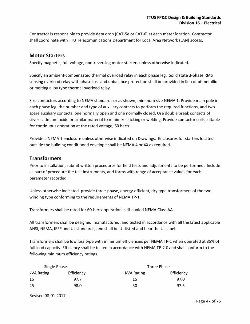
TTUS FP&C Design & Building Standards Division 16 – Electrical
Revised 08-01-2017 Page 47 of 75
Contractor is responsible to provide data drop (CAT-5e or CAT-6) at each meter location. Contractor
shall coordinate with TTU Telecomunications Department for Local Area Network (LAN) access.
Motor Starters Specify magnetic, full-voltage, non-reversing motor starters unless otherwise indicated.
Specify an ambient-compensated thermal overload relay in each phase leg. Solid state 3-phase RMS
sensing overload relay with phase loss and unbalance protection shall be provided in lieu of bi-metallic
or melting alloy type thermal overload relay.
Size contactors according to NEMA standards or as shown, minimum size NEMA 1. Provide main pole in
each phase leg, the number and type of auxiliary contacts to perform the required functions, and two
spare auxiliary contacts, one normally open and one normally closed. Use double break contacts of
silver-cadmium oxide or similar material to minimize sticking or welding. Provide contactor coils suitable
for continuous operation at the rated voltage, 60 hertz.
Provide a NEMA 1 enclosure unless otherwise indicated on Drawings. Enclosures for starters located
outside the building conditioned envelope shall be NEMA 4 or 4X as required.
Transformers Prior to installation, submit written procedures for field tests and adjustments to be performed. Include
as part of procedure the test instruments, and forms with range of acceptance values for each
parameter recorded.
Unless otherwise indicated, provide three-phase, energy-efficient, dry type transformers of the two-
winding type conforming to the requirements of NEMA TP-1.
Transformers shall be rated for 60-hertz operation, self-cooled NEMA Class AA.
All transformers shall be designed, manufactured, and tested in accordance with all the latest applicable
ANSI, NEMA, IEEE and UL standards, and shall be UL listed and bear the UL label.
Transformers shall be low loss type with minimum efficiencies per NEMA TP-1 when operated at 35% of
full load capacity. Efficiency shall be tested in accordance with NEMA TP-2.0 and shall conform to the
following minimum efficiency ratings.
Single Phase Three Phase
kVA Rating Efficiency KVA Rating Efficiency
15 97.7 15 97.0
25 98.0 30 97.5
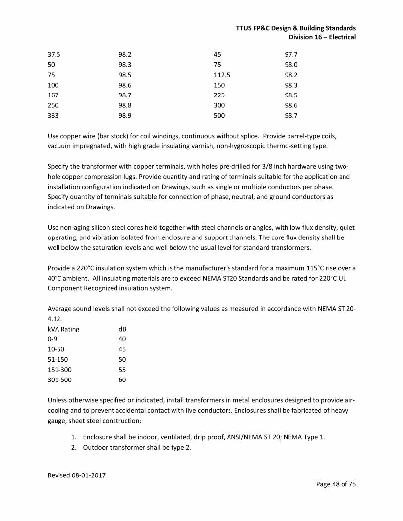
TTUS FP&C Design & Building Standards Division 16 – Electrical
Revised 08-01-2017 Page 48 of 75
37.5 98.2 45 97.7
50 98.3 75 98.0
75 98.5 112.5 98.2
100 98.6 150 98.3
167 98.7 225 98.5
250 98.8 300 98.6
333 98.9 500 98.7
Use copper wire (bar stock) for coil windings, continuous without splice. Provide barrel-type coils,
vacuum impregnated, with high grade insulating varnish, non-hygroscopic thermo-setting type.
Specify the transformer with copper terminals, with holes pre-drilled for 3/8 inch hardware using two-
hole copper compression lugs. Provide quantity and rating of terminals suitable for the application and
installation configuration indicated on Drawings, such as single or multiple conductors per phase.
Specify quantity of terminals suitable for connection of phase, neutral, and ground conductors as
indicated on Drawings.
Use non-aging silicon steel cores held together with steel channels or angles, with low flux density, quiet
operating, and vibration isolated from enclosure and support channels. The core flux density shall be
well below the saturation levels and well below the usual level for standard transformers.
Provide a 220°C insulation system which is the manufacturer's standard for a maximum 115°C rise over a
40°C ambient. All insulating materials are to exceed NEMA ST20 Standards and be rated for 220°C UL
Component Recognized insulation system.
Average sound levels shall not exceed the following values as measured in accordance with NEMA ST 20-
4.12.
kVA Rating dB
0-9 40
10-50 45
51-150 50
151-300 55
301-500 60
Unless otherwise specified or indicated, install transformers in metal enclosures designed to provide air-
cooling and to prevent accidental contact with live conductors. Enclosures shall be fabricated of heavy
gauge, sheet steel construction:
1. Enclosure shall be indoor, ventilated, drip proof, ANSI/NEMA ST 20; NEMA Type 1.
2. Outdoor transformer shall be type 2.
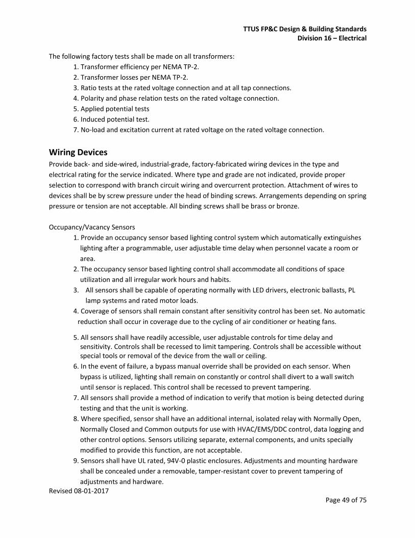
TTUS FP&C Design & Building Standards Division 16 – Electrical
Revised 08-01-2017 Page 49 of 75
The following factory tests shall be made on all transformers:
1. Transformer efficiency per NEMA TP-2.
2. Transformer losses per NEMA TP-2.
3. Ratio tests at the rated voltage connection and at all tap connections.
4. Polarity and phase relation tests on the rated voltage connection.
5. Applied potential tests
6. Induced potential test.
7. No-load and excitation current at rated voltage on the rated voltage connection.
Wiring Devices Provide back- and side-wired, industrial-grade, factory-fabricated wiring devices in the type and
electrical rating for the service indicated. Where type and grade are not indicated, provide proper
selection to correspond with branch circuit wiring and overcurrent protection. Attachment of wires to
devices shall be by screw pressure under the head of binding screws. Arrangements depending on spring
pressure or tension are not acceptable. All binding screws shall be brass or bronze.
Occupancy/Vacancy Sensors
1. Provide an occupancy sensor based lighting control system which automatically extinguishes
lighting after a programmable, user adjustable time delay when personnel vacate a room or
area.
2. The occupancy sensor based lighting control shall accommodate all conditions of space
utilization and all irregular work hours and habits.
3. All sensors shall be capable of operating normally with LED drivers, electronic ballasts, PL
lamp systems and rated motor loads.
4. Coverage of sensors shall remain constant after sensitivity control has been set. No automatic
reduction shall occur in coverage due to the cycling of air conditioner or heating fans.
5. All sensors shall have readily accessible, user adjustable controls for time delay and sensitivity. Controls shall be recessed to limit tampering. Controls shall be accessible without special tools or removal of the device from the wall or ceiling.
6. In the event of failure, a bypass manual override shall be provided on each sensor. When
bypass is utilized, lighting shall remain on constantly or control shall divert to a wall switch
until sensor is replaced. This control shall be recessed to prevent tampering.
7. All sensors shall provide a method of indication to verify that motion is being detected during
testing and that the unit is working.
8. Where specified, sensor shall have an additional internal, isolated relay with Normally Open,
Normally Closed and Common outputs for use with HVAC/EMS/DDC control, data logging and
other control options. Sensors utilizing separate, external components, and units specially
modified to provide this function, are not acceptable.
9. Sensors shall have UL rated, 94V-0 plastic enclosures. Adjustments and mounting hardware
shall be concealed under a removable, tamper-resistant cover to prevent tampering of
adjustments and hardware.

TTUS FP&C Design & Building Standards Division 16 – Electrical
Revised 08-01-2017 Page 50 of 75
Wall Switch Timers
1. Provide a programmable digital time switch where indicated on drawings to turn lights off
after a preset time delay.
2. Control circuitry shall employ zero crossing relay closure to increase the relay life, protect
from the effects of inrush current, and increase sensor longevity.
3. Time switch shall be a 3 wire, completely self-contained control system that replaces a
standard wall box toggle-type switch. Time switch shall have a ground wire for safety. Time
switch shall be compatible with all electronic ballasts, compact fluorescent lamps, motor
loads, and other inductive loads. Switching mechanism shall be a latching air gap relay. Triac
and other harmonic generating devices shall not be allowed as the output or switching device
of the time switch.
4. Time scroll feature shall allow manual overriding of the preset time-out period. Selecting time
scroll ON shall allow time-out period to scroll up throughout the timer possibilities to the
maximum. Time scroll OFF shall allow time-out period to scroll down to minimum.
5. Time switch shall have the option for a one-second light flash warning at one minute before
timer runs out.
6. Time switch shall have the option for a beep warning that shall sound every 5 seconds once
the time switch countdown reaches one minute.
7. Time switch shall have manual feature for timer reset where pressing the ON/OFF switch for
more than 2 seconds resets the timer to the programmed time-out period.
8. Time switch shall be capable of operating as an ON/OFF switch.
9. Time switch shall have an electroluminescent backlit liquid crystal display which shows the
timer countdown.
10. Time switch shall fit behind a decorator style faceplate.
11. Settings shall be selected by either a concealed detent to activate program mode through
device touch-plate, or by concealed DIP switch. The DIP switch or program selection for
setting time-out, time scroll, one-second light flash and beep warning shall be concealed
behind device plate to prevent tampering of adjustments and hardware. Potentiometers and
similar rotary-dial type adjustments are not acceptable, except where accepted in writing by
the Design Professional.
For the safety of the workers and the spirit of LEED, mechanical rooms, fire pump rooms, and electrical
rooms lighting shall be controlled by a programmable digital time switch. Specify the WattStopper TS-
400 or approved equal. Motion or timer actuated lighting will not be allowed in elevator machine rooms
and hoistways.
Install wiring devices in accordance with applicable requirements of the NEC, NEMA, ANSI, and the
product manufacturer recommendations.
Where more than one device occurs in one outlet box, such that the voltage between adjacent
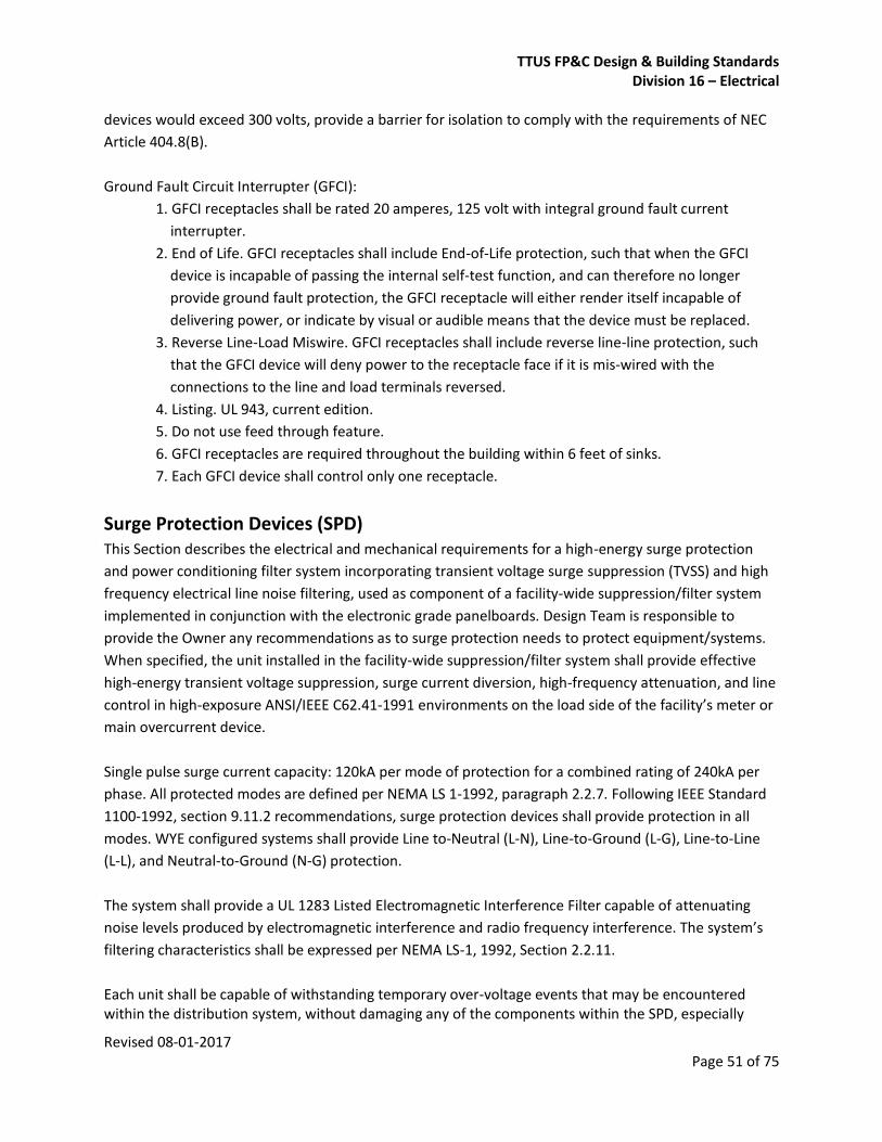
TTUS FP&C Design & Building Standards Division 16 – Electrical
Revised 08-01-2017 Page 51 of 75
devices would exceed 300 volts, provide a barrier for isolation to comply with the requirements of NEC
Article 404.8(B).
Ground Fault Circuit Interrupter (GFCI):
1. GFCI receptacles shall be rated 20 amperes, 125 volt with integral ground fault current
interrupter.
2. End of Life. GFCI receptacles shall include End-of-Life protection, such that when the GFCI
device is incapable of passing the internal self-test function, and can therefore no longer
provide ground fault protection, the GFCI receptacle will either render itself incapable of
delivering power, or indicate by visual or audible means that the device must be replaced.
3. Reverse Line-Load Miswire. GFCI receptacles shall include reverse line-line protection, such
that the GFCI device will deny power to the receptacle face if it is mis-wired with the
connections to the line and load terminals reversed.
4. Listing. UL 943, current edition.
5. Do not use feed through feature.
6. GFCI receptacles are required throughout the building within 6 feet of sinks.
7. Each GFCI device shall control only one receptacle.
Surge Protection Devices (SPD) This Section describes the electrical and mechanical requirements for a high-energy surge protection
and power conditioning filter system incorporating transient voltage surge suppression (TVSS) and high
frequency electrical line noise filtering, used as component of a facility-wide suppression/filter system
implemented in conjunction with the electronic grade panelboards. Design Team is responsible to
provide the Owner any recommendations as to surge protection needs to protect equipment/systems.
When specified, the unit installed in the facility-wide suppression/filter system shall provide effective
high-energy transient voltage suppression, surge current diversion, high-frequency attenuation, and line
control in high-exposure ANSI/IEEE C62.41-1991 environments on the load side of the facility’s meter or
main overcurrent device.
Single pulse surge current capacity: 120kA per mode of protection for a combined rating of 240kA per
phase. All protected modes are defined per NEMA LS 1-1992, paragraph 2.2.7. Following IEEE Standard
1100-1992, section 9.11.2 recommendations, surge protection devices shall provide protection in all
modes. WYE configured systems shall provide Line to-Neutral (L-N), Line-to-Ground (L-G), Line-to-Line
(L-L), and Neutral-to-Ground (N-G) protection.
The system shall provide a UL 1283 Listed Electromagnetic Interference Filter capable of attenuating
noise levels produced by electromagnetic interference and radio frequency interference. The system’s
filtering characteristics shall be expressed per NEMA LS-1, 1992, Section 2.2.11.
Each unit shall be capable of withstanding temporary over-voltage events that may be encountered within the distribution system, without damaging any of the components within the SPD, especially

TTUS FP&C Design & Building Standards Division 16 – Electrical
Revised 08-01-2017 Page 52 of 75
MOVs and other non-MOV parallel-connected elements, in accordance with NEMA LS-1 Section 2 2.2.6 and 3.6. Each unit shall provide temporary over-voltage protection for 3600 cycles at 160% of rated voltage. Monitoring shall include one set of status monitoring lights that will provide visual indication of voltage present to the SPD for each phase of protection. The lights shall also indicate when suppressor protection has degraded to any value of less than 50%. Status indicator lights that simply indicate the presence of voltage, and provide no indication of performance, will be unacceptable. Additionally, each unit shall include an audible alarm with battery backup, a current-sensing surge counter, and two sets of Form C contacts for remote alarm monitoring.
All units shall be UL 1449, Second Edition (2007), listed and labeled as a Surge Protection Device and
shall be listed and labeled to UL 1283 as an Electromagnetic Filter.
General. Install surge protection device (SPD) as close as practical to the electrical distribution wiring
system, in accordance with manufacturer’s wiring diagrams and written instructions and the applicable
requirements of the NEC, NEMA, ANSI, local codes, and Owner requirements.
Upon completion of installation, provide the start-up and testing services of a factory authorized
and factory-trained local service representative. Field testing shall use procedures, forms, instruments
and materials as submitted and accepted. The tests shall include:
1. Off-Line testing: Impulse injection to verify the system tolerances as well as verification of
proper neutral-to-ground bond at the facility service entrance and at each separately-derived
source. To be compared to factory benchmark test parameters supplied with each individual
unit.
2. On-Line testing: verification that suppression and filtering paths are operating with 100%
protection as well as verification of proper neutral-to-ground bond by measuring neutral-to-
ground current and voltage and by visual inspection at the facility service entrance and at
each separately-derived source.
3. Voltage measurements from Line-to-Ground (L-G), Line-to-Neutral (L-N), Line-to-Line (L-L),
and Neutral-to-Ground (N-G), taken at the time of the testing procedure.
Submit to the Owner’s Representative and to the Architect/Engineer copies of the startup test results
and the factory benchmark testing results for confirmation of proper suppression filter system function.
The SPD system shall be warranted against defective materials and workmanship for a period of ten
years.
Enclosed Safety Switches Submit arc-flash calculations and associated incident energy levels on each type of switch.
Specify switches that are UL-98 listed.

TTUS FP&C Design & Building Standards Division 16 – Electrical
Revised 08-01-2017 Page 53 of 75
Provide NEMA 1 switch enclosures for indoor dry locations and NEMA 4X, stainless steel for outdoor
locations unless otherwise shown.
Provide an operating handle suitable for padlocking in the OFF position with as many as three padlocks
of 5/16 inch diameter shank. Use a defeatable, front accessible, coin-proof door interlock to prevent
opening the door when the switch is in the ON position and to prevent turning the switch ON when the
door is open.
Provide incoming line terminals with an insulated shield so that no live parts are exposed when the door
is open.
Provide each switch with an isolated, fully rated neutral block. Make provisions for bonding the block to
the enclosure.
Provide each switch with a ground lug.
Where fusible switches are shown, provide switches with rejection-type fuse holders which are suitable
for use with fuses 600 Volt and below. Provide permanent marking inside switch enclosure for fuse type
and size.
Provide metal nameplates, front cover mounted, which indicate the switch type, catalog number and
horsepower rating (with both standard and time delay fuses).
Where used to serve motors, safety switches shall bear the horsepower rating equal to or exceeding
that of the motor which they serve regardless of the size or type specified on the drawings.
Where enclosed safety switches/disconnects are shown serving exterior and/or roof mounted
mechanical equipment, they shall be mounted separately from the equipment on unistrut where
mounting to the equipment will obstruct airflow or maintenance and/or where required by the Owner.
All racks/supports installed outside of the building shall be constructed of galvanized steel with cold
galvanizing applied to any field cuts, welds, etc. unless noted otherwise.
Where safety switches/disconnects are shown serving interior air handling equipment they shall be
mounted on the nearest wall or supported from structure above.
Install all safety switches/disconnects within sight of the motor they serve.
Install safety or disconnect switches where indicated, in accordance with the manufacturer’s written
instructions, and the applicable requirements of NEC. Install safety and disconnect switches in
accordance with the directions of the Owner’s Representative.

TTUS FP&C Design & Building Standards Division 16 – Electrical
Revised 08-01-2017 Page 54 of 75
Include manufacturer’s label indicating incident energy levels associated with calculated arc-flash
event(s) for motor starter fault conditions.
Interior Lighting This section includes interior luminaires with lamps, ballasts and accessories. Design all lighting using IESNA (Illuminating Engineering Society of North America). Illumination levels will be determined in design meeting with the Project Team based on task and other criteria. Apply the information from the current edition of IESNA Recommended Practice, Design Guide and Handbook publications.
Interior lighting shall be LED unless noted otherwise.
Typical LED luminaire (all models) shall be at minimum: 1. Life hours: 60,000 hours (L90/60,000) 2. CRI: 82
3. Lighting Loss Factor: 91%
4. Dimmable: 0-10V up to 1% or as stated otherwise. Typical lighting distribution: Volumetric, direct downlighting, direct/indirect (80/20), accent wall wash. Parabolic lighting shall be discussed with engineer/architect.
Typical accepted manufacturers: Acuity Brands, Copper Lighting, Hubbell, Phillips, and other specialty
lighting meeting design intention by architect/engineer.
Lighting Control Systems This section includes typical components of a building Lighting Control System. It is assumed all luminaires are of LED technology with 0-10V diming capabilities.
1. Motion Sensors: a. Coverage: 2000 ft² field of view 360˚ b. Technology: Ultrasonic combined with Passive Infrared. c. Sensor: intelligent self-adaptive with non-volatile memory. d. All power supplies shall be provided above the ceiling. e. Installation: ceiling mounted.
2. Lighting Management Panel:
a. NEMA-1, one single cabinet with 6-9 modules b. Provides relays, dimming, and switching capabilities. c. Panel shall be capable to support all types of loads including but not limited to: LED, LED
dimmed, electronic low voltage transformers, incandescent, halogen, fluorescent 0-10V dimmed, HID 0-10V dimmed.
d. Solid state lighting controls. e. 0-10v dimming capabilities
TTUS FP&C Design & Building Standards Division 16 – Electrical
Revised 08-01-2017 Page 55 of 75
f. Emergency connections. g. Universal voltage of operation (120 to 277VAC) 50/60 Hz. h. Feed through, or 4wire main lug (3 phase and neutral). i. Branch circuits 20-16 amps continuous rating, 14 kAIC j. Surge protected for 6KV, 3KA. k. Current ratings: @120V= 150A ; @277V= 65A. l. Environment: 32-104˚F (0 to 40˚C) m. Relative humidity less than 90% non condensing n. Controller with numeric display, with integral USB port for programming, standard Ethernet
port for communications. o. Typical Lighting Management Panel shall meet the following standards:
1. UL Listed 2. ANSI C82-11 Annex A (0-10V control) 3. ANSI E1.11, E1.20, E1.27 (DMX and RDM) 4. NEMA SSL7A (LED phase dimming control)
3. Lighting Control Master Panel a. Type: Capacitive LCD backlit touchscreen, thin profile. Glass with aluminum frame. b. On screen lighting design and setup. c. Alphanumeric scene and zone naming. d. Lighting Control: Forward and reverse phase dimming, 0-10V e. A minimum of 30 channels and scenes to control lighting. f. Integral astronomic timeclock. g. Onscreen scheduling, h. Automatic On with proximity sensor. i. Ethernet connection for remote configuration and control. j. Digital motion sensor, daylight harvesting, rs-232, contact closure and wall station input. k. On-board non-volatile memory. l. Typical Lighting Control Master Panel shall meet the following standards:
1. UL Listed 2. FCC part 15 3. ANSI E1.11, E1.20 4. IEEE 802.15 Bluethooth 5. IEEE 802.3 Ethernet 6. RoHS compliant.
4. Digital Wall Stations a. Architectural push button wall station b. Multi-lighitng scenes capabilities to manage lighting levels. c. Shall be capable to communicate with other devices of same Lighting Control Family. d. Shall be capable for 2-8 independently programmable buttons per station. e. Backlit buttons f. Status LED indicators. g. Wall plate and face plate shall be in at least 3 colors and easy to customize. h. Supply voltage: 16VDC – 28 VDC. i. Environment: 32-104˚F (0 to 40˚C) j. Relative humidity less than 90% non condensing
TTUS FP&C Design & Building Standards Division 16 – Electrical
Revised 08-01-2017 Page 56 of 75
k. Communications: through EIA-485 connector and two conductors for power.
Contractor shall provide all related power packs for controls. Additional control devices necessary to achieve daylight harvesting and other types of Lighting Control as indicated on ASHRAE-2012 and/or IECC 2015, shall be provided by engineer of record. Typical accepted manufacturers include: Acuity Brands (Fresco and nLight), Hubbell, and Lutron. Other manufacturers shall be under the approval of Owner and the Design Team. All devices shall be of same manufacturer.
Emergency Egress Lighting The Emergency Egress Luminiare shall be of the following characteristics:
1. The luminaire shall blend with architectural design, in both color and style.
2. Full cut-off optics to achieve unobtrusive illumination of space and path.
3. Housing: Aluminum, marine grade, chemically primed, with polyester powder coat. Housing
shall be secured with stainless steel TORX head screws
4. Lens: UC stabilized extruded polycarbonate.
5. LED driver at 3500K and >82 CRI.
6. Projected life: L70 at 75,000 hours at 50˚C
7. Warranty: 10 years.
8. Listings: UL, Wet listed.
9. Operating voltages: 120-277 VAC.
10. Provide battery pack 1025-1250 lm self contained with 90 minutes at 0-55˚C
11. The luminaire shall be vandal resistance.
Contractor shall provide luminaires in Dark Bronze finish or as indicated by Engineer/Architect.
Exterior Lighting This section includes exterior luminaires with lamps and ballasts, luminaire-mounted photoelectric relays, exterior wireless controls, and poles and accessories. Design all lighting using IESNA (Illuminating Engineering Society of North America). Apply the information from IESNA Recommended Practice, Design Guide and Handbook publications. Illumination levels will be determined in design meeting with the Project Team based on task and other criteria. Apply the lighting distributions set out in the Dark Sky International guidelines to minimize sky glow. Exterior lighting to be LED unless noted otherwise. Design should have limited wall packs.

TTUS FP&C Design & Building Standards Division 16 – Electrical
Revised 08-01-2017 Page 57 of 75
Verify normal operation of lighting units after installing luminaires and energizing circuits with normal
power source.
Measure light intensities at night. Use photometers with calibration referenced to NIST standards.
Comply with the IESNA testing guide(s) for the applicable lighted task.
Prepare a written report of tests, inspections, observations, and verifications indicating and interpreting
results. If adjustments are made to lighting system, retest to demonstrate compliance with standards.
Special warranty to be manufacturer's standard form in which manufacturer agrees to repair or replace
products that fail in materials or workmanship; that corrode; or that fade, stain, perforate, erode, or
chalk due to effects of weather or solar radiation within specified warranty period. Manufacturer may
exclude lightning damage, hail damage, vandalism, abuse, or unauthorized repairs or alterations from
special warranty coverage.
1. Warranty Period for Luminaires: Five years from date of Substantial Completion.
2. Warranty Period for Metal Corrosion: Five years from date of Substantial Completion.
3. Warranty Period for Color Retention: Five years from date of Substantial Completion.
4. Warranty Period for Lamps: Replace lamps and fuses that fail within 24 months from date of
Substantial Completion.
5. Warranty Period for Poles: Repair or replace lighting poles and standards that fail in finish,
materials, and workmanship within manufacturer's standard warranty period, but not less
than five years from date of Substantial Completion.
Furnish extra materials described below that match products installed and that are packaged with
protective covering for storage and identified with labels describing contents.
1. Lamps: 10 for every 100 of each type and rating installed. Furnish at least one of each type.
2. Glass and Plastic Lenses, Covers, and Other Optical Parts: 10 for every 100 of each type and
rating installed. Furnish at least one of each type.
3. Ballasts: 10 for every 100 of each type and rating installed. Furnish at least one of each type.
4. Globes and Guards: 10 for every 50 of each type and rating installed. Furnish at least one of
each type.
General requirements for poles and support components
1. Structural Characteristics: Comply with AASHTO LTS-4.
2. Wind-Load Strength of Poles: Adequate at indicated heights above grade without failure,
permanent deflection, or whipping in steady winds of 100 MPH, with a gust factor of 1.3.
3. Mountings, Fasteners, and Appurtenances: Corrosion-resistant items compatible with
support components.
4. Concrete Pole Foundations: Cast in place, with anchor bolts to match pole-base flange.
Concrete. Reinforcement, and formwork are specified in Section 3.
a. Bases installed in parking lots in curbed planters that prevent vehicle contact shall be

TTUS FP&C Design & Building Standards Division 16 – Electrical
Revised 08-01-2017 Page 58 of 75
set at 4” above the curb height.
b. Bases installed in parking lots that are subject to vehicle contact shall be set 36”
above the pavement.
c. Bases installed adjacent to sidewalks shall be set flush against the walk and 4” above
the edge of the walk.
Steel Poles
1. Poles: Round, tapered. Comply with ASTM A 500, Grade B, carbon steel with a minimum
yield of 46,000 psig 1-piece construction up to 35 feet in height with access handhole in pole
wall. Poles shall be four-bolt mounted to a concrete foundation.
2. Steel Mast Arms: Single-arm type, continuously welded to pole attachment plate. Material
and finish same as pole.
3. Brackets for Luminaires: Detachable, cantilever, without underbrace; match pole finish and
material.
4. Pole-Top Tenons: Fabricated to support luminaire or luminaires and brackets indicated, and
securely fastened to pole top.
5. Grounding and Bonding Lugs: Welded 1/2-inch threaded lug, complying with requirements in
Standard for "Grounding and Bonding," listed for attaching grounding and bonding
conductors of type and size listed in that Standard, and Accessible through handhole.
6. Powder-Painted Finish: Comply with NAAMM's "Metal Finishes Manual for Architectural and
Metal Products" for recommendations for applying and designating finishes.
a. Surface Preparation: Clean surfaces to comply with SSPC-SP 1, "Solvent Cleaning," to
remove dirt, oil, grease, and other contaminants that could impair paint bond. Grind
welds and polish surfaces to a smooth, even finish. Remove mill scale and rust, if
present, from uncoated steel, complying with SSPC-SP 5/NACE No. 1, "White Metal
Blast Cleaning," or SSPC-SP 8, "Pickling."
b. Interior Surfaces of Pole: One coat of bituminous paint, or otherwise treat for equal
corrosion protection.
c. Exterior Surfaces: Manufacturer's standard finish consisting of one or more coats of
primer and two finish coats of Sherwin Williams “Dark Bronze”
Other Manufacturers with a dark bronze finish as standard shall submit a color
sample of 4” square on similar materials as the construction of the pole for TTU to
determine an acceptable match to the standard.
Aluminum poles to be 14' aluminum round tapered with pedestal base bolted to concrete foundation
manufactured by:
1. Lexington Standard Corporation
2. Hapco Lighting Company
3. Valmont poles.
TTUS FP&C Design & Building Standards Division 16 – Electrical
Revised 08-01-2017 Page 59 of 75
Cast concrete poles to be embedded in tamped earth (typ.) or embedded in concrete manufactured by:
1. Wasau Tile Terraform Div. of Wausau, WI
2. Custom Design Precast of Weston, WI
3. Stone Legends
Luminaries and Equipment 1. Pole-top for 14' Lexington round tapered aluminum pole: a. Lumec # Z14-002-65W42LED4K-R-AC-RLE5-277-SFZ3-VPA-BRTX-LMS13270B with Double-T. b. Lumec Z14-002-65W42LED4K-R-AC-RLE5-277-SFZ3-VPA-BRTX -LMS13270D without Double-T. c. King Luminiaire K428-OAAR-V-75(SSL)-5000-277-K31-TTS-XPG add Double-T when required. Note: The Double-T shall only be used on TTU Athletic Facilities. 2. Pole-top for TTU concrete Light Pole: a. Lumec # Z47A-002-65W42LED4K-R-AC-RLE5-277-SFZ4-TN3-VPA-BRTX-LMS13218B with Double-T. b. Lumec # Z47A-002-65W42LED4K-R-AC-RLE5-277-SFZ4-TN3-VPA-BRTX -LMS13218D without Double-T. 3. Parking lot fixtures: a. McGraw-Edison: GLEON-AE-06-LED-T4FT-BZ-PER7 on 35’ round tapered steel pole on 2’ concrete pole base. b. Provide wireless lighting controls. All wireless lighting controllers shall provide the following features and capabilities:
1. 0-10VDC (sinking) dimming control in 0.1V increments based on LED driver high and low operating range; 0V turns fixture power OFF.
2. Direct motion detector interface/motion detector input 3. Scheduled control 4. Over the air flashing (program updates)
Wireless Outdoor Lighting Controller (externally top mounted)
1. Nodes shall be a one piece, self-contained IP66-rated device, externally mounted, capable of providing 0-10VDC dimming, bi-level and on and off control to luminaire with the following features:
2. All wiring routed through ½” threaded nipple for universal mounting or through 3 blade twist lock with low voltage pass-through for control wiring.
a. Twist lock model shall interface with ANSI 136.41 receptacles. 3. Capable of replacing existing photocell and receptacle for retrofit applications
4. Operation and control 100-480 VAC, 1000 watt
a. Peak power use by nodes shall be less than two (2) watts.
b. Node shall provide 12V power for optional microwave or passive infrared (PIR) occupancy sensor
5. Motion detector and call button inputs 6. Up to 9 time based scheduled actions per day
a. Stepped switching and 0-10VDC dimming in 0.1V increments 7. Adjustable photocell thresholds 8. Data logging

TTUS FP&C Design & Building Standards Division 16 – Electrical
Revised 08-01-2017 Page 60 of 75
9. Revenue grade revenue grade smart metering chipset that measures and logs energy consumption at accuracy levels better than +-1% nominally.
10. Failure and performance reporting 11. Demand responsive to real time inputs from customer systems and utilities 12. DOT (Direction of Travel) capable for use with motion detectors for illuminating pathways ahead of
foot/biking traffic 13. Peer to peer communication to provide group activation by single motion detector inputs 14. 900 MHz radio with 1 mile range between devices, 2 miles between Gateways and devices. 15. Over the air flashing for program updates. 16. No additional components for control are to be installed inside the fixture housing.
Lumewave TOP900 Series: TOP900TLX with NEMA ANSI 136.41 7-pin connector; TOP900TN with threaded nipple connection.
Lumewave system is already deployed in Texas Tech Campus, and all parts and components shall be compatible with existing. Other manufacturers will be consider by Engineer.
Bollards LED, 32” height, 6” rounds, dark bronze finish, with louvers on top. The body shall be extruded aluminum with a heavy cast aluminum base. The internal globe is fluted, clear tempered glass, fully gasketed. The LED source shall be 20LED (IES type V), 4200K, and universal voltages. Contractor shall provide the following additional items if requested by engineer: 0-10V dimming interface, battery pack 90 minutes, weather proof GFCI duplex receptacle rated 20A, 125V, USB port for charging with cover access.
1. Ground-mounted accent or building lighting: LED, wattage & fixture as specified per specific project or approved equal. Architectural Wall Sconce: LED technology (capable to replace 175W PMH) with one or two LED engines. 4000K, type IV distribution. Multivolt 120-277VAC. Finish to be Dark Bronze. Contractor shall provide the additional items if requested by engineer: 0-10V dimming interface, integral battery pack (if luminaire is to perform as egress path). Specify Lithonia Lighting half round WST, WSR, or WSQ or approved equal. Photoelectric Control: Connect to the electrical system on the nearest facility and control all area lighting with a single photocell mounted on the building with the sensor oriented to a clear view of the North sky. . Pole Installation 1. Align pole foundations and poles for optimum directional alignment of luminaires and their mounting provisions on the pole. 2. Concrete Foundations: Set anchor bolts according to anchor-bolt templates furnished by pole manufacturer. Concrete materials, installation, and finishing requirements are specified in Standard for "Cast-in-Place Concrete." 3. Foundation-Mounted Poles: Mount pole with leveling nuts, and tighten top nuts to torque level recommended by pole manufacturer. 4. Embedded Poles with Tamped Earth Backfill: Set poles to depth below finished grade as
indicated on Drawings or per manufacturer’s recommendations.
5. Embedded Poles with Concrete Backfill: Set poles in augered holes to depth below finished
TTUS FP&C Design & Building Standards Division 16 – Electrical
Revised 08-01-2017 Page 61 of 75
grade indicated on Drawings or per manufacturer’s recommendations.
a. Make holes 6 inches in diameter larger than pole diameter.
b. Fill augered hole around pole with air-entrained concrete having a minimum
compressive strength of 3000 psi at 28 days, and finish in a dome above finished
grade.
c. Cure concrete a minimum of 72 hours before performing work on pole.
Ground metal poles and support structures according to Division 16 Section "Grounding and Bonding."
1. Install grounding electrode for each pole, unless otherwise indicated.
2. Install grounding conductor pigtail in the base for connecting luminaire to grounding system.
Ground nonmetallic poles and support structures according to Standard 16 Section “Grounding and
Bonding."
1. Install grounding electrode for each pole.
2. Install grounding conductor and conductor protector.
3. Ground metallic components of pole accessories and foundations.
Lighting Design Parameters Luminaires indicated on plans and schedules are selected to accomplish the following average
maintained illumination levels, as follows:
1. Offices, Workrooms, and Conference Rooms.
a. Average = 50 – 75 foot-candles.
b. Uniformity ratio (Max/Min) not to exceed 4:1.
c. Configure luminaires for bi-level or multi-level lighting, as indicated on Luminaire
Schedule and plans.
d. Working height = 30 inches above finished floor.
2. Multi-Purpose Rooms:
a. Average = 50 – 75 foot-candles.
b. Uniformity ratio (Max/Min) not to exceed 5:1.
c. Working height = 30 inches above finished floor.
3. Exercise Areas and Weight Areas:
a. 75 foot-candles, maximum. 30 foot-candles, minimum.
b. Uniformity ratio (Max/Min) not to exceed 5:1.
c. Working height = finished floor (zero inches).
4. Restrooms:
a. Average = 20 – 30 foot-candles.
b. Uniformity ratio (Max/Min) not to exceed 6:1.
c. Working height = finished floor (zero inches).
5. Corridors and Stairs:
a. Minimum = 10 foot-candles.
b. Uniformity ratio (Max/Min) not to exceed 10:1.
TTUS FP&C Design & Building Standards Division 16 – Electrical
Revised 08-01-2017 Page 62 of 75
6. Emergency egress lighting along corridors, stairs, and other egress paths as designated by the
Architect:
a. Minimum = 1 foot-candle.
b. Uniformity ratio (Max/Min) not to exceed 10:1.
c. Working height = finished floor (zero inches).
8. Mechanical Rooms, Electrical Rooms, and Elevator Equipment Rooms:
a. Minimum = 20 foot-candles.
b. Uniformity ratio (Max/Min) not to exceed 6:1.
c. Working height = finished floor (zero inches).
d. Data/Telecommunications /IT= 30 foot-candles.
e. Uniformity ratio (Max/Min) not to exceed 5:1.
f. Working height = 30 inches above finished floor.
9. Storage Rooms. Average = 15 foot-candles. Working height = 30 inches above finished floor.
10. Exterior Walkway Lighting:
a. Average = 3-5 foot-candles.
b. Minimum = 1 foot-candles.
c. Uniformity ratio (Max/Min) not to exceed 10:1.
d. Working height = finished grade (zero inches).
11. Building Perimeter:
a. Minimum = 1 foot-candle, along perimeter of building exterior.
b. Uniformity ratio (Max/Min) not to exceed 10:1.
c. Working height = finished grade (zero inches).
Luminaires, as submitted and as installed, shall achieve the above illumination levels, subject to Owner’s
final acceptance of project.
Lighting level design shall be per IESNA (Illuminating Engineering Society of North America)
recommendation.
The power consumption for interior and exterior lighting shall not exceed power allowance as per
ASHRAE 90.1 latest revision.
Where indicated on drawings, provide emergency lighting units self-contained complete with batteries,
charger, and lamps to provide automatic emergency lighting upon failure of normal power. Battery shall
be 12 volts, maintenance free, lead calcium type, with 1.5 hours minimum capacity to supply the
connected lamp load. Where larger capacity is indicated on plans or schedules, provide unit with larger
capacity. Charger shall be solid state capable of maintaining the battery fully charged during normal
conditions, and capable of recharging discharged battery to full charged within 12 hours. Emergency
lighting units shall be compliant with UL924, NFPA 101 (Life Safety Code), NFPA 70 (National Electrical
Code – NEC). Typical locations for battery pack include Research laboratories, theaters, and others per
engineer recommendations.
TTUS FP&C Design & Building Standards Division 16 – Electrical
Revised 08-01-2017 Page 63 of 75
Provide LED-type vandal-resistant exit signs as scheduled. Incandescent and fluorescent exit signs are
not acceptable. Exit signs shall have stencil face with 6-inch high letters. Provide red letters with smooth
diffusion face, unless otherwise indicated or scheduled. Individual LED’s shall not be visible through the
diffusion material. Provide directional arrows as indicated. Provide exit signs with battery backup.
Battery shall be a maintenance free lead-calcium or nickel-cadmium, 4 to 6 volt, with 1.5 hour minimum
capacity to supply connected lamp load. Where larger capacity is indicated on plans or schedules,
provide unit with larger capacity. Exit signs shall be compliant with UL924, NFPA 101 (Life Safety Code),
and Energy Star.
Provide enclosed, mechanically-held, latching, magnetic lighting contactor designed to withstand the
large initial inrush current of tungsten and ballast lamp loads as well as non-motor (resistive) loads
without contact welding.
Install luminaires in accordance with the manufacturer’s written instructions, Owner’s requirements, the
applicable requirements of NEC and local and national Codes, Standards, and regulations.
Data/Communications Design Professionals shall reference Texas Tech OP 61.12 “Installation of Cabling in Buildings and
Tunnels” for more information.
Design Professionals shall reference Texas Tech OP Section 52 “Information Technology” for more
information.
Reference the TTU Telecommunications Services
http://www.net.ttu.edu/standards/cablingdesigninfo.aspx for Communications Cabling Specifications.
Lightning Protection System The Engineer of Record shall perform simplified risk calculations and will provide the owner with their
recommendations on whether a lightning protection system is recommended. If required, the Lightning
protection systems shall be designed by a Certified Lightning Designer/Installer. All connections to the
grounding system shall be directed by the plans and specifications of the lightning design.
The system design shall equal or exceed the requirements of UL 96A for a Master “C” Label and FM
Global Data Sheet 5-11. Upon completion, the lightning protection system shall be inspected and
certified by a third party representative hired by the contractor and approved by the Owner. The
lightning protection system shall pass inspection. If the system does not pass inspection, the lightning
protection contractor must make corrections to the system to pass inspection. The master label shall be
installed in the main electrical room near the door wall.

TTUS FP&C Design & Building Standards Division 16 – Electrical
Revised 08-01-2017 Page 64 of 75
The subcontractor shall be one that is recognized as being regularly engaged in the design and
installation of lightning protection systems. The subcontractor must be listed by Underwriters’
Laboratories, Inc., and must employ competent personnel fully qualified in the field of lightning
protection.
The system furnished under this specification shall be the standard product of a manufacturer regularly
engaged in the production of lightning protection systems and shall be the manufacturer’s latest
approved design. Listing of the manufacturer in the lightning protection section of the current edition of
Underwriters’ Laboratories, Inc., Electrical Construction Materials List will be accepted as compliance
with this requirement. Materials used in connection with the installation of the lightning protection
system shall be approved for lightning protection systems by the Underwriters’ Laboratories, Inc. No
combination of materials shall be used that forms an electrolytic couple of such nature that corrosion is
accelerated in the presence of moisture. Where unusual conditions exist which would cause
deterioration or corrosion of conductors, conductors with suitable protective coatings or oversize
conductors shall be used. If a mechanical hazard is involved, the conductor size shall be increased to
compensate therefore, or suitable protection shall be provided. The conductors may be protected by
covering them with molding or tubing, preferably made of nonmagnetic material.
Except where approved by Owner to be specified as aluminum, all conductors shall be copper and of the
grade ordinarily required for commercial electrical work generally designated as being 98 percent
conductive when annealed. Conductor minimum sizes are listed in Tables 3-4 and 3-5 of NFPA 780. Main
conductor and secondary conductor cable sizes shall be the same. Where conductors are placed in
contact with aluminum building materials such as parapet wall cap or siding, provide aluminum
conductors. Transition to copper conductors where no longer in contact with aluminum building
materials.
Air terminals shall be nickel-plated solid copper with tapered bullet point tips (in lieu of sharp point tips).
Minimum air terminal size shall be 5/8-inch diameter by 24 inches long. Where air terminals longer than
24 inches are required, solid copper rods of the appropriate length with threaded ends may be securely
attached to the air terminals for extensions. Provide a three-leg tripod brace for each air terminal at an
open roof location. Secure the triangular brace to the roof in a manner approved by the roof vendor. All
other air terminals shall have a bipod brace. Conductor connections to air terminals shall be bolted.
Lightning air terminals that employ early-streamer devices, radio-active rods or eliminators shall not be
acceptable.
Ground rods shall be copper-clad steel, 3/4-inch diameter by 10 feet in length, or longer if required.
Specify a complete lightning protection system consisting of air terminals, conductors, connectors,
attachments, grounding and necessary appurtenances to comply with minimum requirements listed in
the referenced standards. The system shall be installed in a neat workmanlike manner and without
interfering with other building systems.
TTUS FP&C Design & Building Standards Division 16 – Electrical
Revised 08-01-2017 Page 65 of 75
All antennas shall be grounded.
Fire Alarm and Smoke Detection System The system shall have a microprocessor based intelligent addressable fire alarm system with printer and
voice evacuation. The fire alarm system and design shall be Fire Control Instruments E-3 Series or
approved equal. The TTU Fire Marshall is the Authority Having Jurisdiction for the fire alarm system.
1. The system shall have the capabilities of sounding a digitally pre-recorded voice/audible fire
evacuation message in English and Spanish and also a digital severe weather message that
can be activated through a separate pull station or button labeled for severe weather. No
strobes are required for weather alerts.
2. The system shall have the capabilities of flashing the strobes after the system has been
silenced and until system reset has occurred.
3. The fire alarm system shall have the capabilities of shutting down all heating and air handling
units during general alarm.
4. The fire alarm system shall monitor all ancillary life safety systems.
5. All corridors, stairwell and any other fire door that would tend to be propped open will be
equipped with magnetic door hold open devices that will release on the activation of the fire
alarm system or loss of power.
6. All fire alarm systems shall be tied into and monitored at Central Heating and Cooling Plant 1
(CHACP 1) emergency maintenance facility and Texas Tech Police Department through the
U.L. Listed fiber loop system or Ethernet. The head-end monitoring equipment is Fire Control
Instruments and all new equipment must be compatible and capable of interfacing with the
current equipment. The fire alarm contractor is responsible for the purchase and installation
of all of the equipment that is required to make the interface.
7. Fire alarm testing will be done only after the elevator has been certified by a State QEI
Inspector.
8. Fire alarm duct detectors should be programmed for supervisory condition due to the dusty
conditions of this area.
9. IDC and SLC circuits shall be allowed to be class “B” circuits, NAC circuits shall be allowed to
be class “B” circuits unless a High Rise classification requires Class A circuit configuration.
10. Install plastic stopper covers for each manual pull station and weather alert button unless
directed otherwise by the Owner.
11. Exit signs shall not be interfaced to the fire alarm system to flash on alarm. Strobes shall be
located relevant to exit locations to draw attention to exit doors.
The system shall include, but not be limited to the following elements:
1. Master system CPU including all fire detection, voice/audio and visual evacuation alarm
control modules, and supervised power amplifiers with the required back up modules.
2. Circuit interface panels including all modules.
3. Power supplies, batteries and battery chargers.
TTUS FP&C Design & Building Standards Division 16 – Electrical
Revised 08-01-2017 Page 66 of 75
4. Pre-amplifiers, amplifiers, tone generators, and master microphone.
5. Equipment enclosures.
6. Intelligent addressable manual pull stations, heat detectors, analog smoke detectors, alarm
monitoring modules, and supervised control modules.
7. Beam smoke detection system.
8. Annunciator panel and printer.
9. Voice/Audible and visual evacuation signals.
10. Color graphic displays and historical archiving.
11. Software and firmware as required to provide a complete functioning system.
12. Wiring and raceway.
13. Installation, testing and certification and training.
14. Interface with air handling units and stairwell pressurization system.
15. Interface with Clean Agent Suppression System serving computer rooms.
16. Remote annunciator panel.
Before commencing work, submit data showing that the Contractor has successfully installed fire alarm
systems of the same type and design as specified, or that they have a firm contractual agreement with a
subcontractor having the required manufacturers’ training and experience. The Contractor shall include
the names and locations of at least two installations where the Contractor, or the subcontractor above,
has installed such systems. Specify the type and design for each system and furnish documentation that
the system has performed satisfactorily for the preceding 18 months.
Provide the services of a representative or technician from the manufacturer of the system, experienced
in the installation and operation of the type of system provided. The representative shall be licensed in
the State of Texas. The technician shall supervise installation, software documentation, adjustment,
preliminary testing, final testing and certification of the system. The technician shall provide the
required instruction to the Owner’s personnel in the system operation, maintenance and programming.
The system shall be a complete, electrically supervised multiplex style fire detection and voice
evacuation system with intelligent analog alarm initiation, to be device addressable and annunciated as
described and shown on the Drawings. Fire Control Instruments is the acceptable manufacture. Other
manufacturers meeting the requirements of this specification for design, function and performance will
be considered upon submittal of manufacturer’s data to the Texas Tech University Fire Marshal’s Office.
The system shall support intelligent analog smoke detection, manual station, water flow, supervisory,
security, and status monitoring devices. Fire alarm, supervisory, trouble, security and status shall each
be treated as a separate level of alarm, each with its own level of priority. The system shall also support
amplifiers, voice/visual circuits, and stairwell pressurization fans and dampers.
The system shall be programmed in the field via a laptop computer. All programmed information shall
be stored in nonvolatile memory after loading into the control panel. No special programming terminal
TTUS FP&C Design & Building Standards Division 16 – Electrical
Revised 08-01-2017 Page 67 of 75
or prom burning shall be required and the system shall continue in service during reprogramming.
Systems requiring on line terminal programming or not capable of mass reading of panel software for
offsite documentation or editing will not be considered acceptable. Disabling of devices must be able to
be accomplished by push buttons located on the front of the main control panel and must be capable of
doing this by device type, floor, zone etc. This disabling feature shall also include flow and tamper
switches, etc., that may require maintenance. In the event of an alarm or power disruption this action
of disabling shall remain intact after the reset function has been activated. The alarm panel shall alert
the technician that devices have been disabled and give the option to keep them disabled. This will
prevent the inadvertent clearing of these disabled devices and cause false alarms due to repairs or work
in progress.
Each intelligent addressable device on the system shall be displayed at the fire alarm control panel by a
unique alpha numeric label identifying its location.
Activation of any alarm verified smoke detector in a single elevator lobby or an elevator equipment
room shall, cause the recall of the elevators to the terminal floor and the lockout of controls. In the
event of recall initiation by a detector in the first floor lobby, the recall shall be to the alternate floor.
Activation of any heat detector in the elevator machine room, elevator pit, or elevator shaft shall shunt
trip the circuit breaker serving the associated elevators.
Unless otherwise allowed by the TTU Fire Marshall, all wiring shall be run in metal conduit throughout.
Paint all junction box covers red.
Perform work in accordance with the requirements of NEC, NFPA 70, NFPA 72, TTU Fire Marshall’s
Office, and Factory Mutual recommendations.
Coordinate with Telecommunications installer, with Division 15 subcontractors.
Complete and submit to the Owner a Certificate of Compliance in accordance with NFPA 72.
Fire pumps shall report a “general fire alarm” back to CHACP 1 upon operation.
A written acceptance test procedure (ATP) for testing the fire alarm system components and installation
will be prepared by the Acceptance Inspector in accordance with NFPA 72, and the Owner’s
requirements. The Contractor shall be responsible for the performance of the ATP, demonstrating the
function of the system and verifying the correct operation of all system components, circuits, and
programming.
The Contractor shall warrant the entire system against mechanical and electrical defects for a period of
18 months. This period shall begin upon completed certification and test of the system. During this
TTUS FP&C Design & Building Standards Division 16 – Electrical
Revised 08-01-2017 Page 68 of 75
warranty period the contractor shall respond to a trouble call within 2 hours for problem determination,
and resolution to the problem within 24 hours.
Construction documents for fire alarm systems shall be submitted for review and approval prior to
system installation. Construction documents shall include, but not be limited to, all of the following:
1. A floor plan which indicates the use of all rooms.
2. Locations of alarm-initiating and notification appliances.
3. Alarm control and trouble signaling equipment.
4. Annunciation.
5. Power connection.
6. Battery calculations.
7. Conductor type and sizes.
8. Voltage drop calculations.
9. Manufacturers, model numbers and listing information for equipment, devices and materials.
10. Details of ceiling height and construction.
11. The interface of fire safety control functions.
12. Systems and their components shall be listed and approved for the purpose for which they are
installed.
Access Control Reference Texas Tech OP&P 61.14 “Electronic or Keyless Locking Systems” for design reference (security
systems in housing facilities are not addressed in this OP). The TTU Operations Division is responsible
for the management of all locking systems to university facilities through the university's security
systems manager within the Texas Tech University Lock Shop (TTULS). Standards and programs have
been established for the control and issuance of keys, development of keying systems, standardization
of hardware, and maintenance programs for the upkeep of these systems. Installation of systems other
than those approved in the standards or deviation from the standards may occur only with the approval
of the Managing Director of BMC under the guidelines set forth in this OP.
Due to the large number of electronic or keyless security systems available on the open market,
standards and limitations must be established for the use of these systems on the TTU campus. The
selection of the two systems listed above provides departmental security and flexibility without
jeopardizing existing security, and allows the TTU Operations Division and the Texas Tech Police
Department to maintain the systems without heavy investment in inventories and equipment.
Two locking systems have been selected that will serve the requirements of most departments. Requests to install electronic or keyless locking systems will be limited to the selection of one of the systems described in OP 61.14. The elected systems allow any departmental requirement to be met. The TTULS and the Texas Tech Police Department will assist departments in making selections. The only locking systems allowed on campus will be either C-CURE for security or CS Gold for access. The two approved systems are limited to:
TTUS FP&C Design & Building Standards Division 16 – Electrical
Revised 08-01-2017 Page 69 of 75
a. C-CURE C-CURE is a scalable security management solution encompassing complete access control and advanced event monitoring. The system integrates with critical business applications including CCTV and video systems from American Dynamics (Intellex Digital Video Management Systems and VideoEdge NVR) and third party devices such as fire alarms, intercoms, and burglar and other alarms. This system is managed and maintained by the Texas Tech Police Department. The TTU official ID card can be used for access or specialized access devices are obtainable from vendors at the expense of each department on campus. The Texas Tech Police Department can assist in providing a list of vendors for purchasing these devices. The Texas Tech Police Department will maintain a list of authorized people who can request and approve access to employees or students. Access changes including removal, addition, or transfer will be completed through the KMS http://is.operations.ttu.edu/odkms/default.aspx. The Texas Tech Police Department is located at 413 Flint Avenue and will make changes to the system between the hours of 8 a.m. and 5 p.m. Monday through Friday. b. CS Gold CS Gold offers wireless or wired on-line locks, including biometric readers. CS Gold hardware within E&G facilities will be installed and maintained by the Electronic Maintenance Shop and the Lock Shop. Access changes including removal, addition, or transfer will be completed through the KMS (http://is.operations.ttu.edu/odkms/default.aspx). The CS Gold systems security features include Banner synchronization on a daily basis, lock down, and emergency modes. New employees, students, or existing staff can obtain new or replacement TTU ID cards from the TTU ID Office located at the Student Union Building, Room 103, between the hours of 8 a.m. and 5 p.m. Monday through Friday.
Any new electronic or keyless system will interface or coexist with the existing restricted keyway system.
The existing master key will remain functional for service, custodial, police, and emergency access. If an
electronic key/card system replaces the existing key/lock system, the university Lock Shop will control
the issuance of key/cards under the same provisions outlined in OP 61.15 “Control and Issue of Keys to
University Buildings”.
All access control providers interested in bidding must have a valid license through the Texas
Department of Public Safety and Private Security Bureau for their portion of the work. The awarded
Contractor will be required to submit this information to the Texas Tech Police Department. The Texas
Tech Police Department may validate the licensing submitted with the State at their option.
Base the specifications on the Software House C:Cure 9000 Security Management System. The existing
security management system (C:Cure System) is located at Texas Tech Police Department. Contractor
will be required to provide IP connection and programming of new software house security devices,
camera system and controller to be accessed on Texas Tech Police Department existing C:Cure Security
System. The Company of Record for the Texas Tech University C:Cure System is Firetrol. Firetrol will be
the only company authorized to add or modify the existing system.

TTUS FP&C Design & Building Standards Division 16 – Electrical
Revised 08-01-2017 Page 70 of 75
NOTE: TTU University Student Housing is currently using CBORD as their card access system and Bosch
DVR’s or ExacqVision for their video surveillance. The CBORD card access system is/has been used in
existing academic/administration buildings where “security” is not needed but card access is needed.
The Design Professional needs to clarify with the Owner and TTU Police Department on the type of
system to specify.
The access control system will be a separate system from the video surveillance camera system. The
access control system will operate from existing C:Cure software system at Texas Tech Police
Department.
The access control system shall be from a single-source manufacturer that specializes in intrusion
detection and access control systems with a minimum of 5 years’ experience. Installer shall be a
company specializing in intrusion detection and access control systems with a minimum of three years’
experience on systems of similar size and scope. Technicians working on project must have been
certified on the hardware and software used for this project.
A final inspection walk-through will be conducted with the Texas Tech Police Department to verify
system operation and final acceptance of the work.
All equipment, materials, and labor shall have a two year warranty from the date of final acceptance by
the Owner.
1. Provide any software maintenance updates or upgrades at no additional cost to the Owner for this period.
2. Perform two (2) scheduled preventative maintenance site visits per year during the warranty period.
3. Normal business hours shall be 8 AM to 5 PM Monday through Friday. Calls for service before noon shall be responded to on-site before the end of the day. Calls after noon shall be responded to on-site by noon the following business day.
4. The installer shall have duplicate system parts available within 50 miles of installation site should any part of the system fail.
Basic Central System Components
1. If a new installation at a regional campus is needed, a computer server running the CCure 9000
system will also be required. This server will control all of the buildings at the regional campus.
2. Security Controllers: Software House Istar Pro, Edge or Ultra. IP-enabled Control Panel. Unless
otherwise noted, the Istar Pro should be a 16 door controller.
3. Input Modules: Software House I8-CSI. Enclosure: RM-DCM-CAN.
4. Output Modules: Software House R8 Output Module. Enclosure: RM-DCM-CAN.
5. Card Readers:
a. HID
b. SoftwareHouse
6. Door Strikes or electronic lock: TBD based on door configuration and TTPD recommendations.
7. Request-to-Exit: Bosch DS150i Series or approved equal.

TTUS FP&C Design & Building Standards Division 16 – Electrical
Revised 08-01-2017 Page 71 of 75
8. Door Contacts: Sentrol or approved equal.
9. Overhead Door Contacts: Sentrol or approved equal.
10. Access Power Controllers: Supply: Altronix Maxim 33 or approved equal.
11. Panic Button: USP HUB2 Series or approved equal.
12. Proximity Cards: HID Corporate 1000. Contractor shall verify requirements with Texas Tech
Police Department.
13. Motion Sensor: Sentrol or approved equal.
14. No substitutions. All Devices shall be compatible with existing system.
15. All security access and camera systems shall derive power from new emergency panels (fed
from generator). 12 volt battery backup to provide 12 hours of standby power supply shall
be provided.
Hardware Requirements
1. Controllers:
a. Provide one (1) Software House Istar Pro which supports sixteen (16) readers. (if
required)
b. Provide one (1) Software House Istar Edge which supports two (2) readers. (if required)
c. Provide one (1) Software House Istar Ultra which supports thirty-two (32) readers. (if
required)
d. Each Istar panel shall have an Ethernet network connection.
e. Contractor shall provide installation, connection, 120V emergency
power, patch cords, power supply conduit and wire.
2. Input Modules:
a. Provide one (1) Software House C#I8-CSI (if required).
b. Provide one (1) Software House enclosure #RM-DCM-CAN (If required).
c. Contractor shall provide installation, input modules, enclosure, 120V emergency power,
patch cords connection, power supply, conduit and wire.
3. Output Modules:
a. Provide one (1) Software House #R8 output module. (if required)
b. Provide one (1) Software House enclosure #RM-DCM-CAN. (if required)
c. Contractor shall provide installation, connection, enclosure, modules, patch cords,
power supply, 120V power, conduit and wire.
4. Card Reader:
a. Proximity Card Reader:
i. HID (Specific model dependent upon application).
ii. Software HOUSE # RM2-LCD (with key pad).
b. Refer to plans for exact number and location card readers.
c. Proximity card reader shall be weatherproof exterior applications.

TTUS FP&C Design & Building Standards Division 16 – Electrical
Revised 08-01-2017 Page 72 of 75
d. Provide proximity card reader in one (1) elevator. Coordinate requirement with elevator
contractor.
e. Contractor shall provide installation, connection, back box, power supply, 120V
emergency power, communication cable, programming and conduit.
5. Proximity Card:
a. HID Corporate1000 card (Standard University ID cards will work with CCure9000)
6. Electric Door Strikes:
a. Provide: TBD based on door configuration and TTPD recommendations
b. Locking devices (electronic locks, electronic crash bars, etc.) must be 24 volt devices. 12
volt locking devices will not be accepted.
c. Coordinate door strike with door frames.
d. Mullion installations: Contractor shall provide a quick disconnect and pig-tail in the top
of the mullion.
e. Contractor shall provide quick disconnect, power supply 120V emergency power, relays,
wiring and conduit.
f. Electric door strike hardware for all exterior doors will be programmed to fail-secure in
the event of building power loss.
7. Request-to-Exit (REX) Door Detector:
a. Provide REX: PIR or approved equal
b. Coordinate location of device with door and wall conditions.
c. Refer to plans for exact number and locations of REX’s.
d. Provide installation connection power supply, 120V emergency power, relays,
backboxes, wiring and conduit.
8. Door and Overhead Door Contacts:
a. Provide Software House/Tyco door contacts.
b. Contacts shall be hidden in the top of the door frame. Coordinate requirement with
door manufacturer. Contacts behind the hinges are not acceptable.
c. Provide Software House/Tyco overhead contacts.
d. Contractor shall provide installation, connection, control wiring and power supply.
9. Access Control Power Controller/Supply:
a. Provide one (1) dedicated circuit power supply for each Istar controller.
b. Refer to plan for location of power supply.
c. Contractor shall provide installation, connection, patch cords, 120V emergency power,
wiring and conduit.
10. Panic Alarm
a. Provide at least one (1) panic button by USP HUB2 Series or approved equal.
TTUS FP&C Design & Building Standards Division 16 – Electrical
Revised 08-01-2017 Page 73 of 75
b. Coordinate location of button with owner.
c. Contractor shall provide installation, control wiring and conduit
11. Motion Sensor:
a. Provide Sentrol/6E PIR # AP100PI or approved equal.
b. Sensor shall be PIR Type.
c. Sensor shall be adjustable to accommodate different size rooms.
d. Contractor shall provide installation connection, communication cable as required.
Each card access controlled door shall include four devices:
1. card reader
2. door contact
3. electronic lock or crash bar
4. a request to exit.
Controlled doors not requiring card access shall include three devices:
1. door contact
2. electronic lock or crash bar
3. request to exit.
These doors should be set up in the system as a “door” and not an “output and two inputs”. No doors
should have only a contact and electronic lock.
Install system in accordance with manufacturer's instructions.
Install wiring for detection and signal circuit conductors in conduit back to the building cable tray.
An Ethernet network port shall be incorporated into the cost of the project and arranged through
TTUNet or HSC Network services and coordinated with TTPD.
Coordinate connection requirements with Texas Tech Police Department. Texas Tech Police shall have
capability of monitoring security access and video at Police Department site.
Test in accordance with Tyco security standards. The contracted security system provider shall maintain
duplicate system parts inventory and make available within 50 miles on installation site.
Video Surveillance System The video surveillance camera system will be a complete local system at the new building. Contractor
shall provide software to monitor at different location via an IP connection. Contractor shall coordinate
remote operation of camera monitoring system with Texas Tech Police Department.
1. Network Video Recorder (NVR)
a. American Dynamics NVR approved equal to meet Owner and TTPD specifications.
TTUS FP&C Design & Building Standards Division 16 – Electrical
Revised 08-01-2017 Page 74 of 75
b. NVR shall be capable of storing minimum of three (3) months of storage. Coordinate
video storage requirements with Texas Tech Police Department. Provide raid storage
system.
c. Provide 17” monitor or approved equal.
d. Provide uninterruptable power supply for DVR/Computer system. UPS shall provide 20
minutes of continued operation in the event of an AC power failure.
e. Provide 2 Ethernet network ports for system. (coordinated with TTPD and TTUNet or
HSC Network Services)
i. Private camera subnet
ii. Public NVR port
f. Provide manufacture equipment rack if requested by owner.
g. Contractor shall provide installation, connection, software, programming patch cord,
and conduit.
2. Cameras:
a. All cameras shall be an IP camera that utilizes a minimum of 2MP native resolution.
Higher resolution is preferred.
b. Fixed Camera: TBD by Owner and TTPD. (ie. American Dynamics Illustria i610)
c. Pan Tilt Zoom: TBD by Owner and TTPD. (ie. American Dynamics Illustra i625)
d. Cameras may utilize Power over Ethernet (POE) for camera power. In specific cases,
POE injectors may be utilized.
e. Refer to plans for exact number and location of cameras.
f. Contractor shall provide installation, connection, mounting plates, domes, cameras,
power supply 120V power, and communication video cable, and conduit.
g. Cameras should be wired to the closest TTUNet or HSC Network services building switch
for communication to the NVR.
Emergency Telephones (Blue Light) This section describes the materials and installation of the emergency blue phones installed outdoors
for campus community use. The need for indoor emergency blue phones will be at the discretion of the
Owner.
Project Design Team is responsible to coordinate need and location of emergency telephones with the
TTU Exterior Lighting Committee.
Assistance Phone: Single button phone, line powered, uses POTS lines or PBX lines, strobe blue light
upon activation, raised letter and Braille signage, auto dialer with two-number memory. Use Talk-A-
Phone model ETP-400. Provide a 2-year factory warranty.
Phone Tower: Talk-a-Phone Model ETP-MT Rectangular steel with rounded edges, Dark Bronze-86BR,
3.25” high reflective white lettering “EMERGENCY” on all four sides, 9.5 feet tall, 120 volt LED blue light

TTUS FP&C Design & Building Standards Division 16 – Electrical
Revised 08-01-2017 Page 75 of 75
on top, cutout to accept phone, LED panel lights to light face of phone and note-taking ledge. Mounting
hardware (anchor bolts) to be shipped ahead. Provide a 5-year factory warranty.
Concrete foundation: Shall be round, 36” deep, and 14” diameter. Place anchor bolts in the concrete
base using a template for proper placement. Set top of foundation 2” above an adjacent sidewalk, 2”
above a curb, or 6” above finished grade in a field installation.
Install two 1 inch conduits from the building to the phone concrete base for the telephone line and
constant 120 volt power line. Ground the tower with a ground rod driven adjacent to the foundation
and opposite the access side of the tower. Connect a #6 bare solid copper conductor from the ground
stud within the tower base to the ground rod. Connect the blue light to the phone unit to utilize the
flashing function when the phone is call activated.