Embed Size (px)
Citation preview
Section 1000
10-1
DIVISION 10MATERIALS
SECTION 1000PORTLAND CEMENT CONCRETE
PRODUCTION AND DELIVERY1000-1 DESCRIPTION
This section addresses portland cement concrete to be used for pavement, precastconstruction, incidental construction, and structures. Produce and deliver portland cementconcrete to where it is incorporated into the work.
Produce portland cement concrete composed of portland cement, fine and coarseaggregates, water, and, optionally, a pozzolan. Type IP blended cement or Type IS blendedcement may be used in lieu of portland cement, and fly ash, ground granulated blast furnaceslag, or silica fume may be substituted for a portion of the portland cement. In addition, addan air entraining agent and/or other chemical admixtures if required or permitted by theseSpecifications. Use the class of portland cement concrete required by the contract, andproportion, mix, and deliver in accordance with the requirements contained herein.
Mixes for all portland cement concrete covered by this section shall be designed bya Certified Concrete Mix Design Technician.
When concrete being placed in any one pour is furnished by more than one concreteplant, use the same mix design for all concrete, including sources of cement, sand, stone,pozzolan, and all admixtures.1000-2 MATERIALS
Refer to Division 10:Item SectionCoarse Aggregate 1014-2Fine Aggregate 1014-1Portland Cement 1024-1Type IP Blended Cement 1024-1Fly Ash 1024-5Type IS Blended Cement 1024-1Ground Granulated Blast Furnace Slag 1024-6Silica Fume 1024-7Water 1024-4Air Entraining Agent 1024-3Chemical Admixtures 1024-3Calcium Nitrite Corrosion Inhibitor 1024-3

Section 1000
10-2
1000-3 PORTLAND CEMENT CONCRETE FOR CONCRETE PAVEMENT(A) Composition and Design
Submit concrete paving mix design in terms of saturated surface dry weights onM&T Form 312U for approval a minimum of 30 days prior to proposed use.Use a mix that contains a minimum of 526 pounds of cement per cubic yard,a maximum water cement ratio of 0.559, an air content in the range of 4.5 to5.5 percent, a maximum slump of 1.5" and a minimum flexural strength of 650 psi at28 days.The cement content of the mix design may be reduced by a maximum of 20% andreplaced with fly ash at a minimum rate of 1.2 pounds of fly ash to each pound ofcement replaced. Use a maximum water-cementitious material ratio not to exceed0.538.The cement content of the mix design may be reduced by a maximum of 50% andreplaced with blast furnace slag pound for pound.Include in the mix design the source of aggregates, cement, fly ash, slag, andadmixtures; the gradation and specific gravity of the aggregates; the finenessmodulus (F.M.) of the fine aggregate; and the dry rodded unit weight and size of thecoarse aggregate. Submit test results showing that the mix design conforms to thecriteria, including the 28-day flexural strength of a minimum of 6 beams made andtested in accordance with AASHTO T126 and AASHTO T97. Design the mix toproduce an average flexural strength sufficient to indicate that a minimum strength of650 psi will be achieved in the field.Where concrete with a higher slump for hand methods of placing and finishing isnecessary, submit an adjusted mix to provide a maximum slump of 3" and tomaintain the water-cementitious material ratio established by the original mix design.
(B) Air EntrainmentEntrain air in the concrete by the use of an approved air entraining agent dispensedwith the mixing water, unless prohibited.Provide an air content of 5.0 percent plus or minus 1.5 percent in the freshly mixedconcrete. The air content will be determined in accordance with AASHTOT152, T121, or T196. At the option of the Engineer, the air content may be measuredby the Chace indicator, AASHTO T199, in which case sufficient tests will be madein accordance with AASHTO T152, T121, or T196 to establish correlation with theChace indicator. Concrete will not be rejected based on tests made in accordancewith AASHTO T199.
(C) SlumpProvide concrete with a maximum slump of 1½" where placed by a fully mechanizedpaving train and a maximum of 3" where placed by hand methods.

Section 1000
10-3
The sample taken for determination of slump will be obtained immediately after theconcrete has been discharged onto the road.
(D) Set Retarding AdmixtureWith permission, the Contractor may use an approved set retarding admixture tofacilitate placing and finishing.Use a quantity of set retarding admixture within the range shown on the current listof approved admixtures maintained by the Materials and Tests Unit.
(E) Water Reducing AdmixturesWith permission, the Contractor may use an approved water reducing admixture tofacilitate placing and finishing.Use a quantity of water reducing admixture within the range shown on the current listof approved admixtures maintained by the Materials and Tests Unit.
(F) Contractor's Responsibility for Process ControlControl the materials and operations to produce uniform pavement that meetsspecification requirements. Submit a plan detailing the process control and the typeand frequency of testing and inspection necessary to produce concrete that meets theSpecifications. Submit this plan at the preconstruction conference. Performsampling, testing, and inspection necessary to provide adequate process control.During all batching and delivery operations assign a Certified Concrete BatchTechnician on site whose sole duty is to supervise the production and control of theconcrete. This duty includes the following:(1) Tests and inspections necessary to maintain the stockpiles of aggregates in an
unsegregated and uncontaminated condition.(2) Calibration of admixture dispensing systems, weighing systems, and water
gages.(3) Tests and adjustments of mix proportions for moisture content of aggregates.(4) Mixer performance tests prior to reducing mixing time of central mix plant to
less than 90 seconds and at other times when deemed necessary by theEngineer.
(5) Verifying the actual mixing time of the concrete after all materials areintroduced into the mixer at the beginning of paving operations and at leastonce each month.
(6) Testing all vibrators.(7) Tests necessary to document the slump and air content of the mix produced.
Determine air content at least twice each day.(8) Tests for depth of the pavement in the plastic state.

Section 1000
10-4
(9) Furnishing data to verify that the approved theoretical cement content hasbeen met at intervals not to exceed 50,000 square yards of pavement.
(10) Signing all plant reports, batch tickets, and delivery tickets.The Department certifies technicians who satisfactorily complete examinations prepared
and administered by the Division of Highways.Perform all test procedures in compliance with the appropriate articles of Section 1000.Tests may be witnessed by the Engineer. Document the results of all tests and
inspections and make a copy available to the Engineer upon request. Take prompt action tocorrect conditions that have resulted in or could result in the submission of materials,products, or completed construction that do not conform to the requirements of theSpecifications.(G) Contractor Not Relieved of Responsibility for End Result
The Contractor will not be relieved of his obligation to produce a uniform pavementmeeting Specifications by reason of:(1) The acceptance or approval by the Engineer of the concrete mix design or any
adjustments;(2) Compliance with the concrete mix design and compliance with the testing
requirements and other process control requirements by the Contractor; or(3) The failure of the Engineer to perform any tests in the process control, nor the
performance of any tests in the process control that indicate compliance withthe Specifications.
1000-4 PORTLAND CEMENT CONCRETE FOR STRUCTURES ANDINCIDENTAL CONSTRUCTION
(A) Composition and DesignProvide the class of concrete required by the contract.Submit proposed concrete mix designs for each class of concrete to be used in thework. Mix proportions shall be determined by a testing laboratory approved by theDepartment. Base mix designs on laboratory trial batches that meet the requirementsof Table 1000-1 and other applicable sections of these Specifications. Determinequantities of fine and coarse aggregate by ACI 211, Recommended Practice forSelecting Proportions for Normal Weight Concrete, using the absolute volume basis.Submit mix designs in terms of saturated surface dry weights on M&T Form 312U atleast 35 days prior to proposed use. Adjust batch proportions to compensate forsurface moisture contained in the aggregates at the time of batching. Changes in thesaturated surface dry mix proportions will not be permitted unless revised mixdesigns have been submitted to the Engineer and approved.Accompany M&T Form 312U with a listing of laboratory test results of aggregategradation, air content, slump, and compressive strength. List the compressivestrength of at least three 6" x 12" or 4" x 8" cylinders at the age of 7 and 28 days.

Section 1000
10-5
Perform laboratory tests in accordance with the following test procedures:Aggregate Gradation AASHTO T27Air Content AASHTO T152Slump AASHTO T119Compressive Strength AASHTO T23 and T22
The Engineer will review the mix design for compliance with the Specifications andnotify the Contractor as to its acceptability. Do not use a mix until written notice hasbeen received. Acceptance of the mix design does not relieve the Contractor of hisresponsibility to furnish a product that meets Specifications. Upon written requestfrom the Contractor, a mix design accepted and used satisfactorily on anyDepartment project may be accepted for use on other projects.
(B) Air EntrainmentEntrain air in the concrete unless otherwise indicated on the plans or in theSpecifications. Add an air entraining agent at the time of mixing to produce an aircontent in the freshly mixed concrete of 6.0 percent plus or minus 1.5 percent whentested at the job site. Determine the air content in accordance withAASHTO T152, T196, or T121. Measurement of air content may also be performedby the Chace indicator in accordance with AASHTO T199, in which case sufficienttests will be made in accordance with AASHTO T152, T121 or T196 to establishcorrelation with the Chace indicator. Concrete for structures will not be rejectedbased on tests made in accordance with AASHTO T199. Concrete for incidentalconstruction may be rejected based on an average of 3 or more tests made inaccordance with AASHTO T199.Air entraining agent may be added at the job site when permitted by the Engineer.
(C) Strength of ConcreteThe compressive strength of the concrete will be considered the average compressivestrength test results of two 6" x 12" cylinders, or two 4" x 8" cylinders if theaggregate size is not larger than size 57 or 57M. Make cylinders in accordance withAASHTO T23 from the concrete delivered to the work. Make cylinders at suchfrequencies as the Engineer may determine and cure them in accordance withAASHTO T23 as modified by the Department. Copies of these modified testprocedures are available upon request from the Materials and Tests Unit.

Section 1000
10-6
Table 1000-1
Requirements For Concrete
Maximum Water-Cement Ratio Consistency Max. Slump, Inches Min. Cement Content, Lbs/Yd3
Air-Entrained Concrete Non Air-Entrained Concrete
Class of Concrete Minimumcompressive
Strength at 28days, psi
RoundedAggregate
AngularAggregate
RoundedAggregate
AngularAggregate
Vibrated Non-Vibrated Vibrated Non-Vibrated
AA 4500 0.381 0.426 --- --- 3.5 --- 639 - 715 ---
AA Slip Form 4500 0.381 0.426 --- --- 1.5 --- 639 - 715 ---
5 - 7 7 - 9Drilled Pier 4500 --- --- 0.450 0.450 ---dry wet
--- 640 - 800
A 3000 0.488 0.532 0.550 0.594 3.5 4 564 602
B 2500 0.488 0.567 0.559 0.630 2.5 4 508 545
B Slip Formed 2500 0.488 0.567 --- --- 1.5 --- 508 ---
Sand Lightweight 4500 --- 0.420 --- --- 4 --- 715 ---
Latex Modified 3000 (7day) 0.400 0.400 --- --- 6 --- 658 ---
Flowable Fillexcavatable
150 (max. @ 56days)
as needed as needed as needed as needed --- flowable --- 40
Flowable Fill non-excavatable
125 as needed as needed as needed as needed --- flowable --- 100
1.5 3.0Pavement 650 (flexural) 0.559 0.559 --- ---
slip form handplaced
526 ---
Precast See Table 1077-1 as needed as needed --- --- 8 as needed as needed as needed
Prestress -6000 6000 or less 0.450 0.450 --- --- 8 564 ---
Prestress +6000 greater than 6000 0.400 0.400 --- --- 8 564 ---

Section 1000
10-7
When the average compressive strength of the concrete test cylinders is less than theminimum strength specified in Table 1000-1 and the Engineer determines it is withinreasonably close conformity with strength requirements, concrete strength will beconsidered acceptable. When the Engineer determines average cylinder strength is notwithin reasonably close conformity with specified strength, the in-place concrete will betested. Based on these test results, the concrete will either be accepted with no reduction inpayment or accepted at a reduced unit price or rejected as set forth in Article 105-3.
(D) Temperature RequirementsThe concrete temperature at the time of placing in the forms shall be not less than50°F nor more than 95°F except where other temperatures are required byArticles 420-8, 420-9 and 420-15.Do not place concrete without permission when the air temperature measured at thelocation of the concrete operation in the shade away from artificial heat is below35°F. When such permission is granted, uniformly heat the aggregates and/or waterto a temperature not higher than 150°F. Do not place heated concrete in the forms ifthe temperature is less than 55°F or more than 80°F.
(E) Elapsed Time for Placing ConcreteDeliver concrete to any monolithic unit of a structure at a rate that will permit properhandling, placing, and finishing of the concrete. Regulate the delivery so that themaximum interval between the placing of batches at the work site does not exceed20 minutes.Place concrete before the time between adding the mixing water to the mix andplacing the concrete in the forms does not exceed that set forth in Table 1000-2.
(F) Use of Set Retarding AdmixturesUse an approved set retarding admixture in all concrete placed in the superstructureof bridges such that the concrete will remain workable until the entire operation ofplacing and finishing, including corrective measures, if necessary, has beencompleted. The Engineer may waive the use of set retarding admixture whenconditions clearly indicate that it is not needed.

Section 1000
10-8
TABLE 1000-2ELAPSED TIME FOR PLACING CONCRETE
Maximum Elapsed TimeAir or Concrete Temperature
Whichever is HigherNo Retarding
AdmixtureUsed
RetardingAdmixture
Used90°F or above 30 minutes 1 hr. 15 minutes
80°F through 89°F 45 minutes 1 hr. 30 minutes*79°F or below 60 minutes 1 hr. 45 minutes
**70°F through 79°F 60 minutes 1 hr. 45 minutes**69°F or below 1 hr. 30 minutes 2 hr. 15 minutes
* Applicable to Class AA and A concrete.** Applicable to Class B concrete.
Other structural concrete may also contain an approved set retarding admixture whenpermitted by the Engineer.Use a quantity of set retarding admixture within the range shown on the current listof approved admixtures issued by the Materials and Tests Unit.
(G) Use of Water Reducing AdmixturesBy permission of the Engineer, the Contractor may use an approved water reducingadmixture to facilitate placing and finishing.Use a quantity of water reducing admixture within the range shown on the currentlist of approved admixtures issued by the Materials and Tests Unit.
(H) Use of Calcium ChlorideCalcium chloride may be used as a set accelerating agent where permitted by theEngineer. Use 1 lb. of calcium chloride per 100 lb. of cement except where lesseramounts are directed. Do not use calcium chloride where steel reinforcement, metalconduit, or other metals will be in contact with the concrete. Do not use calciumchloride in concrete that has a temperature higher than 70°F, or when the airtemperature is greater than 70°F. Provide cold weather protection for concretecontaining calcium chloride in the same manner as is provided for concrete withoutcalcium chloride.Use calcium chloride in liquid form. Use a solution of 1 pound or less of calciumchloride per 1 quart of water, and mix well. To avoid incompatibility with otheradditives, add the calcium chloride to the batch after all other ingredients have beenput into the mixer.

Section 1000
10-9
(I) Use of Fly AshUnless otherwise specified, fly ash may be substituted for portland cement in allclasses of concrete at a rate not to exceed 20% by weight of the required cementnoted in Table 1000-1. Unless otherwise specified, substitute at least 1.2 pounds offly ash per pound of cement replaced. Do not substitute fly ash for a portion of TypeIP or IS cement or for portland cement in high early strength concrete.
Use the following table to determine the maximum allowable water-cementitious material(cement + fly ash) ratio for the classes of concrete listed. For all other classes, the maximumwater-cementitious material ratio will be the same as the water-cement ratio listed in Table1000-1.
Maximum Water-Cementitious Material RatioClass of Concrete Rounded Aggregate Angular Aggregate
AA & AA Slip Form .366 .410A .469 .512
B & B Slip Form .469 .545Pavement .538 .538
(J) Use of Ground Granulated Blast Furnace SlagUnless otherwise specified, slag may be substituted pound for pound for portlandcement in all classes of concrete at a rate not to exceed 50% by weight of therequired cement. Do not exceed the water-cement ratio shown in Table 1000-1. Donot substitute slag for a portion of Type IP or IS cement or for portland cement inhigh early strength concrete.
(K) Use of Calcium Nitrite Corrosion InhibitorUnits with calcium nitrite in a quantity less than specified are subject to rejection.Furnish concrete cylinders to the Engineer, in a quantity to be specified, to verify theconcentrations of calcium nitrite in hardened concrete. Concrete that fails to containcalcium nitrite at the required concentrations as tested is subject to rejection. Use air-entraining, water-reducing, and/or set-controlling admixtures compatible withcalcium nitrite solutions. Strictly adhere to the manufacturer’s writtenrecommendations regarding the use of admixtures, including storage, transportationand method of mixing. If preferred, use calcium nitrite, which acts as an accelerator,in conjunction with a retarder to control the set of concrete, as per the manufacturer’srecommendation. Add an approved calcium nitrite corrosion inhibitor (30% solids) tothe concrete mix at the batch plant for the bridge elements identified by the plannotes. Use the inhibitor at a minimum rate of 3.0 gal/yd3. Ensure that the hardenedconcrete contains at least 5.1 lbs/yd3 nitrite (NO2) when tested in accordance withMaterials and Tests Method Chem. C-20. The preceding paragraph does not apply toconcrete used in prestressed concrete members. Concrete used in prestressed concretemembers shall be tested in accordance with 1078-4(G).

Section 1000
10-10
1000-5 CONCRETE FOR MACHINE PLACED CURB, CURB AND GUTTER,AND PAVED DITCH
Use Class B Slip Form.1000-6 HIGH EARLY STRENGTH PORTLAND CEMENT CONCRETE
Use high early strength portland cement concrete when required by contract. When notrequired, it may be used at the Contractor's option with approval of the Engineer.
For all classes of concrete, high early strength concrete may be produced by using TypeIII portland cement. To produce high early strength concrete with regular cement, use ahigher class of concrete as follows:
For Class A and Class B, use Class AA with a minimum cement content of677 pounds per cubic yard; for Class B Slip Form, use Class AA Slip Form witha minimum cement content of 677 pounds per cubic yard. Other classes that lendthemselves to high early strength with regular cement will be reviewed by theEngineer on a case-by-case basis.
1000-7 FLOWABLE FILLFlowable fill consists of portland cement, water, pozzolan and/or fine aggregate, and, optionally,
conventional concrete admixtures and/or a high-air entraining agent or foaming agent. Use it forfilling underground storage tanks and pipe culverts and for backfilling culverts, bridgesubstructures, retaining walls, roadway trenches and for other applications where conventional fillmaterial has traditionally been used.
1000-8 LATEX MODIFIED CONCRETE(A) Materials Use materials that meet the requirements for the respective items in the
Standard Specifications with the following exceptions:Cement - Do not use Type III (high early strength).Aggregate – Follow Section 1014 of the Standard Specifications, except providecoarse aggregate that meets the gradation for standard size No. 78M.Fine Aggregate – Follow the Standard Specifications.Latex Emulsion Admixture – Use a formulated latex admixture that is a non-hazardous, film forming, polymeric emulsion in water and is homogeneous anduniform in composition. Add all stabilizers at the point of manufacture.Use a latex modifier conforming to the following requirements:
Polymer Type Styrene Butadiene
68 ±4% Styrene
32 ±4% Butadiene
Average Polymer Particle Size 1500 to 2500 Angstroms
Emulsion Stabilizers Anionic and non-ionic surfactants
Percent Solids 46.5 to 49.0
Weight per gallon, lbs at 75°F 8.40 to 8.60
pH 9.5 to 11.0

Section 1000
10-11
Shelf Life 2 Years
Color. White
Provide a Type 5 Supplier’s Certification for each load of latex emulsion admixturein accordance with Article 106-3 of the Standard Specifications. Test admixturesamples to verify compliance with the specification requirements before use. Allow7 days for sampling and testing after delivery to the project.Do not allow the temperature of latex emulsion admixture to fall below 35°F at anytime or exceed 85°F after delivery to the project.For latex emulsion that has been in storage, use a transfer pump and lines torecirculate it before using.Latex Modified Concrete – Use a workable mixture that meets the followingrequirements:Cement Content, lbs/yd3 658Latex Emulsion Admixture, gal/yd3 24.5Air Content of Plastic Mix, % 3.5 - 6.5Slump, inches 3 – 6% Fine Aggregate as percent of total aggregate by weight 50 - 55Minimum 7 day compressive strength, psi 3000Water-Cement Ratio by weight, maximum 0.40
Measure the slump 4 to 5 minutes after discharge from the mixer.Submit the latex modified concrete mix design, completed by the latex emulsionmanufacturer, to the Engineer for review.
(B) Equipment Prior to beginning any work, obtain approval for all equipment to beused for deck preparation, mixing, placing, finishing, and curing the latex modifiedconcrete.Use sandblasting equipment capable of removing all clay, salt deposits, oil andgrease deposits and all other foreign matter. Provide traps or separators to remove oiland water from the compressed air. Use traps or separators of adequate size anddrain them periodically during operations. For proportioning and mixing, use self-contained, mobile, and continuously mixing equipment that meets the followingrequirements:Use a self-propelled mixer that is capable of carrying sufficient unmixed dry, bulkcement, sand, coarse aggregate, latex modifier, and water to produce at least 6 yd3 ofconcrete on site.Use a mixer that is capable of positive measurement of cement introduced into themix. Use a recording meter that is visible at all times and equipped with a ticketprintout to indicate the quantity of cement.

Section 1000
10-12
Calibrate the mixers to accurately proportion the specified mix. Prior to placing latexmodified concrete, perform calibration and yield tests under the Engineer’ssupervision in accordance with the Department’s written instructions. Copies ofthese written instructions are available from the Materials and Tests Unit. Performthe calibration and yield tests using the material to be used on the project.Recalibrate the mixer after any major maintenance operation, on the mixer, anytimethe source of materials changes, or as directed. Furnish all materials and equipmentnecessary to perform the calibrations and yield tests.Use a mixer that controls the flow of water and latex emulsion into the mix. Measurethe flow rate of water and the latex emulsion with a calibrated flowmeter coordinatedwith both the cement and aggregate feeding mechanisms and the mixer. Adjust theflow rate, as necessary, to control the slump and ensure that the water-cement ratiosare met. In addition to flowmeters, use mixers with accumulative water and latexmeters capable of indicating the number of gallons, to the nearest 0.1 gallon,introduced into the mixer. Filter water and latex with a suitable mesh filter before itflows through the accumulative water and latex meters.Calibrate the mixer to automatically proportion and blend all components of theindicated composition on a continuous or intermittent basis as the finishing operationrequires. Provide a mixer that discharges mixed material through a conventionalchute and is capable of spraying water over the placement width as it moves ahead toensure that the surface to be overlaid is wet prior to receiving the modified material.Mount a tachometer on the unit to indicate the drive shaft speed.Use adequate hand tools for placing and leveling concrete down to approximately thecorrect level for striking off with the screed.Use a finishing machine that meets the approval of the Engineer and the requirementsof the contract. Use a self-propelled finishing machine capable of forward andreverse movement under positive control. Use a machine with at least two finishingdevices, one that is a vibrating screed and the other either a vibrating screed,oscillating screed, or one or more rotating cylindrical drums 48 inches long or lessand operating between 1500 and 2500 vpm. Make certain the finishing machine canfinish the surface to within 1 foot of the edges of the area being placed. Raise allscreeds when the finishing machine is moving backwards over the screeded surface.Use screeds with a vibration frequency that is variable between 3,000 and 6,000 vpmwith positive controls. Use screeds with a metal covered bottom face not less than4 inches wide. Provide screeds with positive control of the vertical position.Use supporting rails for travelling of the finishing machine rigid enough to eliminatedeflection from the weight of the machine.Proportioning and Mixing of Modified CompositionsMeet the following requirements when proportioning and mixing modified materials:Use mobile continuous mixers that accurately proportion all materials for thespecified mixture. Operate the proportioning equipment at the manufacturer’s

Section 1000
10-13
recommended speed verified with the tachometer during calibration and normaloperations.Yield checks and other checks are permitted.
1000-9 MEASURING MATERIALS(A) Weighing Cement
Measure cement by weight on scales separate from those used for other materials,and in a hopper entirely free and independent of the hoppers used for weighing theaggregates. When the quantity of cement in a batch exceeds 30 percent of the fullcapacity of the scale, have the quantity of cement as indicated by the scale be withinplus or minus 1 percent of the required weight. For smaller batches, have thequantity of cement as indicated by the scale be not less than the required amount ormore than 4 percent in excess. Equip all beam type scales with a tare beam.
(B) Weighing AggregatesMeasure aggregates by weight. Base batch weights on saturated surface drymaterials and which are the required weights plus the total weight of surface moisturecontained in the aggregates. Have the individual aggregates, as weighed, be withinplus or minus 2 percent of the required weights.
(C) WaterMeasure water by volume or by weight. Have the quantity of water measured bewithin plus or minus 1 percent of the required amount.
(D) Admixture Dispensing SystemsProvide a separate dispensing system with separate fill and discharge lines for eachtype of admixture to be used, except that admixtures may be measured andintroduced into the mix manually if approval has been obtained. Have each systembe capable of measuring, displaying, and discharging the required amount ofadmixture into the mix. Keep dispensing systems clean and in good operatingcondition. Use a dispensing system that is either:(1) Manually operated, self contained; or(2) Semi automatic or automatic, self contained; or(3) Interfaced to operate automatically with the concrete batching control panel.
Have the admixture dispenser dispense the required quantity of admixture foreach concrete batch within an accuracy of plus or minus 3 percent. Check theaccuracy of the dispenser as provided below. Check the accuracy at the pointof discharge, or through a bypass valve suitable for obtaining a calibratedsample of admixture and at the volumes normally used for one half mixercapacity and for full mixer capacity. Determine the accuracy at the time ofinstallation, and check daily during the early part of each day's operation.Include in each system a graduated measuring unit into which the admixture isbatched to permit a quick visual check of accuracy prior to its discharge.
Section 1000
10-14
Have the measuring unit be clearly graduated and be of sufficient size to holdthe maximum anticipated dose for 1 batch. Clearly mark the measuring unitfor the type of admixture to be used.Control the discharge sequence so that an admixture will not be brought intocontact with raw cement or another admixture before being diluted throughcontact with the mixing water in the mixer. Where 2 types of admixtures arebeing used, do not discharge them into the mix simultaneously. Add the airentraining agent with the first addition of water and add any other chemicaladmixture with the final addition of water, unless otherwise permitted.Construct the discharge lines to completely empty after each cycle. Locate theadmixture dispensing systems so that the batching plant operator will havea visual verification of the actual quantity of admixture batched.Use air entraining admixtures in accordance with the manufacturer'srecommendations and in such quantity to provide the specified air content infreshly mixed concrete. Use a quantity of set retarding admixture and of waterreducing admixture per 100 lb. of cement that is within the rangerecommended on the current list of approved admixtures issued by theMaterials and Tests Unit.
1000-10 BATCHING PLANT(A) General
Plants located on the Department rights-of-way shall conform to the requirements ofArticle 107-3.Have ready mixed concrete plants inspected and approved by the Department beforethey are used to produce concrete, either paving, structural or incidental, for theproject. Have plants meet all the applicable requirements of the Specifications, andin addition have each ready mix plant provide at least 3 acceptable truck mixers ortruck agitators available for use. Use trucks that have an identifying number. Plantsapproved by the Department will be placed on a list of approved plants that will bemade available to the Contractor. All plants will be subject to reinspection atintervals selected by the Engineer. Re-approval after each inspection will becontingent on continuing compliance with the Specifications.
(B) Bins and HoppersProvide bins with separate compartments for fine aggregates and for each requiredsize of coarse aggregate in the batching plant. Design each compartment to dischargeefficiently and freely into the weighing hopper. Provide control so that, as thequantity desired is being approached, the material may be added slowly and shut offwith precision. Construct weighing hoppers to eliminate accumulation of tarematerials and to discharge fully unless otherwise permitted. Provide a port or otheropening for removing an overload of any one of the several materials from the hopper.

Section 1000
10-15
(C) ScalesUse either the beam type, load cell type or the springless dial type scales forweighing aggregates and cement. Have the minimum graduation on beam or dial benot more than 0.1 percent of the total capacity of the scale. Methods of weighing,other than beam or springless dial scales, may be approved by the Engineer providedthey meet the required weighing tolerances. Have the scales be accurate within 0.5percent under operating conditions. Make available ten 50 pound test weights at theplant for checking accuracy. Use test weights which meet the US Bureau ofStandards requirements for calibrating and testing equipment. Keep all exposedfulcrums, clevises, and similar working parts of scales clean. When beam type scalesare used, make provisions for indicating to the operator that the required load in theweighing hopper is being approached. Have the device indicate at least the last 50pounds of load, and design it to give a positive indication of overload of the scales.During charging of the hopper, have all indicating devices in full view of the operatorand provide convenient access to all controls. Have the indicating devices in theimmediate vicinity of the operator so that they are easily readable by the operator.
(D) Water Measuring DevicesUse devices for measurement of the water which are readily adjustable and arecapable of being set to deliver the required amount and cut off the flow automaticallywhen this amount has been discharged. Under all operating conditions the deviceshall have accuracy within 1 percent of the quantity of water required for the batch.Arrange the device so that variable pressures in the water supply line will not affectthe measurements. Use measuring tanks of adequate capacity to furnish themaximum mixing water required and equip them with outside taps and valves toprovide for checking their calibration unless other means are provided for readily andaccurately determining the amounts in the tank.
1000-11 MIXERS AND AGITATORS(A) General
Mixers are defined as equipment to mix concrete and may be stationary or truckmounted. Agitators are defined as equipment used to haul central mixed concreteand may be truck mixers or truck agitators. Provide a metal plate or plates attachedto each mixer and agitator in a prominent place on which the manufacturer hasplainly marked the mixing speed of the drum or paddles and the maximum capacityof the drum or container in terms of volume of mixed concrete. On truck mixers andagitators, show the manufacturer's recommended agitating and mixing speed ofrotation of the mixing drum or blades. Equip stationary mixers with an acceptabletiming device that will not permit the batch to be discharged until the specifiedmixing time has elapsed. Equip truck mixers with counters to verify the number ofrevolutions of the drum or blades. Actuate the counters at the initial time the drumshave reached mixing speed.Examine mixers and agitators periodically for changes in condition due toaccumulation of hard concrete or mortar, wear of blades, or any other conditionwhich decreases mixing efficiency. Mixers are unacceptable when the radial height

Section 1000
10-16
or other dimension of the blade has worn below 90 percent of the original dimension.This radial height does not include any lips on the blade, and is the height of theblade running perpendicular to the shell of the drum. Where such conditions arefound, do not use the units until they are corrected.Also examine mixers and agitators periodically for general mechanical condition,including water measuring and discharge apparatus, identifying number on trucks,condition of the blades, speed of rotation of the drum, and condition of the drum.
(B) Mixer CapacityDo not load truck mixers with concrete with more than 63 percent of the grossvolume of the drum. Use mixers capable of combining the ingredients of theconcrete into a thoroughly mixed and uniform mass and of discharging the concretewith a satisfactory degree of uniformity. Use stationary mixers, when loaded at themanufacturer's guaranteed mixing capacity and the concrete mixed for the prescribedmixing time, capable of combining the ingredients of the concrete into a thoroughlymixed and uniform mass and discharging the concrete with satisfactory uniformity.Use at least 20 percent of the rated mixing capacity as the minimum quantity ofconcrete permitted to be mixed or agitated in any mixer.
(C) Agitator CapacityLoad the agitator to not exceed 80 percent of the gross drum volume and have it becapable of maintaining the concrete in a thoroughly mixed and uniform mass and ofdischarging the concrete with a satisfactory degree of uniformity.
(D) Consistency TestsThe Engineer may, from time to time, make slump tests to measure consistency ofthe concrete. Take individual samples at approximately the 1/5th point, the midpoint,and the 4/5th point of the load, using AASHTO T119. Such tests will be madewithin 20 minutes of discharge of that portion of the load. If the results vary by morethan 1" in slump, do not use the mixer or agitator unless the condition is corrected.
1000-12 MIXING AND DELIVERY(A) General
Mix and deliver concrete to the site of the work by one of the following methods,except where other methods are approved. Maintain responsibility for controlling thematerials and operations as to produce uniform concrete meeting Specificationsrequirements.When concrete is being produced for structures and incidental construction inaccordance with the requirements of Article 1000-4, have present during all batchingoperations a Certified Concrete Batch Technician employed by the Contractor orconcrete supplier. During batching and delivery, the sole duty of this employee is tosupervise the production and control of the concrete. Perform moisture tests, adjustmix proportions of aggregates for free moisture, complete and sign Batch Tickets(M & T Form 903) or approved delivery tickets, and assure quality control of thebatching. Delivery tickets will be permitted in lieu of batch tickets (M & T
Section 1000
10-17
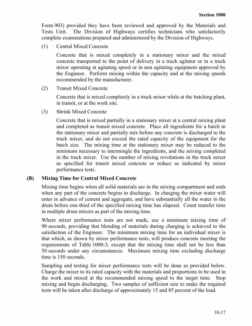
Form 903) provided they have been reviewed and approved by the Materials andTests Unit. The Division of Highways certifies technicians who satisfactorilycomplete examinations prepared and administered by the Division of Highways.(1) Central Mixed Concrete
Concrete that is mixed completely in a stationary mixer and the mixedconcrete transported to the point of delivery in a truck agitator or in a truckmixer operating at agitating speed or in non agitating equipment approved bythe Engineer. Perform mixing within the capacity and at the mixing speedsrecommended by the manufacturer.
(2) Transit Mixed ConcreteConcrete that is mixed completely in a truck mixer while at the batching plant,in transit, or at the work site.
(3) Shrink Mixed ConcreteConcrete that is mixed partially in a stationary mixer at a central mixing plantand completed as transit mixed concrete. Place all ingredients for a batch inthe stationary mixer and partially mix before any concrete is discharged to thetruck mixer, and do not exceed the rated capacity of the equipment for thebatch size. The mixing time at the stationary mixer may be reduced to theminimum necessary to intermingle the ingredients, and the mixing completedin the truck mixer. Use the number of mixing revolutions in the truck mixeras specified for transit mixed concrete or reduce as indicated by mixerperformance tests.
(B) Mixing Time for Central Mixed ConcreteMixing time begins when all solid materials are in the mixing compartment and endswhen any part of the concrete begins to discharge. In charging the mixer water willenter in advance of cement and aggregate, and have substantially all the water in thedrum before one-third of the specified mixing time has elapsed. Count transfer timein multiple drum mixers as part of the mixing time.Where mixer performance tests are not made, use a minimum mixing time of90 seconds, providing that blending of materials during charging is achieved to thesatisfaction of the Engineer. The minimum mixing time for an individual mixer isthat which, as shown by mixer performance tests, will produce concrete meeting therequirements of Table 1000-3, except that the mixing time shall not be less than50 seconds under any circumstances. Maximum mixing time excluding dischargetime is 150 seconds.Sampling and testing for mixer performance tests will be done as provided below.Charge the mixer to its rated capacity with the materials and proportions to be used inthe work and mixed at the recommended mixing speed to the target time. Stopmixing and begin discharging. Two samples of sufficient size to make the requiredtests will be taken after discharge of approximately 15 and 85 percent of the load.

Section 1000
10-18
TABLE 1000-3REQUIREMENTS FOR UNIFORMITY OF CONCRETE
TestsMaximum PermissibleDifference in Test Samples
Air content, percent by volume of Concrete (AASHTO T152) 1.0%
Slump, inches (AASHTO T119) 1.0"
Coarse aggregate content, portion by weight of each sample retained on the No. 4 sieve, percent (AASHTO M157) 6.0%
Weight per cubic foot (AASHTO T121) 1.0 lb.
Average compressive strength at 7 days, percent of average (AASHTO T22 and T23) 10.0%*
* Tentative approval may be granted pending 7 day compressive strength tests.Each of the 2 samples of concrete will be separately tested for the properties listed inTable 1000-3. Tests will be conducted in accordance with the test proceduresspecified in Table 1000-3 or procedures established by the Materials and Tests Unit.
The mixer performance test described above will be performed on a minimum of2 batches of concrete. For the performance test to be acceptable, have all tests ineach batch tested meet the requirements listed above.The Engineer may recheck mixer performance at any time when in his opinionsatisfactory mixing is not being accomplished.Where satisfactory mixing cannot be accomplished in 90 seconds, the Engineer mayincrease the mixing time or require that the mixer be repaired or replaced before anyfurther mixing can be done.
(C) Mixing; Truck Mixers and Truck AgitatorsWhen a truck mixer is used for complete mixing, mix each batch of concrete for atleast 70 revolutions of the drum or blades at the rate of rotation designated by themanufacturer of the equipment as mixing speed, unless otherwise directed by theEngineer. Unless the mixer is equipped with a counter which will distinguishbetween mixing and agitating speeds, perform the minimum required number ofrevolutions of the drum at mixing speed as directed, either at the batching plantbefore the mixer leaves for the work site and/or at the work site before the concrete isdischarged. Perform any additional mixing at the speed designated by the

Section 1000
10-19
manufacturer of the equipment as agitating speed. Put all materials including mixingwater in the drum before actuating the revolution counter for determining the numberof revolutions of the drum.When a truck mixer or truck agitator is used to transport concrete that has beencompletely mixed in a stationary mixer, perform mixing during transport at agitatingspeed.Provide concrete, when discharged from truck mixers or truck agitators, of theconsistency and workability required for the work. Control the rate of discharge ofthe plastic concrete from the mixer drum by the speed or rotation of the drum in thedischarge direction with the discharge gate fully open. If additional mixing water isnecessary to produce the slump necessary for proper placement, perform it only withpermission, and rotate the truck mixer drum a minimum of 25 revolutions at mixingspeed before discharge of any concrete. Additional mixing water will be allowedonly if the maximum specified water content per cubic yard is not exceeded.
(D) DeliveryUse a ticket system for recording the transportation of batches from the proportioningplant to the site of the work. Use tickets furnished by the Engineer and fill it out inaccordance with instructions issued by the Engineer. Issue the tickets to the truckoperator at the proportioning plant for each load and have them signed by the plantinspector, which will signify that the concrete in the truck has been inspected prior todeparture. Have each ticket show the time batching was completed and if transitmixed, the number of revolutions at mixing speed, if any, at the plant. Deliver thetickets to the inspector at the site of the work. Do not use loads which do not carrysuch tickets and loads which do not arrive in satisfactory condition within the timelimits specified in the work.
SECTION 1005GENERAL REQUIREMENTS FOR AGGREGATE
1005-1 GENERALProvide aggregates meeting the applicable requirements of this section except where
otherwise required.Obtain aggregates from sources participating in the Department’s Aggregate Quality
Control/Quality Assurance Program (Aggregate QC/QA program) as described inArticle 1006. Obtain aggregates from pre-approved sources, or have the source approvedprior to use. Approval of such sources is based not only on the quality of the aggregate, butalso on satisfactory production facilities and procedures. A list of approved aggregatesources participating in the Department’s Aggregate Quality Control/Quality AssuranceProgram in North Carolina and adjoining states is available from the Department'sLaboratory in Raleigh. This list includes aggregates meeting Specification requirements butwhose use is restricted due to history of unsatisfactory service performance. Use ofaggregates is allowed in the work provided they have been properly stockpiled in units of

Section 1005
10-20
not less than 300 tons and tests of representative samples of these aggregates indicatesatisfactory compliance with the Specifications and the source meets all the requirements ofthe Aggregate Quality Control/Quality Assurance Program.
Separate aggregate containing rock of more than 1 identifiable rock type or particles ofvisibly different degrees of weathering in amounts of 10 percent or more into eachindividual type. Aggregate is acceptable only if each type does not exceed the percentage ofwear specified for a particular use.
Blended aggregates from different sources is allowed if all aggregates meet theSpecifications for soundness or resistance to abrasion.
For construction of approved stockpiles of non-asphalt type bases refer to theConstruction Manual.1005-2 HANDLING AND STORING AGGREGATES
Handle and stockpile aggregates in such a manner to minimize segregation.Provide sites for aggregate stockpiles that are cleared, grubbed, and cleaned with a firm,
smooth, and well drained ground surface. Maintain a cover of at least 3" of aggregate overthe ground surface to avoid the inclusion of soil or foreign material. Operate trucks or otherequipment on a stockpile in an acceptable manner.
Space or separate with suitable walls or partitions stockpiles of different types or sizes ofaggregates to prevent the mixing of the aggregates. Identify stockpiles with signs that canbe read from a distance of at least 50 feet from the pile.
Do not allow the stockpile to become contaminated with foreign matter or degradeexcessively. Failure of aggregate samples to meet all gradation requirements due toexcessive degradation will be determined by sieve tests of samples taken from any portionof the stockpile and is cause for discontinuance of such stockpiling procedure.1005-3 GRADATION
Grade all standard sizes of aggregate to meet the requirements of Table 1005-1 orTable 1005-2. Comparison of individual Producer Quality Control Samples and thecorresponding Department Quality Assurance Sample shall meet the requirements ofTable 1005-3 or Table 1005-4 as described in the Aggregate QC/QA Program Manual.1005-4 TESTING(A) General
Aggregates will be tested in accordance with the requirements of the Table shownbelow except where other test procedures are required by other articles covering aparticular application.

Section 1005
10-21
TEST TEST METHODGradation AASHTO T27 AND T11;
AASHTO T88 As Modified* For Base Course and Stabilizer
Liquid Limit AASHTO T89 As Modified
Plasticity Index AASHTO T90
Resistance to Abrasion(Percentage of Wear)
AASHTO T96
Soundness AASHTO T104 Using Sodium Sulfate
* Copies of modified test procedures are available from the Materials and Tests Unit

Section 1005
10-22
TABLE 1005-1AGGREGATE GRADATION, COARSE AGGREGATE
PERCENTAGE OF TOTAL BY WEIGHT OF PASSINGSTD.SIZE
#2" 1 1/2" 1" 3/4" 1/2" 3/8" #4 #8 #10 #16 #3
0#40 #50 #80 #100 #200
REMARKS
4 100 90-100
20-55
0-15
0-5
0-*0.6
Asphalt Plant Mix Pavement
467M 100 95-100
35-70
0-30
0-5
0-*0.6
Asphalt Plant Mix Pavement
5 100 90-100
20-55
0-10
0-5
0-*0.6
AST Mat coat, SedimentControl Stone
57 100 95-100
25-60
0-10
0-5
0-*0.6
Str. Conc., Shoulder Drain,Sediment Control Stone
57M 100 95-100
25-45
0-10
0-5
0-*0.6
P. C. Concrete Pavement
6M 100 90-100
20-55
0-20
0-8
* AST
67 100 90-100
20-55
0-10
0-5
0-*0.6
Str. Conc., Asphalt PlantMix Pavement.
78M 100 98-100
75-100
20-45
0-15
0-*0.6
Asphalt Plant Mix Pavement,AST Weep Hole Drains,
Str. Concrete14M 100 35-
705-20
0-8
* * AST
ABC 100 75-97
55-80
35-55
25-45
14-30
4-12**
Aggregate. StabilizationAggregate/Base Course
Asphalt Plant Mix PavementABC(
M)100 75-
10045-79
20- 40 0-25
0-12**
Maintenance Stabilization

Section 1005
10-23
*When these sizes of aggregate are used for portland cement concrete, asphalt treatment,and asphalt plant mix, the requirements pertaining to material passing the No. 200 sieve are asfollows:(A) When tested during production, do not have the amount of material passing through the
No. 200 sieve be more than 0.6% by weight.(B) When tested in a stockpile at the quarry site, do not have the amount of material passing
through the No. 200 sieve be more than 1.0% by weight and use material that consistsmainly of rock dust produced through normal handling of the aggregate.
(C) When tested at the job site prior to use, the amount of material passing the No. 200 sieveshall:(1) Be not greater than 1.5% for coarse aggregate used in portland cement concrete or
asphalt surface treatment.(2) Be not greater than 2.0% for coarse aggregate used in asphalt plant mix.(3) Consist essentially of rock dust produced through normal handling of the aggregate.
(D) If a stockpile at the job site is found to contain in excess of the specified amount ofmaterial passing the No. 200 sieve prior to use, the Engineer may approve its use provided:(1) For coarse aggregate used in portland cement concrete, the total percentage by
weight passing the No. 200 sieve in the combined coarse and fine aggregate in themix does not exceed 2.0%, and provided no increase in water-cement ratio isrequired by the use of this coarse aggregate.
(2) For coarse aggregate used in asphalt plant mix, the total percentage by weight ofminus No. 200 material in the plant mix being produced, as determined by theextraction test, can be maintained within the limits allowed by the job mix formula.
** In addition to the gradation requirements, the material passing the No. 40 sieve shall nothave a liquid limit in excess of 30 nor a plasticity index in excess of 6. For size ABC coarseaggregate used in asphalt plant mix, when tested during production, in a stockpile at thequarry site, or at the job site prior to use, the amount of material passing the No. 200 sieveshall be from 0.0% to 12.0% by weight and the gradation requirements for material passingthe No. 10 sieve (soil mortar) which are shown in Section 1010 for aggregate base course willnot apply. For size ABC coarse aggregate not used in asphalt plant mix, the gradationrequirements for material passing the No. 10 sieve (soil mortar) will be as shown in Section1010, 40-84% passing the No. 40 sieve and 11-35% passing the No. 200 sieve.

Section 1005
TABLE 1005-2AGGREGATE GRADATION FINE AGGREGATE
PERCENTAGE OF TOTAL BY WEIGHT PASSINGSTD.SIZE
#
3/8" #4 #8 #10 #16 #30 #40 #50 #80 #100 #200REMARKS
1S 100 90-100 40-85 0-20 0-3 Blotting Sand, Asphalt Retreatment
2S 100 95-100 80-100 45-95 25-75 5-30 0 .010 0-3 Concrete, Sub-surface Drainage, Blotting Sand
2MS 95-100 80-100 45-95 25-75 5-35 0.-.020 0-*8 Concrete
4S 100 95-100 15-45 0-10 0-5 Mortar
* For Manufactured Fine Aggregate used In portland cement concrete
When tested during production the amount of material passing the No. 200 sieve shall not be greater than 8%. Whentested at the job site prior to use, the amount of material passing the No. 200 sieve shall not be greater than 10% andshall consist of the dust of fracture, and be essentially free from clay or shale. The minimum percent shown for materialpassing the No. 50 and No. 100 sieves may be reduced to 5 and 0, respectively, if the aggregate is to be used in air-entrained concrete containing more than 400 pounds of cementitious material per cubic yard or in non-air entrainedconcrete containing more than 500 pounds of cementitious material per cubic yard or as subdrain fine aggregate.
10-24

Section 1005
10-2525
Table 1005-3Tolerances for Comparisons of Coarse Aggregate QC/QA Gradations
Sieve Sizes ABC #4 #467M #5 #57#57M
#6 #14M #67 #78M
2"1 1/2" +/- 2 +/- 2 +/- 2
1" +/- 4 +/- 4 +/- 2 +/- 3 +/- 23/4" +/- 4 +/- 5 +/- 5 +/- 3 +/- 3 +/- 21/2" +/- 5 +/- 2 +/- 5 +/- 4 +/- 33/8" +/- 2 +/- 3 +/- 2 +/- 4 +/- 3 +/- 5 +/- 3#4 +/- 6 +/- 2 +/- 3 +/- 2 +/- 5 +/- 3 +/- 5#8 +/- 3 +/- 5 +/- 3 +/- 3
#10 +/- 5#40 +/- 5#80
#200 +/- 3 +/- 0.5 +/- 0.5 +/- 0.5 +/- 0.5 +/- 0.5 +/- 0.5 +/- 0.5 +/- 0.5Soil Mortar
#40 +/- 6#200 +/- 5LL +/- 4

Section 1005
10-26
Table 1005-4Tolerances for Comparisons of Fine Aggregate QC/QA Gradations
SieveSizes
DryScreenings
WashedScreenings
AsphaltSand
1S 2S 2MS 4S
1/2"3/8"#4 +/- 2 +/- 2 +/- 2#8 +/- 6 +/- 6 +/- 6 +/- 1 +/- 1 +/- 1 +/- 2
#10#16 +/- 3 +/- 3 +/- 3 +/- 3#30 +/- 3 +/- 3 +/- 3 +/- 3#40 +/- 6 +/- 6 +/- 6#50 +/- 2 +/- 2 +/- 2 +/- 3#80 +/-4 +/-4 +/-4
#100 +/- 1 +/- 1 +/- 1 +/- 2#200 +/- 2 +/- 2 +/- 2 +/- 1 +/- 1 +/- 1 +/- 1
SECTION 1006AGGREGATE QUALITY CONTROL/QUALITY ASSURANCE
1006-1 GENERAL DESCRIPTIONThe Aggregate Quality Control/Quality Assurance Program is designed to give
aggregate producers more responsibility for controlling the quality of material they produceand to utilize the quality control information they provide in the acceptance process by theDepartment. It requires aggregate producers to perform quality control sampling, testingand record keeping on aggregates they ship for use by the Department. Also, it requires theDepartment to perform quality assurance sampling, testing and record keeping confirmingthe performance of the producers' control plan. The program is described in the AggregateQuality Control/Quality Assurance Program Manual. The program has two levels.
Section I of the program is designed for Aggregate Producers providing Clean Coarse orFine Aggregates for use on or in products such as asphalt, concrete, block, etc., that areutilized on the Department’s right of way. Asphalt sand that is produced by and utilized bythe same asphalt producer shall be tested according to the requirements of the Hot MixAsphalt Quality Management System Manual.
Section II of this program is designed for Aggregate Producers providing any type ofAggregate Base, including Cement Treated, material that is utilized on any type of theDepartment’s Maintenance or Contract projects whether purchased by a Contractor or solddirectly to the Department.
The types of samples and the lot sizes required by both levels are described in detail inthe Aggregate Quality Control/Quality Assurance Program Manual and in other sections ofthe Specifications.
It is the intent of the program that acceptance or rejection of material be based on thetotal program. Therefore, a comparison of the Quality Control, Quality Assurance, and

Section 1006
10-27
other sample data may be used by the Department for acceptance or rejection of a lot ofmaterial.
Participation in this program does not relieve the producer of the responsibility ofcomplying with all requirements of the Department’s Specifications.1006-2 PROGRAM REQUIREMENTS(A) Basic Requirements
There are three basic requirements for approval:(1) The plant shall have an approved in-house quality control plan.(2) --- The plant shall have a certified laboratory or have written approval to utilize a
certified laboratory at another plant.(3) --- The plant shall have a certified quality control technician.
(B) Quality Control PlanThe Producer shall prepare a written quality control plan. The plan may be generic,but shall be site specific. The plan shall indicate in detail how the Producer proposesto control the equipment, materials, and production methods to insure that thespecified products are obtained. The plan shall list the personnel responsible forproduction and quality control at the site and include information on how to contacteach person. The following specific information shall also be included in the plan:(1) Identification of the physical location of the source, to include a description of
the property site and reference to the nearest identifiable points such ashighways and towns.
(2) The type of sign used to identify each stockpile or bin identifying it asintended for Department usage.
(3) A loading and shipping control plan which includes a description of themethods by which the products are to be loaded and shipped for use by theDepartment, including safeguards against loading improper aggregate,contamination, degradation, and segregation of the aggregate. The plan shallalso include methods of insuring that all products are accurately identified andthat all shipping units are clean.
(4) A plan for dealing with quality control sample failures. This plan shallinclude how the Producer plans to initiate an immediate investigation and howthe Producer will implement corrective action to remedy the cause of theproblem.
(C) Certified LaboratoryThe Program requires all tests to be conducted at laboratories certified by theDepartment. It is expected that each source, including distribution yards, willestablish and maintain its own laboratory for the performance of quality controltesting, but the Department will consider a producer's request to utilize a certified

Section 1005
10-28
laboratory at one of their other sources in the same general vicinity. The Producershall make this request in writing and have written Department approval beforetesting aggregates off site. The equipment required for a certified laboratory is listedin the Aggregate QC/QA Program Manual. Records on instrument calibration andmaintenance and sample collection and analysis shall be maintained at the laboratory.The Department may require a demonstration of the equipment.
(D) Quality Control TechnicianAll samples shall be taken and tested by quality control technicians certified by theDepartment. The Producer shall designate and identify the quality controltechnicians responsible at each plant. It is imperative that Department sampling andtesting procedures be followed and that Department approved equipment be used inorder to reduce the number of possible causes of differences between the producer'squality control results and the Department's quality assurance results.
(E) Plant Approval Process
The approval process requires the Producer to write the State Materials Engineer atNCDOT Materials and Tests Unit, 1801 Blue Ridge Road, Raleigh, NC 27607,requesting the plant be considered for acceptance into the program. The letter shallidentify the specific products that are to be produced. Two copies of the Producer'swritten quality control plan shall be submitted with the request for approval.A source shall be on the Department Approved Source List before it will beconsidered for approval for the QC/QA Program.The Department will review the Producer's written quality control plan and if it isapproved, an on-site inspection will be scheduled. This on-site inspection will verifythat the Producer's quality control plan has been implemented and is being followedand that at least one certified quality control technician is on site and will be presentwhen material is being shipped under this program. The laboratory will be inspectedand certified if it meets the requirements and has not already been certified. If eitherthe Producer's quality control plan or laboratory do not meet Departmentrequirements, the Producer will be informed of the deficiencies in writing. Once thedeficiencies have been addressed, the Producer may again request approval in writingto the State Materials Engineer.
(F) Certification for Participation in the Aggregate QC/QA ProgramIf the Department has approved the Producer's written quality control plan and theon-site inspection confirms that the initial program requirements have been met, theDepartment will certify the plant for participation in the program. At the end of theyear, and each subsequent year after receipt of the Plant Ownership Update, theDepartment will conduct another on-site inspection and if all requirements arecontinuing to be met, the plant will be recertified for participation in the program foranother year. Random inspections may be conducted at any time by the Departmentto verify compliance with the program requirements.

Section 1006
10-29
A copy of the Plant Ownership Update Form shall be submitted by October 31st ofeach year.
SECTION 1008AGGREGATE BASE COURSE FOR STABILIZATION
1008-1 AGGREGATE STABILIZATION(A) General
Aggregates consist of crushed stone, crushed or uncrushed gravel, or other similarmaterial having hard, strong, durable particles free of adherent coatings.The Contractor may, at his option, furnish aggregates directly to the road or froma stockpile.Supply aggregates from approved sources participating in the Department’sAggregate Quality Control/Quality Assurance Program (Aggregate QC/QA Program)in accordance with the requirements of Sections 1005 and 1006. Sources will not beapproved unless the material has satisfactory soundness and satisfactory resistance toabrasion. Satisfactory soundness will be considered to be a loss in weight of notgreater than 15 percent when subject to 5 alternations of the soundness test.Satisfactory resistance to abrasion will be considered to be a percentage of wear ofnot greater than 55 percent.
(B) Sampling and AcceptanceSampling and acceptance for the determination of gradation, liquid limit, andplasticity index will be performed as provided in Subarticle 1008-1(D).
(C) TestingQuality Control Samples will be tested at a Department Certified Laboratoryaccording to the Aggregate QC/QA Program Manual. Assurance Samples will betested at a Department laboratory.
(D) Department Roadway Assurance SamplingFor sampling and acceptance purposes, a lot will be 5,000 tons or fraction thereof.For each lot of aggregate delivered to the project, 2 samples will be taken at randomintervals. The first sample will be taken from the first 2,500 tons or first half of thelot; the second sample will be taken from the second 2,500 tons or second half of thelot. The gradation test results of these samples will be averaged and the average willbe used to determine the acceptability of the lot.It is intended that the gradation of aggregates be in the middle of the range shown inColumn B of Table 1008-1. If, however, the average test results for a lot are withinthe limits shown in Column B of Table 1008-1, the gradation of the lot will beconsidered as acceptable.

Section 1008
10-30
TABLE 1008-1AGGREGATE BASE COURSE FOR STABILIZATION
GRADATION ACCEPTANCE CRITERIA
Column A
Sieve Size
Column B
% Passingl 1/2" 1001" 72-1001/2" 51-83No. 4 35-60No. 10 20-50No. 40 10-34No. 200 3-13
Material Passing No. 40 SieveL. L. 0-30P. I. 0-6
When the average test results for a lot exceeds any of the limits shown in Column Bof Table 1008-1, the lot will be rejected. The rejected lot will be considered foracceptance only after corrective material has been furnished, placed, and mixed withthe in place aggregate to an acceptable gradation.The liquid limit and plasticity index requirements for the material passing the No. 40sieve shown in Table 1008-1 is for each individual sample. The results will not beaveraged and if any individual test result indicates a value exceeding theserequirements is cause for rejection of the entire lot.
SECTION 1010AGGREGATE FOR NON-ASPHALT
FLEXIBLE TYPE BASES
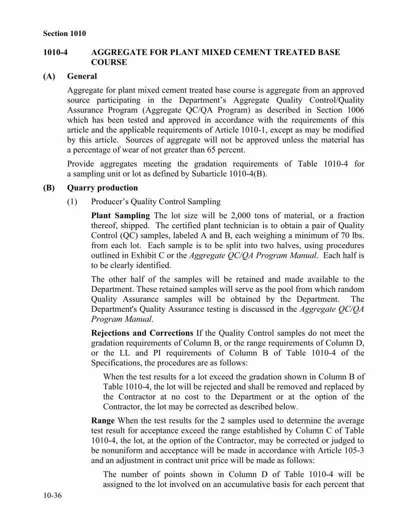
1010-1 AGGREGATE BASE COURSE--GENERAL(A) General Requirements
Aggregate base course material consists of crushed stone, crushed or uncrushedgravel, or other similar material having hard, strong, durable particles free ofadherent coatings.Produce aggregate base course material in accordance with the requirements foraggregate unless otherwise specified in the Specifications.Provide aggregates from approved sources participating in the Department’sAggregate Quality Control/Quality Assurance Program (Aggregate QC/QA Program)in accordance with the requirements of Section 1005 and Section 1006. Sources willnot be approved unless the material has satisfactory soundness and resistance toabrasion. Satisfactory soundness will be considered to be a weighted average loss of

Section 1010
10-31
not greater than 15 percent when subjected to 5 alternations of the soundness test.Satisfactory resistance to abrasion will be considered to be a percentage of wear ofnot greater than 55 percent.
(B) TestingQuality Control Samples will be tested at a Department Certified Laboratoryaccording to the Aggregate QC/QA Program. Assurance Samples will be tested ata Department laboratory.
TABLE 1010-1
AGGREGATE BASE COURSEGRADATION ACCEPTANCE RANGES
Column A Column B% Passing
Column C% Passing
Column DRange
Column E
1 1/2" 100 98-100 3 11" 75-97 72-100 15 1
1/2" 55-80 51-83 20 1# 4 35-55 35-60 18 3
# 10 25-45 20-50 18 2# 40 14-30 10-34 14 3
# 200 4-12 3-13 7 5
Material Passing No. 10 Sieve (Soil Mortar)# 40 40-84 36-86 35 2
# 200 11-35 10-36 20 2Material Passing No. 40 Sieve
L. L. 0-30 0-30 -- --P. I. 0-6 0-6 -- --
1010-2 AGGREGATE BASE COURSEAggregate Base Course is aggregate upon which no restrictions are placed on production
or stockpiling except as provided for in Sections 1005 and 1006.(A) Producer’s Quality Control Sampling
Plant Sampling The lot size for ABC will be 2,000 tons of material, or a fractionthereof, shipped. The certified plant technician is to obtain a pair of Quality Control(QC) samples, labeled A and B, each weighing a minimum of 70 lbs. from each lot ofABC. Each sample is to be split into two halves, using procedures outlined inExhibit C of the Aggregate QC/QA Program Manual. Each half is to be clearlyidentified.The other half of the samples will be retained and made available to the Department.These retained samples will serve as the pool from which random Quality Assurancesamples will be obtained by the Department. The Department's Quality Assurancetesting is discussed in the Aggregate QC/QA Program Manual.

Section 1010
10-32
Price Reductions and Corrections If the Quality Control samples do not meet thegradation requirements of Column B, or the range requirements of Column D, or theLL and PI requirements of Column B of Table 1010-1 of the Specifications, theprocedures are as followsGradation For the lot to be acceptable, the average test results shall meet thegradation requirements shown in Column B of Table 1010-1. When the average testresult exceeds the gradation limits given in Column B but falls within the limitsgiven in Column C, the lot will be rejected and shall be removed and replaced by theContractor, or at the option of the Contractor, the lot may be left in place and thematerial will be considered as being reasonably acceptable in accordance with therequirements of Article 105-3, and an adjustment in contract unit price will be madeas follows:The number of points shown in Column E of Table 1010-1 will be assigned to the lotinvolved on an accumulative basis for each percent that the base material is outsidethe gradation range shown in Column B. Price adjustments will be made byreducing the contract unit price by 2 percent for each point assigned. The unit priceadjustment for average gradation will be in addition to any price adjustmentdetermined necessary for nonuniform base material (range).When the test results for a lot exceed the gradation shown in Column C of Table1010-1, the lot will be rejected and shall be removed and replaced by the Contractorat no cost to the Department or at the option of the Contractor, the lot may becorrected as described below.Range When the test results for the 2 samples used to determine the average testresult for acceptance exceed the range established by Column D of Table 1010-1, thelot, at the option of the Contractor, may be corrected or judged to be nonuniform andacceptance will be made in accordance with Article 105-3 and an adjustment incontract unit price will be made as follows:The number of points shown in Column E of Table 1010-1 will be assigned to the lotinvolved on an accumulative basis for each percent that the range between the testresults of the 2 samples exceeds those values given in Column D. Price adjustmentswill be made by reducing the contract unit price by 2 percent for each point assigned.The unit price adjustment for nonuniform base material will be in addition to anyprice adjustment determined necessary for average gradation (gradation).LL/PI In addition to the gradation acceptance requirements listed in Table 1010-1,the material passing the No. 40 sieve shall not have a Liquid Limit in excess of 30 ora plasticity index in excess of 6. If any individual test result indicates valuesexceeding these, the lot will be rejected and shall be removed and replaced by theContractor.Total Points Any lot having an assigned accumulative gradation and range total ofmore than 25 points will be rejected and shall be removed and replaced by the
Section 1010
10-33
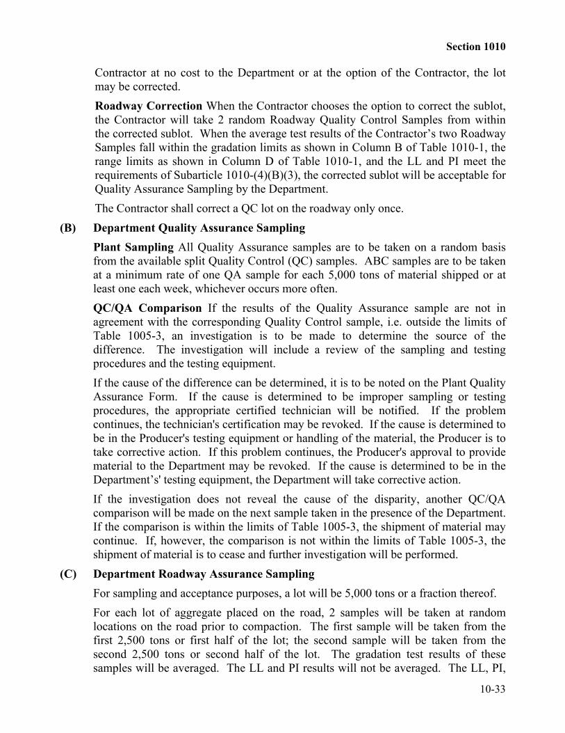
Contractor at no cost to the Department or at the option of the Contractor, the lotmay be corrected.Roadway Correction When the Contractor chooses the option to correct the sublot,the Contractor will take 2 random Roadway Quality Control Samples from withinthe corrected sublot. When the average test results of the Contractor’s two RoadwaySamples fall within the gradation limits as shown in Column B of Table 1010-1, therange limits as shown in Column D of Table 1010-1, and the LL and PI meet therequirements of Subarticle 1010-(4)(B)(3), the corrected sublot will be acceptable forQuality Assurance Sampling by the Department.The Contractor shall correct a QC lot on the roadway only once.
(B) Department Quality Assurance SamplingPlant Sampling All Quality Assurance samples are to be taken on a random basisfrom the available split Quality Control (QC) samples. ABC samples are to be takenat a minimum rate of one QA sample for each 5,000 tons of material shipped or atleast one each week, whichever occurs more often.QC/QA Comparison If the results of the Quality Assurance sample are not inagreement with the corresponding Quality Control sample, i.e. outside the limits ofTable 1005-3, an investigation is to be made to determine the source of thedifference. The investigation will include a review of the sampling and testingprocedures and the testing equipment.If the cause of the difference can be determined, it is to be noted on the Plant QualityAssurance Form. If the cause is determined to be improper sampling or testingprocedures, the appropriate certified technician will be notified. If the problemcontinues, the technician's certification may be revoked. If the cause is determined tobe in the Producer's testing equipment or handling of the material, the Producer is totake corrective action. If this problem continues, the Producer's approval to providematerial to the Department may be revoked. If the cause is determined to be in theDepartment’s' testing equipment, the Department will take corrective action.If the investigation does not reveal the cause of the disparity, another QC/QAcomparison will be made on the next sample taken in the presence of the Department.If the comparison is within the limits of Table 1005-3, the shipment of material maycontinue. If, however, the comparison is not within the limits of Table 1005-3, theshipment of material is to cease and further investigation will be performed.
(C) Department Roadway Assurance SamplingFor sampling and acceptance purposes, a lot will be 5,000 tons or a fraction thereof.For each lot of aggregate placed on the road, 2 samples will be taken at randomlocations on the road prior to compaction. The first sample will be taken from thefirst 2,500 tons or first half of the lot; the second sample will be taken from thesecond 2,500 tons or second half of the lot. The gradation test results of thesesamples will be averaged. The LL and PI results will not be averaged. The LL, PI,

Section 1010
10-34
range, and average gradation results of these samples will be used to determine theacceptability of the lot.LL/PI The material passing the No. 40 sieve shall not have a Liquid Limit in excessof 30 or a Plasticity Index in excess of 6. If any individual test result indicates valuesexceeding these, the lot will be rejected.Range When the test results for the 2 samples used to determine the average testresult for acceptance exceed the range established by Column D of Table 1010-1, thelot, at the option of the Contractor, may be corrected or judged to be nonuniform andacceptance will be made in accordance with Article 105-3 and an adjustment incontract unit price will be made as followsThe number of points shown in Column E of Table 1010-1 will be assigned to the lotinvolved on an accumulative basis for each percent that the range between the testresults of the 2 samples exceeds those values given in Column D. Price adjustmentswill be made by reducing the contract unit price by 2 percent for each point assigned.Any lot having an assigned accumulative range total of more than 25 points will berejected.Gradation For the lot to be acceptable, the average test results shall meet thegradation requirements shown in Column C of Table 1010-1. When the averagegradation test result falls outside the limits of Column C of Table 1010-1, the lot willbe rejected.Check Samples For lots that are rejected, the following steps are to be taken:(1) Perform additional sampling of the 5000 tons of material in order to isolate the
unacceptable material. The procedure for this additional sampling consists ofdividing the 5000 tons of material into two 2500 ton sublots and taking 2samples at random locations from each of these two sublots. The results ofthe 2 samples will be used to determine the acceptance of each of the sublots.
(2) When the test results for a sublot are within the limits above for Range, LL/PI,and Average Gradation, the sublot will be considered acceptable.
(3) When the test results for a sublot exceed any of the limits above for Range,LL/PI, and Average Gradation, and the sublot cannot be corrected by theaddition of aggregate or when the average gradation or range of a correctedsublot exceeds any of the limits of Table 1010-1, Column B or D, or the LL orPI of either sample exceed the limits of Table 1010-1 Column B, the sublotwill be rejected and shall be removed and replaced at no additional cost to theDepartment unless otherwise approved by the Engineer.
(4) When the test results for a sublot exceed any of the limits shown in 3 aboveand the test results indicate the material can be corrected by the addition ofaggregate, the Engineer may allow the material to be corrected provided thereis no additional cost to the Department for furnishing, adding, remixing,reshaping, and recompacting of the added material. The method of correcting

Section 1010
10-35
the sublot shall be approved both by the Area Roadway Engineer and the SoilsEngineer.
(5) Two samples will be randomly taken from the corrected sublot. When theaverage gradation or range of a corrected sublot exceeds any of the limits ofTable 1010-1, Column B or D, or the LL or PI of either sample exceed thelimits of Table 1010-1 Column B, the material will be removed and replacedat no additional cost to the Department in accordance with the requirements ofArticle 520-6.
1010-3 SOIL TYPE BASE COURSE.Soil type base course consists of one or more natural materials proportioned and blended
on the road, and will be Type A, B, or C. Use the type specified in the Specifications.Provide soil type base course free from vegetative matter and lumps or balls of clay
meeting the requirements of Table 1010-3 for the applicable type.Samples will be taken in accordance with Article 530-8.
TABLE 1010-3ACCEPTANCE CRITERIA FOR
SOIL TYPE BASE COURSE
Sieve Size Type A Type B Type C% Passing % Passing % Passing
2" -- 100% --1" 100% 70-100% 100%
1/2" -- 55-100% --No. 4 -- 35-80% --No. 10 65-100% 25-65% 65-100%No. 40 -- 15-45%* --No. 200 -- 5-25%* --
Material Passing No. 10 Sieve (Soil Mortar)No. 40 40-75% -- 40-95%No. 200 12-35% -- 12-35%
Material Passing No. 40 SieveL. L. 0-25 0-25 0-25P. I. 0-6 0-6 0-6
* The fraction passing the No. 200 sieve shall be less than 2/3 the fraction passingthe No. 40 sieve.
Section 1010
10-36
1010-4 AGGREGATE FOR PLANT MIXED CEMENT TREATED BASECOURSE
(A) GeneralAggregate for plant mixed cement treated base course is aggregate from an approvedsource participating in the Department’s Aggregate Quality Control/QualityAssurance Program (Aggregate QC/QA Program) as described in Section 1006which has been tested and approved in accordance with the requirements of thisarticle and the applicable requirements of Article 1010-1, except as may be modifiedby this article. Sources of aggregate will not be approved unless the material hasa percentage of wear of not greater than 65 percent.Provide aggregates meeting the gradation requirements of Table 1010-4 fora sampling unit or lot as defined by Subarticle 1010-4(B).
(B) Quarry production(1) Producer’s Quality Control Sampling
Plant Sampling The lot size will be 2,000 tons of material, or a fractionthereof, shipped. The certified plant technician is to obtain a pair of QualityControl (QC) samples, labeled A and B, each weighing a minimum of 70 lbs.from each lot. Each sample is to be split into two halves, using proceduresoutlined in Exhibit C or the Aggregate QC/QA Program Manual. Each half isto be clearly identified.The other half of the samples will be retained and made available to theDepartment. These retained samples will serve as the pool from which randomQuality Assurance samples will be obtained by the Department. TheDepartment's Quality Assurance testing is discussed in the Aggregate QC/QAProgram Manual.Rejections and Corrections If the Quality Control samples do not meet thegradation requirements of Column B, or the range requirements of Column D,or the LL and PI requirements of Column B of Table 1010-4 of theSpecifications, the procedures are as follows:
When the test results for a lot exceed the gradation shown in Column B ofTable 1010-4, the lot will be rejected and shall be removed and replaced bythe Contractor at no cost to the Department or at the option of theContractor, the lot may be corrected as described below.
Range When the test results for the 2 samples used to determine the averagetest result for acceptance exceed the range established by Column C of Table1010-4, the lot, at the option of the Contractor, may be corrected or judged tobe nonuniform and acceptance will be made in accordance with Article 105-3and an adjustment in contract unit price will be made as follows:
The number of points shown in Column D of Table 1010-4 will beassigned to the lot involved on an accumulative basis for each percent that

Section 1010
10-37
the range between the test results of the 2 samples exceeds those valuesgiven in Column C. Price adjustments will be made by reducing thecontract unit price by 2 percent for each point assigned. The unit priceadjustment for nonuniform material will be in addition to any priceadjustment determined necessary for average gradation.
LL/PI In addition to the gradation acceptance requirements listed in Table1010-4, the material passing the No. 40 sieve shall not have a Liquid Limit inexcess of 30 or a plasticity index in excess of 4. If any individual test resultindicates values exceeding these, the lot will be rejected and shall be removedand replaced by the Contractor.Total Points Any lot having an assigned accumulative gradation and rangetotal of more than 25 points will be rejected and shall be removed andreplaced by the Contractor at no cost to the Department or at the option of theContractor, the lot may be corrected.Roadway Correction When the Contractor chooses the option to correct thesublot, the Contractor will take 2 random Roadway Quality Control Samplesfrom within the corrected sublot. When the average test results of theContractor’s two Roadway Samples fall within the gradation limits as shownin Column B of Table 1010-4, the range limits as shown in Column D ofTable 1010-4, and the LL and PI meet the requirements of Column B of Table1010-4, the corrected sublot will be acceptable for Quality AssuranceSampling by the Department.The Contractor is only allowed to correct a QC lot on the roadway once.
(2) Department Quality Assurance SamplingPlant Sampling Take all Quality Assurance samples on a random basis fromthe available split Quality Control (QC) samples. Take them at a minimumrate of one QA sample for each 5,000 tons of material shipped or at least oneeach week, whichever occurs more often.QC/QA Comparison - If the results of the Quality Assurance sample are notin agreement with the corresponding Quality Control sample, i.e. outside thelimits of Table 1005-3, an investigation is to be made to determine the sourceof the difference. The investigation will include a review of the sampling andtesting procedures and the testing equipment.If the cause of the difference can be determined, it is to be noted on the PlantQuality Assurance Form. If the cause is determined to be improper samplingor testing procedures, the appropriate certified technician will be notified. Ifthe problem continues, the technician's certification may be revoked. If thecause is determined to be in the Producer's testing equipment or handling ofthe material the Producer is to take corrective action. If this problemcontinues, the Producer's approval to provide material to Department may be

Section 1010
10-38
revoked. If the cause is determined to be in the Department's testingequipment, the Department will take corrective action.If the investigation does not reveal the cause of the disparity, another QC/QAcomparison will be made on the next sample taken in the presence of theDepartment. If the comparison is within the limits of Table 1005-3, theshipment of material may continue. If, however, the comparison is not withinthe limits of Table 1005-3, the shipment of material is to cease and furtherinvestigation will be performed.
(3) Department Roadway Assurance SamplingFor sampling and acceptance purposes, a lot will be 5,000 tons or a fractionthereof.For each lot of aggregate placed on the road, 2 samples will be taken atrandom from the pugmill belt or roadway prior to the cement being added.The first sample will be taken from the first 2,500 tons or first half of the lot;the second sample will be taken from the second 2,500 tons or second half ofthe lot. The gradation test results of these samples will be averaged. The LLand PI results will not be averaged. The LL, PI, range, and average gradationresults of these samples will be used to determine the acceptability of the lot.LL/PI The material passing the No. 40 sieve shall not have a Liquid Limit inexcess of 30 or a Plasticity Index in excess of 4. If any individual test resultindicates values exceeding these, the lot will be rejected.Range When the test results for the 2 samples used to determine the averagegradation test result for acceptance exceed the range established by Column Cof Table 1010-4, the lot will be judged to be nonuniform and an adjustment incontract unit price will be made as follows:The number of points shown in Column D of Table 1010-4 will be assigned tothe lot involved on an accumulative basis for each percent that the rangebetween the test results of the 2 samples exceeds those values given inColumn C. Price adjustments will be made by reducing the contract unit priceby 2 percent for each point assigned. Any lot having an assignedaccumulative range total of more than 25 points will be rejected.Check Samples of the material may be taken by the Engineer in accordancewith the procedures listed below if cement has not yet been added.Gradation For the lot to be acceptable, the average test results shall meet thegradation requirements shown in Column B of Table 1010-4. When theaverage gradation test result falls outside the limits of Column B ofTable 1010-4, the lot will be rejected.Check Samples For lots that are rejected, the following steps are to be takenif cement has not yet been added to the material:

Section 1010
10-39
(a) Perform additional sampling of the 5000 tons of material in order toisolate the unacceptable material. The procedure for this additionalsampling consists of dividing the 5000 tons of material into two 2500ton sublots and taking 2 samples at random locations from each ofthese two sublots. The results of the 2 samples will used to determinethe acceptance of each of the sublots.
(b) When the test results for a sublot are within the limits above for Range,LL/PI, and Average Gradation, the sublot will be consideredacceptable.
(c) When the test results for a sublot exceed any of the limits above forRange, LL/PI, and Average Gradation, and the sublot cannot becorrected by the addition of aggregate or when the average gradation orrange of a corrected sublot exceeds any of the limits of Table 1010-4,Column B, or the LL or PI of either sample exceed the limits of Table1010-4 Column B, the sublot will be rejected and shall be removed andreplaced at no additional cost to the Department unless otherwiseapproved by the Engineer.
(d) When the test results for a sublot exceed any of the limits shown aboveand the test results indicate the material can be corrected by theaddition of aggregate, the Engineer may allow the material to becorrected provided there is no additional cost to the Department forfurnishing, adding, remixing, reshaping, and recompacting of the addedmaterial. The method of correcting the sublot shall be approved bothby the Area Roadway Engineer and the Soils Engineer.
(e) Two samples will be randomly taken from the corrected sublot. Whenthe average gradation or range of a corrected sublot exceeds any of thelimits of Table 1010-4, Column B, or the LL or PI of either sampleexceed the limits of Table 1010-4 Column B, the material will beremoved and replaced at no additional cost to the Department inaccordance with the requirements of Subarticle 520-6(B).
TABLE 1010-4ACCEPTANCE CRITERIA FOR
AGGREGATE FOR PORTLAND CEMENT TREATED BASE COURSEColumn A
SieveColumn B Column C
RangeColumn D
Points1 1/2" 100% 3 1
1" 80-100% 15 11/2" 58-83% 20 1
No. 4 38-60% 18 3No. 10 28-50% 18 2No. 40 15-33% 14 3No. 200 6-13% 7 5

Section 1010
10-40
Material Passing No. 10 Sieve (Soil Mortar)No. 40 40-85% 35 2No. 200 12-35% 20 2
Material Passing No. 40 SieveL. L. 0-30 -P. I. 0-4 -
SECTION 1012AGGREGATE FOR ASPHALT PAVEMENTS AND SURFACE
TREATMENTS
1012-1 AGGREGATES FOR ASPHALT PLANT MIXES(A) General
Formulate the asphalt plant mix with coarse and fine aggregate that meets therequirements of Section 1005, except as noted herein. Size, uniformly grade, andcombine the several aggregate fractions in such proportions that the resulting mixturemeets the grading and physical requirements of these Specifications for the specifiedmix type. Materials that will not produce a mixture within the design criteriarequired by these Specifications will be rejected, unless otherwise approved.The consensus property criteria in Table 1012-1 apply to the coarse aggregate or fineaggregate blend. Source property criteria apply to individual aggregate sources.For all surface course mixes, except OGAFC, that are the top or final layer, limit theamount of coarse aggregate or fine aggregate produced from crystalline limestone,crystalline-dolomitic limestone, or marble to a maximum of 50% of the total amountof coarse aggregate or fine aggregate in the asphalt mixture. Do not use aggregatesproduced from crystalline limestone, crystalline-dolomitic limestone, or marble in theproduction of open-graded asphalt friction course.
(B) Coarse Aggregate(1) General
Use coarse aggregate consisting of crushed stone, crushed gravel, a mixture ofuncrushed gravel with either crushed stone or crushed gravel, or other inertmaterial having similar characteristics. Provide coarse aggregate composed ofclean, tough, durable fragments free from an excess of flat or elongatedpieces, and free of organic matter and deleterious substances.Use coarse aggregate from sources participating in the Department’sAggregate Quality Control/Quality Assurance (QC/QA) Program as describedin Section 1006. A list of sources participating in the Department’s QC/QAProgram in North Carolina and adjoining states is available from theDepartment’s Materials and Tests Unit in Raleigh.

Section 1012
10-41
(2) GradationUse standard size coarse aggregate meeting the requirements of Table 1005-1and these Specifications unless otherwise approved.
(3) Coarse Aggregate Angularity (Fractured Faces)Use coarse aggregate meeting the requirements of Table 1012-1 for courseaggregate angularity (fractured faces) when tested in accordance withASTM D 5821.
(4) Flat and Elongated PiecesUse coarse aggregate meeting the requirements of Table 1012-1 for flat andelongated pieces when tested in accordance with ASTM D 4791 (Section 8.4)on the No. 4 sieve and larger with a 5:1 aspect ratio (maximum to minimum)for all pavement types, except there is no requirement for, Types S4.75A,SF9.5A and S 9.5B.
(5) SoundnessThe maximum weighted average soundness loss of individual coarseaggregate sources when subjected to 5 cycles using sodium sulfate whentested in accordance with AASHTO T 104 is 15%.
TABLE 1012-1AGGREGATE CONSENSUS PROPERTIES (a)
Mix Type Course AggregateAngularity(b)
Fine Aggregate Angularity% Minimum
Sand Equivalent% Minimum
Flat &Elongated5 : 1 Ratio % Maximum
ASTMD 5821
AASHTOT304 Method A
AASHTOT 176
ASTM D 4791Section 8.4
S.4.75 40 40SF9.5AS 9.5 , BS 12.5 B 75 / - 40 40 10(c)
I 19.0 BB 25.0 B
S 9.5 CS 12.5 C 95 / 90 45 45 10I 19.0 CB 25.0 CB 37.5 CS 12.5 D 100 / 100 45 50 10I 19.0 DOGAFC 100/100 NA NA NA
Notes (a)Requirements apply to the coarse aggregate blend and/or fine aggregate blend(b) 95/90 denotes that 95% of the coarse aggregate has one fractured face and 90%
has two or more fractured faces.(c) Does not apply to Mix Types S 9.5A and S 9.5B.
(6) Toughness (Resistance to Abrasion)The maximum allowable percentage of loss of each individual coarseaggregate source for all plant mix types except open-graded asphalt friction

Section 1012
10-42
course, when tested in accordance with AASHTO T 96 is 55%. Themaximum percentage loss for aggregate used in OGAFC is 45%.
(7) Deleterious MaterialsThe maximum allowable percentage by weight of clay lumps and friableparticles in individual aggregate sources when tested in accordance withAASHTO T 112 is 0.3%.
(C) Fine Aggregate(1) General
Use fine aggregate that is consistently graded from coarse to fine and consistsof natural sand, stone screenings, or a blend of natural sand and stonescreenings. Use aggregate composed of rough surfaced and angular grains ofquartz or other hard durable rock.Use fine aggregate from sources participating in the Department’s AggregateQuality Control/Quality Assurance (QC/QA) Program as described in Section1006 unless the fine aggregate is produced at a pit owned by the same owneras the asphalt plant where the material is used. A list of sources participatingin the Department’s QC/QA Program in North Carolina and adjoining states isavailable from the Department’s Materials and Tests Unit in Raleigh.Furnish sand from sources that have been approved. Do not use sources thathave been contaminated by industrial waste. A sufficient number of samplesof fine aggregate, but in no case less than three, will be taken to indicate anyvariation within any stockpile or source of supply.Do not use fine aggregate containing sticks, roots, trash, visible lumps of clay,or other unsatisfactory material unless all undesirable material is removed tothe satisfaction of the Engineer before the aggregate is used in the asphaltmixture.Use natural sand that is non-plastic when tested in accordance withAASHTO T 90.Natural sand that contains grains of questionable hardness will be subjected to5 cycles of the soundness test. The weighted average loss shall be not morethan 15 percent. The soundness test will be performed prior to establishingthe mix design.Produce stone screenings from stone that has a maximum percentage of wearof 55 percent when tested in accordance with AASHTO T 96 using testgrading A.

Section 1012
10-43
(2) GradationUse stone screenings that are consistently graded with not more than20 percent by weight passing the No. 200 sieve when tested by dry sieving inaccordance with AASHTO T 27. Use natural sand that is consistently graded.
(3) Clay Content (Sand Equivalent)Use a fine aggregate blend that has a minimum sand equivalent percentage asindicated in Table 1012-1 when tested in accordance with AASHTO T 176.
(4) SoundnessThe maximum weighted average soundness loss of individual fine aggregatesources when subjected to 5 cycles using sodium sulfate when tested inaccordance with AASHTO T 104 is 15%.
(5) Deleterious MaterialsThe maximum percentage by weight of clay lumps and friable particles inindividual fine aggregate sources when tested in accordance with AASHTOT 112 is 0.3 %.
(6) Fine Aggregate AngularityUse a fine aggregate blend that has a minimum fine aggregate angularity asindicated in Table 1012-1 when tested in accordance with AASHTO T 304Method A.
(D) Mineral FillerUse mineral filler consisting of limestone dust, dolomite dust, portland cement, orother inert mineral matter that conforms to the requirements of AASHTO M 17.
(E) Hydrated Lime Anti-strip AdditiveUse hydrated lime conforming to the requirements of ASTM C 977. Add hydratedlime used for anti-strip purposes at a rate of not less than 1.0% by weight of the totaldry aggregate.
(F) Reclaimed Asphalt Shingle Material (RAS)Reclaimed asphalt shingles (RAS) are materials produced as a by-product of themanufacturing process for roofing shingles. Process the RAS by ambient grinding orgranulating methods such that 100% will pass the 1/2" sieve when tested inaccordance with AASHTO T-27. Perform the test on ground asphalt shingles prior toextraction of the asphalt. The use of discarded shingles or shingle scrap from re-roofing of commercial or residential buildings will not be allowed.
(G) Reclaimed Asphalt Pavement (RAP)Use reclaimed asphalt pavement that meets all requirements specified for thefollowing classifications

Section 1012
10-44
(1) MillingsExisting reclaimed asphalt pavement (RAP) that is removed from the originallocation by a milling process as specified in Section 607.
(2) Processed RAPRAP that is processed in some form (possibly by crushing or use of a blendingmethod) to produce a uniform gradation and binder content in the RAP priorto use in a recycled mix. Process RAP so that all materials will pass a 2" sieveprior to introduction into the plant mixer unit. Millings are consideredprocessed provided it has a uniform gradation and binder content and does notcontain oversize material.
(3) Unprocessed RAPRAP in the form as removed from the original location that has not beenprocessed for gradation and binder content uniformity. Different sources ofunprocessed RAP may be stockpiled together provided it is generally free ofcontamination and will be processed prior to use in a recycled mix. RAPcontamination in the form of excessive dirt, debris, clean stone, concrete, etc.will not be allowed. Incidental amounts of dirt, concrete, and clean stone willbe acceptable.
(4) New Source RAPNew source RAP will be classified into 2 categories:(a) Millings from a different source than that of the millings used for the
recycled mix design process, and that are not to be further processed,will be considered a new source RAP.
(b) All processed RAP other than that included in the original stockpilesampled and approved for the recycled mix design will be considereda new source RAP.
After a stockpile of processed RAP or millings has been sampled and mix designsmade from these samples, do not add new source RAP to the original stockpilewithout prior field testing to insure gradation and binder uniformity. New sourceRAP shall be sampled before blending with the existing stockpile.Store new source RAP in a separate stockpile until the material can be sampled andtested for comparison with the original recycled mix design data. New source RAPmay also be placed against the existing stockpile in a linear manner provided it issampled for mix design conformity prior to its use in the recycled mix.Field approval will be based on Table 1012-2 below and volumetric mix propertieson the mix with the new source RAP included. Provided the Table 1012-2 tolerancesare met, volumetric properties of the new mix will then be performed. If allvolumetric mix properties meet the mix design criteria for that mix type, the newsource RAP may continue to be used.

Section 1012
10-45
If the gradation, binder content, or any of the volumetric mix properties are notwithin the allowable tolerances, do not use the new source RAP unless approved bythe Engineer. A decision to not use the stockpile, adjust the JMF, or redesign the mixwill be made.
TABLE 1012-2NEW SOURCE RAP GRADATION and BINDER TOLERANCES
(Apply Tolerances to Mix Design Data)MixType
0-15% RAP 15+-25 % RAP 25+ % RAP
Sieve Base Inter. Surf. Base Inter. Surf. Base Inter. Surf.
Pb, % ± 0.7% ± 0.4% ± 0.3%1 1/2" ±10 - - ±7 - - ±5 - -3/4" ±10 ±10 - ±7 ±7 - ±5 ±5 -1/2" - ±10 ±6 - ±7 ±3 - ±5 ±23/8" - - ±8 - - ±5 - - ±4No. 4 ±10 - ±10 ±7 - ±7 ±5 - ±5No. 8 ±8 ±8 ±8 ±5 ±5 ±5 ±4 ±4 ±4No. 16 ±8 ±8 ±8 ±5 ±5 ±5 ±4 ±4 ±4No. 30 ±8 ±8 ±8 ±5 ±5 ±5 ±4 ±4 ±4No. 50 - - ±8 - - ±5 - - ±4No. 200 ±4 ±4 ±4 ±2 ±2 ±2 ±1.5 ±1.5 ±1.5
1012-2 AGGREGATES FOR ASPHALT SURFACE TREATMENT(A) General
Use coarse aggregate consisting of crushed stone, crushed gravel, crushed slag, orother inert material having similar characteristics. Adequately wash coarse aggregateso that it is free from clay, loam, dust, and other adherent materials.Adequately clean all fine aggregate so that it is free from sticks, roots, visible lumpsof clay, or other unsatisfactory material prior to use.
(B) GradationUse standard size No. 5, No. 67, No. 78M, or Lightweight coarse aggregate for mator seal coat as required by Table 660-1, unless otherwise required by the contract.Use aggregate meeting the applicable gradation requirements of Table 1012-3.Remix aggregate that has become segregated until it meets the applicable gradationrequirements.

Section 1012
10-46
TABLE 1012-3AGGREGATE GRADATION, COARSE AGGREGATE, ASPHALT SURFACE TREATMENT
PERCENTAGE OF TOTAL BY WEIGHT OF PASSINGSTDSIZE
2" 11/2"
1" 3/4"
1/2"
3/8" #4 #8 #10 #16 #30#40#50 #80 #100
#200 REMARKS
5 100
90-100
20-55
0-10
0-5
0-*0.6
AST Mat coat,Sediment ControlStone
67 100
90-100
20-55
0-10 0-5 0-*0.6
AST Mat coat
78M 100
98-100
75-100
20-45
0-15
0-*0.6
Asphalt Plant MixPavement, AST WeepHole Drains, Str.Concrete
LIGHTWEIGHT
100
80-100
5-40 0-20
0-10
0-2.5
AST

Section 1012
10-47
(C) Fractured FacesUse coarse aggregate that contains at least 75 percent by weight of crushed pieceshaving 2 or more fractured faces, and at least 90 percent by weight of crushed pieceshaving 1 or more fractured faces on that portion retained on the No. 4 sieve.
(D) SoundnessThe maximum weighted average loss of either coarse or fine aggregate whensubjected to 5 cycles using sodium sulfate when tested in accordance with AASHTOT 104 is 15%.
(E) Toughness (Resistance to Abrasion)The maximum percentage loss of course aggregate for asphalt surface treatmentwhen tested in accordance with AASHTO T 96 is 55%.
(F) Blending of AggregatesBlending of two or more aggregates will not be permitted regardless of the origin ofthe aggregates if any one of the aggregates fails to meet the requirements forsoundness or resistance to abrasion.
(G) Weight of SlagThe minimum weight of crushed slag is 70 pounds per cubic foot as determined inaccordance with AASHTO T 19.
1012-3 BLOTTING SANDBlotting sand is fine aggregate consisting of natural sand, commercial sand,
manufactured sand, coarse screenings, or other inert material having similar characteristics.The requirements of Subarticles 1012-2 (D) and 1012-2 (F) will be applicable to blottingsand. Adequately clean the fine aggregate so that it is free from sticks, roots, visible lumpsof clay, or other unsatisfactory material prior to use.1012-4 LIGHTWEIGHT AGGREGATE
Lightweight aggregates used in asphalt surface treatments shall be produced by therotary kiln process and shall come from an approved Department source meeting applicablerequirements of Section 1005 and 1006. The aggregate shall also meet the requirements ofASTM C330, Lightweight Aggregate for Structural Concrete (AASHTO M195), with theexception of Sections 3, 6, 8, and any other references to concrete samples or concretestrength. TABLE 1012-4
Lightweight Physical PropertiesProperty Specification (maximum) Test Procedure
Sodium Sulfate Soundness 5% AASHTO T19
Los Angeles Abrasion 45% AASHTO T96 (B grading)
Percent Absorption 10% AASHTO T19
Micro-Deval 18% AASHTO TP58-02

Section 1014
10-48
SECTION 1014AGGREGATE FOR PORTLAND CEMENT
CONCRETE1014-1 FINE AGGREGATE(A) General
Use fine aggregate from sources participating in the Department’s Aggregate QualityControl/Quality Assurance Program as described in Section 1006. A list of sourcesparticipating in the Department’s Quality Control/Quality Assurance Program in NorthCarolina and adjoining states is available from the Department’s Laboratory in Raleigh.Use fine aggregate consisting of natural sand or manufactured sand having clean, durable,hard, uncoated particles, or other inert materials having similar characteristics. Producemanufactured sand from fractured stone material. Use fine aggregate free from dirt,wood, paper, burlap, and all other foreign material.To permit excess water to drain and the moisture content to become uniform, stockpile theaggregates either at the producer's plant or at the batch plant site for at least 24 hoursbefore use in the concrete. Build open stockpiles of fine aggregate at the batch plant onconcrete surfaces. Do not add new material to the stockpile during the 24 hour period.When the aggregates have a low and uniform moisture content and the consistency of theconcrete can be satisfactorily controlled without stockpiling the aggregates for 24 hours,the minimum stockpiling period may be reduced or waived entirely by the Engineer.The Division of Highways' list of approved sources of fine aggregate shows the targetfineness modulus of each aggregate as established by the producer. Do not use fineaggregate with a fineness modulus that varies more than 0.2 from the target value untilthe concrete mix proportions are adjusted.
(B) SoundnessWhen subjected to 5 cycles of the soundness test, the weighted average loss shall not bemore than 15 percent.
(C) Deleterious SubstancesThe amount of deleterious substances shall not exceed the following:
SubstanceMaximum
Permissible PercentageClay Lumps and 2.0 by weight (Natural sand)Friable Particles 1.0 by weight (Manufactured sand)
The percentage of deleterious substances will be determined in accordance withAASHTO T112.

Section 1014
10-49
(D) Organic ImpuritiesThe color of each source of fine aggregate will be determined annually in accordancewith AASHTO T21. Should the fine aggregate show a darker color than samplespreviously approved from the same source, withhold its use until tests have beenmade to determine the quality of the sand.
(E) Mortar StrengthMortar made with the fine aggregate shall have a compressive strength at the age of3 and 7 days using Type III portland cement, or 7 and 28 days using Type I or IIportland cement, of not less than 95 percent of that developed by a comparisonmortar. Make the comparison mortar with the same cement, graded Ottawa sandwith a fineness modulus of 2.40 plus or minus 0.05, and the same water-cement ratioand consistency as the test mortar. Test the mortar strength in accordance withAASHTO T 106.Fine aggregate that fails to meet the requirements of the preceding paragraph formortar strength may be used with the approval of the Engineer, provided that when itis tested in concrete cylinders the compressive strength of the concrete at 14 days isequal to or greater than the strength of cylinders made with an identical mix using anacceptable sand.
(F) GradationNatural sand shall meet the gradation requirements for standard size No. 2S fineaggregate. Manufactured sand shall meet the gradation requirements for standardsize No. 2MS fine aggregate.
(G) Blending Fine AggregateBlending fine aggregates to obtain the required gradation will be permitted if testresults of each aggregate meet the durability requirements and test results of thecombination indicate acceptable quality. Blend aggregates by weighing themseparately at the time of batching or by other means acceptable to the Engineer.When natural sand is blended with natural sand, the blend shall meet the gradationrequirements for No. 2S fine aggregate. When manufactured sand is blended withnatural sand or with manufactured sand, the blend shall meet the gradationrequirements for No. 2MS fine aggregate and neither component can exceed thegradation limits on the No. 200 sieve shown in Table 1005-2.
(H) Siliceous Particle ContentManufactured sand shall have a siliceous particle content of not less than 25 percentwhen used in concrete surfaces exposed to traffic. The siliceous particle content willbe determined by NCDOT Chemical Procedure C-9. Copies of this test procedureare available upon request from the Materials and Tests Unit.

Section 1014\
10-50
1014-2 COARSE AGGREGATE(A) General
Use coarse aggregate from sources participating in the Department’s AggregateQuality Control/Quality Assurance Program as described in Section 1006. A list ofthese sources in North Carolina and adjoining states is available from the Materialsand Tests Unit in Raleigh.Use coarse aggregate that consists of crushed stone, crushed or uncrushed gravel,crushed air-cooled blast furnace slag, or other inert materials that have similarcharacteristics. Wash all coarse aggregate for portland cement concrete to removeclay, loam, dust, and similar adherent materials unless otherwise permitted by theEngineer in writing. Keep coarse aggregate free from dirt, wood, paper, burlap, andall other foreign material.To permit excess water to drain and the moisture content to become uniform,stockpile the aggregates either at the producer's plant or at the batch plant site for atleast 24 hours before use in the concrete. Build open stockpiles of coarse aggregate atthe batch plant on concrete surfaces. Do not add new material to the stockpile duringthe 24 hour period. Where the aggregates have low and uniform moisture contentand the consistency of the concrete can be satisfactorily controlled withoutstockpiling the aggregates for 24 hours, the minimum stockpiling period may bereduced or waived entirely by the Engineer.Do not mix coarse aggregate from different sources or use it in alternate batchesexcept where permitted by the Engineer in writing. Blending of coarse aggregates toobtain the required gradation will be permitted if the different sizes are from thesame source. Blend coarse aggregates by weighing them separately at the time ofbatching or by other means acceptable to the Engineer.
(B) SoundnessWhen subjected to 5 cycles of the soundness test the weighted average loss shall notexceed 15 percent. For concrete with a 28 day design compressive strength greaterthan 6,000 psi, the loss shall not exceed 8%.
(C) Deleterious SubstancesThe amount of deleterious substances shall not exceed the following:
SubstanceMaximum
Permissible PercentageClay Lumps andFriable Particles 3.2 by weight
Determine the percentage of deleterious substances in accordance withAASHTO T112.

Section 1014
10-51
(D) Resistance to AbrasionThe percentage of wear of crushed stone or gravel shall not exceed 55 percent. Forconcrete with a 28 day design strength greater than 6,000 psi, the wear shall notexceed 40%.
(E) Aggregate Sizes(1) General
Use standard size No. 57, No. 67, or No. 78M coarse aggregate in portlandcement concrete unless otherwise indicated.
(2) Latex Modified ConcreteUse standard size No. 78M coarse aggregate in latex modified concrete.
(3) Prestressed and Precast ConcreteUse No. 67 or No. 78M coarse aggregate in prestressed and precast concrete.
(4) Use of More Than One SizeAll concrete used in a single component of any structure shall be made withthe same size aggregate.
(5) Portland Cement Concrete PavementUse standard size No. 57, No. 57M, No. 67, or #78M coarse aggregate inconcrete for portland cement concrete pavement unless otherwise specified bythe Engineer.
(6) Sand Lightweight Concrete Use the following gradation for the lightweightcoarse aggregate:
Sieve Size Passing Square Opening Sieves(Percent by Weight)
1” 1003/4” 90 - 1003/8” 10 - 50No. 4 0 - 15
(F) GradationAll coarse aggregate shall meet the gradation requirements for the standard size used.
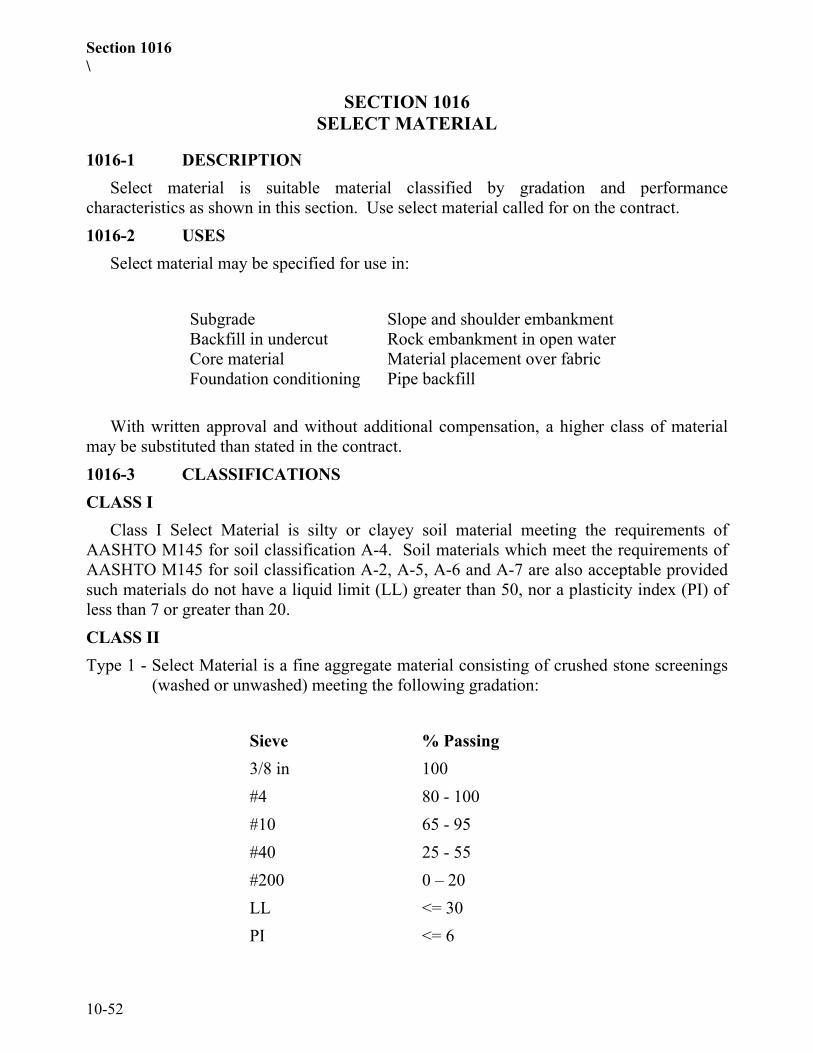
Section 1016\
10-52
SECTION 1016SELECT MATERIAL
1016-1 DESCRIPTIONSelect material is suitable material classified by gradation and performance
characteristics as shown in this section. Use select material called for on the contract.1016-2 USES
Select material may be specified for use in:
Subgrade Slope and shoulder embankmentBackfill in undercut Rock embankment in open waterCore material Material placement over fabricFoundation conditioning Pipe backfill
With written approval and without additional compensation, a higher class of materialmay be substituted than stated in the contract.1016-3 CLASSIFICATIONSCLASS I
Class I Select Material is silty or clayey soil material meeting the requirements ofAASHTO M145 for soil classification A-4. Soil materials which meet the requirements ofAASHTO M145 for soil classification A-2, A-5, A-6 and A-7 are also acceptable providedsuch materials do not have a liquid limit (LL) greater than 50, nor a plasticity index (PI) ofless than 7 or greater than 20.CLASS IIType 1 - Select Material is a fine aggregate material consisting of crushed stone screenings
(washed or unwashed) meeting the following gradation:
Sieve % Passing3/8 in 100#4 80 - 100#10 65 - 95#40 25 - 55#200 0 – 20LL <= 30PI <= 6

Section 1016
10-53
Type 2 - Select Material is a granular soil material meeting the requirements ofAASHTO M145 for soil classifications A-2-4 with a maximum PI of 6 and A-4soil containing 45% maximum passing a No. 200 sieve and a maximum PI of 6.
When a type is not specified, either type may be used, but no additional compensationwill be made.CLASS IIIType 1 - Select Material is a natural or manufactured fine aggregate material meeting the
gradation requirements of standard size 2S or 2MS in Table 1005-2 as described inSections 1005 and 1006.
Type 2 - Select Material is a granular soil material meeting the requirements of AASHTOM145 for soil classification A-1 or A-3.
When a type is not specified, either type may be used, but no additional compensationwill be made.CLASS IV
Select Material is a coarse aggregate material meeting the gradation requirements ofstandard size ABC as described in Section1010.CLASS V
Select Material is a coarse aggregate material meeting the gradation requirements ofstandard size 78M in Table 1005-1 as described in section 1005 and 1006.CLASS VI
Select Material is a coarse aggregate material meeting the gradation requirements ofstandard size 57 in Table 1005-1 as described in section 1005 and 1006.Class VII
Select Material is clean, unweathered durable, blasted rock material with the followinggradation:(A) At least 50% of the rock has a diameter of from 1 1/2 feet to 3 feet(B) 40% of the rock ranges in size from 2" to 1 1/2 feet in diameter.(C) Not more than 10% of the rock is less than 2" in diameter. (No rippable rock will be
permitted)

Section 1018
10-54
SECTION 1018BORROW MATERIAL
1018-1 GENERALBorrow excavation is approved material meeting the requirements for the particular
embankments, backfill, or other use intended. Material that contains roots, root mats,stumps, or other unsatisfactory material will not be acceptable.1018-2 APPROVAL OF BORROW SOURCE
The approval of borrow sources is subject to the requirements of Section 230.Criteria for Acceptance of Borrow Material(A) Statewide Criteria: (See exceptions in II)
Only natural earth materials may be used as borrow material. Any other materialsare subject to rejection (See II-b).Soil with P.I. of 25 or less ..................................... Acceptable
Soil with P.I. of 26 through 35 Acceptable, but not to be used in top 2 feet ofembankment or backfill.Soil with P.I. of more than 35................................ Not Acceptable
(B) Exceptions to Statewide Criteria:(1) Soils in the Coastal Plain (area described below) will be accepted in
accordance with the following:Soil with P.I. of 15 or less .......................... AcceptableSoil with P.I. of 16 through 20 ................... Acceptable, but not to be used in
top 2 feet of embankment orbackfill.
Soil with P.I. of more than 20 .................... Not Acceptable.
Division 1 ............... Entire Division except Northampton (West of I-95)Division 2 ............... Entire DivisionDivision 3 ............... Entire DivisionDivision 4 ............... Edgecombe, Wayne, Johnston (East of US 301), Wilson
(East of I-95), Nash (East of I-95), Halifax (East of I-95)Division 6 ............... Bladen, Columbus, Robeson, Cumberland, Harnett
(South of NC 27)Division 8 ............... Scotland, Hoke, Moore (Southeast of US 15-501, NC 73,
NC 211), Richmond (East of US 220 North and US 1South)

Section 1018
10-55
Also applicable to the flood plains of the Roanoke, Tar, Neuse, Cape Fear, andLumber Rivers and their tributaries that is outside the above described areas.
(2) Waste or by-products from industrial processes or mining operations are notacceptable except by specific, written approval.
(3) When tested, soils having a pH of less than 5.5 or an organic content morethan 4.0% may be rejected.
(4) --- When material is to be utilized for placing embankments or backfilling ofundercut areas that are excessively wet, the material shall consist of SelectMaterial Class II, III or IV.
SECTION 1020ASPHALT MATERIALS
1020-1 DELIVERY AND ACCEPTANCE OF ASPHALT MATERIALSAsphalt materials are accepted at the source of shipment subject to the following
conditions:All asphalt transport tankers, including rail and truck tankers, shall have a sampling
valve in accordance with Asphalt Institute Publication MS-18, Sampling Asphalt Productsfor Specification Compliance and ASTM D140, or a comparable device acceptable to theEngineer.
Each transport tanker delivering asphalt materials to the project or rail siding shall keepa running log showing the date, destination, and type and grade of material hauled on eachtrip. Print, stamp, or write in ink information appearing in the log and have available forexamination upon request of the Engineer at any time.
Furnish with each shipment 2 copies of a delivery ticket. Have both copies accompanythe shipment and deliver to the Engineer or his representative at the destination. Thedelivery ticket shall contain the following information:
Delivery ticket number,date shipped,state project or purchase order number,NCDOT assigned batch number,destination,name of consignee,trailer or car number,supplier's storage tank or batch number,quantity loaded in tons or gallons specific gravity or pounds per gallon at 60°Floading temperature,net gallons at 60°F

Section 1018
10-56
When anti-strip additive is introduced into the asphalt binder, have the delivery ticketnote the brand, grade, and percentage or quantity at which the additive wasintroduced.
The Contractor's asphalt materials supplier shall furnish to the Materials and Tests Unita typical viscosity-temperature chart at the beginning of each calendar year and a new chartwhenever a change in production results in a shift of 5°F or more.
Furnish a statement of certification from the supplier and a separate statement ofcertification from the transporter. Sign each certification by an authorized representative ofthe supplier or transporter. Stamp, write, or print these certifications on the delivery ticket,or attach to the delivery ticket.Unless otherwise approved by the Engineer, the following form shall be used in thesupplier's certification:
This is to certify that this shipment of _____________ gallons/litersor tons/metric tons of ______________ grade asphalt including__________ gallons/liters of __________________ anti-stripmeet all requirements of NC Department of Transportation Specifications.
Signed ________________________Authorized Representative of Supplier
When no anti-strip additive is included with the load, the supplier shall indicate zero (0)in the gallons field and “NA” in the anti-strip field on the above certification.
Unless otherwise approved by the Engineer, the following form shall be used in thetransporter's certification:
This is to certify that this transport tank was clean and free fromcontaminating materials when loaded. The material transported on theprevious load in this tanker was__________________________________.
Signed_______________________Authorized Representative of Transporter
Failure to sign the certifications by either the supplier or transporter will be cause towithhold use of the material until a sample can be taken and tested, except where analternative testing and invoicing procedure has been pre-approved by the Engineer.
The Engineer reserves the right to sample and test any shipment regardless of whether ornot the above conditions have been met and to reject any material not meeting therequirements of the Specifications.
Section 1020
10-57
1020-2 ASPHALT BINDERUse Performance Graded Asphalt Binder meeting the requirements of AASHTO M 320
Table 1. See Article 610-3 for the specified grades. Submit a Quality Control Plan forasphalt binder production in conformance with the requirements of AASHTO R 26 to theMaterials and Tests Unit.
NCDOT Performance Graded Asphalt Binder Quality Control/Quality AssuranceProgram shall be implemented in accordance with Subsection 1020-10.
Polymer Modifiers for Asphalt Binder – Where modification of the asphalt binder isrequired to meet the specified grade, accomplish the modification using a Styrene ButadieneStyrene (SBS), Styrene Butadiene Rubber (SBR), Styrene Butadiene (SB) polymer or othermodifiers approved by the Engineer to modify asphalt to meet the grade specified prior todelivery to the asphalt plant. Other polymers shall be pre-approved and listed by theNCDOT Materials and Tests Unit. Air blown asphalt will not be permitted.1020-3 PRIME COAT MATERIALS
Supply prime coat materials from pre-approved sources in accordance with Materialsand Tests Unit Method A and listed by the Department Materials and Tests Unit.Verification samples taken at the point of application (destination) are subject to thefollowing conditions:(A) All prime coat materials shall be delivered to the project ready for use.(B) Sampling will be made at the point of application. The Department reserves the right
to sample all materials used for prime coat applications, either at the destination or atthe point of origin, and to withhold acceptance of material until analysis of suchsamples have been made. When a material meets specification requirements, but hasa history of unsatisfactory service performance, its use for construction ormaintenance purposes may be restricted by the Department and such restriction willbe noted on the list of approved products.
(C) Proposed materials for Prime Coat Applications that are not listed as approved willbe investigated upon the request of the supplier or Contractor. The maximumVolatile Organic Compounds for the products (materials) on the approved list forprime coat applications shall not exceed 6.8 ounces per gallon of material or thecurrent applicable regulatory limit. Submit a Material Safety Data Sheet (MSDS), aswell as a two quart sample from three different batches of the same material to theMaterials and Tests Unit for evaluation.
(D) The Sand Penetration results for a material used as a prime coat are:Penetration Depth (millimeter) 12 minimumPenetration Time (seconds) 90 maximum
Section 1020
10-58
Copies of the Sand Penetration Test procedure are available upon request from theMaterials and Tests Unit.
(E) Materials used as a prime coat shall have a minimum rating of Fair on the No-Tracking Time Test. Copies of the No-Tracking Time Test procedures are availableupon request from the Materials and Tests Unit.
(F) Materials used as a prime coat shall have a minimum rating of Fair on the CoatingAbility and Water Resistance Test in Accordance with AASHTO T-59.
(G) For materials that will be stored longer than one day at the destination point(Contractors'/Division' tanks), submit to the Engineer a Certified Laboratory Reporton the performance of the material for Storage Stability Test in accordance withAASHTO T-59.
(H) The diluted materials shall be tested for asphalt residue percent in accordance withAASHTO T-59, Section 55, Residue by Evaporation, and shall have a minimumasphalt residue percent of 15.
1020-4 SILICONESilicone Additives shall be pre-approved and listed by the NCDOT Materials and Tests
Unit.1020-5 BLANK1020-6 EMULSIFIED ASPHALT, ANIONIC
Emulsified asphalt, except for Grade RS-1H, shall meet the requirements ofAASHTO M140.
Emulsified asphalt, Grade RS-1H, shall meet the requirements of AASHTO M140 forGrade RS-1 except as follows:
The penetration of residue shall be a minimum of 50 and a maximum of 100.Perform the testing of the asphalt in accordance with AASHTO T59 except as follows:
(A) The residue by evaporation will be performed using a hot plate in lieu of an oven.(B) The determination of coating test, solubility of residue, and ash will be made when
deemed necessary by the Engineer.(C) Materials and Tests Method A-24, Test For Compatibility of Aggregate and
Emulsified Asphalt, is used to determine the coating ability and water resistanceusing either crushed or uncrushed aggregate from a source selected by theDepartment.
1020-7 EMULSIFIED ASPHALT, CATIONICCationic emulsified asphalt, except for Grade CRS-1H, shall meet the requirements of
AASHTO M208. Cationic emulsified asphalt, Grade CRS-1H, shall meet therequirements of AASHTO M208 for Grade CRS-1 except as follows:(A) The residue after distillation shall be a minimum of 55 percent.

Section 1020
10-59
(B) The penetration of residue shall be a minimum of 50 and a maximum of 100.
(C) Viscosity, Saybolt Furol at 77°F shall be a minimum of 20 and a maximum of 100.Perform the testing of the asphalt in accordance with AASHTO T59 except as follows:
(A) Residue by evaporation will be performed using a hot plate in lieu of an oven witha maximum temperature of 400 degrees F however referee testing will be performedin accordance with the current ASTM or AASHTO Standard Test Methods forCationic or Anionic Emulsified Asphalts.
(B) The determination of coating test, oil distillate, pH, solubility of residue, ash, andparticle charge will be made when deemed necessary by the Engineer.
(C) Materials and Tests Method A-24, Test For Compatibility of Aggregate andEmulsified Asphalt, is used to determine the coating ability and water resistanceusing either crushed or uncrushed aggregate from a source selected by theDepartment.
All polymer modified cationic asphalt emulsion materials are subject to the requirementsof Section 1020. The following exceptions apply to CRS-2P:(A) The material shall contain Styrene Butadiene Rubber, Styrene Butadiene Styrene, or
Styrene Butadiene.(B) The viscosity at 122 degrees F shall be a minimum of 100 seconds and a maximum
of 400 seconds.(C) The sieve shall be a maximum of 0.15%.(D) The 24 hour storage stability shall not exceed 1%.(E) The residue by evaporation (oven evaporation) shall be a minimum of 65%.(F) The elastic recovery (AASHTO T301) at 50 degrees F shall be a minimum of 55%.(G) The ring and ball softening point (AASHTO T53) shall be a minimum of
110 degrees F.(H) Polymer content may be analyzed if deemed necessary by the Engineer1020-8 ANTI-STRIP ADDITIVE
Anti-strip additive may either be hydrated lime or a chemical additive or a combinationof both. The additive shall be capable of preventing the separation of the asphalt binderfrom the aggregate and achieving the required tensile strength ratio (TSR) on the asphaltmix when tested in accordance with AASHTO T 283 as modified by Department.
When lime is used, it shall conform to the requirements of ASTM C 977.When chemical additive is used, it shall be added to the asphalt binder prior to
introduction into the mix. Do not use any chemical additive or particular concentration ofchemical additive found to be harmful to the asphalt material or which causes theperformance grading of the original asphalt binder to be out of specifications for the graderequired.

Section 1020
10-60
1020-9 WATERPROOFING AND DAMPPROOFING MATERIALS(A) Asphalt Primer
Asphalt primer shall meet the requirements of ASTM D-41.(B) Asphalt Binder
Asphalt Binder shall meet the requirements of Article 1020-2, Grade PG 64-22.(C) Tar
Tar shall meet the requirements of ASTM D490.(D) Fabric
Woven cotton fabric for waterproofing shall meet the requirements of ASTM D-173.1020-10 ASPHALT BINDER QUALITY CONTROL/QUALITY ASSURANCE
The Performance graded asphalt binder quality control quality assurance program isdesigned to give asphalt binder producers/suppliers (henceforth Producer designatesProducer/Supplier) more responsibility for controlling the quality of material they produceand to utilize the quality control information they provide in the acceptance process by theDepartment. It requires asphalt binder producers to perform quality control sampling,testing and record keeping on materials they ship for use by the Department. Also, itdocuments that the Department will perform quality assurance sampling, testing and recordkeeping confirming the performance of the producers' control plan. In addition, theProducer is required to participate in Independent Assurance – comparative sampleactivities. The program is described in the Performance Graded Asphalt Binder QualityControl/Quality Assurance Program Manual.
The types of samples and the lot sizes required by the Producers and the Department aredescribed in detail in the Performance Graded Asphalt Binder Quality Control/QualityAssurance Program Manual.
Acceptance or rejection of material will be based on the total program. Therefore,a comparison of the Quality Control, Quality Assurance, and other sample data may be usedby the Department for acceptance or rejection of a lot of material.
Participation in this program does not relieve the producer of the responsibility ofcomplying with all requirements of the Department’s Specifications.
An electronic copy of the Program Manual may be obtained by accessing theDepartment’s website or by contacting the Materials and Tests Unit Chemical Laboratory.

Section 1024
10-61
SECTION 1024MATERIALS FOR PORTLAND
CEMENT CONCRETE
1024-1 PORTLAND CEMENT(A) General
Supply portland cement that meets the requirements of AASHTO M85 for Type I, II,or III except that the maximum fineness requirements of AASHTO M85 do not applyto cement used in precast concrete products. Throughout these SpecificationsTypes I and II cement are referred to as regular portland cement and Type III as highearly strength portland cement.For concrete mix designs that contain an aggregate that has exhibited alkali-silicareactivity as documented by the Department, ensure that the alkali content of thecement, expressed as sodium-oxide equivalent, does not exceed 0.4%. However,cement with a higher alkali content not to exceed 1% is allowed if used with Class Ffly ash, ground granulated blast furnace slag, microsilica, or other Departmentapproved pozzolans in the amounts shown below. For all other mix designs, ensurethat the alkali content of the cement, expressed as sodium oxide equivalent, does notexceed 0.6%; however, cement with a higher alkali content not to exceed 1% isallowed if used with Class F fly ash, ground granulated blast furnace, microsilica, orother Department approved pozzolans in the following amounts:Class F Fly Ash 20% by weight of required cement content, with 1.2 lbs.
Class F fly ash per lb. of cement replaced.Ground Granulated 35% - 50% by weight of required cement content,Blast Furnace Slag with 1 lb. slag per lb. of cement replaced.Microsilica 4-8% by weight of required cement content, with 1 lb.
microsilica per lb. of cement replaced.Type IP or IS blended cement is allowed for the cement-and-fly-ash orcement-and-slag portion of the mix.Use white cement that meets the requirements of ASTM C150, except that the ferricoxide content is limited to 0.5 percent.Use Type IP blended cement that meets the requirements of AASHTO M240, exceptthat the pozzolanic content is limited to between 17 and 23 percent by weight and theconstituents are interground.Use Type IS blended cement that meets the requirements of AASHTO M240 exceptthat the slag content is limited to between 35 and 50 percent by weight and theconstituents are interground.Do not use air-entraining portland cement.

Section 1024
10-62
Do not mix different types of cement, different brands of cement, or the same brandfrom different mills nor use them alternately except when authorized in writing bythe Engineer.Protect cement from contamination or damage during handling and storage. Do notuse cement that is damaged, partially set, lumpy or caked.
(B) Basis of Acceptance, Cast-in-Place ConstructionFurnish the Engineer 5 copies of a Type 5 Materials Certification in accordance withArticle 106-3 from each supplier furnishing portland cement concrete. Ensure thatthe Certification states that the portland cement used on the project meets therequirements of Article 1024-1. Upon receipt of this certification the cement isuseable prior to testing by the Department.All cement is sampled and tested by the Department as it arrives on the project atsuch frequency as established by the Department.
(C) Basis of Acceptance, Precast Concrete ProductsAll cement is sampled and tested by the Department as it arrives at the precastingplant at such frequency as established by the Department.
1024-2 AGGREGATEProvide aggregate that meets the requirements of Section 1014.
1024-3 ADMIXTURES(A) Basis of Acceptance
Admixtures from an approved source are accepted without prior testing. Do not useadmixtures that are not from an approved source until the admixture is approved bythe Department.
(B) Approved SourcesAn approved source is considered to be any manufacturer of admixtures whocomplies with the requirements of this subarticle.The manufacturer is required to submit to the Materials and Tests Unit certifiedreports of tests that show that the admixture meets the applicable Specifications. Testshall be performed in a laboratory certified by the Cement and Concrete ReferenceLaboratory of the National Bureau of Standards.Admixtures that contain chloride other than calcium chloride as provided herein arenot permitted. The manufacturer is required to state in writing that no chloride wasadded during it’s the manufacture of the admixture.After an admixture is accepted, the manufacturer is required to submit to theMaterials and Tests Unit on or prior to February 1 of each year a notarizedcertification that shows that the material is of the same composition as originallyaccepted and has not been changed or altered. If an admixture is changed or altered,

Section 1024
10-63
approval of the source in accordance with the above requirements is necessary beforeusing the admixture.The Engineer has the option to make any or all tests deemed desirable to verify themanufacturer's certification. Failure of the admixture in such tests is cause fordiscontinuation of its use. Failure of an admixture to perform satisfactorily under jobconditions is cause for rejection of the source.The Engineer maintains a list of approved sources on file.
(C) Air Entraining AgentProvide air entraining agents that meet the requirements of AASHTO M154.
(D) Chemical Admixtures(1) Set Retarding Admixtures
Use set retarding admixtures that meet the requirements of AASHTO M194for Type D - water reducing and retarding admixtures.
(2) Water Reducing AdmixturesUse water reducing admixtures that meet the requirements of AASHTO M194for Type A admixtures.
(3) Calcium ChlorideProvide calcium chloride that meets the requirements of AASHTO M144 forType 2, concentrated flake, pellet, or other granular calcium chloride. TheEngineer may waive the gradation requirement.
(4) High-Range Water Reducing AdmixturesUse high-range water reducing admixtures that meet the requirements ofAASHTO M194 for Type F or Type G.
(5) Calcium Nitrite Corrosion InhibitorUse an approved calcium nitrite corrosion inhibitor that contains 30 % solids.
(E) OTHER ADMIXTURESAdmixtures not otherwise classified will be reviewed on a case-by-case basis by theMaterials and Tests Unit.
1024-4 WATEREnsure that water used to condition, wash, or as an integral part of materials does not
contain any compound that will adversely impact the material or its long term performance.Use water with a pH in the range of 4.5 to 8.5, a chloride content no greater than 250 partsper million (ppm), a total solids content no greater than 500-ppm, and no dissolved organicmatter.
Test all water from wells, streams, ponds and public water supplies in coastal NorthCarolina and all out of state locations unless the Engineer waives the testing requirement.

Section 1024
10-64
Water from a municipal water supply in a non-coastal area may be accepted by the Engineerwithout testing.
1024-5 FLY ASHProvide fly ash that meets ASTM C618 for Class F or Class C, except ensure that the
loss on ignition does not exceed 4%. Table 1A, Supplementary Optional ChemicalRequirement of ASTM C618, applies to Class F fly ash. Use fly ash that also meets theoptional physical requirements for uniformity shown in Table 2A of ASTM C618.
Do not use Class C fly ash in portland cement concrete if the alkali content of the cementexceeds 0.4%.
Furnish the Engineer 5 copies of a Type 4 Materials Certification from each fly ashsupplier in accordance with Article 106-3. The laboratory that performs the tests includedin the certification shall be regularly inspected by the Cement and Concrete ReferenceLaboratory (CCRL) for fly ash testing and shall authorize CCRL to submit a copy of theinspection reports directly to the Materials and Tests Unit of the Department. State in thecertification that the fly ash used on the project meets the requirements of Article 1024-5.Upon receipt of this certification, use of the fly ash is allowed prior to testing by theDepartment.
All fly ash is sampled and tested by the Department as it arrives on the project at suchfrequency as established by the Department.1024-6 GROUND GRANULATED BLAST FURNACE SLAG
Use blast furnace slag that meets the requirements of AASHTO M302, Grade 100.Furnish the Engineer 5 copies of a Type 5 Certification from each fly ash supplier in
accordance with Article 106-3. State in the certification that the blast furnace slag used inthe concrete meets the requirements of Article 1024-6. Upon receipt of this Certification,use of the slag is allowed prior to testing by the Department. All slag is sampled and testedby the Department as it arrives on the project at such frequency as established by theDepartment.1024-7 SILICA FUME
Provide silica fume (microsilica) that meets the requirements of Tables 1, 2, and 3 ofASTM C 1240. Furnish the Engineer 5 copies of a Type 4 Materials Certification from eachsilica fume supplier in accordance with Article 106-3. State in the certification that thesilica fume used on the project meets the requirements of Article 1024-7. Upon receipt ofthis certification, use of the silica fume is allowed prior to testing by the Department. Allsilica fume is sampled and tested by the Department as it arrives on the project at suchfrequency as established by the Department.
Section 1026
10-65
SECTION 1026CURING AGENTS FOR CONCRETE
1026-1 GENERALAll curing agents shall be free from impurities that may be detrimental to the concrete.
Do not use curing agent until the applicable tests have been performed and the Engineer hasapproved the curing agent.1026-2 LIQUID MEMBRANE CURING COMPOUNDS(A) General
Liquid membrane curing compounds shall meet the requirements ofAASHTO M148, except that when tested in the water retention test described inAASHTO T155 the curing compound shall restrict the loss of water in the testspecimen at the time of application of the compound to not more than 0.007 ouncesper square inch.The curing compound shall be Type 2, white pigmented, except that where clear typeis required for a particular application, the curing compound shall be Type 1D, clearor translucent with fugitive dye.Deliver curing compound in the manufacturer's original clean, sealed containers.Legibly mark each container with the name of the manufacturer, the name of thecompound, the type of compound, the manufacturer's batch number, the date ofmanufacture, and the manufacturer's recommended shelf life.Do not use curing compound that has been in storage for more than one year from thedate of manufacture or more than the manufacturer's recommended shelf life,whichever is less.
(B) Test Procedures:Curing compound will be tested in accordance with the test methods described orreferred to in AASHTO M148 except as follows:The size of molds for making test specimens will be approximately 5 1/2" indiameter by approximately 1" deep, or any other size selected by the Engineer.
1026-3 POLYETHYLENE FILM.Polyethylene film shall meet the requirements of AASHTO M171 for white opaque
polyethylene film, except that when tested for moisture retention efficiency the loss shall notbe more than 0.007 ounces per square inch of surface area.1026-4 WATER
All water used for curing concrete shall meet the requirement of Article 1024-4.1026-5 BURLAP
Burlap shall meet the requirements of AASHTO M182. Any class of burlap will beacceptable.

Section 1026
10-66
Use new burlap or burlap that has been used for no purpose other than curing concrete.New burlap shall be free from starch, filler, or other substances added during manufacture,or shall be washed to remove such substances before use.
SECTION 1028JOINT MATERIALS
1028-1 JOINT FILLERProvide a nonbituminous type joint filler that meets AASHTO M153 for Type I, II, or
III; or be a bituminous type that meets AASHTO M213. Furnish a Type 3 Manufacturer’sCertification with each lot of the joint material supplied to each project.1028-2 HOT APPLIED JOINT SEALER
Provide a hot applied joint sealer that conforms to ASTM D 6690. Furnish a Type 3Manufacturer’s Certification for each lot of the joint sealer supplied to each project.1028-3 BLANK1028-4 LOW MODULUS SILICONE SEALANT
Provide a cold applied, single component, chemically curing low modulus siliconesealant that meets ASTM D 5893 and this Specification. Acid cure sealants are notacceptable for use on portland cement concrete. Bond breakers shall meet the requirementsof Article 1028-5.(A) Silicone Sealant Types
Type NS – A non-sag silicone for use in sealing horizontal and vertical joints inportland cement concrete pavements and bridges. Tooling is required.
Type SL – A self-leveling silicone used to seal horizontal joints in portland cementconcrete pavements and bridges. Tooling is not normally required.
(B) RequirementsSilicone sealant shall meet the following requirements in addition to
ASTM D 5893:
TEST REQUIREMENTPeel (ASTM D 903 - bonded on concreteblock)
Minimum of 20 lbs./in. of width with at least75% cohesive failure.
Movement Capability and Adhesion(ASTM C 719)
No adhesive or cohesive failure after 10cycles of test movements of +100%(extension) and –50% (compression)

Section 1028
10-67
Furnish a Type 3 Manufacturer’s Certification for each lot of joint sealer materialsupplied to each project. Deliver each lot of sealant in containers plainly markedwith the manufacturer’s name or trademark, lot number, and date of manufacture.
1028-5 BOND BREAKERInstall silicone sealant over a bond breaker to prevent the sealant from bonding to the
bottom of the joint. Use bond breakers that do not stain or adhere to the sealant and arechemically inert and resistant to oils.
Type L – A closed-cell expanded polyethylene foam backer rod. Use this backer rodin roadway and bridge joints and with Type NS silicone only.
Type M – A closed-cell polyolefin foam backer rod which has a closed-cell skin overan open cell core. Use this backer rod in roadway and bridge joints withboth silicone sealant types.
Both types of backer rod shall meet the following requirements:Density (ASTM D 1622) ........................ 2.0 lb/ft3 minimumTensile Strength (ASTM D 1623) ........... 25 psi minimumWater absorption (ASTM C 509) ........... 0.5% by volume maximum
Type N – Provide bond breaking tape made from extruded polyethylene that hasa pressure sensitive adhesive on one side. Bond breaking tape may beused with both types of silicone but is suitable for bridge joints only.
Bond breaking tapes shall be a minimum of 0.005" in thickness.Furnish a Type 3 Manufacturer’s Certification for each lot of bond breaker material
supplied to each project.
SECTION 1032CULVERT PIPE
1032-1 CORRUGATED METAL CULVERT PIPEUse corrugated metal culvert pipe from sources meeting requirements of the
Department's Brand Certification Program for metal culvert pipe. A list of these sources isavailable from the Materials and Test Unit's Central Laboratory. The Department willremove a manufacturer of metal culvert pipe from this program in the event that themonitoring efforts indicated that non-specification material is being provided or testprocedures are not being followed.
The following types of steel and aluminum alloy pipe and all associated accessories maybe accepted under this program.(A) Corrugated metal culvert pipe, pipe arches and underdrain.(B) Coated, paved and lined corrugated metal culvert pipe and pipe arches.(C) Corrugated metal end sections, coupling band, and other accessories and hardware.

Section 1032
10-68
(D) Coated, paved, and lined metal end sections, coupling bands and accessories.(E) Corrugated aluminum alloy structural plate pipe and pipe arches.(F) Welded steel pipe1032-2 CORRUGATED ALUMINUM ALLOY CULVERT PIPE(A) Corrugated Aluminum Alloy Culvert Pipe
Corrugated aluminum alloy culvert pipe shall meet the requirements ofAASHTO M196 except that Type IA pipe will not be permitted.When elongated pipe is called for by the contract, use pipe that is shop formed toprovide for a 5 percent vertical elongation.Coupling bands with projections may be used for circumferential pipe, helical pipe,or a combination of both.
(B) Corrugated Aluminum Alloy Pipe Tees and ElbowsCorrugated aluminum alloy pipe tees and elbows shall meet all applicablerequirements of AASHTO M196.
(C) AcceptanceAcceptance of corrugated aluminum alloy culvert pipe, and its accessories will bebased on, but not limited to, visual inspections, classification requirements, checksamples taken from material delivered to the project, and conformance to the annualBrand Registration.Culvert pipe materials not meeting the above requirements will be rejected, unlesswritten approval is obtained from the State Materials Engineer.
1032-3 CORRUGATED STEEL CULVERT PIPE(A) Corrugated Steel Culvert Pipe and Pipe Arch
Corrugated steel culvert pipe and pipe arch shall meet the requirements ofAASHTO M36 with the following exceptions:(1) Coupling Bands
(a) Use corrugated coupling bands except as may be otherwise providedbelow.
(b) A hugger type corrugated band having one annular corrugation at eachoutside edge of the band will be acceptable.
(c) Coupling bands with projections may be used where it is necessary tojoin new pipe to existing pipe having helical corrugations at the jointlocations. Use an approved sealer with this type of coupling band.
(d) Fasten coupling bands on the ends with a minimum of two 1/2" bolts.(e) Annular corrugated bands shall have a minimum width of 10 1/2"
where 2-2/3" by 1/2" corrugations are used.

Section 1032
10-69
(2) CorrugationsWhere 1/4" deep corrugations are permitted by AASHTO M36, the maximumpitch of the corrugations shall be 1 7/8".Where 3" x 1" corrugations are required, the Contractor will also be permittedto use 5" x 1" corrugations.Pipe with helical corrugations shall have rerolled ends with a minimum of 2annual corrugations at each end.
(3) Elongated PipeWhen elongated pipe is called for by the contract, use pipe that is shop formedto provide for a 5 percent vertical elongation.
(4) Lifting StrapsThe pipe may be furnished either with or without lifting straps for handling.Attach the lifting straps by bolting or by welding. Bolt holes for attaching thestraps shall be a smooth hole that is either punched or drilled. No burning ofholes will be permitted. Design the lifting straps so that the holes can beplugged to prevent infiltration of backfill material.Design the placement of lifting straps so as to ensure the pipe is equallysupported along its axis.
(5) Coating RepairRepair of galvanizing shall be in accordance with Section 1076-6.
(6) Type IA PipeType IA pipe will not be permitted.
(7) Aluminized PipeAluminized pipe may be used in lieu of galvanized pipe. Aluminized pipeshall meet all requirements of Subarticle 1032-3(A) except that the pipe andcoupling bands shall be fabricated from aluminum coated steel sheet meetingthe requirements of AASHTO M274.
(8) Marking RequirementsPipe sections and special attachments for pipe 60" or larger diameter pipe shallbe alphanumerically match-marked at the plant site before shipping. Theremay be additional markings as required by the Department's BrandCertification Program.
(B) Prefabricated Corrugated Steel Pipe End SectionsCorrugated steel end sections shall be in accordance with the details shown on theplans, and meet all applicable requirements of Subarticle 1032-3(A). Repair endsections on which the spelter coating has been bruised or broken either in the shop orin shipping in accordance with AASHTO M36.

Section 1032
10-70
(C) Corrugated Steel Pipe Tees and ElbowsCorrugated steel tees and elbows shall meet all applicable requirements ofSubarticle 1032-3(A).
(D) Corrugated Steel Eccentric ReducersCorrugated steel eccentric reducers shall meet all applicable requirements ofSubarticle 1032-3(A), and the additional requirements shown below.Construct the eccentric reducer so that the invert or flow line from the large pipethrough the reducer and into the small pipe is a continuous straight line.Make the reducer from the same thickness corrugated metals as the large diameterpipe. The reducing section may be riveted or welded.
(E) AcceptanceAcceptance of corrugated steel culvert pipe, and its accessories will be based on, butnot limited to, visual inspections, classification requirements, check samples takenfrom material delivered to the project, and conformance to the annual BrandRegistration.Culvert pipe materials not meeting the above requirements will be rejected, unlesswritten approval is obtained from the State Materials Engineer.The reducing section shall reduce in diameter no more than 3" in 24" of length. Rivetor weld a 24" long constant diameter stub to each end of the reducing section to formthe complete reducer.Have the completed reducer show careful, finished workmanship in all particulars.Repair reducers on which the spelter coating has been bruised or broken either in theshop or in shipping in accordance with AASHTO M36. Reducers that show defectiveworkmanship will be rejected. The following defects are considered to be evidenceof poor workmanship, and the presence of any of them in any individual reducer willconstitute sufficient cause for rejection:(1) Not meeting required dimensions.(2) Not of the specified shape.(3) Uneven laps.(4) Ragged or diagonal sheared edges(5) Loose, unevenly lined or spaced rivets.(6) Poorly formed rivet heads.(7) Lack of rigidity.(8) Dents or bends in the metal itself.(9) Uneven welds.(10) Gaps in welds

Section 1032
10-71
1032-4 COATED, PAVED, AND LINED CORRUGATED STEEL CULVERTPIPE(A) Bituminous Coated Corrugated Steel Culvert Pipe and Pipe Arch
(1) Type A -- Fully Bituminous CoatedThe pipe and pipe arch shall meet the requirements ofSubarticle 1032-3(A) and be bituminous coated in accordancewith the requirements of AASHTO M190 for Type A pipe. Donot coat coupling bands.
(2) Type B -- Half Bituminous Coated and Partially PavedThe pipe and pipe arch shall meet the requirements ofSubarticle 1032-3(A) and be half bituminous coated andpartially paved in accordance with the requirements ofAASHTO M190 for Type B pipe. Do not coat coupling bands.
(3) Type C -- Fully Bituminous Coated and Partially PavedThe pipe and pipe arch shall meet the requirements ofSubarticle 1032-3(A) and be fully bituminous coated andpartially paved in accordance with the requirements ofAASHTO M190 for Type C pipe. Do not coat coupling bands.
(4) Type D -- Fully Bituminous Coated and Fully PavedThe pipe and pipe arch shall be fully bituminous coated andfully paved as provided for Type C except that the pavementshall extend for the full circumference of the inside of the pipe.The inside diameter after paving shall not be less than 98 percentof the nominal diameter of the pipe. Do not coat couplingbands.
(B) Prefabricated Bituminous Coated Corrugated Steel Pipe End SectionsBituminous coated corrugated steel end sections shall be in accordance with thedetails shown on the plans, and meet all applicable requirements ofSubarticle 1032-4(A). Repair end sections on which the spelter coating has beenbruised or broken either in the shop or in shipping in accordance withAASHTO M36. The pipe connector section shall be bituminous coated to match theadjacent pipe. Bituminous coating will not be required on the skirt section.
(C) Bituminous Coated Corrugated Steel Pipe Tees and ElbowsBituminous coated corrugated steel tees and elbows shall meet all applicablerequirements of Subarticle 1032-4(A).

Section 1032
10-72
(D) Bituminous Coated Corrugated Steel Eccentric ReducersBituminous coated corrugated steel eccentric reducers shall meet all applicablerequirements of Subarticle 1032-3(D) and be bituminous coated as called for inSubarticle 1032-4(A).
(E) Optional Coatings for Bituminous Coated Pipe or Pipe ArchA polymeric coating meeting the requirements of AASHTO M246 for Type Bcoating will be acceptable in lieu of bituminous coating wherever Type A fullybituminous coated corrugated steel culvert pipe or pipe arch is called for by thecontract.Pipe meeting the applicable requirements of Subarticle 1032-3(A) for aluminizedpipe may be substituted for bituminous coated galvanized steel culvert pipe asprovided in paragraphs 1 through 5 below, except that paragraphs 1, 2, and 3 will notapply in the counties of Beaufort, Bertie, Bladen, Brunswick, Camden, Carteret,Chowan, Columbus, Craven, Currituck, Dare, Gates, Hertford, Hyde, Jones, Martin,New Hanover, Onslow, Pamlico, Pasquotank, Pender, Perquimans, Tyrrell, andWashington.(1) In lieu of Type A, Fully Bituminous Coated galvanized pipe, aluminized pipe
without a bituminous coating, may be used.(2) In lieu of Type B, Half Bituminous Coated and Partially Paved galvanized
pipe, Type B aluminized pipe may be used. Type B aluminized pipe isaluminized pipe which has been half bituminous coated and partially paved asrequired by Subarticle 1032-4(A)(2). Type B: In lieu of Type B, HalfBituminous coated and Partially Paved galvanized pipe, aluminized pipe orpolymeric coated pipe without bituminous coating and paving may be used.
(3) In lieu of Type C, Fully Bituminous Coated and Partially Paved galvanizedpipe, Type B aluminized pipe may be used as Type C: In lieu of Type C, FullyBituminous Coated and Partially Paved galvanized pipe, aluminized pipe orpoylmeric coated pipe without a bituminous coating and paving may be used.
(4) In lieu of Type D, Fully Bituminous Coated and Fully Paved galvanized pipe,Type D aluminized pipe may be used. Type D aluminized pipe is aluminizedpipe which has been fully bituminous coated and fully paved as required bySubarticle 1032-4(A)(4).
(5) The above provisions pertaining to the substitution of aluminized pipe forgalvanized pipe will also apply to the substitution of aluminized pipe arch, endsections, tees, elbows, and eccentric reducers for galvanized pipe arch, endsections, tees, elbows, and eccentric reducers.
(F) Concrete Lined Corrugated Steel Culvert PipeConcrete lined corrugated steel culvert pipe, tees, and elbows shall be fully concretelined for the full circumference of the inside of the pipe and meet the requirements ofASTM A849 for Type C-3 pipe. The inside diameter after lining shall not be less

Section 1032
10-73
than 98% of the nominal diameter of the pipe. The pipe, tees, and elbows beforecoating shall meet the requirements of Article 1032-3.
(G) AcceptanceAcceptance of coated, paved, and lined corrugated steel culvert pipe, and itsaccessories will be based on, but not limited to, visual inspections, classificationrequirements, check samples taken from material delivered to the project, andconformance to the annual Brand Registration.Culvert pipe materials not meeting the above requirements will be rejected, unlesswritten approval is obtained from the State Materials Engineer.
1032-5 CORRUGATED STEEL STRUCTURAL PLATE PIPE AND PIPEARCH
The plate and fasteners for corrugated steel structural plate pipe and pipe arch shall meetthe requirements of AASHTO M167.
When elongated pipe is called for by the contract, shop form the pipe to provide fora 5 percent elongation.
Unless otherwise required by the contract, place bolt holes along those edges of theplates that form longitudinal seams in the finished structure in 2 rows spaced 2" apart.Space the bolt holes a maximum of 6" apart.
Space bolt holes along those edges of the plates that form circumferential seams in thefinished structure a maximum of 12" apart.
The minimum distance from the center of any bolt hole to the edge of the plate shall notbe less than 1 3/4 times the diameter of the bolt. The diameter of bolt holes in longitudinalseams, excepting those at plate corners, shall not exceed the bolt diameter by more than1/8". The diameter of holes in circumferential seams, including those at plate corners, shallnot exceed the bolt diameter by more than 1/2" and the average of the diameter on the majorand minor axes shall not exceed the bolt diameter by more than 1/4".
Cut plates for forming skewed or sloped ends to give the required angle of skew orslope. Burned edges shall be free from oxide and burrs and present a workmanlike finish.Repair damaged spelter coating around cut or burned edges as required by AASHTO M36.
Furnish an erection drawing for each installation. Mark each plate as necessary to insureproper placement in the structure.Acceptance
Acceptance of corrugated steel structural plate pipe and pipe arches, and its accessorieswill be based on, but not limited to, visual inspections, classification requirements, checksamples taken from material delivered to the project, and conformance to the annual BrandRegistration. Culvert pipe materials not meeting the above requirements will be rejectedunless written approval is obtained from the State Materials Engineer.

Section 1032
10-74
1032-6 CORRUGATED ALUMINUM ALLOY STRUCTURAL PLATE PIPEAND PIPE ARCH
The plate and fasteners for corrugated aluminum alloy structural plate pipe and pipe archshall meet the requirements of AASHTO M219.
When elongated pipe is called for by the contract, shop form the pipe to provide fora 5 percent elongation.
Unless otherwise required by the contract, bolt holes along the plate edges that will formlongitudinal seams in the finished structure shall be in 2 rows 1 3/4" apart and located in thevalley end in the crest of each corrugation.
The minimum distance from the center of bolt holes to edge of plates shall not be lessthan 1 3/4 times the bolt diameter. Space bolt holes along those edges of the plates thatform circumferential seams in the finished structure a maximum of 10" apart.
The diameter of bolt holes in longitudinal seams, excepting those at plate corners, shallnot exceed the bolt diameter by more than 1/8". The diameter of holes in circumferentialseams, including those at plate corners, shall not exceed the bolt diameter by more than 1/2"and the average of the diameters on the major and minor axes shall not exceed the boltdiameter by more than 1/4".
Accurately cut plates for forming skewed or beveled ends of structures to form therequired final shape. Plates shall be saw cut, not burned, to present a competent finish freefrom notches or gouges.
Furnish an erection drawing for each installation. Mark each plate as necessary to insureproper placement in the structure.Acceptance
Acceptance of corrugated aluminum alloy structural plate pipe and pipe arches, and itsaccessories will be based on, but not limited to, visual inspections, classificationrequirements, check samples taken from material delivered to the project, and conformanceto the annual Brand Registration.
Culvert pipe materials not meeting the above requirements will be rejected unless writtenapproval is obtained from the State Materials Engineer.1032-7 VITRIFIED CLAY CULVERT PIPE
Vitrified clay culvert pipe shall meet the requirements of AASHTO M65 for extra-strength clay pipe.
When vitrified clay pipe sections have been inspected and accepted they will be stampedwith the Department seal of approval. Do not use any pipe section that does not have thisseal of approval.
Joint material shall meet the requirements of Subarticle 1028-8.

Section 1032
10-75
1032-8 WELDED STEEL PIPE(A) Welded steel pipe shall meet the requirements of ASTM A139 for the grade of pipe
called for on the plans.(B) Acceptance
Acceptance of welded steel culvert pipe, and its accessories will be based on, but notlimited to, visual inspections, classification requirements, check samples taken frommaterial delivered to the project, and conformance to the annual Brand Registration.
Culvert pipe materials not meeting the above requirements will be rejected, unlesswritten approval is obtained from the State Materials Engineer.1032-9 CONCRETE CULVERT PIPE(A) General
Use concrete pipe from sources participating in the Department's Concrete PipeQuality Control/Quality Assurance Program. A list of participating sources isavailable from the Materials and Tests Unit's Central Laboratory. The Departmentwill remove a manufacturer of concrete pipe from this program in the event that themonitoring efforts indicated that non-specification material is being provided ortestings procedures are not being followed.
(B) Plain Concrete Culvert PipePlain concrete culvert pipe shall meet all applicable requirements of AASHTO M170except as follows:(1) Do not reinforce it.(2) The maximum weighted average loss for both coarse and fine aggregates is
15% when subjected to 5 cycles of the soundness test.(3) The maximum percentage of wear for coarse aggregates is 55%.Plain concrete culvert pipe shall meet the minimum requirements for Class II Wall Apipe except that the D-load to produce the ultimate load shall be 1,000 pounds.
(C) Reinforced Concrete Culvert PipeReinforced concrete culvert pipe shall meet the requirements of AASHTO M170 forthe class of pipe called for on the plans except as follows:(1) The permissible wall thickness outside of the joint configuration shall not be
more than that shown in the design by more than 5% or 3/16", whichever isgreater.
(2) The maximum weighted average loss for both fine and coarse aggregates shallbe 15% when subjected to 5 cycles of the soundness test.
(3) The maximum percentage of wear for coarse aggregates is 55%.

Section 1032
10-76
The design wall thickness shall be either the wall thickness shown inAASHTO M170 for the applicable class and wall or the wall thickness shown ina modified design that has been approved by the Engineer. A wall thickness greaterthan permitted by the above tolerance will be cause for rejection of the pipe. Thecircumferential steel in single cage pipe shall not be more than 3" from either end ofthe pipe section excluding the tongue and groove. On double cage pipe, extend onecage into the tongue or groove. Place the other cage so that a circumferential wireshall be not less than 2" from the other end of the barrel of the pipe.
(D) Precast Concrete Pipe End SectionsPrecast concrete pipe end sections shall meet all applicable requirements ofAASHTO M170 and Section 1077 except those pertaining to design.Design concrete pipe end sections in accordance with the plans, or with plansprepared by the manufacturer which have been approved by the Engineer. Reinforceall concrete pipe end sections. Use air entrained concrete in pipe end sections, whichattains a strength of 3500 psi when tested in accordance with AASHTO T22.
(E) Concrete Pipe Tees and ElbowsConcrete pipe tees and elbows shall meet all applicable requirements ofAASHTO M170 for the class of pipe tee or elbow called for on the plans.
(F) Marking:Clearly etchmark the following information on the outside of each section of pipe,pipe end section, tee, and elbow:Pipe class and type of wall if reinforcedThe date of manufacture(3)Name or trademark of the manufacturerClearly stamp, stencil, sticker or paint the following information on each section ofpipe, pipe end section, tee and elbowThe State assigned plant numberThe inside diameter of the pipe productThe year of manufactureThis marking shall be in the following format: State plant number - diameter - year.(CP99-24-06)When concrete pipe, pipe end sections, tees, and elbows have been inspected andaccepted they will be stamped with the Department seal of approval. Do not use pipesections, pipe end sections, tees, or elbows which do not have this seal of approval.Failure of as much as 20 percent of any lot of pipe due to cracks, fractures, variationin alignment, or other manufacturing defects will be cause for the rejection of theentire lot. The lots shall be as designated by the manufacturer prior to inspection.Individual lengths of pipe within the lot which were not specifically rejected but
Section 1032
10-77
which are considered acceptable by the manufacturer may be removed from therejected lot and resubmitted for inspection as a separate lot.
(G) Joint MaterialsCement shall meet the requirements of Article 1024-1. Sand shall meet therequirements of Article 1014-1 for fine aggregate or Article 1040-6 for mortar sand.Hydrated lime shall meet the requirements of Article 1040-5.Flexible plastic joint material shall meet the requirements of AASHTO M198 forType B flexible plastic gaskets, except as follows:
(1) The flash point, C.O.C. shall be a minimum of 325°F.
(2) The fire point, C.O.C. shall be a minimum of 350°F1032-10 CORRUGATED POLYETHYLENE CULVERT PIPE(A) General
Use corrugated polyethylene pipe from sources participating in the Department'sHDPE Pipe Quality Control/Quality (QC/QA) Assurance Program. A list ofparticipating sources is available from the Materials and Tests Unit's CentralLaboratory. The Department will remove a manufacturer of polyethylene pipe fromthis program in the event that the monitoring efforts indicated that non-specificationmaterial is being provided or test procedures are not being followed.Corrugated polyethylene culvert pipe shall meet the requirements of AASHTO M294for Type S or Type D.
(B) End Treatments, Pipe Tees and ElbowsEnd treatments, pipe tees and elbows shall meet all applicable requirements ofAASHTO M294, Section 7.8.
(C) MarkingClearly mark each section of pipe, end section, tee, and elbow and other accessoriesaccording to the Department's HDPE Pipe QC/QA Program:(1) AASHTO designation(2) The date of manufacture(3) Name or trademark of the manufacturerWhen polyethylene pipe, end sections, tees, and elbows have been inspected andaccepted they will be stamped with the Department seal of approval. Do not use pipesections, flared end sections, tees, or elbows which do not have this seal of approval.

Section 1034
10-78
SECTION 1034SANITARY SEWER PIPE AND FITTINGS
1034- 1 CLAY PIPEUse extra strength vitrified clay sewer pipe conforming to ASTM C 700. Manufacture
all joints and seals in accordance with ASTM C 425.1034-2 POLYVINYL CHLORIDE (PVC) PLASTIC PIPE(A) Gravity Flow Sewer Pipe
Use PVC plastic pipe that conforms to the requirements of ASTM D 3034 witha minimum SDR of 35. Use pipe with push-on type joints having bells made as anintegral part of the pipe conforming to ASTM D 3212.
(B) Force Main Sewer PipePressure Rated Pipe:Use PVC pipe conforming to ASTM D 2241 with a minimum SDR of 21 andminimum pressure rating of 200 psi. Use pipe with push-on type joints having bellsmade as an integral part of the pipe conforming to ASTM D 3139.Pressure Class Pipe:Use PVC pipe conforming to ANSI/AWWA C900 with a minimum DR of 18 anda minimum pressure class of 150 psi. Use pipe with push-on type joints having bellsmade as an integral part of the pipe conforming to ASTM D 3139.
1034- 3 CONCRETE SEWER PIPEUse reinforced concrete sewer pipe conforming to ASTM C 76 or AASHTO M-170with a Class III minimum rating. Use pipe with gasket joints conforming toASTM C 443 or AASHTO M-198 type A or B.
1034- 4 DUCTILE IRON PIPE(A) Gravity Flow Sewer Pipe
Use ductile iron pipe that conforms to ASTM A 746 or ANSI/AWWA C151/A21.51.Use ductile iron pipe fittings and specials conforming toANSI/AWWA C110/A21.10 for standard size fittings orANSI/AWWA C153/A21.53 for compact fittingsUse pipe and fittings with push-on joints conforming to ANSI/AWWA C111/A21.11.
(B) Force Main Sewer Pipe:Use ductile iron pipe that conforms to ANSI/AWWA C151/A21.51.Use ductile iron pipe fittings and specials conforming toANSI/AWWA C110/A21.10 for standard size fittings or

Section 1034
10-79
ANSI/AWWA C153/A21.53 for compact fittings. Manufacture fittings with acement mortar lining and a seal coat in accordance with ANSI/AWWA C104/A21.4.Use pipe and fittings with either mechanical joints or push-on joints conforming toANSI/AWWA C111/A21.11. When required or necessary, use approved type jointrestraint devices with a minimum working pressure rating of 200 psi and a factor ofsafety of 2.
1034- 5 ACRYLONITRILE-BUTADIENE-STYRENE (ABS) PIPEAcrylonitrile-butadiene-styrene (ABS) truss pipe shall meet the requirements of
ASTM D2680. Provide joints for (ABS) truss sewer pipe that are of the extra-tight solventwelded joint type conforming to ASTM D2680.
Use ABS solid wall lateral sewer pipe for diameter of 4" to 6" that conforms toASTM D2751 and is of sufficient wall thickness and strength to withstand the various earthand impact loads that bear on the installed pipe. Provide pipe that is circular in shape withno appreciable distortion and conforms to ASTM D2751. Provide joints for (ABS) solidwall lateral sewer pipe that are of the extra-tight solvent welded joint type conforming toASTM D2751.
SECTION 1036WATER PIPE AND FITTINGS
GeneralAll materials when used to convey potable drinking water shall meet the requirements of
the National Sanitation Foundation Standard number 61.1036- 1 COPPER PIPE
For indoor plumbing use copper pipe and sweated fittings conforming to ASTM B 88 forthe type and temper called for in the plans and Specifications. Cast fittings for copper pipeshall meet the requirements of ASTM B 61 or ASTM B 62.
For buried service, use copper water pipe and tube conforming to ASTM B 88 softannealed type K. Use flared or compression type fittings conforming toANSI/AWWA C800 and local plumbing codes to connect pipe and tube.1036-2 PLASTIC PIPE(A) Polyvinyl Chloride (PVC) Pipe
Pressure Rated PipeUse PVC pipe conforming to ASTM D 2241 with a minimum SDR of 21 andminimum pressure rating of 200 psi. Use pipe with push-on type joints having bellsmade as an integral part of the pipe conforming to ASTM D 3139.Pressure Class Pipe
Section 1036
10-80
Use PVC pipe conforming to ANSI/AWWA C900 with a minimum DR of 18 anda minimum pressure class of 150 psi. Use pipe with push-on type joints having bellsmade as an integral part of the pipe conforming to ASTM D 3139.
(B) Polyethylene (PE) PipeUse PE water pipe and tubing that conforms to AWWA C 901 with a minimumpressure class of 200 psi.
1036-3 BLANK1036-4 STEEL PIPE(A) Water Pipe
Use galvanized steel pipe meeting the requirements of ASTM A 53 for standardweight. Fittings for steel water pipe shall meet the requirements of ASTM A126 forClass B iron or of ASTM A197. Galvanize all fittings in accordance withASTM A153.
(B) Encasement PipeUse steel pipe meeting an ASTM specification with the minimum yield strength of35,000 psi. Use pipe that is circular in shape and straight in length.
1036-5 DUCTILE IRON PIPE AND FITTINGSUse ductile iron pipe that conforms to ANSI/AWWA C151/A21.51.Use ductile iron pipe fittings and specials conforming to ANSI/AWWA C110/A21.10
for standard size fittings or ANSI/AWWA C153/A21.53 for compact fittings. Manufacturefittings with a cement mortar lining and a seal coat in accordance withANSI/AWWA C104/A21.4.
Use either mechanical joints or push-on joints conforming toANSI/AWWA C111/A21.11. When required or necessary, use approved type joint restraintdevices with a minimum working pressure rating of 200 psi and a factor of safety of 2.1036-6 FIRE HYDRANTS
Use dry barrel type fire hydrants conforming to ANSI/AWWA C502 with a minimum4-1/2" diameter valve opening with a 6" mechanical joint inlet connection, with two 2-1/2"hose connections and with one 4-1/2" pumper connection. Outlets shall have nationalstandard fire hose coupling threads. Use a fire hydrant with a minimum bury length of 36".Securely chain nipple caps to the barrel. Paint hydrants with one coat of primer paint andtwo coats of an approved paint of the owner's standard color. Apply the final coat afterhydrant installation.1036-7 WATER VALVES.(A) Gate Valves
Use iron body gate valves which conform to ANSI/AWWA C500 for bronzemounted, double disc, parallel seat type valves or to ANSI/AWWA C509 for resilient

Section 1036
10-81
seat type valves. For buried service use gate valves with non-rising stems, 2" squareoperating nuts, O-ring seals, and which open by turning counter clockwise. Gatevalves shall have mechanical joint ends conforming to ANSI/AWWA C111/A21.11.Gate valves shall have a design working water pressure of 200 psi.
(B) Bronze Gate ValvesUse bronze gate valves conforming to ASTM B 62 with tee head operating nuts andsolid wedges. Use valves with a design working pressure of 200 psi.
(C) Tapping ValvesUse tapping valves conforming to Section 1036-7A with appropriately sizedopenings, with flanged by mechanical joint ends, and pressure rated at 200 psi.
1036-8 SLEEVES, COUPLINGS, AND MISCELLANEOUS(A) Tapping Sleeves
Use cast iron, ductile iron, or Type 304 stainless steel tapping sleeves pressure ratedat 200 psi. Use either the split sleeve type with mechanical joint ends or the fullcircle type with double seals. Manufacture the outlet flange to mate with the tappingvalve flange.
(B) Transition Sleeves and CouplingsUse sleeve type couplings for transitioning between plain ends of different pipetypes. Manufacture couplings in conformance with ANSI/AWWA C219 for a ratedworking pressure of 200 psi. Coat the coupling at the factory with an epoxy inconformance with ANSI/AWWA C210 or ANSI/AWWA C213.
1036-9 SERVICE LINE VALVES AND FITTINGSUse corporation stops and curb stops of all bronze material and high-pressure
construction conforming to ANSI/AWWA C800.Use tapping saddles of high-pressure construction, shaped to conform to the pipe, and in
conformance with ANSI/AWWA C800.Use high-pressure fittings manufactured in conformance with ANSI/AWWA C800.
SECTION 1040MASONRY
1040-1 BRICKUse clay or shale brick that meets the requirements of ASTM C62 for Grade SW, except
as otherwise provided below.Use brick of uniform standard commercial size, with straight and parallel edges and
square corners that are burned hard and entirely true, free from injurious cracks and flaws,

Section 1040
10-82
tough, strong, and have a clear ring when struck together. The sides, ends, and faces of allbrick shall be plane surfaces at right angles and parallel to each other.
Brick of the same manufacturer shall not vary more than plus or minus 1/16" inthickness, plus or minus 1/8" in width, and plus or minus 1/4" in length.
Concrete brick may be used in lieu of clay or shale brick when designated on the plansor in the specifications. Concrete brick shall meet the requirements of ASTM C55 forGrade S-II except that the absorption of brick used in minor drainage structures shall notexceed 10 lbs./ft.3.1040-2 CONCRETE BUILDING BLOCK
Use concrete building block from sources that participate in the Department’s SolidConcrete Masonry Brick/Unit Quality Control/Quality Assurance Program. A list of thesesources in North Carolina and adjoining states is available from the Materials and TestsUnit in Raleigh.
Use concrete building block that meets the requirements of ASTM C90 for Type II.Block is pink in color and is to be substantially free from chips and cracks.
Solid concrete block to be used in lieu of clay brick for minor drainage structures shallmeet the requirements of ASTM C139 except that the nominal dimensions shall be4" x 8" x 16".
Concrete block for block manholes shall meet the requirements of ASTM C139.1040-3 CONCRETE PAVING BLOCK
Use concrete building block from sources that participate in the Department’s SolidConcrete Masonry Brick/Unit Quality Control/Quality Assurance Program. A list of thesesources in North Carolina and adjoining states is available from the Department’sLaboratory in Raleigh.
Concrete paving block shall be solid concrete block and meet the requirements ofASTM C139 except that the nominal dimensions shall be 4" x 8" x 16". The block shallhave a uniform surface color and texture.1040-4 CEMENT
Portland cement shall meet the requirements of Article 1024-1.Masonry cement shall meet the requirements of ASTM C91.
1040-5 HYDRATED LIMEHydrated lime shall meet the requirements of ASTM C207 for Type N.
1040-6 MORTAR SANDMortar sand shall meet the requirements of Article 1014-1, except that it shall meet the
gradation requirements for No. 4S sand shown in Table 1005-2.

Section 1040
10-83
1040-7 WATERWater shall meet the requirements of Article 1024-4.
1040-8 MORTARMortar used in all brick masonry and block masonry shall be proportioned as shown
below for either mix No. 1 or No. 2. All proportions are by volume. Do not add any morewater than is necessary to make a workable mixture.
Mix No. 1: 1 part portland cement1/4 part hydrated lime3 3/4 parts mortar sand (maximum)
Mix No. 2: 1 part portland cement1 part masonry cement6 parts mortar sand (maximum)
The requirements of Articles 1040-4, 1040-5, 1040-6, and 1040-7, are applicable to allcement, hydrated lime, mortar sand, and water.
For the hydrated lime and cement portion of Mix No. 1,the Contractor may substituteType M or Type S masonry cement that meets ASTM C270 For Type S masonry cement theminimum compressive strength of the test specimens shall be 2500 psi at 28 days and thetest specimens shall be composed of 1 part Type S masonry cement and 3 parts sand.Furnish a Type 3 certification for the Type M or Type S masonry cement.1040-9 CEMENT GROUT
Use cement grout that consists of a mixture of 1 part portland cement to 3 parts mortarsand with no more water than is necessary to make a workable mixture.
Apply the requirements of Article 1040-4, 1040-6, and 1040-7 to all cement, mortarsand, and water.
SECTION 1042RIPRAP MATERIALS
1042-1 PLAIN RIPRAPStone for plain riprap consists of field stone or rough unhewn quarry stone. The stone
shall be sound, tough, dense, resistant to the action of air and water, and suitable in all otherrespects for the purpose intended. Where broken concrete from demolished structures orpavement is available, it may be used in place of stone provided that such use meets with theapproval of the Engineer. However, the use of broken concrete that contains reinforcingsteel will not be permitted.
All stone shall meet the approval of the Engineer. While no specific gradation isrequired, there should be equal distribution of the various sizes of the stone within the

Section 1042
10-84
required size range. The size of an individual stone particle will be determined bymeasuring its long dimension.
Stone or broken concrete for riprap shall meet the requirements of Table 1042-1 for theclass and size distribution.
TABLE 1042-1ACCEPTANCE CRITERIA FOR RIPRAPAND STONE FOR EROSION CONTROL
REQUIRED STONE SIZES – INCHESCLASS MINIMUM MIDRANGE MAXIMUM
A 2 4 6B 5 8 121 5 10 172 9 14 23r
No more than 5.0% of the material furnished can be less than the minimum sizespecified nor no more than 10.0% of the material can exceed the maximum size specified.1042-2 TESTING
Test riprap materials in accordance with the requirements of this section andSections 1005-4(E) Resistance to Abrasion, and 1005-4(F) Soundness. Satisfactoryresistance to abrasion will be considered to be a percentage of wear of not greater than55 percent. Satisfactory soundness will be considered to be a loss in weight of not greaterthan 15 percent when subjected to 5 alterations of the soundness test.
SECTION 1044SUBSURFACE DRAINAGE MATERIALS
1044-1 SUBDRAIN FINE AGGREGATEThe subdrain fine aggregate shall meet the gradation requirements for No. 2S or
No. 2MS sand as shown in Table 1005-2.1044-2 PIPE AND FITTINGS--GENERAL
Pipe and fittings may be, at the option of the Contractor, either concrete, corrugatedsteel, bituminized fiber, or corrugated plastic.1044-3 CONCRETE PIPE AND FITTINGS
Non-perforated concrete pipe and pipe fittings shall meet the requirements ofAASHTO M86 for standard strength nonreinforced concrete pipe.
Perforated concrete pipe shall meet the requirements of AASHTO M175 for standardstrength perforated nonreinforced concrete underdrainage pipe.
Joint materials shall meet the requirements of Section 1028.
Section 1044
10-85
1044-4 CORRUGATED STEEL PIPE AND FITTINGSNon-perforated corrugated steel pipe and pipe fittings shall meet the requirements of
Subarticle 1032-3(A).Perforated corrugated steel pipe shall meet the requirements of AASHTO M36.Fabricate the corrugated steel pipe from steel sheets having a minimum thickness of
0.052".1044-5 POLYVINYL CHLORIDE PLASTIC PIPE
Polyvinyl chloride plastic pipe shall meet the requirements of ASTM D1785.1044-6 CORRUGATED PLASTIC PIPE AND FITTINGS
Corrugated plastic pipe and fittings shall meet the requirements of AASHTO M252 forheavy duty tubing, except that the maximum stretch resistance shall be 10 percent.1044-7 OUTLET PIPE
Outlets constructed of PVC Schedule 40 pipe shall meet the requirements ofASTM D 2665. HDPE pipe shall meet the requirements of AASHTO M-294, Type S.
SECTION 1046GUARDRAIL MATERIALS
1046-1 GENERALUse guardrail materials from sources meeting requirements of the Department’s Brand
Certification Program for guardrail. A list of these sources is available from the Materialsand Test Unit's Central Laboratory. The Department will remove a manufacturer ofguardrail materials from this program in the event that the monitoring efforts indicated thatnon-specification material is being provided or test procedures are not being followed.
The following types of guardrail materials and all associated accessories may beaccepted under this program.
Rail elements.Posts and offset blocksTerminal sectionsAnchor unitsTransition sectionsHardware
1046-2 RAIL ELEMENTSThe rail element and terminal sections shall meet the requirements of AASHTO M180
for Class A, Type 2.1046-3 POSTS AND OFFSET BLOCKS(A) General

Section 1046
10-86
The Contractor may, at his option, furnish any one of the following types of steelguardrail posts. Only one type of post will be permitted at any one continuousinstallation. Use structural steel posts throughout the project, unless otherwisedirected or detailed in the plans.(1). Steel W6 x 8.5 or W6 x 9.0 posts.(2) Steel 4.5" x 6.0" "C" shape posts.The Contractor may at his option furnish either of the following types of treatedtimber posts if specifically directed or detailed in the plans. Only one type of postwill be permitted at any one continuous installation.(1) Timber 6” x 8” posts(2) Timber 8” x 8” posts
(B) Structural Steel PostsFabricate steel posts for guardrail of the size and weight shown on the plans fromstructural steel complying with the requirements of Section 1072. Metal from whichC shape posts are fabricated shall meet the requirements of ASTM A570 for anygrade of steel except that mechanical requirements that shall meet the requirementsof ASTM A36. Punch or drill the holes for connecting bolts. Burning will not bepermitted. After fabrication the posts shall be galvanized in accordance withSection 1076.
(C) Treated Timber PostsTimber guardrail posts shall be of treated southern pine meeting the requirements ofArticle 1082-2 and 1082-3.Bore bolt holes to a driving fit for the bolts. A minus tolerance of 1 percent will beallowed in the length of the post. Perform all framing and boring before the postsreceive preservative treatment.
(D) Offset BlocksProvide 8" deep recycled plastic or composite offset blocks that have been approvedfor use with the guardrail shown in the standard drawings and/or plans. Only onetype of offset block will be permitted at any one continuous installation. Prior tobeginning the installation of recycled offset block, submit the FHWA acceptanceletter for each type of block to the Engineer for approval.Treated timber offset blocks with steel beam guardrail will not be allowed unlessrequired by Specifications, directed by the Engineer or detailed in the plans. Steeloffset blocks with steel beam guardrail will not be allowed.Recycled plastic or composite offset blocks shall be made from no less than 50%recycled plastic or composite and shall meet the following minimum requirements:Specific Gravity:............................................0.950Compressive Strength in Lateral Direction: ..1600 psiMaximum Water Absorption:........................10% by weight

Section 1046
10-87
Maximum Termite and Ant Infestation:........10%Testing: ..........................................................Shall pass NCHRP Report 350, Test
Level 3 by CRASH TESTINGApproval: .......................................................Shall be approved for use by the FHWA
1046-4 HARDWAREProvide all hardware as indicated on the plans that is galvanized in accordance with
ASTM A153.1046-5 ANCHORS AND ANCHOR ASSEMBLIES
Each shipment of guardrail terminal end sections, anchors and anchor assemblies shallbe shipped from the manufacture with a current parts list and installation guide. Units nothaving the above documents will be rejected.
The requirements of Articles 1046-1, 1046-2, and 1046-3 are applicable to rail elements,terminal sections, posts, offset blocks, and hardware.
Reinforcing steel shall meet the requirements of Article 1070-2. Steel plates shall meetthe requirements of ASTM A36. Anchor rods shall meet the requirements of ASTM A663for Grade 65.
Anchor cable shall be 3/4" wire rope having a minimum breaking strength of 21.4 tonsand galvanized. Use commercial quality galvanized steel cable thimbles. Use commercialquality drop forged galvanized steel cable clips. The fitting and stud for the anchor cableshall be suitable for cold swaging and be galvanized. After being swaged on the cable, thefitting and stud assembly, including swaged joint and cable, shall have a minimum breakingstrength of 21.4 tons.
Perform welding in accordance with Article 1072-20.Welded components shall be galvanized after welding in accordance with ASTM A123.
All other metal parts shall be galvanized in accordance with ASTM A153, except whereotherwise specified in Articles 1046-1, 1046-2, and 1046-3.1046-6 REPAIR OF GALVANIZING
Perform repair of galvanizing in accordance with Section 1087-6.1046-7 CABLE GUIDERAIL
Posts, hardware, and miscellaneous components shall meet the applicable requirementsof this Section, the plans and the manufacture's requirements.
Furnish Cable guiderail manufactured in accordance with AASHTO M-30, Type 1,Class A.
For concrete anchors, furnish Class A concrete if cast in place; or use concrete meetingthe requirements of Section 1077 if using precast concrete anchors.
Cable guiderail is not covered under the Brand Certification Program for guardrailmaterials. Sample cable guiderail according to Minimum Sampling Guide.1046-8 ACCEPTANCE

Section 1046
10-88
Acceptance of guiderail materials and its accessories will be based on, but not limited to,visual inspections, classification requirements, check samples taken from material deliveredto the project, and conformance to the annual Brand Registration.
Guiderail materials not meeting the above requirements will be rejected, unless writtenapproval is obtained from the State Materials Engineer.
SECTION 1050FENCE MATERIALS
1050-1 GENERAL(A) Chain Link Fence
The Contractor may, at his option, furnish either a galvanized steel fence frameworkor an aluminum alloy fence framework unless otherwise specified in the contract.Where a galvanized steel framework is used, the fence fabric may be eithergalvanized steel or aluminum coated steel, except where galvanized steel fabric isspecified in the contract. The Contractor may, at his option, furnish any of thefollowing galvanized steel framework systems:
SYSTEM G1Line Posts ...................................................................................................Steel PipeTerminal Posts (End, Corner, or Brace Posts) ...........................................Steel PipeGate Posts, Double Gate ............................................................................Steel PipeGate Posts, Single Gate ..............................................................................Steel Pipe*Brace Rail and Top Rail ..........................................................................Steel Pipe
SYSTEM G2Line Posts ............................................................................................... Steel H PostTerminal Posts (End, Corner, Or Brace Posts) ..........................................Steel PipeGate Posts, Double Gate ............................................................................Steel PipeGate Posts, Single Gate ..............................................................................Steel Pipe*Brace Rail and Top Rail ..........................................................................Steel PipeSYSTEM G3Line Posts ......................................................................................Roll Formed SteelTerminal Posts (End, Corner, or Brace Posts) ...........................................Steel PipeGate Posts, Double Gate ............................................................................Steel PipeGate Posts, Single Gate ..............................................................................Steel Pipe*Brace Rail and Top Rail ........................................Steel Pipe or Roll Formed Pipe
* Top rail to be used in lieu of tension wire only where called for in theitemized proposal.
Where an aluminum alloy framework is used, the fence fabric may be eitheraluminum alloy or aluminum coated steel. The Contractor may, at his option, furnishany of the following aluminum alloy framework systems:

Section 1050
10-89
SYSTEM A1Line Posts ......................................................................................... Aluminum PipeTerminal Posts (End, Corner, or Brace posts) ................................. Aluminum PipeGate Posts, Double Gate .................................................................. Aluminum PipeGate Posts, Single Gate .................................................................... Aluminum Pipe*Brace Rail and Top Rail ................................................................ Aluminum Pipe
SYSTEM A2Line Posts ......................................................................................Aluminum H PostTerminal Posts (End, Corner, or Brace Posts) ................................. Aluminum PipeGate Posts, Double Gate .................................................................. Aluminum PipeGate Posts, Single Gate .................................................................... Aluminum Pipe*Brace Rail and Top Rail ................................................................ Aluminum Pipe*Top rail to be used in lieu of tension wire only where called for in the itemizedproposal.
Use the same type of fabric and framework materials throughout the project.(B) Wire Gage
Whenever the term gage is used in this section to refer to a size of wire, it will beconstrued to mean the United States Steel Wire Gage regardless of whether or not thebase metal of the wire is steel or a nonferrous metal.
1050-2 TIMBER POSTS AND BRACES(A) General
All timber posts and braces shall be of treated southern pine meeting therequirements of Article 1082-2 and 1082-3, except as otherwise specified herein.Posts and braces may be either round or square, at the option of the Contractor,provided that the same shape is used throughout the project for both the posts and thebraces. Post and brace sizes are shown on the plans in inches. The size refers to thediameter for round pieces, or to the edge dimension for square pieces. Square postsand braces shall be fully dressed S4S. An allowable tolerance of 1/2" scant forsquare pieces will be permitted from the dimensions called for on the plans.Cut round wood posts and braces from sound solid trees, free from short or reversebends in more than 1 plane. Do not use log veneer cores for posts and braces unlessthey contain at least one inch of Sapwood for their entire circumference on both ends.The post or brace shall not deviate more than 1" at any point from a straightedge heldlongitudinally against the piece.All posts shall be free from ring shake, season cracks more than 1/4" wide, splits inthe ends, and contain no unsound knots. Sound knots will be permitted provided thewidth of the knot does not exceed 1/3 the diameter of the post where it occurs.Groups of knots or any combination of defects that will impair the strength of thepiece will not be permitted. The pieces shall show not less than 3 annual rings perinch and not less than 30 percent of summer wood.

Section 1050
10-90
A tolerance of 1" plus and 1/2" minus will be allowed for the diameter of round postsand braces, measured at the small end after peeling. Where they are out of round,this tolerance will apply to the smaller diameter, and the larger diameter shall notexceed the smaller by more than 20 percent. The maximum rate of increase indiameter at the butt shall be 1 1/2" in 10 feet.
A minus tolerance of 1 percent will be allowed in the length of both round and squareposts. Cut the ends square.
(B) Optional Steel Posts and BracesThe Contractor will be permitted to use steel posts and braces for woven wire fencein lieu of timber posts and braces in those areas of the State located in or west ofVance, Franklin, Wake, Lee, Moore, and Richmond Counties. Use the same type offence post and brace throughout the project. The optional steel posts and braces shallmeet the requirements of Subarticle 1050-3(B).
1050-3 METAL POSTS AND RAILS(A) Chain Link Fence
Posts shall meet the requirements of AASHTO M 181 except as otherwise providedby this subarticle.Steel H posts shall have a minimum yield strength of 45,000 psi and weigh3.26 pounds per foot. Galvanize steel H posts in accordance with ASTM F 1043with a Type A coating. Aluminum H posts shall weigh 1.25 pounds per foot.Roll formed steel line posts shall be a 1.625" x 1.875" section weighing 2.40 lb./lf.after galvanizing and be formed from 0.121" thick sheet having a minimum yieldstrength of 45,000 psi. Roll formed steel brace rails and top rails shall bea 1.250" x 1.625" section weighing 1.35 lb./lf. after galvanizing and be formed from0.080" thick sheet steel having a minimum yield strength of 45,000 psi. Galvanizeall roll formed members after fabrication in accordance with ASTM F 1043 witha Type A coating.Vinyl coated posts shall be pipe posts meeting the requirements of AASHTO M 181,and have a fusion bonded vinyl coating at least 6 mils thick. The vinyl shall meet therequirements of Section 6 of AASHTO M 181 or if a standard color not listed in M181 is used, the vinyl shall meet the color requirements in ASTM F 934 Table 1.Furnish brace rails with suitable metal connections to fasten them securely to theposts. Provide the top rail not less than 6" long with a minimum thickness of 0.051"if steel, or 0.062", 6063-T6 aluminum alloy and in minimum lengths of 15 feet. Thecomplete top rail assembly shall form a continuous rail passing through the topfittings of the line posts and be furnished with suitable metal connections to fasten itto the posts at each end.For pipe 1.90” O.D. and under, the outside diameter at any point shall not vary morethan 1/64” over no more than 1/32” under the standard specified. For pipe2.375”O.D. and over, the outside diameter shall not vary more than ±1% from the

Section 1050
10-91
standard specified nor shall the minimum wall thickness at any point be more tan12.5% under the nominal wall thickness specified.A 10% minimum weight tolerance will be allowed for all steel posts and rails.
(B) Woven Wire FenceSteel posts used in lieu of 4" timber posts shall be a standard studded T section7'-6" long designed exclusively for use as a fence post and be equipped with a metalanchor plate securely attached to the post. The T posts shall weigh 1.33 lb. per linearfoot exclusive of the weight of the anchor plate, and have a total weight, includinganchor plate, of 10.65 lb. Nominal dimensions of the T post shall be 1 3/8 " wide and1 3/8" deep. A tolerance of plus or minus 3/16" will be permitted from these nominaldimensions. The anchor plate shall be sufficiently sturdy to withstand the strain ofdriving with no loss of effectiveness, and have a minimum area of 14.0 squareinches.Steel posts used in lieu of 5" timber posts may be either tubular posts or angle posts.They shall be 8'-0" long and be embedded in a concrete anchor at least 3'-3" deep and10" in diameter. Fit tubular posts with ornamental tops that fit over the top of thepost to cap against moisture. Fabricate the tubular posts from 2" diameter pipemeeting the requirements of AASHTO M 181 for Grades 1 or 2 metallic coated postsand rails. Fabricate angle posts from angle sections measuring 2 1/2"x 2 1/2"x 1/4",with a plus or minus tolerance of 1/16" on the 2 1/2" dimension and 0.015" on the1/4" dimension, and weighing 4.10 lbs. per foot.Use steel braces with steel posts and may be either tubular braces or angle braces tomatch the posts. Furnish the braces with suitable metal connections to fasten themsecurely to the posts. Fabricate tubular braces from 1 1/4" diameter pipe meeting therequirements of AASHTO M 181 for Grades 1 or 2 metallic coated posts and rails.Fabricate angle braces from angle sections measuring 2" x 2" x 1/4" with a plus orminus tolerance of 3/64" on the 2" dimension and 0.010" on the 1/4" dimension, andweighing 3.19 lbs. per foot.A 10% minimum weight tolerance will be allowed for all steel posts and braces.For pipe 1.90” O.D. and under, the outside diameter at any point shall not vary morethan 1/64” over no more than 1/32” under the standard specified. For pipe 2.375”O.D. and over, the outside diameter shall not vary more than ±1% from the standardspecified nor shall the minimum wall thickness at any point be more than 12.5%under the nominal wall thickness specified.Galvanize all steel posts and braces other than tubular members in accordance withthe requirements of ASTM A 123.
1050-4 BARBED WIREBarbed wire shall meet the requirements of ASTM A 121 except as otherwise provided
in this subarticle.The barbed wire may be, at the option of the Contractor, either galvanized steel or
aluminum coated steel except that where aluminum chain-link fabric is used, galvanized
Section 1050
10-92
steel barbed wire shall not be used. Use the same type of material throughout the project.All barbed wire shall have 4 point barbs spaced not more than 5" apart. Single strandbarbed wire will not be acceptable.
Two strand galvanized steel barbed wire shall be fabricated from either 12 1/2 gage or15 1/2 gage strand wire with 4 point galvanized steel 14 gage barbs. The 12 1/2 gage shallbe Standard Grade with a Class 3 coating on the wire and a Class 1 coating on the barbs.The 15 1/2 gage shall be Chain Link Fence Grade with a Class 3 coating on both the wireand barbs.
Two strand aluminum coated steel barbed wire shall be fabricated from two strands of12 1/2 gage aluminum coated steel wire with the four point barbs being either 14 gagealuminum coated steel or aluminum alloy wire.1050-5 WOVEN WIRE
Woven wire fencing shall conform to ASTM A 116 or AASHTO M 279. The fencefabric shall be 47" high, with 10 horizontal strands. Space the strands 3" apart at the bottomand 8" apart at the top with progressive spacing between. Space vertical strands at 6"intervals. Any of the following styles and coating classes may be used.(A) Style 1047-6-9, Grade 60 (all horizontal and vertical strands of wire shall be 9 gage)
with a Class 3 zinc coating.(B) Style 1047-6-11, Grade 60 (top and bottom horizontal strands to be 9 gage wire, all
other strands to be 11 gage) with a Class 3 zinc coating.(C) Style 1047-6-12 1/2, Grade 125 (top and bottom horizontal strands of wire to be no
smaller than 10 1/2 gage with a minimum breaking strength of 1610 lb, all otherstrands to be no smaller than 12 1/2 gage with a minimum breaking strengthrequirement for horizontal strands of 960 lb with a Class 3 coating.
Brace wire shall be a 9 gage steel in accordance with ASTM A 641, except that theminimum zinc coating shall be 0.80 oz/ sq. ft.

Section 1050
10-93
TABLE 1050-1WIRE DIAMETER
Size CoatedWire, Gage
Nominal Diameter ofZinc Coated Wire, In.
6 0.1927 0.1779 0.148
10 1/2 0.12811 0.12012
12 1/20.1060.099
1050-6 CHAIN LINK FABRICChain link fence fabrics shall meet the requirements of AASHTO M 181. Galvanized
steel fabric shall have a Class D coating. Polyvinyl coated fabric shall be Type IV, Class Aor B and the vinyl coating shall be a standard color meeting AASHTO M 181 or ASTM F934 Table 1.
The height of the chain link fence fabrics shall be as shown in the pay item description.Weave the fabric from 11 gage wire, unless otherwise required by the contract.1050-7 FITTINGS, HARDWARE AND ACCESSORIES
All fittings, hardware and accessories to be used with the fencing shall meet therequirements of AASHTO M 181, AASHTO M 232, ASTM F 626 OR ASTM A 641 orASTM A 809 except for the size, type and coating requirement that shall be that shall be asshown below in Table 1050-2 and elsewhere in this article.
Galvanize bolts, nuts, washers, and other threaded items in accordance with AASHTOM 232.
Where shown on the plans, fit the posts with ornamental tops. The base of tops to beused with pipe posts shall fit over the top of the post to guard against moisture.

Section 1050
10-94
TABLE 1050-2
ItemGage ordiameter
(inch)
Coating
(oz/sq. ft )Coating (oz/sq.ft2 Aluminum) Remarks:
Tie wires, steel 9 0.90 0.40For fastening chain link fabric and tension
wire to tubular sections or to roll formed steelline posts.
Tie wires,Aluminum 6 --- ---
Alloy 1350-H19 or approved equal
Clips, steel wire 7 0.90 --- For fastening chain link fabric and tensionwire to H- posts
Clips, steel wire 11 0.85 --- For fastening woven wire fabric to steel posts
Hog rings, steel 12 0.80 0.40 For fastening chain link fabric to tension wire
Hog rings,aluminum 9 --- ---
Alloy 1350-H19 or approved equal.
Truss rod, steel 5/16 2.00 --- ---
Tension (stretcher)bars, steel 3/16 x 3/4 1.50 ---
For connection of 1 3/4 in or 2 in. fabric toend, gate, and corner posts for fabric heights
over 5 ft
Tension (stretcher)bars, steel 3/16 x 5/8 1.50 ---
For connection of 1 3/4 in or 2 in. fabric toend, gate, and corner posts for fabric heights
UP TO 5 ft
Tension (stretcher)bars, steel 1/4 x 3/8 1.50 ---
For connection of 1 in fabric to end, gate, andcorner posts
Staples, Nails or 9 0.35 ---For fastening woven wire to timber posts.Shall be the size and shape shown on the
plans.
Tension wire braces 9 0.90 0.40 For woven wire fence
Post and line caps --- 1.30 --- For installation on top of posts to guardagainst moisture.
Rail and brace ends(pressed steel or cast
iron)--- 1.30 --- ---
Top rail steelsleeves 0.051 in. 1.30 --- For rail connections. Shall be fabricated to
prevent movement along the rail.
Tension band 14 1.30 --- For fastening tension bar to posts
Brace band 12 1.30 --- For fastening rail to posts
Barbed wireextension arms
(pressed steel or castiron)
14 1.30 --- Shall be fitted with clips or slots for attachingthe barbed wire to the arms.
Hinges, latches --- 2.00 --- ---
Tension wire for use with galvanized steel chain link fabric shall meet the requirementsof AASHTO M 181 for zinc coated tension wire. Tension wire for use with aluminum oraluminum coated chain link fabric may be either aluminum coated tension wire meeting therequirements of AASHTO M 181, or solid aluminum wire with a minimum diameter of

Section 1050
10-95
0.192". The aluminum for solid aluminum wire shall meet the requirements of ASTM B211 for alloy 5056 or 6061, and have a minimum breaking strength of 1216 lbf and aminimum elongation of 10%.
Vinyl coated fittings and accessories shall be galvanized steel or aluminum coated steelmeeting the requirements of this article and have a bonded vinyl coating. The vinyl shallmeet the requirements of Section 6 of AASHTO M 181 and be a standard color meetingAASHTO M 181 or ASTM F 934 Table 1. The vinyl coating shall be at least 6 mils thick,except that the coating on tension wire, hog rings, and tie wires shall be at least 20 milsthick.1050-8 REPAIR OF GALVANIZING
Repair of galvanizing shall be in accordance with Section 1076-6. Do not use aerosolcan products for repairs.
SECTION 1052SALT AND LIME STABILIZERS
1052-1 SODIUM CHLORIDESodium chloride shall meet the requirements of AASHTO M143.
1052-2 CALCIUM CHLORIDECalcium chloride shall be Class S or L meeting the requirements of AASHTO M144.
1052-3 LIME(A) Chemical Requirements
Quicklime and hydrated lime for soil stabilization shall meet the requirements ofASTM C977 except that it shall contain a minimum of 86 percent available calciumoxide (CaO) on an LOI-free basis.
(B) Physical Requirements(1) Hydrated Lime
Hydrated lime shall have a minimum of 85 percent passing a No. 200 sieve.(2) Quicklime
Grade quicklime so that 100% passes a 1/4" sieve.(C) Sampling and Inspection
Furnish Type 1 or Type 2 material certifications with each shipment of lime attestingthat the lime meets the requirements of the Specifications; however, the material willbe subject to inspection, test, or rejection by the Engineer at any time.Lime from more than one source or more than one type may be used on the sameproject, but the different limes shall not be mixed. Protect the lime from exposureuntil used and sufficiently dry it to flow freely when handled.

Section 1054
10-96
SECTION 1054MISCELLANEOUS MATERIALS
1054-1 RIGHT OF WAY MARKERS(A) General
The Contractor may, at his option, use either granite right of way markers orconcrete right of way markers.
(B) ConcreteConcrete right of way markers shall be constructed of concrete in accordancewith the requirements of Section 1077. Reinforcement shall meet therequirements of Article 1070-2 for steel bar reinforcement.Precast the right of way marker in watertight forms of a size and shape thatwill produce a completed marker of the dimensions shown on the plans.Construct the forms so as to impress the plastic concrete with the lettering andmarkings shown on the plans.
Cure the concrete in accordance with Article 420-16. Give that portion of the right ofway marker that will be above the surface of the ground ordinary surface finish inaccordance with Subarticle 420-18(B).
(C) GraniteMake granite right of way markers from granite that is hard and durable, of alight color, free from seams which impair its structural integrity, and of agood, smooth splitting appearance. Quarry and finish the markers to thedimensions indicated on the plans. Drill holes will be permitted in the sidesand bottom.
1054-2 BLANK1054-3 DECK DRAINS
Provide deck drains made of polyvinyl chloride plastic pipe or of steel pipe. Use thetype of pipe as shown on the plans.
Polyvinyl chloride plastic pipe shall meet the requirements of ASTM D1785 or D2665,and have four 1/2" square lugs shop glued at approximately equal spacing around the pipe at3" from the top end of each deck drain.
Steel pipe shall meet the requirements of ASTM A53 for standard weight galvanizedpipe.

Section 1054
10-97
1054-4 FUNNELS AND FUNNEL DRAINS(A) Funnels
Fabricate funnels for corrugated aluminum alloy pipe from clad aluminum alloysheets meeting the requirements of AASHTO M196. Perform fabrication byriveting. The completed funnel shall meet all applicable requirements ofAASHTO M196.Fabricate funnels for corrugated steel pipe of steel meeting the applicablerequirements of AASHTO M218. Fabrication may be by riveting or by welding.The completed funnel shall meet all applicable requirements of AASHTO M36.
(B) Funnel Drain Pipe, Elbows and FittingsFunnel drain pipe, elbows, and other fittings may be, at the option of the Contractor,either corrugated aluminum alloy or corrugated steel.Corrugated aluminum alloy pipe, elbows, and other fittings shall meet therequirements of Article 1032-2.Corrugated steel pipe, elbows, and other fittings shall meet the requirements ofArticle 1032-3.
1054-5 SYNTHETIC ROVINGUse either fiberglass roving or polypropylene roving for synthetic roving.Form fiberglass roving material from continuous fibers drawn from molten glass, coated
with a chrome-complex sizing compound, collected into strands and lightly bound togetherinto a roving without the use of a binding agent or other deleterious substance. Wind theroving into a cylindrical package so that the material can be continuously withdrawn fromthe center using a compressed air ejector so that the roving expands into a mat of glassfibers on the soil surface.
Form polypropylene roving material from continuous strands of fibrillatedpolypropylene yarn. Wind the roving onto cylindrical packages so that the roving can becontinuously fed from the outside of the package through an ejector driven by compressedair and expanded into a mat of polypropylene strands. The product shall not contain agentstoxic to plant or animal life.
Furnish a Type 3 Certification in accordance with Article 106-3 certifying that thefiberglass roving is an electrical grade material meeting the requirements shown inTable 1054-2.
TABLE 1054-1FIBERGLASS ROVING PROPERTIES
Property Limits Test MethodsStrands/Rove 36-44 End CountFiber Diameter, in.(Trade Designation G)
0.00035-0.00045 ASTM D578

Section 1054
10-98
TABLE 1054-2POLYPROPYLENE ROVING PROPERTIES
Property Limits Test MethodsStrands/Rove 20-30 End Count
Fiber Diameter, in.(Trade Designation G)
0.0094 Theoretical
Yards/lb. of Rove 515 ASTM D19071054-6 GROUT FOR CONCRETE ROADWAY TRAFFIC BARRIER
Use grout that is a commercially manufactured non-shrink, non-metallic materialmeeting the requirements of these Specifications when water or water and aggregate isadded in accordance with the manufacturer's recommendations.
The grout shall be free of soluble chlorides and contain less than one percent solublesulfate.
Initial setting time shall not be less than 10 minutes when tested in accordance withASTM C266.
Compressive strength shall be at least 5000 psi at 3 days.Compressive strength in the laboratory will be determined in accordance with
ASTM C109 except that the test mix shall contain only water and the dry manufacturedmaterial. Compressive strength will be determined in the field by molding and testing4" x 8" cylinders in accordance with AASHTO T22.
When tested in accordance with ASTM C666, Procedure A, the durability factor of thegrout shall not be less than 80.
The quantity of water added to the mix shall be in accordance with the manufacturer'srecommendations.
Aggregate may be added to the mix only where recommended or permitted by themanufacturer. The quantity and gradation of the aggregate will be in accordance with themanufacturer's recommendations.
Furnish a Type 4 material certification showing results of tests conducted to determinethe properties listed in this Specification and to assure that the material is non-shrink.
The Engineer reserves the right to reject material based on unsatisfactory performance.

Section 1056
10-99
SECTION 1056ENGINEERING FABRICS
1056-1 GENERALThe fabric shall consist of strong rot-proof synthetic fibers formed into a woven fabric or
a non-woven needle-punched fabric meeting all applicable requirements of this section.The fabric shall be free from any treatment or coating that might significantly alter its
physical properties before or after installation. The fabric fibers shall contain stabilizersand/or inhibitors to make the filaments resistant to deterioration resulting from ultraviolet orheat exposure. The fabric shall be a pervious sheet of synthetic fibers oriented into a stablenetwork so that the fibers retain their relative position with respect to each other. Finish theedge of the fabric to prevent the outer fibers from pulling away from the fabric. The fabricshall be free of defects or flaws which significantly affect its physical and/or filteringproperties. Sheets of fabric may be bonded together or sewn with a fungus resistantmaterial. Do not use nylon thread for sewn seams. No deviation from any physicalrequirements will be permitted due to the presence of the seam.
During all periods of shipment and storage, wrap the fabric in a heavy duty protectivecovering to protect the fabric from direct sunlight, mud, dust, dirt, and debris. Do notexpose the fabric to temperatures greater than 140°F.
When anchor pins are required, fabricate them of steel, 3/16" in diameter, at least 18"long, pointed at one end, and have a head that will retain a steel washer having an outsidediameter of no less than 1.5".
When wire staples are required, provide staples that meet the requirements of Subarticle1060-8 (D).1056-2 ACCEPTANCE
Fabric with defects, flaws, deterioration or damage will be rejected.Use engineering fabrics that have been evaluated by NTPEP.Furnish a Type 1 Certified Mill Test Report, Type 2 Typical Certified Mill Test Report,
or Type 4 Certified Test Report for the fabric in accordance with Article 106-3; however,the material will be subject to inspection, test, or rejection by the Engineer at any time.1056-3 PHYSICAL PROPERTIES
See Table 1056-1.

Section 1056
10-100
Table 1056-1Physical Properties of Engineering Fabrics
Physical Property ASTMTEST
Method
Type 1 Type 2 Type 3 Type 4
Class A Class BTypical Applications Shoulder Drain Under Riprap Temporary Silt Fence Soil StabilizationGrab Tensile Strength D4632 90 lb. 200 lb. 50 lb. 100 lb. 200 lb.
Elongation D4632 80% Max. 15% Min. 30% Max. 25% Max. --Trapezoidal Tear Strength D4533 90 lb. 90 lb. -- -- 80 lb.
Puncture Strength D4833 45 lb. 80 lb. 30 lb. 60 lb. 80 lb.Apparent Opening Size D4751 #60 sieve #60 sieve #30 sieve #40 sieve
Ultraviolet ExposureStrength Retention (at 500
hours)
D4355 50% 50% 70% 50%
Permeability D4491 0.2 cm/sec -- -- --Permittivity D4491 -- -- 0.15 sec-1 0.05 sec-1
NOTES:
1. Type 1 fabric shall be non-woven needle-punched only with a minimum fabric weight of 4 oz/sy.2. Type 3 fabric shall have 36" minimum roll width.3. Sieve size of fabric shall be equal to or higher than value specified; opening size of fabric shall be equal or smaller than value specified.4. All minimum strength requirements are minimum average roll values in the weakest principal direction.5. All fabrics shall exhibit no fungal growth as tested by ASTM G21.

Section 1060
10-101
SECTION 1060LANDSCAPE DEVELOPMENT MATERIALS
1060-1 GENERALSupply certifications for all landscape development materials as required below. If no
certification is required, supply the Department with a statement certifying that all materialsconform to these Specifications and those of the NC Department of Agriculture or both.1060-2 FERTILIZER
The quality of all fertilizer and all operations in connection with the furnishing of thismaterial shall comply with the requirements of the North Carolina Fertilizer Law and withthe rules and regulations, adopted by the North Carolina Board of Agriculture in accordancewith the requirements of said law, in effect at the time of sampling. All fertilizer will besubject to sampling and testing by the Engineer, or by an authorized representative of theNorth Carolina Department of Agriculture, or both.
Dry fertilizer shall be manufactured from cured stock. Care for the fertilizer duringhandling and storing in such a manner that it will be protected against hardening, caking, orloss of plant food values. Pulverize any hardened or caked fertilizer to its original conditionbefore being used.
Store and care for liquid fertilizer after manufacture in a manner that will prevent loss ofplant food values, and maintain or reblend a homogeneous blend of plant food elements tothe original condition immediately before use.1060-3 LIMESTONE
The quality of all limestone and all operations in connection with the furnishing of thismaterial shall comply with the requirements of the North Carolina Lime Law and with therules and regulations, adopted by the North Carolina Board of Agriculture in accordancewith the requirements of said law, in effect at the time of sampling. All limestone will besubject to sampling and testing by the Engineer, or by an authorized representative of theNorth Carolina Department of Agriculture, or both.
Limestone shall be agricultural grade ground limestone. Either dolomitic or calciticlimestone may be used.
All limestone shall contain not less than 90 percent calcium carbonate equivalents.Dolomitic limestone shall contain not less than 10 percent of magnesium. Grade dolomiticlimestone so that at least 90 percent will pass through a U.S. Standard 20 mesh screen, andat least 35 percent will pass through a U.S. Standard 100 mesh screen. Grade calciticlimestone so that at least 90 percent will pass through a U.S. Standard 20 mesh screen, andat least 25 percent will pass through a U.S. Standard 100 mesh screen. Where the currentgrading requirements of the North Carolina Board of Agriculture are different from theabove, the requirements of the Board of Agriculture will apply.

Section 1060
10-102
During handling and storing, care for the limestone in such manner that it will beprotected against hardening or caking. Pulverize any hardened or caked limestone to itsoriginal condition before being used.1060-4 SEED
The quality of all seed and all operations in connection with the furnishing of thismaterial shall comply with the requirements of the North Carolina Seed Law and with therules and regulations, adopted by the North Carolina Board of Agriculture in accordancewith the requirements of said law, in effect at the time of sampling, and with the qualityrequirements of the specifications. All seed will be subject to sampling by the Engineer, orby an authorized representative of the North Carolina Department of Agriculture, or both;and will be tested by the North Carolina Department of Agriculture. Supplementary testingfor seed germination may be performed by the Engineer.
The quality of all seed will be based on the percentage of pure live seed, which will becomputed by multiplying the percentage of purity by the percentage of germination anddividing the result by 100.
Seed shall have been approved by the North Carolina Department of Agriculture beforebeing sown. No seed will be accepted with a date of test more than 8 months prior to thedate of sowing, excluding the month in which the test was completed. Such testing,however, will not relieve the Contractor from responsibility for furnishing and sowing seedthat meets these Specifications at the time of sowing. The Engineer may retest seed forgermination after a 5 months storage period; at the beginning of each normal seeding seasonfor the particular kind of seed involved; or at any time that the condition of the seed appearsto have deteriorated.
When a low percentage of germination causes the quality of the seed to fall below theminimum pure live seed specified, the Contractor may elect, subject to the approval of theEngineer, to increase the rate of application sufficiently to obtain the minimum pure liveseed content specified, provided that such an increase in the rate of application does notcause the quantity of noxious weed seed per acre or square yard, as the case may be, toexceed the quantity that would be allowable at the regular rate of application.
Furnish and deliver each of the species or varieties of seed in separate bags. If seed is tobe mixed before sowing, perform such mixing in a commercial seed mixing machine or byequally thorough means after sampling and testing have been completed.
During handling and storing, care for the seed in such a manner that it will be protectedfrom damage by heat, moisture, rodents, or other causes.1060-5 MULCH FOR EROSION CONTROL
Mulch for erosion control shall consist of grain straw or other acceptable material, andbe approved by the Engineer before being used. All mulch shall be reasonably free frommature seedbearing stalks, roots, or bulblets of Johnson Grass, Nutgrass, Sandbur, WildGarlic, Wild Onion, , Crotalaria, and Witchweed, and free from an excessive amount ofrestricted noxious weeds as defined by the North Carolina Board of Agriculture at the time

Section 1060
10-103
of use of the mulch, and also there shall be compliance with all applicable State and Federaldomestic plant quarantines. Loose and separate straw mulch that is matted or lumpy beforebeing used.
Material for holding mulch in place shall be asphalt or other approved binding material.1060-6 SPRIGS
Sprigs shall consist of freshly dug live stolons, or rhizomes of permanent grasses,a minimum of 2" in length, and be first class representatives of the required species orvarieties specified in the specifications. The areas from which sprigs are to be obtainedshall be free from Johnson Grass, Nutgrass, Sandbur, Wild Garlic, Wild Onion, Crotalaria,and Witchweed, and free from an excessive amount of restricted noxious weeds as definedby the North Carolina Board of Agriculture at the time of digging the sprigs, and also thereshall be compliance with all applicable State and Federal domestic plant quarantines. Theareas shall have been mowed and raked, burned off, or otherwise prepared in a manneracceptable to the engineer before digging of sprigs begins.1060-7 SOD
Sod shall consist of a live, dense, well-rooted growth of permanent grasses, free fromJohnson Grass, Nutgrass, Sandbur, Wild Garlic, Wild Onion, Crotalaria, and Witchweed,and free from an excessive amount of restricted noxious weeds as defined by the NorthCarolina Board of Agriculture at the time of cutting the sod, and also there shall becompliance with all applicable State and Federal domestic plant quarantines. Mow the areafrom which sod is to be obtained to a height of not more than 2”, and rake free of grassclippings and debris and otherwise prepared in a manner satisfactory to the Engineer beforecutting of sod begins.
Cut the sod into rectangular sections of sizes convenient for handling without breakingor loss of soil. Cut it with a sod cutter or other acceptable means to a depth that will retainin the sod practically all of the dense root system of the grass.
During wet weather, allow the sod to dry sufficiently before lifting to prevent tearingduring handling and placing, and during extremely dry weather water it before lifting if suchwatering is necessary to insure its vitality and to prevent loss of soil during handling.1060-8 MATTING FOR EROSION CONTROL(A) General
Matting for erosion control shall be excelsior matting or straw matting. Furnisha Type 3 Certification in accordance with Article 106-3 certifying that the mattingmeets the requirements of this article. Other acceptable material manufacturedespecially for erosion control may be used when approved by the Engineer in writingbefore being used. Matting for erosion control shall not be dyed, bleached, orotherwise treated in a manner that will result in toxicity to vegetation.

Section 1060
10-104
(B) Excelsior MattingExcelsior matting shall consist of a machine produced mat of curled wood excelsiora minimum of 47" in width and weigh 0.975 pounds per square yard with a toleranceof plus or minus 10 percent. At least 80 percent of the individual excelsior fibersshall be 6" or more in length. Evenly distribute the excelsior fibers over the entirearea of the blanket. Cover one side of the excelsior matting with an extruded plasticmesh. The mesh size for the plastic mesh shall be a maximum of 1" x 1".
(C) Straw MattingStraw matting shall consist of a machine produced mat of 100% grain straw. Thestraw matting shall have a minimum width of 48" and a maximum width of 90"weighing a minimum of 0.50 pounds per square yard and a maximum of 0.75 poundsper square yard. Evenly distribute the straw over the entire area of the blanket.Cover one side of the blanket with photodegradable netting with a maximum mesh(netting) size of 0.75" by 0.75" sewn together with a degradable thread. The grainstraw shall contain no weed seeds. Package each roll separately.
(D) Wire StaplesStaples shall be machine made of No. 11 gauge new steel wire formed into a "U"shape. The size when formed shall be not less than 6" in length with a throat of notless than 1" in width.
1060-9 WATERWater used in the planting or care of vegetation shall meet the requirements of Class C
fresh waters as defined in 15 NAC 2B.0200.1060-10 PLANT MATERIALS - NURSERY GROWN(A) General
Use all plants as called for by the contract.Container grown plants may be used in lieu of balled and burlapped plants or barerooted plants provided written approval for such use has been obtained fromEngineer.Grading of plants, size of root balls, and type and minimum dimensions of containersshall conform to the Specifications contained in the American Standard for NurseryStock. Do not cut back plants from larger sizes to meet the sizes called for in thecontract.Botanical names referred to in the contract are taken from Hortus Third, the BaileyHortorium (1976 MacMillan Publishing Co., Inc.). All plants delivered shall be trueto name. Each plant, or group of the same species, variety, and size of plant, shall belegibly tagged with the name and size of the plant.All plants shall be first-class representatives of their species or varieties. The rootsystem shall be vigorous and well developed. The branch systems shall be of normal

Section 1060
10-105
development, and free from disfiguring knots, sun scald injuries, abrasions of thebark, dead or dry wood, broken terminal growth, or other objectionabledisfigurements. Trees shall have reasonably straight stems, and be well branched andsymmetrical in accordance with their natural habits of growth.All plants shall be free from plant diseases and insect pests. All shipments of plantsshall comply with all nursery inspection and plant quarantine regulations of the statesof origin and destination, as well as with Federal regulations governing interstatemovement of nursery stock. Any nursery stock used on highway landscape projectsshall be accompanied by a valid copy of a certificate of inspection, which has beengranted by the North Carolina Department of Agriculture, Entomology Division.Fire Ant treatment certification, where applicable, is required.When nursery stock from other states is used on projects in North Carolina, this stockshall be accompanied by a tag or certificate stating, in effect, that the nursery stockhas been inspected and certified by an authorized official of the state of origin asapparently free from injurious plant pests.All plant materials are subject to inspection at any time by the Engineer. Any suchinspection before or during planting operations, however, will not be construed asfinal acceptance of the plants involved.
(B) Balled and Burlapped PlantsDig plants, to be balled and burlapped (B&B) so as to retain a firm ball of soil andthe plant’s fibrous root system. The soil in the ball shall be the original andundisturbed soil in which the plant has been grown. Dig, wrap, transport, and handlethe plant in such a manner that the soil in the ball will not become frozen, or loosenedso as to cause stripping of the small feeding roots or movements of the soil awayfrom contact with such roots.
(C) Container Grown PlantsContainer grown plants shall be healthy, vigorous, well-rooted, and be established inthe container in which they are delivered. These plants shall be in the container longenough for the fibrous roots to have developed so that the root mass will retain itsshape and hold together when removed from the container. The container shall besufficiently rigid to firmly hold the soil protecting the root mass during transporting,handling, and planting, and the soil shall not be allowed to become frozen.
(D) Bare Root PlantsBare root plants shall have a heavy fibrous root system that has been developed byproper cultural treatment. Dig, package, transport, and handle bare root plants in amanner that will prevent injury to or drying out of the trunks, branches, or roots, orfreezing of the roots. Bare root plants damaged through improper handling, damagedue to freezing, drying out, etc. will result in rejection of material.
Section 1060
10-106
(E) Plant SubstitutionNo change in the Specifications (species, variety, size, caliper, furnish) will be madewithout written approval of the Engineer. Present all requests for substitutions inwriting and include a listing of the sources that have been contacted in an attempt tosecure specified plant material. Requests for substitutions shall include the botanicalname, common name, cultivar, where applicable, size, caliper, and furnishdescription of the proposed substitute. No increase in compensation will be made tothe Contractor as a result of the use of approved substitute plants. The Departmentreserves the right to locate specified plant material for the project when it hasknowledge that specified material is available.
1060-11 MULCH FOR PLANTINGUse mulch for planting as specified in the specifications, shown on the plans, or
approved by the Engineer. Mulch for planting shall not contain substances injurious toplants or which will inhibit normal development and growth of plants. Mulch for a projectshall come from a single source, as approved by the Engineer, unless an additional source issubmitted and approved prior to use.1060-12 MATERIALS FOR STAKING OR GUYING(A) Stakes
Use stakes made of cypress, cedar, oak, locust, or other acceptable wood free fromdefects that would impair the strength of the stake. Stakes shall be a minimum of 2"X 2" (nominal) inches square. Use stakes of the size and length as shown on theplans.
(B) WireWire shall be new soft No. 14 gauge steel wire or as shown on the plans.
(C) HoseHose to be used with wire shall have a minimum inside diameter of 1/2". All hoseshall be garden type hose composed of rubber and fabric, or as shown on the plans.
(D) OtherOther staking and guying materials may be used if a sample is submitted andapproved by the Engineer prior to use.
1060-13 HERBICIDESThe herbicide to be used for a particular application shall be as specified in the
specifications and/or approved by the Engineer.Herbicides shall be properly labeled and registered with the United States Department of
Agriculture and the North Carolina Department of Agriculture. A container shall containonly the herbicide that meets the analysis guaranteed on the label. Keep all herbicides insuch original labeled containers until used.

Section 1060
10-107
Herbicide application can only be conducted by individuals who possess a pesticidelicense from the NC Department of Agriculture or individuals under their direction and whohas read, understands, and follows the herbicide labeling before applying the product.
SECTION 1070REINFORCING STEEL
1070-1 GENERALStore steel reinforcement on blocking a minimum of 12" above the ground and protect it
at all times from damage; and when placing in the work make sure it is free from dirt, dust,loose mill scale, loose rust, paint, oil, or other foreign materials.1070-2 DEFORMED STEEL BAR REINFORCEMENT FOR STRUCTURES
Supply deformed steel bar reinforcement conforming to the requirements of AASHTOM31 for Grade 60. Bend and cut during fabrication with tolerances in accordance with theManual of Standard Practice published by the Concrete Reinforcing Steel Institute. Bendthe bars cold to the details shown on the plans.1070-3 COLD DRAWN STEEL WIRE AND WIRE FABRIC
Provide cold drawn steel wire for use as spirals or in fabricated form for thereinforcement of concrete meeting the requirements of AASHTO M32. Epoxy coat allspacers on spirals when the spirals are epoxy coated.
Use welded wire fabric conforming to AASHTO M55.1070-4 REINFORCING STEEL BAR SUPPORTS
Make all wire bar supports of smooth cold drawn industrial quality basic wire having aminimum tensile strength of 65,000. When the legs of the bar supports are in contact withthe forms, ensure that the entire leg of the bar support is stainless steel wire or a minimumthickness of 1/4" stainless steel at points of contact with the forms. Use stainless steel wiremeeting the requirements of ASTM A493 except having a minimum chromium content of16 percent and a minimum tensile strength of 95,000 psi. Ensure that wire sizes, heighttolerance, and leg spacing for wire bar supports are in accordance with the requirementslisted in the current Manual of Standard Practice published by the Concrete ReinforcingSteel Institute.
As an option to the stainless steel wire for the legs of bar supports at points of contactwith the forms, provide legs of cold drawn steel wire plastic protected in accordance withthe current Manual of Standard Practice published by the Concrete Reinforcing SteelInstitute, except provide plastic protection by dipping or by premolded plastic tips. Do notuse plastic legs molded to the top wire.1070-5 PRESTRESSING STRAND
Use prestressing strands for use in prestressed concrete consisting of 7-wire strands,stress relieved after manufacture to remove internal stresses. Use the size and the grade ofthe strand as shown on the plans. Use strands conforming to the requirements of
Section 1070
10-108
AASHTO M203 except provide a specimen for test purposes, if required, from each reel ofcable instead of each 20 ton production lot.
For precast prestressed deck panels, use 3/8” round seven-wire stress-relieved Grade 250or 270 prestressing strands meeting the requirements of AASHTO M203.
Mark the outer layer of each reel pack of strand with a wide color band as follows: whitefor Grade 270 stress relieved strand, green for low relaxation strand, and a double markingof green and red for special low relaxation strand. In addition, attach a metal tag to eachreel pack labeled in accordance with AASHTO M203.1070-6 DOWELS AND TIE BARS FOR PORTLAND CEMENT CONCRETE
PAVEMENTUse smooth plain round steel dowel bars conforming to the requirements of AASHTO
M31 Grade 60. Do not use dowel bars with burred ends. A tolerance of ±1/4" is permittedfrom the dowel length required by the plans. A straightness tolerance of 0.075" froma straight line is permitted.
Epoxy coat all dowel bars in accordance with AASHTO M284 and these provisions,with a coating thickness of 7 to 13 mils after curing. Coated bars will be taken by theEngineer from the production run on a random basis at the point of coating application fortesting and evaluation. The Engineer determines the sampling and testing schedule for thenumber and frequency of tests for thickness of coating, adhesion of coating, and holidays.A minimum of one bar for each 20 coated is tested for holidays and coating thickness.Perform a minimum of 2 bend tests for each 8 hours of production coating or any fractionthereof for determining that adhesion and flexibility of the coating meets specificationrequirements. Payment is not made by the Department for coated bars selected for testingand evaluation purposes at the point of coating application. All coated bars are inspected atboth the coating and fabrication shops. Furnish a Type 1 Certified Mill Test Report andattach it to a completed Department of Transportation reinforcing steel certification FormNumber 913 for all coated reinforcing bars before cleaning and coating operations, of thetime and location where the work is performed.
Use dowel assemblies for supporting dowel bars of rigid construction capable of holdingthe dowel bars in proper position during placing of concrete, and of such design to permitunrestricted movement of the pavement slab. Use wire for dowel assemblies meeting therequirements of AASHTO M32. Use a dowel assembly that holds the dowels in therequired position within a tolerance of 1/4" in vertical and horizontal planes. Obtain writtenapproval for the dowel assembly prior to use.
Coat dowel bars and the entire dowel assembly with an approved wax base coating.Apply the coating by dipping or spraying such that the wax coating on the dowel bars is ofuniform thickness sufficient to allow pulling of the dowel from the concrete as provided inAASHTO T253 and M254. Furnish to the Department for testing 1 dowel basket assemblyfor each 200 assemblies incorporated into the project.
Use deformed tie bars conforming to the requirements of AASHTO M31 for Grade 40 orGrade 60.

Section 1070
10-109
1070-7 BLANK1070-8 EPOXY COATED REINFORCING STEEL(A) General
Coaters of epoxy coated reinforcing steel shall establish proof of their competencyand responsibility in accordance with the Concrete Reinforcing Steel Institute'sFusion Bonded Epoxy Coating Applicator Plant Certification Program. Registrationand certification of the plant or shop under the CRSI Program and submission of thevalid annual certificate to the State Materials Engineer is required prior to beginningany coating. The same requirement applies to coaters subcontracting work from thecoater directly employed by the contractor.Obtain approval of each coater and/or fabricator of epoxy coated reinforcing steelprior to coating or fabricating bars. Approval is based upon: (a) the coatingapplicator and/or fabricator establishing and maintaining an effective quality controlprogram and (b) the coating applicator having equipment for cleaning, coating,and/or fabricating that produces coated material conforming to these Specifications.Include in requests for approval a well defined quality control program and direct therequests to the State Materials Engineer. Before Department approval is issued, thecondition of equipment for blast cleaning, coating and/or fabricating material isevaluated by the Engineer for determining the equipment capability of producinga coated product conforming to the Specifications. A list of Department approvedepoxy coating and/or fabricating companies is available from the State MaterialsEngineer.
(B) Coating Materials
Obtain approval for the epoxy resin powder prior to use. A list of prequalifiedpowder sources is available from the State Materials Engineer.Submit prequalified products other than those now approved for use to the StateMaterials Engineer for approval. Requalify each product every 5 years and any timea change is made in the manufacturing process or chemical composition of the epoxyresin.Use powdered resin of any color that provides contrast to the corroded or uncorrodedsurface of the steel. Provide material of the same quality as that used forprequalification tests and as represented by test reports forwarded to the StateMaterials Engineer.Have the manufacturer of the epoxy resin supply to the coating applier informationon the resin that is considered essential to the proper use and performance of the resinas a coating. Have the manufacturer of the resin furnish the coating applier a writtencertification signed by a responsible officer of the company that the materialfurnished for coating the reinforced steel is the same formulation as that for whichtest reports were previously submitted to the State Materials Engineer.With each batch of coating material, furnish a written certification by the coatingapplier to the Engineer which properly identifies the batch number, material, quantity

Section 1070
10-110
represented, date of manufacture, name and address of manufacturer, and includesa statement that the supplied coating material is the same composition as thatprequalified.
(C) Patching MaterialHave the epoxy resin manufacturer supply a prequalified and approved patching orrepair material that is compatible with the coating and inert in concrete. Ensure thatthe material is suitable for making repairs with a minimum dry film thickness of6 mils from two coats on damaged areas of the coating. Ensure that each coater,fabricator, and contractor has a copy of the manufacturer's written instructions forapplication of the patching material and the instructions are closely followed duringcoating damage repairs.Apply two coats of patch material where needed with the second coat applied onlyafter the first coat dries to the touch. Do not apply any patch material when thesurface temperature of the steel or the air temperature is below 40°F. Do not ship orplace steel until the patch material is dry to the touch.
(D) Reinforcing SteelUse coated steel reinforcing bars meeting the requirements of AASHTO M31,Grade 60 and free of contaminants such as oil, grease, and paint. Use bars free ofsurface irregularities that produce holidays in the coating. Have the coater visuallyinspect the bars to avoid coating bars containing such surface irregularities. If thecoater fails to detect surface irregularities that produce holidays in the coating, patchthe holidays with 6 mils of patching material as specified in Subarticle 1070-8(C) toavoid rejection of the bars.
(E) Surface Preparation of Bars
Subject coated reinforcing steel surfaces to a very thorough blast (near white)cleaning, prior to coating. Ensure that the appearance of the surface after cleaningcorresponds to ASTM D2200 and the pictorial standards of SSPC SpecificationsVIS 1, degree of cleaning SSPC-SP10. Produce a suitable anchor pattern profile bythe cleaning media. A target profile depth of approximately one third the coatingthickness is considered a suitable anchor pattern.Apply the coating to the cleaned surface as soon as possible after cleaning. Removeany formation of rust blooms on the cleaned bars by blast cleaning before applicationof the coating. However, never delay the coating more than 8 hours after cleaningunless otherwise permitted. Provide surface characteristics of the steel as describedabove at the time of coating.After blast cleaning, and before application of the coating, remove all visible tracesof grit and dust from the bars.
(F) Application of Coating
Apply the coating as an electrostatically charged dry powder sprayed into thegrounded steel bar using an electrostatic spray gun. Apply the powder to either a hotor cold bar. Give the coated bar a thermal treatment as specified by the manufacturer

Section 1070
10-111
of the epoxy resin that provides a fully cured and bonded finish coating. Controltemperature as recommended by the manufacturer of the coating material to ensurea workmanlike finish without blistering or other defects. Completely coat all bars,including bar ends, with epoxy resin powder to the minimum thickness specified inSubarticle 1070-8(G).Run the production line at such a speed as to provide proper cure time prior to quenchby air or water.
(G) Quality Control RequirementsFor acceptance purposes, ensure that each recorded film thickness measurement is inthe range of 7 to 12 mils after cure, with the entire area of a bar having a minimumcoating thickness of 7 mils.
A single recorded coated reinforcing bar thickness measurement is the average ofthree individual readings obtained from three adjacent areas on the body of the bar(three adjacent areas between deformations). Obtain a minimum of five recordedmeasurements approximately evenly spaced along each side of the test bar(a minimum of ten recorded measurements per bar).Have the coating applier visually inspect each coated bar after cure for continuity ofcoating and to ensure that the coating is free of holes, voids, contamination, cracks,and damaged areas discernible to the unaided eye. In addition, no more than anaverage of two holidays per linear foot of bar are permitted providing the totalquantity of holidays does not exceed five in any linear foot. Bars that contain nomore than five holidays in any linear foot of bar are acceptable provided any holidaysin excess of two per linear foot are coated with 6 mils of patching material specifiedin Subarticle 1070-8(C). Retest the bars after patching to confirm that no more than2 holidays exist in any linear foot of bar.
Have the coating applier evaluate the adhesion of the coating on a representativenumber of bars selected by the Engineer from each proposed shipment as specified inSubarticle 1070-8(L). No visible cracks or disbonding of the coating are allowedwhen tested in accordance with Subarticle 1070-8(H).
(H) Test Methods Required of the CoaterThe thickness of the coating is measured on the body of the bar between thedeformations or ribs. Conduct non-destructive coating thickness measurements usingmagnetic gages in accordance with ASTM G12, with the following additionsapplicable to commercially available pull-off gages, and to fixed probe gages witha magnetic field of vision not exceeding 0.015" of steel depth [0.015" is theminimum thickness of smooth steel to which adding more material does not changethe zero reading].Perform gage calibration with shims on a smooth, clean low-carbon steel plate (withminimum dimensions of 3" by 3 1/2", rather than on a cleaned reinforcing bar.Determine a correction factor defining the effect of the bar preparation process as thedifference between (a) the average of ten gage readings on a cleaned, but uncoatedreinforcing bar of the size and lot coated, and (b) the average of five gage readings on

Section 1070
10-112
a smooth mild steel plate. This correction factor is then subtracted from allsubsequent gage readings on coated bars.
Fixed probe gages are checked to ensure that the force generated by the springloadedprobe housing is sufficient to ensure intimate contact between the probe tip and thecoatings of the curved bar surface. If intimate contact does not result, remove theprobe housing and utilize hand pressure to obtain valid indicated thickness readings.As an option, use thumbwheel pulloff gages to provide valid thickness measurementson coated reinforcing bars with a deformation spacing which is less than themaximum outer dimensions of the probe housing. Position the base of the probehousing against the top of two adjacent deformations and extend the probe throughthe air gap to the body of the bar. Hold the gage very steady and apply continuouslight downward pressure to the housing during the measurement.Use a 67.5V holiday detector equipped with a holiday marker in accordance with thedetector manufacturer's instructions. Maintain the detector in perfect workingcondition at all times during the bar coating process. Immediately after coating,route each bar through the detector for holiday detection. Bars containing more thanfive holidays in a linear foot of bar or averaging more than two holidays per foot ofbar are either rejected or cleaned, recoated, and retested for holidays. A coatingholiday for the purpose of this specification is defined as a discontinuity in theapplied coating that occurs during the coating process that is detected either visuallyor electromechanically.The adhesion of the coating is evaluated by bending production coated bars120 degrees (after rebound) around a mandrel of specified size as prescribed inTable 1070-8(1). Conduct the bend test at a uniform rate and take up to 90 secondsto complete. Place the two longitudinal deformations in a plane perpendicular to themandrel radius, and maintain the test specimen at thermal equilibrium between 68°Fand 85°F. If the specimen for the adhesion of coating shows evidence of cracking ordebonding of the coating, conduct two retests on random samples. If the results ofboth retests meet the specified requirements, the coated bars represented by thesamples are acceptable.

Section 1070
10-113
TABLE 1070-8(1)Bend Test Requirements
Bar No. Mandrel Diameter, In.3 34 45 56 67 78 89 910 1011 1114 1718 23
The fracture or partial failure of the steel-reinforcing bar in the bend test for adhesionof coating is not considered as an adhesion failure of the coating. If failure of the baroccurs, test two check samples without bar failure.Condition test bars at a temperature range of 68°F to 85°F. In cases of dispute,conduct tests at 73°F and 50% relative humidity in accordance with RecommendedPractices ASTM D-3451.
(I) Handling and Identification
Provide padded contact areas for all systems for handling coated bars at the coatingplant, fabricator, and project. Pad or suitably band all bundling bands to preventdamage to the coating. Lift all bundles of coated bars with a strong back, spreaderbar, multiple supports or a platform bridge to prevent bar-to-bar abrasion from sag inthe bundles of coated bars.
(J) Fabrication of Steel-Reinforcing Bars After Coating
Protect drive rolls and automatic kick-off levers on shear beds, and drive pins, centerpins, and back-up barrels on benders with a suitable covering to minimize damageduring the fabrication process. Note that these Specifications permit a maximum of5 percent of the surface area of a bar to contain patching material. This includespatching due to damage to the coating by the coater, fabricator, transporter, andcontractor.Store coated bars as required by Subarticle 1070-8(M).Have the fabricator maintain the identification of the coated bars, and assure that thecoated, fabricated bars are identified with proper tags for final shipment to the jobsite.Perform coating repairs as described in Subarticle 1070-8(K) with material specifiedin Subarticle 1070-8(C).

Section 1070
10-114
Flame cutting of coated bars to the required dimensions is not permitted. Maintainany mechanical device used for cutting the coated bars to required length in goodworking order to minimize damaging the coating in the vicinity of the cut ends.Repair coating damage in these areas as described in Subarticle 1070-8(K) withmaterial specified in Subarticle 1070-8(C).
(K) Procedures for Repair of Coating
Repair all coating damage of the reinforcing bars with material described inSubarticle 1070-8(C) when coating bond loss and damage exist, including crushedcoating and hairline cracking if bare metal is evident. When repair is required, cleanand repair all damage. Remove crushed coating and loose or deleterious material. Inareas where rust is present, remove it by wire brushing with a power tool to thesurface finish specified in Subarticle 1070-8(E) prior to repair.
(L) Inspection by the Department:Coated bars are inspected at both the coating and fabrication shops unless otherwiseapproved. The coater and/or fabricator is required to furnish mill test reportsattached to a completed Department of Transportation Reinforcing Steel CertificationReport (Form 913) for all coated reinforcing bars. Also include a completed EpoxyCoated Reinforcing Bar Inspection Report (Form 310) with each shipment. Thesecertification forms are available from the State Materials Engineer. Do not epoxycoat, fabricate, or ship reinforcing steel to the project site without the approval of theEngineer.
Provide free entry to the plant and facilities of the coater and/or fabricator for theinspection of all manufacturing processes including but not limited to the cleaning,coating and fabrication of the ordered bars.On a random basis, lengths of coated bars or fabricated bars are taken from theproduction run at the point of coating application for testing and evaluation.All bar tests are made at the coating applicator and/or fabricator's plant, prior toshipment, unless otherwise approved. Have the coating applier and/or fabricatornotify the State Materials Engineer five working days prior to the time the material iscoated or fabricated. Do not ship bars until they are inspected and tagged by theDepartment.The Engineer randomly selects three coated bars of each size from each proposedshipment to test for holidays, damage and coating thickness. If any bar fails toconform to these Specification requirements, six (6) samples are selected and tested.If these tests reveal that the coating conforms to Specification requirements theshipment is acceptable. If any of the second set of samples fail to conform to theseSpecifications the coater is required to test all bars of that size that are included in theshipment and re-submit the shipment to the Department for inspection. The Engineerselects from each proposed shipment 2 samples of each size bar for bend tests by thecoater for determining that the adhesion and flexibility of the coating conforms toSubarticle 1070-8(H).

Section 1070
10-115
(M) Repairs to Coating Due to Loading, Transporting, and Handling
Transport the bundled bars from the coater or fabricator to the project site withpadding, such as carpet padding or used carpet, placed over each bundle of steel uponwhich another bundle of steel is placed unless wooden spacers are placed betweeneach bundle to prevent contact.Load all bundles of bars horizontally for transporting. Transport the bars on a flatbedtrailer. Do not allow the length of bars extending beyond the trailer bed to exceed8 feet.Repair coating damage due to handling and transporting or other causes with materialspecified in Subarticle 1070-8(C) and in accordance with Subarticle 1070-8(K).
(N) RejectionCoated bars that do not meet the requirements of this Specification are rejected. Atthe Contractor's option, replace coated bars containing defects beyond the limits ofthese Specifications. Alternatively, strip the bars of coating, reclean, and recoat inaccordance with the requirements of this Specification.
1070-9 SPIRAL COLUMN REINFORCING STEELFurnish spiral column reinforcing steel with the following areas and weights as required
by the plans:
Size Area, in2 Weight, lbs./ftW 20 0.20 0.668
Plain Cold Drawn WireW31 0.31 1.043D-20 0.20 0.680Deformed Cold Drawn
Wire D-31 0.31 1.054#4 0.20 0.668
Plain or Deformed Bar#5 0.31 1.043
Use cold drawn wire conforming to the requirements of AASHTO M32. Use plain ordeformed bars conforming to the requirements of AASHTO M31 for Grade 60. Usedeformed cold drawn wire conforming to the requirements of AASHTO M225.
The diameter of the spiral reinforcing steel is the outside to outside measurement of thebars or wire, with an allowance of 1/2" more or 1/2" less than the specified diameter asshown on the plans.
Furnish spirals with 11/2 extra turns at top and at bottom of the completed spiral cage.Where splicing of the spirals is necessary other than those shown on the plans, providea minimum lap splice of 3 feet.
Do not weld on the spiral reinforcing.When required by the plans, use epoxy coated spiral column reinforcing steel including
spacers in accordance with Article 1070-8.

Section 1070
10-116
Use the minimum number of spiral spacers as shown on the plans. Ensure a minimumsection modulus per spiral spacer of 0.030 in3.1070-10 MECHANICAL BUTT SPLICES
When called for by the contract or when directed by the Engineer, use a mechanical buttreinforcing steel splice from an approved source. Use a standard metal filled sleeve, cementmortar filled sleeve, threaded steel couplings, forged steel sleeve, cold-forged sleeve. Anexothermic process whereby molten filler metal, contained by a high strength steel sleeve oflarger inside diameter than the bars, is introduced into the annular space between the barsand the sleeve and also between the ends of the bars may also be used. Provide a splice thatis capable of transferring at least 125% of the yield strength of the bars from one bar to theother by the mechanical strength of the splice components.
For splices not on the approved list, prior to use and as a condition of approval, assemblethree test splices in the presence of the Engineer for each size of bar which is proposed foruse on the project. Forward the test splices to the North Carolina Department ofTransportation’s Materials and Tests Unit in Raleigh, N.C. for testing and approval.
SECTION 1072STRUCTURAL STEEL
1072-1 GENERALFurnish and fabricate all structural steel and related incidental materials including sign
supports and high mount lighting standards and use materials in accordance with thissection.(A) Fabricator Qualification
Steel fabricators are required to establish proof of their competency andresponsibility in accordance with the American Institute of Steel Construction's(AISC) Quality Certification Program in order to perform work for the project.Registration and certification of the plant or shop under the AISC program andsubmission of a valid certificate to the State Materials Engineer is required prior tobeginning fabrication. Submit annually an endorsed copy to the State MaterialsEngineer for continued qualification. The same requirements apply to fabricatorssubcontracting work from the fabricator directly employed by the Contractor.Employ fabricators of high mount lighting standards in excess of 80 feet in length,structural steel components of fender systems, retaining walls and noise walls, signsupports, sign structures, pot and expansion bearings, simple span rolled beams,including those requiring cover plates, solar array platforms and modular expansionjoints that are AISC certified in Simple Steel Bridges. Employ fabricators of heatcurved rolled beams, rolled beams for continuous spans, and plate girders that areAISC certified in Major Steel Bridges. Employ fabricators of fracture critical bridgebeams and girders that also have a Fracture Critical Members Endorsement fromAISC. Ensure that fabricators applying over 1500 square feet of coating have

Section 1072
10-117
a Sophisticated Paint System Endorsement from AISC or a Quality Procedure ThreeCertification from the Society of Protective Coatings.
(B) OfficeEnsure that fabricators of main structural steel components of bridges provide anoffice area with an approximate floor space of 100 square feet, a desk or draftingtable, 2 chairs, telephone, facilities for proper heating and cooling, telephone,separate dial-up or faster internet access and adequate lighting and located at theplant site for the exclusive use of the Engineer. Have fabricators of other structuralsteel items furnish reasonable work areas for the Engineer.
1072-2 STRUCTURAL STEEL OF FOREIGN ORIGINWhen electing to utilize major elements of structural steel that are manufactured outside
the United States, furnish such materials only from those foreign manufacturers whoestablish, to the satisfaction of the Engineer, the adequacy of their in-plant quality control togive satisfactory assurance of their ability to furnish material uniformly and consistently inconformance with the Specifications. Major elements of structural steel are considered to berolled shapes, plates for girder flange and web components or beam cover plates, and anyother structural steel element not listed elsewhere as a minor element that is considered bythe Engineer of sufficient importance to be included in this category.
Provide proof of adequacy and obtain approval before incorporating foreignmanufactured major structural steel elements into the work. Establish proof by either (1)providing the Engineer with a detailed written certification by an established and approvedIndependent Testing and Inspection Laboratory or Agency showing evidence that theforeign manufacturer previously established in-plant quality control to give assurance oftheir ability to furnish material uniformly and consistently in conformance with theSpecifications, or (2) a thorough in-plant inspection of the foreign manufacturer's facilitiesby the Engineer or his appointed representative.
Cover the cost of determining such adequacy, established either by detailed writtenevidence or a thorough in-plant inspection by the Engineer or his appointed representative.Make payment of all expenses incurred by the Engineer or his appointed representative inmaking such in-plant inspection to the N. C. Department of Transportation upon receipt ofdetailed billing prepared by the N. C. Department of Transportation.
Prior to fabrication of major elements of foreign produced structural steel, obtain allapplicable certified mill test reports clearly identifiable to the lot of material by heatnumbers and color coding and submit these reports for review, analysis, and acceptance.
The above requirements for submission and approval of certified mill test reports alsoapply to minor elements of foreign produced steel, except that a supplier's certification as tograde of steel is acceptable for steel which is difficult to identify on any mill test report.Ensure that the supplier's certification lists the elements covered by the certification and thepounds of steel required for each element. Minor elements are considered to be anchorbolts, pipe sleeves, masonry plates, sole plates, diaphragm tees, connector plates, webstiffener plates, and any other element not classified as a major element.

Section 1072
10-118
Deliver structural steel materials to the fabrication site and store a sufficient period oftime to permit inspection, sampling, and testing as deemed necessary by the Engineer priorto fabrication. Make all pieces of all materials available for inspection, sampling, andtesting.1072-3 FABRICATION OF STRUCTURAL STEEL OUTSIDE
CONTINENTAL LIMITS OF UNITED STATESNotify the Engineer at the earliest possible date after award of the contract as to the
proposed site of structural steel fabrication to allow the Engineer to make all necessaryarrangements for structural steel fabrication inspection. When electing to have items ofstructural steel fabricated outside the continental limits of the United States, reimburse theDepartment for all costs connected with inspection of such fabrication, including necessaryexpenses for the Engineer or his representative to make an in-plant inspection of thefabrication facilities and to arrange for an inspection agency to perform the shop inspectionof fabrication.
Fabrication inspection includes the determination before fabrication that the materialfurnished is tested and approved for the project, and checks of material sizes, fabricationdetails, welds, welding procedures, welders, girder fit-ups, all cleaning and painting ofmembers, and paints to ascertain that requirements of the contract are met. A detaileddescription of all duties of a shop inspector is available upon request from the Materials andTests Unit.
All correspondence, telephone conversation, and other communication from theDepartment, other than from the in-plant inspection representative, shall be with theContractor and not with the foreign fabricator.1072-4 SHAPES, PLATES, BARS, AND SHEETS
Use shapes, plates, bars, and sheets meeting the requirements of AASHTO M270Grade 36 unless otherwise required by the contract. For painted beams or girders, use sheetmaterial of 1/32" in thickness meeting the requirements of ASTM A366 or ASTM A569,and sheet material of 1/16" through 5/32" thickness meeting the requirements ofASTM A570 for Grades 36, 40, or 45. For unpainted beams or girders, use sheet materialless than 3/16" thickness meeting the requirements of ASTM A606 for Type 4.1072-5 BEARING PLATE ASSEMBLIES
Unless otherwise shown on the plans, galvanize steel bearing assemblies for bothstructural steel beams and girders and prestressed concrete girders. Galvanize anchor bolts,nuts, and washers in accordance with AASHTO M232. Cut pipe sleeves and collars fromSchedule 40 PVC plastic pipe meeting the requirements of ASTM D1785.
Except for attachments of bearing plates to beams, fabricate and weld bearing plateassemblies before galvanizing the steel. Seal all joints of welded parts with weld material.After the fabrication of the bearing plate assembly is complete, galvanize the assembly inaccordance with AASHTO M111. For prestressed concrete girders, clean welds made forattaching bearing plates to beams or girders and give them 2 coats of organic zinc repairpaint having a minimum total coating thickness of 3 dry mils. For steel beams and girders,clean and paint in accordance with Article 442-10.

Section 1072
10-119
Repair galvanized surfaces that are abraded or damaged at any time after the applicationof the zinc coating by thoroughly wire brushing the damaged areas and removing all looseand cracked coating, after which give the cleaned area 2 coats of organic zinc repair painthaving a minimum total coating thickness of 3 dry mils.
Use zinc rich paint meeting the requirements of Article 1080-9.1072-6 ANCHOR BOLTS
Unless otherwise stated herein, use anchor bolts meeting the requirements of AASHTOM183 or ASTM A307 for Grade A.
Provide anchor bolts for bearing plate assemblies meeting the requirements ofASTM A449.
Swedge anchor bolts for a distance equal to the embedment length minus 3" measuredfrom the embedded end.
Hot-dip galvanize anchor bolts, nuts and washers in accordance with AASHTO M232.1072-7 HIGH STRENGTH BOLTS, NUTS, AND WASHERS(A) General
Furnish all AASHTO M164 high-strength bolts, nuts and washers, including directtension indicators, in accordance with the appropriate AASHTO or ASTM MaterialsSpecifications as amended and revised herein.Furnish the Engineer a copy of the manufacturer's test report for each component.Have the report indicate the testing date, the city and state where the componentswere manufactured, the lot number of the material represented, the rotationalcapacity tests lot number and the source identification marking used by themanufacturer of each component. On test reports for direct tension indicators, alsoinclude the tension load at which indicators are tested, gap clearance, nominal sizeand coating thickness.Produce each permanent fastener component installed in a structure fromdomestically processed material containing the grade identification markingsrequired by the applicable reference specification and the manufacturer's sourceidentification marking. A copy of the source identification marking used by eachmanufacturer is on file with the Department's Materials and Tests Unit.Obtaining permanent bolts, nuts, and washers in any one structure from differentmanufacturers is allowed provided:
(1) All bolts are produced by only one manufacturer.(2) All nuts are produced by only one manufacturer.(3) All washers are produced by only one manufacturer.
Have all fasteners used in a structure furnished by the fabricator of the steel. Requirethe fabricator to submit the fasteners for sampling and testing a minimum of 5 weeksbefore delivery to the project site. Sample and test each diameter and length of bolt,nut, and washer assembly as follows:

Section 1072
10-120
Lot Quantity Number of Samples
0-800 3 Assemblies
801-8000 6 Assemblies
> 8000 9 Assemblies
Ship only those fasteners to the project that are sampled, tested, and approved.Protect the material from moisture during storage such that it does not contain anyindication of rust at the time of installation. Ensure that each component containsa thin coat of lubricant at the time of installation.When galvanized high strength bolts are required, use bolts, nuts, and washersmeeting the requirements of Subarticle 1072-7(F).When corrosion resistant structural steel is required by the plans, provide fastenerswith atmospheric corrosion resistance and weathering characteristics comparable tothat of the structural steel.
(B) Specifications(1) Ensure that all bolts meet the requirements of AASHTO M164 and these
Specifications.(2) Ensure that all nuts meet the requirements of AASHTO M292 as applicable or
AASHTO M291 and these Specifications. Completely coat each nut with awax lubricant.
(3) Ensure that all washers meet the requirements of AASHTO and theseSpecifications.
(4) Ensure that all direct tension indicators meet the requirements of ASTM F959 andthese Specifications.
(C) Manufacturing(1) Bolts
(a) Hardness for bolt diameters 1/2" to 1" inclusive are noted below:Hardness Number
Bolt Size, In. Brinell Rockwell CMin. Max. Min. Max.
1/2" to 1" 248 311 24 33
(2) Nuts(a) Heat treat galvanized nuts to Grade 2H, DH, or DH3.(b) Use plain (ungalvanized) nuts of Grades 2, C, D, or C3 with
a minimum Rockwell hardness of 89 HRB (or Brinell hardness180 HB), or heat treat to Grades 2H, DH, or DH3. (The hardness

Section 1072
10-121
requirements for Grades 2, C, D, and C3 exceed the currentAASHTO/ASTM requirements).
(c) Tap oversize galvanized nuts the minimum amount required byAASHTO M291. Overtap the nut such that the nut assembles freely onthe bolt in the coated condition and meets mechanical requirements ofAASHTO M291 and the rotational-capacity test herein.
(3) Marking Mark all bolts, nuts and washers in accordance with the appropriateAASHTO/ASTM Specifications.
(4) Direct Tension Indicators(a) For Type 3 high strength bolts, mechanically galvanize direct tension
indicators to AASHTO M298 Class 50, and then apply baked epoxy toa thickness of 1 mil minimum. Direct tension indicators need not bemechanically galvanized or epoxy coated if they are made frommaterial conforming to the requirements applicable to AASHTO M164,Type 3 bolts.
(b) For plain Type 1 high strength bolts, provide direct tension indicatorsthat are plain or mechanically galvanized to AASHTO M298 Class 50.
(c) For galvanized Type 1 high strength bolts, mechanically galvanizedirect tension indicators to AASHTO M298 Class 50.
(D) Testing(1) Bolts
(a) Proof load tests (ASTM F606 Method 1) are required at the minimumfrequency as specified in AASHTO M164 Paragraph 9.2.4.
(b) Wedge tests on full size bolts (ASTM F606 Paragraph 3.5) arerequired. If bolts are galvanized, perform the tests after galvanizing.Test at a minimum frequency as specified in AASHTO M164Paragraph 9.2.4.
(c) If galvanized bolts are supplied, measure the thickness of the zinccoating. Take measurements on the wrench flats or top of bolt head.
(2) Nuts(a) Proof load tests (ASTM F606 Paragraph 4.2) are required at the
minimum frequency of as specified in AASHTO M291 Paragraph 9.3or AASHTO M292 Paragraph 7.1.2.1. If nuts are galvanized, performthe tests after galvanizing, overtapping and lubricating.
(b) If galvanized nuts are supplied, measure the thickness of the zinccoating. Take measurements on the wrench flats.
(3) Washers(a) If galvanized washers are supplied, perform hardness testing after
galvanizing.

Section 1072
10-122
(b) Remove the coating prior to taking hardness measurements.(c) If galvanized washers are supplied, measure the thickness of the zinc
coating.(d) Test direct tension indicators in accordance with ASTM F959.
(4) AssembliesRotational-capacity tests are required. Have the manufacturer or distributorperform such tests on all black or galvanized (after galvanizing) bolt, nut andwasher assemblies prior to shipping. Washers are required as part of the test.The following applies:
(a) Except as modified herein, perform the rotational-capacity test in accordance withthe requirements of AASHTO M164.
(b) Test each combination of bolt production lot, nut lot and washer lot as anassembly. Where washers are not required by the installation procedures, do notinclude in the lot identification.
(c) Assign a rotational-capacity lot number to each combination of lots tested.(d) The minimum frequency of testing is two assemblies per rotational-capacity lot.(e) Assemble the bolt, nut and washer assembly in a Skidmore-Wilhelm Calibrator or
an acceptable equivalent device (This requirement supersedes the currentAASHTO M164 requirement to perform the test in a steel joint). For short boltsthat are too short for assembly in the Skidmore-Wilhelm Calibrator, seeSubarticle 1072-7(D)(4)(i).
(f) The minimum rotation, from a snug tight condition (10% of the specified proofload), is: 240 degrees (2/3 turn) for bolt lengths less than 4 diameters; 360 degrees(1 turn) for bolt lengths greater than 4 diameters and less than 8 diameters; 480degrees (1 1/3 turn) for bolt lengths greater than 8 diameters.
(g) These values differ from the AASHTO M164 Table 8 Specifications.Achieve tension at the above rotation equal to or greater than 1.15 times therequired installation tension. The installation tension and the tension for the turntest are shown below.
Diameter, In. 1/2 5/8 3/4 7/8 1 1 1/8 1 1/4 1 3/8 1 1/2Req.
InstallationTension, kips 12 19 18 39 51 56 71 85 103Turn TestTension, kips 14 22 32 45 59 64 82 98 118
(i) After the required installation tension listed above is exceeded, one reading oftension and torque is taken and recorded. The torque value shall conform to thefollowing:

Section 1072
10-123
Torque - less than or equal to 0.25 PDWhere
Torque = measured torque in foot-poundsP = measured bolt tension in poundsD = bolt diameter in feet
For bolts that are too short to test in a Skidmore-Wilhelm Calibrator,test in a steel joint. The tension requirement of Section (D)(4)(h) iscomputed using a value of P equal to the turn test tension shown in theTable in Section (D)(4)(h).
(5) Reporting(a) Record the results of all tests (including zinc coating thickness)
required herein and in the appropriate AASHTO specifications on theappropriate document.
(b) Report the location where tests are performed and date of tests on theappropriate document.
(6) WitnessingWitness of the test by an inspection agency is not required; however, have themanufacturer or distributor performing the tests certify that the recordedresults are accurate.
(7) Documentation(a) Mill Test Report(s) (MTR)
(i) Furnish MTR for all mill steel used in the manufacture of thebolts, nuts, or washers.
(ii) Indicate in the MTR the place where the material was meltedand manufactured, the lot number of the material representedand the source identification used by the manufacturer.
(b) Manufacturer Certified Test Report(s) (MCTR)(i) Have the manufacturer of the bolts, nuts and washers furnish test
reports (MCTR) for the item furnished.(ii) Include in each MCTR the relevant information required in
accordance with Section (D)(5).(iii) Have the manufacturer performing the rotational-capacity test
include on the MCTR:a. The lot number of each of the items tested.b. The rotational-capacity lot number as required in
Subarticle 1072-7(D)(4)(c).c. The results of the tests required in Subarticle 1072-
7(D)(4).

Section 1072
10-124
d. The pertinent information required in Subarticle 1072-7(D)(5)(b).
e. A statement that the MCTR for the items are inconformance to this Specification and the appropriateAASHTO specifications.
f. The location where the bolt assembly components weremanufactured.
(c) Distributor Certified Test Report(s) (DCTR)(i) Ensure that the DCTR includes MCTR above for the various
bolt assembly components.(ii) Have the rotational-capacity test performed by a distributor or a
manufacturer and reported on the DCTR.(iii) Include in the DCTR the results of the tests required in
Subarticle 1072-7(D)(4).(iv) Include in the DCTR the pertinent information required in
Subarticle 1072-7(D)(5)(v) Include in the DCTR the rotational-capacity lot number as
required in Subarticle 1072-7(D)(4)(c).(vi) Ensure that the DCTR certifies that the MCTR are in
conformance to this Specification and the appropriate AASHTOspecifications.
(E) Shipping(1) Ship bolts, nuts and washers (where required) from each rotational - capacity
lot in the same container. If there is only one production lot number for eachsize of nut and washer, shipping of the nuts and washers in separate containersis allowed. Permanently mark each container on the side with the rotational-capacity lot number such that identification is possible at any stage prior toinstallation.
(2) Provide the appropriate MTR and MCTR or DCTR to the contractor or owneras required by the contract.
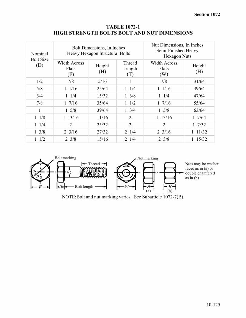
Section 1072
10-125
TABLE 1072-1HIGH STRENGTH BOLTS BOLT AND NUT DIMENSIONS
Bolt Dimensions, In InchesHeavy Hexagon Structural Bolts
Nut Dimensions, In InchesSemi-Finished Heavy
Hexagon NutsNominalBolt Size
(D) Width AcrossFlats(F)
Height(H)
ThreadLength
(T)
Width AcrossFlats(W)
Height(H)
1/2 7/8 5/16 1 7/8 31/645/8 1 1/16 25/64 1 1/4 1 1/16 39/643/4 1 1/4 15/32 1 3/8 1 1/4 47/647/8 1 7/16 35/64 1 1/2 1 7/16 55/641 1 5/8 39/64 1 3/4 1 5/8 63/64
1 1/8 1 13/16 11/16 2 1 13/16 1 7/641 1/4 2 25/32 2 2 1 7/321 3/8 2 3/16 27/32 2 1/4 2 3/16 1 11/321 1/2 2 3/8 15/16 2 1/4 2 3/8 1 15/32
NOTE:Bolt and nut marking varies. See Subarticle 1072-7(B).

Section 1072
10-126
TABLE 1072-2HIGH STRENGTH BOLTSWASHER DIMENSIONSa
Circular WashersSquare or Rectangular Beveled
Washers for AmericanStandard Beams and Channels
BoltSize
NominalOutside
NominalDiameter Thickness
MinimumSide Mean
Slope ofTaper In
D Diameter of Hole Min. Max. Dimension
Thickness Thickness
1/2 1 1/16 17/32 .097 .177 1 3/4 5/16 1:65/8 1 5/16 11/16 .122 .177 1 3/4 5/16 1:63/4 1 15/32 13/16 .122 .177 1 3/4 5/16 1:67/8 1 3/4 15/16 .136 .177 1 3/4 5/16 1:61 2 1 1/8 .136 .177 1 3/4 5/16 1:6
1 1/8 2 1/4 1 1/4 .136 .177 2 1/4 5/16 1:61 1/4 2 1/2 1 3/8 .136 .177 2 1/4 5/16 1:61 3/8 2 3/4 1 1/2 .136 .177 2 1/4 5/16 1:61 1/2 3 1 5/8 .136 .177 2 1/4 5/16 1:61 3/4 3 3/8 1 7/8 .178b .28b -- -- --
2 3-3/4 2-1/8 .178b .28b -- -- --
Over 2 to4 Incl.
2D-1/2 D+1/8 .24c .34c -- -- --
a Dimensions in inches
b 3/16 in. nominal
c 1/4 in. nominal
(F) Galvanized High Strength Bolts, Nuts, and WashersUse galvanized high strength bolts, nuts, and washers meeting all other requirementsof this subarticle except as follows:(1) Use Type 1 bolts.(2) Quench and temper washers.(3) Mechanically galvanize in accordance with the requirements of AASHTO M232
Class C.(4) Ship galvanized bolts and nuts in the same container.(5) Use organic zinc repair paint for touch-up of galvanized surfaces meeting the
requirements of Article 1080-9.(6) Include in manufacturer's test reports results of the zinc coating thickness
measurements.(7) Have each galvanized nut coated with a wax lubricant with a color contrast to that
of the zinc coating.

Section 1072
10-127
1072-8 WELDED STUD SHEAR CONNECTORSUse Type B shear studs as defined by the current edition of the ANSI/AWS/AASHTO
Bridge Welding Code D1.5.Use and install welded stud shear connectors meeting the requirements of
Article 1072-20. Ensure that shear studs and the areas of beams, girders or other structuralsteel to which the studs are welded are free of rust, rust pits, oil, grease, moisture, paint,galvanizing, loose mill scale or other deleterious matter which adversely affects the weldingoperation. Apply shear studs on steel with tightly adhering mill scale as determined by theEngineer provided acceptable results are achieved and the installed studs meet the testingrequirements of the Bridge Welding Code.1072-9 INSPECTION(A) General
Give the Materials and Tests Unit 72 hours notice for in-state producers and 192hours notice for producers out-of-state prior to beginning work in the shop. Do notmanufacture or fabricate any material, other than stock items, before the Materialsand Tests Unit is notified and the final shop drawings are reviewed, accepted andreturned to the fabricator.The contractor/fabricator shall be responsible for and shall be required to perform allquality control procedures and nondestructive testing in accordance with the BridgeWelding Code and as required by the Contract documents. Perform all qualitycontrol procedures and nondestructive testing in the presence of the Department'sinspector unless otherwise approved by the Department's inspector. Obtain approvalfor all quality control inspectors from the Department's inspector and ensure theirqualification in accordance with the Bridge Welding Code. Maintain all QualityControl Reports as required by the Bridge Welding Code, including but not limited tovisual and nondestructive testing reports and all phases of coating applicationinspection. Provide copies of all Quality Control Reports, including all radiographicfilms, to the Department inspector upon request. These copies become the propertyof the Department. No separate payment is made for this inspection and testing. Theentire cost of this work is included in the unit contract price for the structural steelitem(s) involved.Furnish facilities for the inspection of material and work in the mill and shop, andallow the inspectors free access to the necessary parts of the mill or shop. Do notship any member or component of the structural steel from the shop to the job siteprior to approval by the Department's inspector. Such approval is stamped on themember or appropriate container by the Department's inspector.Furnish the Engineer with as many copies of mill orders and shipping statements asdirected. The acceptance of any material or finished member by the Department'sinspector is not a bar to their subsequent rejection, if found defective. Replacerejected material and correct rejected work promptly and satisfactorily.
Section 1072
10-128
(B) Shop and Mill InspectionShop inspection is performed on all structural steel used on any project. Millinspection of structural steel is performed when so noted on the plans or in theSpecifications. Furnish complete certified mill test reports for all structural steelused except that a Type 6 supplier's certification as to grade of steel used isacceptable for small amounts of structural steel items which are furnished from thesupplier's stock and which are difficult to identify on any mill test report.Show in the supplier's certification the items fabricated from stock material and thepounds of steel required for each item. A supplier's certification represents onlyanchor bolts, pipe sleeves, masonry plates, sole plates, diaphragm tees, connectorplates, and web stiffener plates. Represent all other items required for a structure bycertified mill test reports as specified above.Indicate in the complete certified mill test reports the pounds of steel and the item oritems they represent and show heat number of steel, mechanical tests, chemicalanalyses, Department's project number, station number, the ASTM or AASHTOspecification to which the material conforms, and a signed statement certifying wherethe steel was melted and manufactured.Forward to the Materials and Tests Unit a letter which states by station the items andpounds of steel that are represented by a supplier's certification and those representedby certified mill test reports identifying the beam and/or plate material for each mainmember.The Department reserves the right to select any item for test. Bear any expense ofobtaining the sample. The tests are performed at the Department's expense.
(C) Sampling Structural SteelFurnish samples of structural steel at the beginning of fabrication when randomsampling is required.Furnish one sample 2 1/2" x 24" for each grade of steel used on a project. If morethan 10 heat numbers are involved in any grade of steel, 2 samples of that grade arerequired.Take all samples at the location and in the manner directed by an authorizedrepresentative of the Engineer. Furnish the necessary personnel and equipment forobtaining samples and be responsible for providing a smooth finish to the areas fromwhich the samples are taken.
(D) Charpy V-Notch TestsFurnish all structural steel for main beam and girder members (for girder memberssee plans) and for diaphragms and crossframes connecting horizontally curvedmembers meeting the longitudinal Charpy V-Notch Tests specified in thesupplementary requirements in AASHTO M270 for zone 1. Unless otherwise notedon the plans, mark and test the materials as non-fracture critical. Sample and test inaccordance with AASHTO T243 and use the (H) frequency of heat testing. Use thegrade or grades of structural steel required in the plans. Obtain and submit certified

Section 1072
10-129
mill test reports to the Materials and Tests Unit to show the results of each testrequired by this Specification.Material failing to meet the qualification requirements outlined above is unacceptablefor use on the project.
1072-10 WORKING DRAWINGSSubmit prints of checked structural steel shop drawings and changes thereto, including
shipping diagrams, for review, comments, acceptance and distribution as follows:(A) Submit 2 sets for review, comments, and acceptance on all steel structures. After
review, comments, and acceptance, submit 7 sets for distribution.(B) Submit 5 sets for review, comments, and acceptance for all bridges carrying railroad
traffic, and after acceptance submit 9 sets for distribution.(C) Furnish any additional sets requested by the Engineer or for his use, review,
comments, acceptance and/or distribution.Shop drawings are not checked by the Engineer except to ascertain general compliance
with the design and the Specifications. Thoroughly check all shop drawings in all respects.Review, comments, and acceptance of shop drawings by the Engineer is not considered asrelieving the Contractor of his responsibility for the accuracy of his drawings, or for the fitof all shop and field connections and anchors.
The maximum size of prints for shop drawings is 22" x 36", including borders which areat least 1" at the left edge of the sheet. Provide shop drawings on any medium providedthey are legible and are reproducible. Upon completion of the project, furnish to theEngineer one complete set of reproducible shop drawings that represent the as builtcondition of the structural steel including all approved changes if any. Supply drawings thatare 22" x 36". These drawings will become the property of the Department.
Changes on shop drawings after acceptance and/or distribution are subject to theapproval of the Engineer. Furnish a record of such changes.
Make substitution of sections different from those on the structure plans only whenapproved in writing.1072-11 HANDLING AND STORING MATERIALS
Load, transport, unload and store structural material so that the metal is kept clean andfree from damage. Repair any coating damage. Do not use chains, cables, or hooks thatdamage or scar the material. Repair all materials which are scarred or damaged and inspectat the fabricators expense as deemed necessary by the Engineer.
Use lifting equipment and rigging equipment with adequate capacity to handle thematerial at all times. Do not bend, twist, damage, or excessively stress any materials.Operate and maintain all lifting equipment in a safe manner and in accordance with themanufacturer's directions.
When lifting main structural steel members, the use of spreader bars is preferred. Avoidone-point pick-ups if possible. Do not use one point pick-ups on members over 50 feet in

Section 1072
10-130
length. Use two point pick-ups so that the amount of overhang and the distance betweenhooks does not exceed the distances as noted in the following table:
BEAM SIZE30" or Less 33" WF 36" WF Plate Girders
Distance Between Hooks (LF) Max
74' 80' 85' 100'
Overhang (LF) Max
25' 28' 30' 35'
Store structural material, either plain or fabricated, above the ground upon platforms,skids, or other supports, keep free from dirt, grease, vegetation, and other foreign matter,and protect as far as practicable from corrosion.
Keep material clean and properly drained. Transport and store girders and beams withthe web in the vertical plane and the top flange up. Request permission in writing and awaitapproval to invert haunched girders and beams for transport for safety reasons. Use extremecare in turn-over operations to prevent excessive bending stresses in the edge of flanges.Support long members on blocking placed near enough together to prevent damage fromdeflection.
Do not use any beam, girder, diaphragm, cross frame or other material, in any stage offabrication that will be permanently incorporated into the finished structure as a workbench,lifting device, dunnage or for any purpose for which it was not specifically intended.1072-12 STRAIGHTNESS, CAMBER, AND DIMENSIONAL TOLERANCES(A) General
Ensure that rolled material, before being laid out or fabricated, is straight. Ifstraightening is necessary, use methods that do not damage the metal. Kinks or sharpbends are cause for rejection of the material.Ensure that heat straightened or heat cambered parts are substantially free fromexternal forces, except those resulting from mechanical means used in conjunctionwith the application of heat.After heating, allow the metal to cool without artificial cooling down to 600°F.Below 600°F, only dry compressed air is permitted to artificially cool steels havingminimum yield strength greater than 36,000 psi as indicated by a mill test report.
(B) StraighteningStraighten distorted members and bent material by mechanical means or, if approved,by the carefully planned and supervised application of a limited amount of localizedheat. Do not allow the temperature of the heated area to exceed 1200°F as controlledby temperature indicating crayons or other approved methods.Following the straightening of a bend or buckle, free the surface of the metal fromevidence of fracture as indicated by visual inspection or, if directed, by appropriatenondestructive testing.

Section 1072
10-131
Shop straighten the bottom flanges of steel beams or girders at bearings as necessaryto provide uniform contact between the flanges and the bearings.
(C) CamberShow the required camber on the drawings.Make adequate provision in the fabrication of structural members to compensate forchange of camber due to welding of the shear connectors and other fabrication work.Fabricate camber into the members on built-up plate girders and trusses. Wherecamber is required on rolled sections, induce it by heat cambering, except that forrolled sections within the depth, length, and camber ordinate range shown inTable 1072-3, induce camber by cold cambering or "gagging" at the mill or in theshop provided approval procedures for cold cambering are employed.Attach cover plates on rolled sections after cambering.Where reverse curvature is required in a single rolled shape, induce it by heatcambering.Show camber diagrams showing the required offset at each tenth point of the spanand at any web splice or field splice location and blocking diagrams on the shopdrawings. Show additional points if desired by the fabricator. Ensure that the beams,girders, or other members with field splices meet all of the blocking ordinateswithout inducing stress into the members.Following cambering or camber correction, correct evidence of fracture indicated byvisual inspection or, if directed, by appropriate nondestructive testing.Show camber and blocking diagrams on the shop drawings. Shop assemblecontinuous beams meeting all the blocking ordinates without inducing stress into themembers.
TABLE 1072-3ACCEPTABLE COLD CAMBER FOR ROLLED SECTIONS
Section Designation and Nominal DepthBeam Length,
FeetW Shapes 14" to 21"
InclusiveS Shapes 12" and Over
W Shapes 24" and Over
Over 30 through 42 3/4" to 2 1/2" inclusive 1" to 2" inclusiveOver 42 through 52 1" to 3" inclusive 1" to 3" inclusiveOver 52 through 65 2" to 4" inclusive 2" to 4" inclusiveOver 65 through 85 2 1/2" to 5" inclusive 3" to 5" inclusiveOver 85 through 100 As directed by the Engineer 3" to 6" inclusive
Section 1072
10-132
(D) Heat Cambering of Rolled Beams and Welded Plate Girders(1) General
Where heat cambering is used, only Deep-Vee heating is permitted. PerformDeep-Vee heating by the carefully planned and supervised application ofa limited amount of localized heat.When minor corrections in camber are required, use small localized heatslimited to the flange material. Perform major corrections in camber by Deep-Vee heating to prevent web distortion.Begin heating at the apex of the heating pattern and progress slowly towardsthe base of the pattern as each area is brought up to temperature as stated inSubarticle 1072-12(D)(5). Do not return the heating torch toward the apex ofthe heating triangle after heating has progressed towards the base.Do not progress the heating torches toward the base of the heating patternuntil the apex of the pattern is brought up to the specified temperature.Continue heating to successive areas until the base of the triangular heatingpattern is brought up to the required temperature across the full width of theflange.
(2) Heat Cambering of Rolled BeamsHeat cambering of rolled beams is allowed to provide the required verticalcurvature. Space triangular heating patterns throughout the length of themember to provide the required curvature. Locate the apex of the heatingtriangle at a point not less than 75 percent of the depth of the membermeasured from the flange that is concave after cambering. Limit the totalincluded angle of the heating pattern to 20 degrees.Weld all detail material such as connection plates, bearing stiffeners, andgusset plates attached to the member to the rolled beam after the beam iscambered as required.
(3) Heat Cambering of Welded Plate GirdersHeat cambering of welded plate girders is only permitted when approved inwriting as a necessary repair procedure for plate girders rejected for camberdeviation.When it is necessary to correct camber deviation in welded plate girders,heating is permitted in Deep-Vee heating patterns centered on intermediatestiffeners and connection plates. Where necessary, add stiffeners for thispurpose if approved. Locate the apex of the heating pattern not less than 3/4of the depth of the member from the flange that is shortened after cooling.The maximum included angle of the heating pattern is 10 degrees. Themaximum width of the base of the heating pattern is 10". Where shallowmembers or thin webs prescribe heating patterns with a width substantiallyless than 10" at the junction of the web to flange, extend the heating pattern inthe flange at that location beyond the limits of the heating pattern in the web

Section 1072
10-133
by a maximum of 1" provided the total width of pattern in the flange does notexceed the 10" limit stated above.
(4) Support of Members for Heat CamberingHeat camber members with the web vertical and supports spaced to take themaximum advantage of dead load in the member before applying heat. Haveall supports approved by the Inspector before beginning work.Do not place any combination of support system or external load on themember that causes a compressive stress in the flange to exceed 20,000 psibefore heating for AASHTO M270 Grade 36, Grade 50 and Grade 50W steels.
(5) Heating Process and EquipmentHeat using large, approximately 1" diameter, multi-orifice (rosebud) heatingtorches operating on approximately 25 psi thermal gas and 125 psi oxygen.The torches and tips used are subject to approval. Choose torches and tips thatpromote heating efficiency and prevent unnecessary distortion.Confine heating to the patterns described herein and conduct so as to bring thesteel within the planned pattern to a temperature between 1100 and 1200° F asrapidly as possible without overheating the steel.Any heating procedure which causes a portion of the steel to exceeda temperature greater than 1,200 °F is considered destructive heating and isautomatically cause for rejection of the steel. Steel rejected for destructiveheating is investigated for re-acceptance, repair, or replacement if allowed bythe Engineer. Bear the cost of such tests and any necessary repair orreplacement.
(6) Heat MeasurementSpecified temperatures are checked using portable digital pyrometers.
(E) Heat Curving Girders(1) Type of Heating
With approval, use continuous or V-type heating methods to curve girders.For the continuous method, simultaneously heat a strip along the edge of thetop and bottom flanges that is of sufficient width and temperature to obtain therequired curvature. For V-type heating, heat the top and bottom flangessimultaneously in truncated triangular or wedge-shaped areas. Position theareas with their base along the flange edge and spaced at regular intervalsalong each flange. Set the spacing and temperatures to approximate therequired curvature by a series of short chords. Heat along the top and bottomflanges at approximately the same rate.For V-type heating, terminate the apex of the truncated triangular area appliedto the inside flange surface just before the juncture of the web and flange. Toavoid web distortion, make certain that heat is not applied directly to the webwhen heating the inside flange surfaces (the surfaces that intersect the web).

Section 1072
10-134
Extend the apex of the truncated triangular heating pattern applied to theoutside flange surface to the juncture of the flange and web. Use an includedangle of approximately 15 to 30 degrees in the truncated triangular pattern, butdo not allow the base of the triangle to exceed 10 ". Vary the patternsprescribed above only with the Engineer’s approval.For both types of heating, heat the flange edges that will be on the inside ofthe horizontal curve after cooling. Concurrently heat both inside and outsideflange surfaces for flange thickness 1¼ inches and greater. Adhere to thetemperature requirements presented below.
(2) TemperatureConduct the heat-curving operation so that the temperature of the steel neverexceeds 1150°F as measured by temperature indicating crayons or othersuitable means. Do not artificially cool the girder until it naturally cools to600°F; Use dry compressed air to artificially cool the girder.
(3) Position for HeatingHeat-curving the girder with the web in either a vertical or horizontal positionis permitted. When curved in the vertical position, brace or support the girderso that the tendency of the girder to deflect laterally during the heat-curvingprocess does not cause the girder to overturn.When curved in the horizontal position, support the girder near its ends and atintermediate points, if required, to obtain a uniform curvature. Do not allowthe bending stress in the flanges to exceed 27,000 psi. To prevent a suddensag due to plastic flange buckling when the girder is positioned horizontallyfor heating, place intermediate safety catch blocks at the midlength of thegirder within 2 inches of the flanges at all times during the heating process.
(4) Sequence of OperationsConduct the heat-curving operation either before or after completing all therequired welding of transverse intermediate stiffeners to the web. However,unless provisions are made for shrinkage, position and attach connectionplates and bearing stiffeners after heat-curving. In any event, weld thestiffeners, connection plates, and bearing stiffeners to the girder flanges afterthe member is curved. If longitudinal stiffeners are required, heat-curve oroxygen-cut these stiffeners separately prior to welding to the curved girder.
(5) CamberCamber the girders before heat-curving. Cut the web to the prescribed camberallowing for shrinkage due to cutting welding, and heat-curving. If approved,a carefully supervised application of heat is permitted to correct moderatedeviations from the specified camber.

Section 1072
10-135
(6) Measurement of Curvature and CamberHorizontal curvature and vertical camber is measured for final acceptanceafter all welding and heating operations are complete and the flanges havecooled to a uniform temperature. Horizontal curvature is checked with theweb in the vertical position by measuring offsets from a string line or wireattached to both flanges or by using other suitable means. Camber is checkedwith the web in the horizontal position. Camber the girder so that it meets thehorizontal and vertical curvature ordinates without inducing stress into thegirders by mechanical force.Compensate for loss of camber in the heat-curved girders as residual stressesdissipate during service life of the structure. This anticipated loss of camber iscomputed in accordance with the AASHTO Standard Specifications forHighway Bridges as shown on the plans.Clearly define the deviation in accordance with Subarticle 1072-12(D) fromcurvature that should be reasonably close to what AWS allows which is 1/8"per 10 foot length.
(7) Procedure Specification and Shop DrawingsSubmit structural steel shop drawings, including a detailed written procedurespecification for heat curving the girders, supplemented by calculations andsketches, for review, comments and acceptance. On the shop drawings,indicate the type, location, and spacing of heat sectors, if used, supports, andcatch blocking for each field section of girders. Also, include suitableblocking diagrams for measuring horizontal curvature similar to those usuallyprepared for camber and vertical curvature.
(F) Camber MeasurementAt the time of acceptance at the shop and after erection, ensure that all stringers andgirders for bridges meet the required camber values within the tolerances specified inSubarticle 1072-12(F). Follow the procedure for measuring camber as outlinedbelow:
(1) Assemble the member at the shop as specified in Article 1072-21 and measurewith the member lying on its side.
(2) Camber repairs are only allowed when approved by the Engineer. Camberdeviation is judged irreparable if corrective measures in the shop produce webbuckling in excess of the specified tolerance, in which case the member isrejected.
(3) The final camber measurement is made by the Engineer in the field aftererection. At the time of this measurement, ensure that the members have all ofthe specified camber less the dead load deflection of the steel as specified inSubarticle 1072-12(F).

Section 1074
10-136
(G) Dimensional TolerancesEnsure that dimensions of all material covered by Section 1072 conform toASTM A6 when received at the fabrication shop. Fabricate member dimensionsconforming to this subarticle whether designated to be straight, cambered, or curvedand regardless of whether curvature is heat-induced (when so permitted).Dimensional tolerances not listed in this subarticle shall be as specified by the BridgeWelding Code as defined in Article 1072-20 and apply to rolled shapes whereapplicable as well as to welded members.Place welded butt joints no further than 1/2" from the point detailed. Intermediatestiffeners varying ±1/2" maximum from the point detailed are allowed. Connectorplates for field connections varying ±1/8" from the point detailed are allowed.Ensure that the actual centerline of bearing lies within the thickness of the bearingstiffener.Members with end milled for bearing and members with faced end connection anglesdeviating from the detailed length by -0, +1/32" maximums are acceptable. All othermembers varying from detailed length by ±1/8" maximum are acceptable.
Align to within ±1/8" from the location shown on the approved shop drawings allsteel requiring shop assembly for reaming, drilling from the solid or weld jointpreparation.Deviation from specified camber of fabricated members prior to shipment from thefabrication shop is limited to:-0;+3/32" x No. of ft. from nearest bearing up to 3/4" maximum
10Deviation from specified camber of erected steel bridge superstructures measuredwhen the steel work is complete and the superstructure is subject to steel dead loadstresses only is limited to:-0;+1/8" X No. of ft from nearest bearing up to 1" maximum 10If the plans do not require shop induced camber, provide an actual member that isstraight or one of the following:(1) If natural camber "turned up" is required, the maximum plus camber is the
algebraic sum of the allowable deviation, dead load deflection, vertical curveordinate, and superelevation ordinate;
(2) If natural camber 'turned down" is required, the maximum negative camber isequal to the algebraic sum of the dead load deflection, vertical curve ordinate,and superelevation ordinate.

Section 1074
10-137
1072-13 OXYGEN CUTTINGOxygen cutting of structural steel is allowed, provided a smooth surface free from cracks
and notches is secured and an accurate profile is secured by the use of a mechanical guide.Hand cut only where approved and grind smooth leaving no burnt edges.
In all oxygen cutting, adjust and manipulate the cutting agent to avoid cutting beyond(inside) the prescribed lines. Provide oxygen cut surfaces meeting the ANSI surfaceroughness rating value of 1,000 except ensure that oxygen cut surfaces of members notsubject to calculated stress meet the surface roughness value of 2,000. Round corners ofoxygen cut surfaces of members carrying calculated stress to a 1/16" radius, or an equivalentflat surface at a suitable angle, by grinding after oxygen cutting.
Fillet re-entrant cuts to a radius of not less than 1".Remove surface roughness exceeding the above values and occasional notches, gouges,
and cracks not more than 1/16" deep on otherwise satisfactory oxygen cut surfaces bychipping or grinding. Flair corrections of the defects with the surface of the cut on a bevelof 1 to 6 or flatter.
Repair occasional gouges of oxygen cut edges more than 3/16" deep but not more than7/16" deep by welding with low hydrogen electrodes not exceeding 5/32" in diameter andwith a minimum preheat of 250°F. Grind the completed weld smooth and flush with theadjacent surface. Radiographically test any gouge over 1/8" deep after the repair.1072-14 EDGE PLANING
Plane sheared edges of plates more than 5/8" in thickness that carry calculated stress to adepth of 1/4". Fillet re-entrant cuts before cutting. Round all edges of plates and shapesparallel to calculated stress and all free edges of plates and shapes intended for coating orgalvanizing to 1/16" radius or provide an equivalent flat surface at a suitable angle. Grindedges of all other plates and shapes to remove burrs, slag, or shear lip. The ends of all steelpiles, intended for coating or galvanizing, are not required to be radiused, but remove allburrs, slag, and shear lip.1072-15 FACING OR BEARING SURFACES
Provide a surface finish of bearing and base plates and other bearing surfaces that comein contact with each other or with concrete that meet the following ANSI surface roughnessrequirements as defined in ANSI B46.1, Surface Roughness, Waviness, and Lay, Part I:Steel slabs ..........................................................................................................ANSI 2,000Heavy plates in contact in shoes to be welded ..................................................ANSI 1,000Milled ends of compression members, milled or
ground ends of stiffeners and fillers ................................................................ANSI 500Bridge rollers and rockers .....................................................................................ANSI 250Pins and pin holes .................................................................................................ANSI 125Sliding bearings ....................................................................................................ANSI 125

Section 1074
10-138
1072-16 ABUTTING JOINTSFace and bring to an even bearing abutting joints in compression members and girder
flanges, and in tension members where so indicated on the drawings. Where joints are notfaced, do not exceed an opening of 1/4".1072-17 BENT PLATES
Provide cold-bent, load carrying rolled-steel plates conforming to the following:(A) Take from the stock plates so that the bendline is at right angles to the
direction of rolling.(B) Use a radius of bends such that no cracking of the plate occurs. Use minimum
bend radii, measured to the concave face of the metal, as shown in Table 1072-4.If a shorter radius is essential, bend the plates hot at a temperature not greater than1200°F and air cool slowly down to a temperature of 600°F. Below 600°F only drycompressed air is permitted to artificially cool steels having a minimum yieldstrength greater than 36,000 psi. Use hot bent plates conforming to requirement 1above.(C) Before bending, round the corners of the plates to a radius of 1/16" throughout the
portion of the plate at which bending occurs.TABLE 1072-4
MINIMUM BEND RADII
Plate Thickness(t), Inches
Minimum Bend Radii,Ratio of Thickness
Up to 1/2 2tOver 1/2 to 1 2 1/2t
Over 1 to 1 1/2 3tOver 1 1/2 to 2 1/2 3 1/2t
Over 2 1/2 to 4 4tNOTE: Hot bend low alloy steel in thicknesses over 1/2" for small radii, if
required.1072-18 HOLES FOR BOLTS AND OTHER FASTENERS(A) General
Punch or drill all holes and remove any burrs. Punching material forming parts ofa member composed of not more than 5 thickness of metal 1/16" larger than thenominal diameter of the fastener is allowed whenever the thickness of the material isnot greater than 3/4" for structural steel, 5/8" for high-strength steel, or 1/2" forquenched and tempered alloy steel, unless subpunching and reaming is required bySubarticle 1072-18(D).When there are more than 5 thicknesses or when any of the main material is thickerthan 3/4" for structural steel, 5/8" for high-strength steel, or 1/2" for quenched andtempered alloy steel, either subdrill and ream or drill all holes full size.

Section 1074
10-139
When required by Subarticle 1072-18(D), subpunch or subdrill all holes (subdrill ifthickness limitation governs) 1/4" smaller and, after assembling, ream 1/16" larger ordrill full size to 1/16" larger than the nominal diameter of the fastener.
(B) Punched HolesDo not use a diameter of the die exceeding the diameter of the punch by more than1/16". If any holes require enlargement to admit the fasteners, ream such holes.Clean cut holes without torn or ragged edges. Poor matching of holes is cause forrejection. Grind all burrs smooth.
(C) Reamed or Drilled HolesMake reamed or drilled holes cylindrical, perpendicular to the member, andcomplying with the size requirements of Subarticle 1072-18(A). Where practicable,direct reamers by mechanical means. Grind all burrs smooth. Poor matching ofholes is cause for rejection. Ream and drill with twist drills. If required, takeassembled parts apart for removal of burrs caused by drilling. Assemble connectingparts requiring reamed or drilled holes, securely hold while reaming or drilling andmatch mark before disassembling.
(D) Subpunching and Reaming of Field ConnectionsSubpunch or subdrill, if required according to Subarticle 1072-18(A), holes in allfield connections and field splices of main members of trusses, arches, continuousbeam spans, bents, towers (each face), plate girders, and rigid frames. Subsequentlyream while assembled as required by Article 1072-21. Subpunch and ream to a steeltemplate or ream while assembled all holes for floor beam and stringer field endconnections. Ream or drill full size field connection holes through a steel templateafter the template is located with utmost care as to position and angle and firmlybolted in place. Use templates for reaming matching members, or the opposite facesof a single member that are exact duplicates. Accurately locate templates used forconnections on like parts of members such that the parts or members are duplicatesand require no match-marking.
(E) Accuracy of Punched and Subdrilled HolesAccurately punch or subdrill all holes punched full size, subpunched, or subdrilledsuch that after assembling (before any reaming is done) a cylindrical pin 1/8" smallerin diameter than the nominal size of the hole enters perpendicular to the face of themember, without drifting, in at least 75 percent of the contiguous holes in the sameplane. If the requirement is not fulfilled, the badly punched pieces are rejected. Ifany hole does not pass a pin 3/16" smaller in diameter than the nominal size of thehole, this is cause for rejection.
(F) Accuracy of Reamed and Drilled HolesWhen holes are reamed or drilled, ensure that 85 percent of the holes in anycontiguous group, after reaming or drilling, show no offset greater than 1/32"between adjacent thicknesses of metal.

Section 1074
10-140
Use all steel templates with hardened steel bushings in holes accurately dimensionedfrom the centerlines of the connection as inscribed on the template. Use thecenterlines in locating accurately by the template from the milled or scribed ends ofthe members.
(G) Alternate MethodsAs an option, make the fastener holes by procedures other than those described inSubarticles 1072-18(A) through 1072-18(F) provided that the requirements forquality and for dimensional accuracy are met. Wherever an alternate method isemployed, demonstrate the ability of each alternate method to produce holes andconnections consistently meeting all requirements for quality and dimensionalaccuracy for the type of joint fabricated. When such ability of an alternate method ispreviously demonstrated on similar work for the Department, continue its use bycertifying, on each subsequent project, that the procedure and equipment are the sameas the method previously qualified, and that the equipment involved is in good repairand adjustment. Failure of joints to meet the quality and accuracy requirements iscause for rejection. In the case of repeated failures revise and/or requalify themethod or discontinue its use.At the time of qualification of an alternate method, submit for approval a writtenprocedure specification describing the procedures and equipment and giving upperand lower value limits and tolerances for all pertinent variables. Accurately reflectthe actual procedures, equipment, and values used in the qualification tests. Inaddition to the certification on each subsequent project, the Engineer occasionallyrequests copies of the approved procedure specification.
(H) Oversize, Short-Slotted, and Long-Slotted HolesWhere shown on the plans or permitted in writing, use oversize, short-slotted, andlong-slotted holes with high strength bolts 5/8" and larger in diameter. Do not allowthe distance between edges of adjacent holes or edges of holes and edges of membersto be less than permitted under the AASHTO specification. Oversize, short-slotted,and long-slotted holes are defined as follows:(1) Oversize holes are 3/16" larger than bolts 7/8" and less in diameter, 1/4" larger
than bolts 1" in diameter, and 5/16" larger than bolts 1 1/8" and greater indiameter. When oversized holes are permitted, they are allowed in any or allplies of friction type connections. Install hardened washers over exposedoversize holes.
(2) Short-slotted holes are 1/16" wider than the bolt diameter and have a length thatdoes not exceed the oversize diameter requirements of Sub-paragraph 1 bymore than 1/16". When short-slotted holes are permitted, they are allowed inany or all plies of friction-type or bearing-type connection. Locate holeswithout regard to direction of loading in friction-type connections, but orientnormal to the direction of the load in bearing-type connections. Installhardened washers over exposed short-slotted holes.

Section 1074
10-141
(3) Long-slotted holes are 1/16" wider than the bolt diameter and have a lengthmore than allowed in Sub-paragraph 2 but not more than 2 1/2 times the boltdiameter. Structural plate washers or a continuous bar not less than 5/16" inthickness are required to cover long slots that are the outer plies of joints.Ensure that these washers have a size sufficient to completely cover the slotafter installation. When long-slotted holes are permitted, they are allowed inonly one of the connected parts of either a friction-type or bearing-typeconnection at an individual faying surface.When used in friction-type connections, locate holes without regard todirection of loading if one-third more bolts are provided than needed to satisfythe allowable unit stresses except as herein restricted.When used in bearing-type connections, orient the long diameter of the slotnormal to the direction of loading. No increase in the number of bolts overthose necessary for the allowable unit stress is required.
(I) MisfitsWhen misfits occur for any reason, enlargement of the holes by reaming is limited to1/16" over the nominal size hole called for unless otherwise permitted in writing.
(J) Erection Bolt HolesAt field welded connections where erection bolts are used, provide holes 3/16" largerthan the nominal erection bolt diameter.
1072-19 INSTALLING BOLTSInstall high strength bolts in accordance with the requirements of Article 440-10.
1072-20 WELDING(A) Definition
The Bridge Welding Code referred to herein is the edition of theANSI/AWS/AASHTO Bridge Welding Code D-1.5 and any applicable interim that iscurrent on the date of advertisement for the project, and as modified by thespecifications.
(B) GeneralWeld all structural steel in the shop or in the field for bridges, whether permanent ortemporary, and perform all other work related to structural welding including, but notlimited to, testing and inspection of welds, preparation of material, oxygen cutting,electrodes, shielding, and shear studs, meeting the requirements of the BridgeWelding Code. Weld other steel items in accordance with the requirements of theapplicable AWS Welding Code.Weld only where shown on the plans or where called for in the Specifications unlessrequesting and receiving written approval for additional welding.Show all permanent and all temporary welds on the shop drawings. For groovewelds, indicate on the shop drawings the particular detail and process to be employed

Section 1074
10-142
in production of the work. For prequalified joints, use of the Bridge Welding Codeletter classification designation of the joint (B-L2b-S etc.) along with the appropriatesymbol satisfies this requirement. Tack welds that become part of a permanent weldare not required on the shop drawings.Provide fillet welds, including seal welds, at least the minimum size allowed by theBridge Welding Code for the thickness of material welded or the size called for onthe plans, whichever is larger. For exposed, bare, unpainted applications of steel, thebasic requirements for weld filler metal with atmospheric corrosion resistance andcoloring characteristics similar to that of the base metal are mandatory. Thevariations from these basic requirements listed in the Bridge Welding Code for singlepass welds are not permitted.Use only Department approved electrodes for welding. The Department maintains alist of approved brands of electrodes for which satisfactory reports of tests madewithin one year are previously submitted. This list is available from the StateMaterials Engineer. Designate an appropriate storage area for all weldingconsumables that meets all requirements of the Bridge Welding Code.
(C) Qualification of PersonnelEnsure that each welder, welding operator and tacker is qualified in accordance withthe Bridge Welding Code or other applicable AWS Welding Code as determined bythe Engineer. Employ welders that are qualified by the Department. Welders shallbe requalified by the Department every five years. Contact the Materials and TestsUnit to schedule qualification tests. Permanent in-shop welders employed by afabricator who passed the appropriate welding tests and whose weldments areradiographically tested with acceptable results on a regular basis are exempt fromadditional testing when approved by the Engineer. Have a representative of thetesting agency witness all phases of the qualification tests including preparation ofthe test plates and placing of welds. As evidence of such qualification, furnish asatisfactory certificate, or a copy thereof, issued by a testing agency which isapproved by the Engineer, for each welder, welder operator, and tacker employed onthe work. Submit certification for each welder, welding operator, or tacker, and foreach project, stating the name and Social Security number of the welder, weldingoperator, or tacker; the name and title of the person who conducted the examination;the kind of specimens; the position of welds; the American Welding Societyelectrode classification used; the results of the tests; and the date of the examination.Such certifications are required for all persons performing shop or field welds of anykind on the work, whether permanent or temporary. Have each welder provide apicture ID upon request or other form of positive identification as required by theEngineer.
(D) Qualification of Welds and ProceduresUse welds, except as otherwise provided below, that are prequalified in accordancewith the details, limitations, and procedures prescribed by the Bridge Welding Codeor other AWS Welding Code as determined by the Engineer. Substitute other suchprequalified welds for those shown on the plans, subject to the approval of the

Section 1074
10-143
Engineer. Use welds departing from those prequalified only if submitting to theEngineer details of the proposed joints and joint welding procedure Specification forapproval, and at no cost to the Department demonstrate their adequacy in accordancewith the requirements of the Bridge Welding Code.Include in procedure specifications, upper and lower value limits of all variableslisted for procedure qualification in the Bridge Welding Code for the process orprocesses used. Written welding procedure specifications are required forprequalified welds also.On all welding, include in the welding procedure continuous visual inspection bywelders, welding operator, tackers, welding supervisors, and all personnel involvedin preparation of the material for welding.Approval by the Engineer of the procedure specifications does not relieve theContractor of his responsibility to develop a welding procedure that producesweldments meeting the required quality and dimensions.If non-prequalified joints procedures are previously found acceptable to the Engineeron another project, furnish the inspector with a copy of the joint details andprocedure specification approved at the time of qualification. Such documentation isrequired from each fabricator employing a non-prequalified joint or procedure on thework. Failure to produce such documentation results in the fabricator being requiredto requalify the joint or procedure, or to use prequalified joints, procedures, andprocedure specifications.On weldments where geometric shape prevents compliance with requirements toweld a particular position, alternate procedures are considered for approval.Previously qualified alternate procedures are considered for approval without furtherprocedure qualification tests. No separate payment is made for developing,demonstrating, and documenting for future use such alternate procedures, as suchwork is considered incidental to the work of welding.
(E) Requirements for Testing and InspectionRequire the fabricator to make provisions for convenient access to the work forinspection and cooperate with the inspector during the required inspection andtesting.Inspect welds in the presence of the Department's inspector unless otherwiseapproved by the Department's inspector, using visual inspection and thenondestructive tests herein prescribed in addition to the test requirements of theBridge Welding Code and the contract documents. Employ quality control inspectorsand NDT technicians qualified in accordance with the Bridge Welding Code andpreapproved by the Engineer prior to the start of any fabrication. Supply theappropriate certifications as required by the Bridge Welding Code to theDepartment's inspector for all inspectors. Individuals assigned to production weldingactivities or processes and their supervisors are not acceptable for performing qualitycontrol testing. Have a qualified welding inspector present any time welding is inprogress. No separate payment is made for inspection and testing. The entire cost of

Section 1074
10-144
this work is included in the unit contract price for the structural steel item(s)involved.Retest welds requiring repairs or replacement in the presence of the Department'sinspector after the repairs or replacements are made.If the Engineer finds that acceptable repair to defective work is not feasible; theentire piece is rejected.Payment at the contract prices for the various items in the contract which include thework of welding is full compensation for all costs resulting from the requirednondestructive testing of welds and from the required inspection of welds.
(F) Nondestructive Test RequiredThe extent of nondestructive testing required is as prescribed in the Bridge WeldingCode and by the contract documents except radiograph all flange splices for their fulllength. The term "main members" in this regard means girders, beams, floor beams,stringers, truss members, high strength bolts, columns, bearing stiffeners, bearingshoes, high mount lighting standards, and components of main member carryingstress, including the end connections for such members. Nondestructive testing ofother complete welds or weld passes is required when so noted on the plans ordeemed necessary by the Engineer. Tests other than those prescribed are alsorequired when deemed necessary by the Engineer. Perform all radiographic testingin accordance with procedures established by the Engineer. Copies of theseprocedures are available from the State Materials Engineer.Use edge blocks when radiographing butt welds greater than 1/2" in thickness. Useedge blocks with a length sufficient to extend beyond each side of the weld centerlinefor a minimum distance equal to the weld thickness, but not less than 2" and witha thickness equal to or greater than the thickness of the weld. Use edge blocks witha minimum width equal to half the weld thickness, but not less than 1”. Center theedge blocks on the weld with a snug fit against the plate being radiographed allowingno more than 1/16" gap. Produce edge blocks from radiographically clean steel andprovide a surface finish of ANSI 125 or smoother.High mount lighting standards longitudinal groove welds and fillet welds areradiographically tested as specified by the contract drawings. Other nondestructivetest methods are sometimes deemed necessary by the Engineer to determine thequality of the welds. No separate payment is made for inspection and testing. Theentire cost of this work is included in the unit contract price involved.
(G) Welded Structural ShapesProduce butt welds of flanges and webs, and fillet welds of web to flanges of plategirders and haunched beams using the submerged arc process. Produce otherstructural shapes built up from plates and bars using the submerged arc processunless another process is qualified for these joints in accordance with the BridgeWelding Code and is subject to the approval of the Engineer.

Section 1074
10-145
After all shop welded splices in the flanges and webs for the full length of the fieldsection are made, tested, and approved, fit the flange plates tight and square againstthe web so as to leave no gap and to not bow the web. Brace one side of each flangeagainst the web with gussets or struts and tack weld securely to the web at thestiffener locations. Upon removal of the welds, grind any nicks or gouges, preheat,weld and test or incorporate into the stiffener fillet weld.Connect the flanges to the web by starting the fillet weld at one end of the girder andproceeding to the other ends.As an option, make adjacent welds simultaneously.The sequence for making the flange to web fillet welds is subject only to theprovisions for control of shrinkage and distortion and to the position requirements ofthe Bridge Welding Code.After flange to web welds are complete, shift bracing gussets or struts if necessary,then remove all temporary gussets or struts. Remove tack welds by grinding flushwith parent metal.Straighten any transverse warpage of the flanges if necessary by heating along thecenterline of the outside face.Fit tight, square, and tack weld stiffeners securely to the web. With the girder in theflat position (web horizontal), weld the stiffeners to the web. Do not weld or tackweld stiffeners to the flanges except where noted on the plans.After all parts are welded into place, trim the girder to detail length with adjustmentsfor slope and end rotation exceeding 1/4" net.
1072-21 SHOP ASSEMBLING(A) General:
Assemble the field connections of main members of continuous beam spans, plategirders, and rigid frames in the shop with milled ends of compressing members infull bearing, and then ream their sub-size holes to specified size while theconnections are assembled. Assembly shall be either Full Girder Assembly orProgressive Girder Assembly unless Full Girder Assembly or Special CompleteStructure Assembly is required by the contract.Furnish a camber diagram to the Engineer showing the camber at each panel point ofeach continuous beam line, plate girder, or rigid frame. When the shop assembly isFull Girder Assembly or Special Complete Structure Assembly, have the camberdiagram show the camber measured in assembly. When any of the other methods ofshop assembly is used, show the calculated camber in the camber design.Clean surfaces of metal in contact before assembling. Assemble the parts ofa member, pin well, and firmly draw together with bolts before reaming. Takeassembled pieces apart, if necessary, for removal of burrs and shavings produced bythe reaming operation. Ensure that the member is free from twists, bends, and otherdeformation.

Section 1074
10-146
Drift during assembling only to bring the parts into position, and not sufficient toenlarge the holes or distort the metal. If any holes are enlarged to admit the fasteners,ream them.Match-mark those connecting parts assembled in the shop for the purpose of reamingholes in field connections and provide a diagram showing marks furnished by theEngineer.
(B) Full Girder AssemblyFull Girder Assembly consists of assembling all members of each continuous beamline, plate girder, or rigid frame at one time.
(C) Progressive Girder AssemblyProgressive Girder Assembly consists of assembling initially for each continuousbeam line or plate girder at least 2 contiguous shop sections or all members in at least2 contiguous shop panels but not less than the number of panels associated with threecontiguous section lengths (i.e., length between field splices) and not less than150 feet in the case of structures longer than 150 feet. Add at least 1 shop section atthe advancing end of the assembly before removing any member from the rearwardend, so that the assembled portion of the structure is never less than the specifiedabove.
(D) Special Complete Structure AssemblySpecial Complete Structure Assembly consists of assembling the entire structure,including the floor system.Have each assembly, including camber, alignment, accuracy of holes, and fit ofmilled joints, approved by the Engineer before reaming.
1072-22 PAINTING AND OTHER PROTECTIVE COATINGSShop paint in accordance with the requirements of Section 442.Repair galvanized surfaces that are abraded or damaged in accordance with
Article 1076-6.1072-23 MARKING AND SHIPPING
Paint or mark each member with an erection mark for identification and furnish anerection diagram with erection marks shown thereon.
Furnish to the Engineer as many copies of material orders, shipping statements, anderection diagrams as the Engineer directs. Show the weights of the individual members onthe statement. Mark the weights on members weighing more than 3 tons. Load structuralmembers on trucks or cars in such a manner that they are transported, unloaded, and storedat their destination without being excessively stressed, deformed, or otherwise damaged.
Structural members shall be loaded on trucks or cars in such as manner that they may betransported to their destination without being excessively stressed, deformed or otherwisedamaged.
Section 1074
10-147
Restrain overhanging ends of beams or girders both vertically and horizontally toprevent excess movement. Chains are permitted to secure beams and girders duringshipping only when adequate measures are taken to prevent damage to the material by theuse of approved protective material. If necessary, use adequate bracing to prevent bendingof the top flange.
Pack bolts of one length and diameter and loose nuts or washers of each size separately.Ship pins, small parts, and packages of bolts, washers, and nuts in boxes, crates, kegs, orbarrels, but do not allow the gross weight of any package to exceed 300 lbs. Plainly marka list and description of the contained material on the outside of each shipping container.
Steel die stamped heat numbers, fabricator's identity, station number, girder number andspan number of main members into an unpainted area (if available) near the end of themember. Die stamp members with painted ends outside the painted area but as close to theend as possible.
Steel die stamp the heat numbers of all major components of main members in the nearend, near side of each girder in such a manner that the heat number is referenced to theappropriate component. Paint the heat number on the painted surface of the member alongwith the erection marks.
Ship anchor bolts, washers, and other anchorage or grillage materials, in time to beincorporated into the masonry portion of the structure.
SECTION 1074MISCELLANEOUS METALS AND HARDWARE
1074-1 WELDINGCertify all welders performing any welding on any metals in accordance with the
applicable AWS welding code in the position and process required as approved by theEngineer.1074-2 EXPANSION ANCHORS
Unless otherwise shown on the plans, provide expansion anchors consisting of 2 or moreunits with a minimum of 2 hard metal conical ring wedges and 2 expandable lead sleeves ofan equally effective design that is approved by the Engineer. Use anchors providinga minimum safe holding power of 3,000 pounds for 3/4" bolts and 2,000 pounds for5/8" bolts, based upon 1/4 of the actual holding power of the anchor in 3,000 psi concrete.Furnish satisfactory evidence, based upon actual tests performed by a commercial testinglaboratory, which indicate that the anchors develop the minimum required safe holdingpower.
When it is proposed to use anchors that are previously accepted as meeting the aboverequirements, the anchors are accepted on the basis of a certified statement indicating theprior acceptance of the furnished anchors.1074-3 PLAIN STEEL BARS WITH THREADED ENDS
Provide plain steel bars with threaded ends meeting the requirements ofAASHTO M183.

Section 1074
10-148
1074-4 HARDWARE FOR TIMBER STRUCTURESUse machine bolts, drift-bolts, and dowels that are either wrought iron or medium steel.
Use washers that are cast iron ogee, malleable iron castings, or cut from medium steel orwrought iron plate.
Use machine bolts with square heads and nuts. Use nails that are cut or round wire ofstandard form. Use spikes that are cut, wire spikes, or boat spikes.
Use black or galvanized nails, spikes, bolts, dowels, washers, and lag screws foruntreated timber.
Galvanize or cadmium plate all hardware for treated timber bridges, except malleableiron connectors.1074-5 METAL BRIDGE RAILING(A) General
As an option, use either aluminum or galvanized steel metal rail, provided that thesame material is used on all structures on the project.Certified mill test reports are required for rails and posts.Place a permanent identifying mark that identifies the fabricator on each post. Usea method and location of the identifying mark such that it does not detract from theappearance of the post.Where it is necessary for rails to be curved, form the curvature in the shop or in thefield. Uniformly curve the rail without buckling or kinking. Perform all welding inaccordance with AWS D1.1 for steel railing and AWS D1.2 for aluminum railing.Provide an anchor unit of sufficient strength to insure load anchoring capacity asspecified for rail loading in the AASHTO Standard Specifications for HighwayBridges.
(B) Aluminum RailSupply material for posts, post bases, rails, expansion bars, and clamp bars meetingthe requirements of ASTM B221 for alloy 6061-T6.Use material for rivets meeting the requirements of ASTM B316 for alloy 6061-T6.Use rivets that are standard button head and cone point cold driven.Use material for nuts meeting the requirements of ASTM B211 for alloy 6061-T6.Provide material for washers meeting the requirements of ASTM B209 for alloyalclad 2024-T3.Supply material for shims meeting the requirements of ASTM B209 foralloy 6061-T6.Ensure that the handrails meet the dimensional tolerance requirements ofANSI H35.2.

Section 1074
10-149
(C) Galvanized Steel RailUse posts, post bases, rails, expansion bars, and clamp bars meeting the requirementsof AASHTO M183 and galvanize in accordance with AASHTO M111. Grind the cutends of rail smooth and give them 2 coats of organic zinc repair paint. Galvanize theposts and post bases after they are riveted together.Use rivets meeting the requirements of ASTM A502 for Grade 1 rivets.Use bolts meeting the requirements of ASTM F593 alloy 304.Use nuts meeting the requirements of ASTM F594 alloy 304.Use washers meeting the requirements of ASTM F844 except made from alloy 304stainless steel.Use materials for shims meeting the requirements of ASTM A570 for Grades 36, 40,or 45, or A611 for Grade C, and galvanized in accordance with AASHTO M111.
1074-6 STEEL PIPESteel pipe bent or welded in fabricating shall meet the requirements of ASTM A53 for
standard weight pipe. Use galvanized pipe unless otherwise shown on the plans.1074-7 IRON CASTINGS(A) General
Boldly fillet castings at angles, and provide arrises that are sharp and perfect. Nosharp, unfilleted angles or corners are permitted. Provide castings that are true topattern in form and dimensions, free from pouring faults, sponginess, cracks, blowholes, and other defects affecting their strength and value for the service intended.Sand blast or otherwise effectively clean of scale and sand all castings to presenta smooth, clean, and uniform surface. Welding is not allowed for the purpose ofmaking a casting structurally sound. Welding for cosmetic or other purposes is notallowed without approval of the Engineer.
(B) Gray Iron CastingsSupply gray iron castings meeting the requirements of AASHTO M306. Proof loadtesting will only be required for new casting designs during the design process.Acceptance of production castings will be based on test bars. Cast test bars, of size“B”, attached to and integral with the castings. In lieu of this, cast test bars separatefrom the castings when approved in writing by the Engineer. The Engineer reservesthe right to require that a test bar be machined from an actual casting if deemednecessary. Unless otherwise specified, do not coat gray iron castings. Do notperform any welding on castings for any reason without prior approval from theEngineer. Mark castings with the NCDOT Standard Number of the casting design.
1074-8 STEPSFabricate steps for minor drainage structures from deformed reinforcing bars, use gray
iron castings meeting the requirements of Subarticle 1074-7(B), or use composite plastic-steel construction as shown on the plans.

Section 1074
10-150
The use of steps differing in dimension, configuration, or materials from those shown onthe plans is allowed by furnishing the Engineer with details of the proposed steps andobtaining written approval for the use of such steps.1074-9 FABRICATED STEEL GRATES
Use fabricated steel grates made from bars that meet the requirements ofAASHTO M183. Galvanize the grates after fabrication in accordance withAASHTO M111.1074-10 PINS
Supply pins for bearing assemblies meeting the requirements of either AASHTO M183or AASHTO M169 for grades 1016 through 1030, unless otherwise required by the plans orspecifications.1074-11 WASHERS
Provide washers for use with fasteners meeting the requirements of AASHTO M293M.Provide washers for high strength bolts meeting the requirements of Article 1072-7.
Ensure that the size and finish (plain, weathering, or galvanized) of washers iscompatible with the fastener.1074-12 METAL STAY-IN-PLACE FORMS
Provide metal stay-in-place forms for concrete floor slabs of zinc-coated (galvanized)steel sheet conforming to ASTM specification A653 (Structural Steel (SS) Grade 33 through80) with coating class of G165 meeting all requirements relevant to steel stay-in-place formsas noted on the contract plans. Do not use material thinner than 20 gage.
SECTION 1076GALVANIZING
1076-1 GALVANIZINGWherever galvanizing is required, perform the galvanizing in accordance with this
section of the Specifications except where other requirements for galvanizing are includedin other sections of the specifications.1076-2 FABRICATED PRODUCTS
Galvanize products fabricated from rolled, pressed, and forged steel shapes, plates, bars,and strips, 1/8" thick and heavier in accordance with AASHTO M111. Fabricate productsinto the largest unit that is practicable to galvanize before the galvanizing is done.Fabrication includes all operations necessary to complete the unit such as shearing, cutting,punching, forming, drilling, milling, bending, welding, and riveting. Galvanize componentsof bolted or riveted assemblies separately before assembly. When it is necessary tostraighten any sections after galvanizing, perform such work without damage to the zinccoating.
Completely seal all edges of tightly contacting surfaces by welding before galvanizing.

Section 1076
10-151
Commercial blast clean components with partial surface finishes in accordance withSubarticle 442-8(A) prior to pickling.1076-3 HARDWARE
Galvanize iron and steel hardware in accordance with AASHTO M232.1076-4 ASSEMBLED PRODUCTS
Galvanize assembled steel products in accordance with AASHTO M111.Completely seal all edges of tightly contacting surfaces by welding before galvanizing.
1076-5 SHEETSGalvanize iron or steel sheets in accordance with ASTM A653.
1076-6 REPAIR OF GALVANIZINGRepair galvanized surfaces that are abraded or damaged at any time after the application
of zinc coating by thoroughly wire brushing the damaged areas and removing all loose andcracked coating, after which paint the cleaned areas with 2 coats of organic zinc repair paintmeeting the requirements of Article 1080-9. Ensure that the total thickness of the 2 coats isnot less than 3 dry mils. In lieu of repairing by painting with organic zinc repair paint, othermethods of repairing galvanized surfaces that are abraded or damaged are allowed providedthe proposed method is acceptable to the Engineer.
Excessive damage to galvanized surfaces as determined by the Engineer is cause forrejection. Replace or re-galvanize rejected galvanized material.
SECTION 1077PRECAST CONCRETE UNITS
1077-1 GENERALUse precast concrete units from sources participating in the Department's Precast
Concrete Quality Control/Quality Assurance Program. A list of participating sources isavailable from the Materials and Tests Unit's Central Laboratory. The Department willremove a manufacturer of precast concrete units from this program in the event that themonitoring efforts indicated that non-specification material is being provided or testprocedures are not being followed.
This section covers the materials for and the production of precast reinforced concreteunits produced in accordance with the contract.
Where precast reinforced concrete circular manhole sections are used, they shall meetthe requirements of AASHTO M199 in addition to the requirements of this section.1077-2 PLAN REQUIREMENTS
The plans for precast units will be standard drawings or details shown in the projectplans, furnished by the Department.
When the Department does not make precast plans available and the Contractor choosesto precast, submit drawings to the Engineer for the items proposed to precast. Submit one

Section 1077
10-152
complete set of drawings for review, at least 40 calendar days prior to precasting. Afteracceptance, submit 7 complete sets of drawings. Acceptance by the Engineer of contractordrawings will not be considered as relieving the Contractor of any responsibility for precastunits. When precast units are load bearing and require structure design, have the plansprepared and certified by a North Carolina Registered Professional Engineer. Contractorfurnished drawings shall show complete design, installation, and construction information insuch detail as to enable the Engineer to determine the adequacy of the proposed units for theintended use. Contractor drawings shall also include details of steel reinforcement size andplacement and a schedule that lists the size and type of precast units at each location wherethe precast units are to be used. Produce precast units in accordance with the approveddrawings.1077-3 MATERIALS
All materials shall meet the requirements of Division 10 shown below:Item SectionCoarse Aggregate 1014-2Fine Aggregate 1014-1Portland Cement 1024-1Type IP Blended Cement 1024-1Fly Ash 1024-5Water 1024-4Type IS Blended Cement 1024-1Ground Granulated Blast Furnace Slag 1024-6Silica Fume 1024-7Air Entraining Agent 1024-3Chemical Admixtures 1024-3Reinforcing Steel 1070Miscellaneous Metals 1074Curing Agents 1026
1077-4 INSPECTIONThe Department reserves the right to place a duly authorized inspector in the plant at any
time work related to the production of units for the Department is being performed. Notifythe Engineer at least 7 days in advance when such work is scheduled to begin.
Provide an office area for the inspector of at least 50 square foot with desk, chair,telephone, facilities for proper heating and cooling, adequate lightning and electrical outlets.
Acceptance of precast units will be on the basis of tests of materials, compression testson concrete cylinders, and inspection of the finished units, including amount and placementof steel reinforcement, to determine their conformance with the approved dimensions anddesign and their freedom from defect. The inspector will have the authority to reject any orall units not manufactured in accordance with these specifications. Any unit found to bedefective in any manner at any time will be rejected and replaced by an acceptable unit orrepaired in a manner approved by the Engineer.

Section 1077
10-153
(A) StorageStore all Department units in a separate area on the yard. Store all units on a solid,unyielding foundation free of standing water or in a manner directed by the Engineer.Do not stack units prior to inspection.
(B) TransportingDo not transport units away from the casting yard until the concrete has reached theminimum required 28 day compressive strength and a period of at least 5 dayselapses after casting, unless otherwise permitted by the Engineer.Do not transport any unit from the plant to the job site prior to the approval of thatunit by the plant inspector. Such approval is stamped on the unit by the plantinspector.
1077-5 PORTLAND CEMENT CONCRETE(A) Composition and Design
Portland cement concrete is composed of portland cement, coarse aggregate (#67 or78M), fine aggregate, water, and, unless otherwise permitted by the Engineer, an airentraining agent. If other cementitious materials and/or chemical admixtures areused, use these materials in the proper proportions to obtain the optimum effect. Donot use calcium chloride, or other admixtures containing calcium chloride.Supply concrete that develops a minimum compressive strength as shown inTable 1077-1 unless other strengths are designated on the approved drawings. Whenrequired, air entrain concrete to provide an air content of 4.5 percent, plus or minus1.5 percent. Supply concrete with a maximum slump of 3 1/2" unless a high rangewater reducer (super plasticizer) is approved by the Engineer. Do not use concretewith a slump exceeding 6.0". As an option, reduce the cement content of the mixdesign by up to 20% and replace with fly ash at a rate of 1.2 pounds of fly ash foreach pound of cement replaced or reduce the cement content up to 50% and replacewith blast furnace slag on a pound for pound basis.Submit a proposed concrete mix design for the precast units. Determine quantities offine and coarse aggregates necessary to provide concrete meeting the requirements ofthe specifications by the method described in ACI 211, Recommended Practice ForSelecting Proportions For Normal Weight Concrete, using the absolute volumemethod.The Engineer will review the mix design only to ascertain general compliance withSpecification requirements. Do not use a mix until notified that the mix isacceptable. Acceptance of the mix design does not relieve the Contractor of hisresponsibility to furnish an end product meeting specification requirements. Uponrequest from the Contractor, a precast concrete unit mix design accepted and usedsatisfactorily on any Department project may be accepted for use on other projects.

Section 1077
10-154
TABLE 1077-1PRECAST CONCRETE STRENGTH REQUIREMENTS
(AT AN AGE OF 28 DAYS)
SPECIFICATION REFERENCEPRECAST UNIT
Psi
BARRIERUsed Portable 3500 Sect. 1090 & 1170New Portable 4500 Sect. 854, 1090, & 1170
Permanent 4500 Sect. 854, 857, & 1090
CULVERTSCircular Pipe 4000 Sect. 310, 1032, 1034, 1520, & AASHTO M170
Single Cell Box Sections 5000 Contract & AASHTO M259Flared End Sections 3500 Sect. 310 & 1032
Pipe Tees 4000 Sect. 310, 1032, & AASHTO M170Pipe Elbows 4000 Sect. 310, 1032, & AASHTO M170
Cross & Parallel Special End Sections 3500 Sect. 310 & 1032
DRAINAGE STRUCTURESBoxes (Solid & Waffle) 4000 Sect. 840 & ASTM C913
CIRCULAR MANHOLESBase 4000 Sect. 1525 & AASHTO M199Riser Section 4000 Sect. 1525 & AASHTO M199Top Section 4000 Sect. 1525 & AASHTO M199Grade Ring 4000 Sect. 858 & AASHTO M199Noise/Sound, Wing, Head & End Walls 4000 AASHTO M199Concrete Pads For Outlet Pipe 2500 Sect. 815, 816, & 825Right Of Way Markers 2500 Sect. 806 & 1054
MISCELLANEOUS ITEMSConcrete Anchor For Cable Guardrail 3000 Sect. 1046Picnic Tables 2500 ContractWaste Containers 2500 Contract** Strength varies by Class.

Section 1077
10-155
(B) TestingMake all representative concrete test cylinders and all testing required by thissubarticle in the presence of the plant inspector unless otherwise approved by theEngineer.Before the first load is placed, determine the air content by a calibrated ChaceIndicator, AASHTO T199. If the air content as determined by the Chace indicatorfails to meet the specification requirements, perform 2 more tests with the Chaceindicator on the same load and all 3 tests are averaged. Acceptance or rejection ofthe load is based on the average of the 3 Chace indicator tests. As an alternatemethod determine the air content by AASHTO T152, T196, or T121.Perform temperature, air and slump tests whenever cylinders are cast.Determine slump in accordance with AASHTO T119 with a maximum of 3 1/2"allowed.For the purpose of testing for the required 28 day compressive strength, furnish, at nocost to the Department, a minimum of 4 concrete cylinders for each class of concrete,each structure, and each day that precast units are produced for the Department. Ifthe contractor anticipates an early break request, furnish the Department with 2concrete cylinders for each early break request. These cylinders are in addition to the4 concrete cylinders required for each day of production. Make and cure cylinders inaccordance with AASHTO T23 unless, by permission of the Engineer, the units arecured by one of the methods in Article 1077-9 for the full time required to meet thespecified compressive strength requirements. In such case, cure the cylinders withthe members and in the same manner as the members. Test cylinders in accordancewith AASHTO T22. If the average of 2 cylinders tested to determine compressivestrength at the age of 28 days fails to indicate a compressive strength as shown inTable 1077-1, or such compressive strength as is required by the approved drawings,such failure is cause for the rejection of the members represented.
(C) Temperature requirementsMaintain the concrete temperature at the time of placing in the forms not less than50°F nor more than 95°F unless otherwise directed by the Engineer.Place concrete in cold weather in accordance with the requirements of Article 420-9.
(D) Use of Water Reducing AdmixturesUse water reducing admixtures in accordance with Subarticle 1000-4(G).
Use high range water reducers (super plasticizers) if approved by the Engineer.1077-6 FORMS
Use forms of sturdy construction and which are capable of consistently providingstraight lines and uniform dimensions in the finished product. Use metal forms exceptwhere other materials are approved by the Engineer. Provide an identifying number on eachform, and mark each precast unit with the same identifying number as the form used to castunit. Forms not meeting these requirements are subject to rejection by the Engineer.

Section 1077
10-156
Provide joints in forms that are smooth and tight enough to prevent leakage of mortar.Provide inside surfaces of forms that are accessible for cleaning. After each use, clean theforms thoroughly. Prior to casting, free the inside surfaces of the forms from rust, grease, orother foreign matter. Do not allow coatings used for release of members to build up and inno case allow liquid or powder from coating materials to come in contact with thereinforcement steel.1077-7 REINFORCEMENT
Furnish reinforcement and place as shown on the plans and in accordance with therequirements of Section 425. Stockpile domestic and foreign steel in separate locations.1077-8 PLACING CONCRETE
Use the procedures and equipment for handling, placing, and consolidating the concretesuch that a uniformly dense and high grade concrete is obtained in all parts of the unit underall working and weather conditions. Do not mix, handle, deliver, place, or finish concreteusing devices made of aluminum or containing aluminum.
Internal, external, or a combination of internal and external vibration is required asnecessary to produce uniformly dense concrete without honeycomb.1077-9 CURING CONCRETE(A) General
Precast units are subjected to one of the methods of curing described below orto other methods or combinations of methods approved by the Engineer. Curethe precast units for a sufficient length of time so that the concrete developsthe specified compressive strength at 28 days or less. Do not strip forms untilat least 24 hours after the concrete attains initial set. For this purpose, initialset is defined as at least 500 psi resistance to a standard penetrometer. Theoption to strip forms earlier is available provided concrete cylinders indicate astrength of at least 75% of the 28 day compressive strength is attained prior torelease for each day's production. Do not deface or injure the units.
(B) Curing at Elevated TemperaturesCure at elevated temperatures in accordance with the requirements ofSubarticle 1078-10(B).
(C) Water CuringWater curing of precast units is allowed as described in Article 420-16 B, bycovering with water saturated material, or by a system of perforated pipes,mechanical sprinklers, porous hoses, or by any other method that keeps the unitsmoist during the specified curing period. Do not use methods that deface or injurethe precast units.
(D) Curing CompoundApplication of a curing compound is allowed provided it is left intact until thespecified compressive strength is met. Keep all surfaces moist prior to theapplication of the compound and damp when the compound is applied. Seal the

Section 1077
10-157
surface with a single uniform coating at the rate of coverage recommended by thecuring compound manufacturer, or as directed by the Engineer, but not less than 1gallon per 150 square feet of area.
1077-10 LIFT HOLES, HANDLINGDo not cast or drill more than 4 holes in each unit for the purpose of handling or placing
unless otherwise approved by the Engineer. Locate all lift holes and handling devices inaccordance with plan and design requirements. Units damaged while being handled ortransported are rejected or require repair in a manner approved by the Engineer.1077-11 FINAL FINISH
Unless otherwise required by the contract, finish all concrete in accordance withSubarticle 420-18(B).
Do not repair units with honeycomb, cracks, or spalls until inspected by the Engineer.Use repair methods that are approved by the Engineer prior to their use. Any appreciableimpairment of structural adequacy is cause for rejection.1077-12 STEPS FOR PRECAST DRAINAGE STRUCTURES
Supply steps meeting the requirements of AASHTO M199 for design, materials, anddimensions. Incorporate steps in all drainage structures over 3'-6" in height. Do not detailthe lowest step more than 16" from the bottom.1077-13 MARKING
Clearly show the following information on each precast member:(A) Date of manufacture.
(B) Name of the manufacturer.(C) Piece mark designations where such designations are shown on the plans.
(D) For precast culverts, match mark each precast member by a method approved by theEngineer, prior to shipment.Indent marking into the concrete or paint on with waterproof paint.
1077-14 DIMENSIONSEnsure that all dimensions allow assembly of the units in place without objectionable
deviation from the lines shown on the plans. If requested by the Engineer, assemble theprecast members to ensure a quality fit prior to shipment of the precast members.
SECTION 1078PRESTRESSED CONCRETE MEMBERS
1078-1 GENERALThis section covers the materials for and the production of precast, prestressed concrete
members produced in accordance with the contract.

Section 1078
10-158
Use prestressing of the pretensioning type in which steel prestressing strands are initiallystressed and anchored; the concrete is then placed, vibrated, and cured; and when theconcrete reaches the required strength, the load is transferred from the anchorages to theconcrete.1078-2 MATERIALS
Use materials meeting the requirements of Division 10 shown below:Item SectionCoarse Aggregate 1014-2Fine Aggregate 1014-1Portland Cement 1024-1Type IP Blended Cement 1024-1Fly Ash 1024-5Water 1024-4Air Entraining Agent 1024-3Chemical Admixtures 1024-3Reinforcing Steel 1070Prestressing Strand 1070-5Structural Steel 1072Miscellaneous Metals 1074Type IS Blended Cement 1024-1Ground Granulated Blast Furnace Slag 1024-6Silica Fume 1024-7Epoxy Protective Coating 1081-1
Do not make changes in the source of aggregates, cements, or admixtures during thecasting of members in any one span or substructure unit unless approved by the Engineer.1078-3 INSPECTION
The Department reserves the right to place a duly authorized inspector in the plant at anyor all times work related to the production of members for the Department is performed.Notify the Engineer at least 7 days in advance when such work is scheduled. Provide anoffice area with an approximate floor space of 100 square feet, a desk or drafting table, 2chairs, telephone, separate dial-up or faster internet access, facilities for proper heating andcooling, and adequate lighting at the plant for the exclusive use of the inspector. Theinspector has the authority to reject any or all members not manufactured in accordance withthese Specifications. Approval of any member by the inspector at the plant, however, is inno way final, and further inspection is made at the structure site both before and after themember is placed in the final position. Any member found to be defective in any manner atany time is rejected and requires replacement by an acceptable member or repair in amanner approved by the Engineer.
Do not transport any member from the plant to the job site prior to approval of thatmember by the plant inspector. Provide access to all surfaces of the member so that theplant inspector has the opportunity to properly inspect the member prior to approval. Thisapproval is stamped on the member by the plant inspector.

Section 1078
10-159
1078-4 PORTLAND CEMENT CONCRETE(A) Composition and Design
Supply portland cement concrete composed of portland cement, coarse aggregate,fine aggregate, water, and an approved air-entraining agent. Add other cementitiousmaterials and/or chemical admixtures if approved by the Engineer. When admixturesare used, use them in the proper proportions to obtain the optimum effect. Do not useset accelerating admixtures, calcium chloride, or admixtures containing calciumchloride. If approved, high range water reducer may be used at a rate not to exceedthe manufacturer's recommended dosage.Supply concrete with a minimum compressive strength of 5,000 psi at the age of28 days, unless otherwise required by the plans or Specifications. Ensure that allcoarse aggregate used in prestressed concrete passes a 1" sieve. Maintain a cementcontent of at least 564 lbs. but no more than 752 lbs. per cubic yard. As an option,reduce the cement content of the mix design and replace with fly ash or groundgranulated blast furnace slag in accordance with Subarticle 1024-1(A). For concretewith a 28 day design strength greater than 6,000 psi, if approved, substitutemicrosilica for cement, in conformance with Subarticle 1024-1(A).Supply concrete meeting the requirements of Table 1078-1, unless otherwiseapproved by the Engineer.
TABLE 1078-1REQUIREMENTS FOR CONCRETE
28 Day DesignCompressive Strength
6,000 psi or less
28 Day Design CompressiveStrength greater than 6,000 psi
Maximum Water/CementitiousMaterial Ratio
0.45 0.40
Maximum Slump without HRWR 3.5" 3.5"
Maximum Slump with HRWR 7" 7"
Air Content (upon discharge intoforms) 5 + 2% 5 + 2%
Submit to the Engineer proposed concrete mix designs for each strength of concreteused in the work. Determine quantities of fine and coarse aggregates necessary toprovide concrete meeting the requirements of the specifications by the methoddescribed in ACI211, "Recommended Practice for Selecting Proportions for NormalWeight Concrete", using the absolute volume basis.Submit mix designs, stated in terms of saturated surface dry weights, on M&T Form312 at least 35 days prior to using the proposed mix. Adjust batch proportions tocompensate for surface moisture contained in the aggregates at the time of batching.Changes in the saturated dry mix proportions are not permitted unless revised mixdesigns are submitted to the Engineer and are determined to be acceptable for use.
Section 1078
10-160
Provide with Form 312 a listing of laboratory test results of aggregate gradation, aircontent, slump, and compressive strength. List the compressive strength of at leastthree 6"x12" or 4"x8" cylinders. Show the age of the cylinders at the time of testingand a detailed description of the curing procedure. Perform laboratory tests inaccordance with the following test procedures:
Aggregate Gradation -- AASHTO T27Air Content -- AASHTO T152Slump -- AASHTO T119Compressive Strength -- AASHTO T23 and T22
If the design 28 day compressive strength is greater than 6,000 psi, submit thecompressive strength of at least six cylinders. Ensure that the average strength of thesix cylinders is at least 1,500 psi above the minimum 28 day compressive strengthrequired by the plans.When the combination of materials is such that the required strength and/ora workable slump is not obtained at the minimum specified cement content with themaximum allowable water-cement ratio, increase the cement content at no cost to theDepartment by whatever amount is required to produce the required strength and/orslump without exceeding the allowable water-cement ratio.The Engineer reviews the mix design only to ascertain general compliance withSpecification requirements. The Engineer notifies the Contractor, in writing, that themix design is either acceptable or unacceptable. Do not use a mix until notified bythe Engineer that the mix design is acceptable. Acceptance of the mix design doesnot relieve the Contractor of responsibility to furnish an end product meetingspecification requirements. Upon request, a mix design accepted and usedsatisfactorily on any Department project may be accepted for use on other projects.
(B) TestingEmploy a certified concrete technician to perform all testing required by thissubarticle at the bed site in the presence of the plant inspector unless otherwiseapproved. Certification of technicians is awarded upon satisfactory completion ofexaminations prepared and administered by the Division of Highways or otherapproved agency. (1) Air Content
Before allowing placement of the first load in a bed, determine the air contentby a calibrated Chace indicator, AASHTO T199. During the placement of thefirst load, determine the air content by AASHTO T152, T196, or T121.Determine the air content in each subsequent 10 cubic yards by the Chaceindicator, AASHTO T199, prior to allowing placement. Determine the aircontent by AASHTO T152, T196, or T121 from all loads from whichcylinders are made. If the air content as determined by the Chace indicator,AASHTO T199, fails to meet the specification requirements, a second test isrun on material from the same load and the results of the 2 tests averaged. If

Section 1078
10-161
the average does not meet the Specification requirements, a test on the sameload is conducted using AASHTO T152, T196, or T121. Acceptance orrejection of the load is based on the results of this test.
(2) SlumpDetermine slump in accordance with AASHTO T119.
(3) Strength
For the purpose of testing for the required 28 day compressive strength and also forthe required compressive strength for the transfer of load, furnish, at no cost to theDepartment, cylinders made from a sample of concrete placed near the live end of thebed and additional cylinders made from a sample of concrete placed near the deadend of the bed. Make cylinders in accordance with AASHTO T23, except cure thecylinders in the same manner as the members represented until the strands arereleased. Place cylinders in clusters at random points along the casting bed. Afterthe strands are released, air cure the cylinders in an approved common area near thetesting apparatus for the remainder of the 28 day curing period. Test the cylinders inaccordance with AASHTO T22. Provide approved apparatus for testing the transferstrength of the cylinders. Maintain this apparatus to within 1.0 percent accuracy andcalibrate at intervals not to exceed 12 months by an approved testing company at nocost to the Department. The Engineer reserves the right to require verificationimmediately after a testing machine is relocated and whenever there is reason todoubt the accuracy of the indicated load, regardless of the time interval since the lastverification.The testing requirements vary according to the 28 day compressive strength requiredby the plans as follows:(a) Compressive Strength (28 day) of 6,000 psi or Less
Test two cylinders, one from each end of the bed, for the purpose ofdetermining whether the concrete has reached the required strength fortransfer of load. Ensure that the average of the strength tests on the twocylinders meets or exceeds the required strength and the lowest cylinder is notmore than 200 psi below the required strength.Test two cylinders to determine compressive strength at the age of 28 days.The strength from these two cylinders is averaged. Ensure that this average isat least 5,000 psi or such 28 day compressive strength required by the plans orSpecifications. Ensure that no cylinder indicates a compressive strength lessthan 400 psi below the required 28 day compressive strength. Failure to meetthe above requirements is cause for rejection of the members represented.
(b) Compressive Strength (28 day) of greater than 6,000 psiTest four cylinders, two from each end of the bed, for the purpose ofdetermining whether the concrete has reached the required strength fortransfer of load. The strengths from the dead end cylinders are averaged andthe strengths from the live end cylinders are averaged. Ensure that both of

Section 1078
10-162
these averages meet or exceed the required release strength and the lowestcylinder is not more than 200 psi below the required strength.Test three cylinders from each end to determine the 28 day compressivestrength. The strengths from the dead end cylinders are averaged and thestrengths from the live end cylinders are averaged. Ensure that both of theseaverages meet or exceed the 28 day compressive strength. Ensure that nocylinder indicates a compressive strength less than 400 psi less than therequired 28 day compressive strength. Failure to meet the above requirementsis cause for rejection of the members represented.
(C) Temperature Requirements
Maintain a concrete temperature at the time of placing in the forms between 50°F and95°F.Do not place concrete when the air temperature, measured at the location of theconcreting operation in the shade away from artificial heat, is below 35°F.
(D) Elapsed Time for Placing ConcreteEnsure that the elapsed time for placing concrete is in accordance withSubarticle 1000-4(E). The requirements of Subarticle 1000-4(E) pertaining toClass AA concrete also apply to prestressed concrete.
(E) Use of Set Retarding AdmixturesBy permission of the Engineer, use an approved set retarding admixture if choosingto take advantage of the extended time interval between adding mixing water andplacing the concrete.Use a quantity of set retarding admixture per 100 lbs. of cement within the rangerecommended on the current list of approved set retarding admixtures issued by theMaterials and Tests Unit.
(F) Use of Water Reducing AdmixturesUse water-reducing admixtures in accordance with Subarticle 1000-4(G).
(G) Use of Calcium Nitrite Corrosion InhibitorAdd an approved calcium nitrite corrosion inhibitor (30% solids) to the concrete mixat the batch plant for the bridge elements identified by the plan notes. Clearly markthe prestressed concrete members that contain calcium nitrite.Use the inhibitor at a minimum rate of 3.0 gal/yd3. Ensure that the hardened concretecontains at least 5.1 lbs/yd3 Nitrite (NO2) when tested in accordance with Materialsand Tests Method Chem. C-20.0 with the exception of concrete used in prestressedmembers. Test prestressed members as follows:The Department will perform the complete C-21.0 Field Test Procedure for theNitrite Ion in Plastic Concrete on plastic concrete samples obtained randomly from atruck used to pour concrete near each end (live end and dead end) of a prestressedconcrete casting. Powder samples will be taken from hardened cylinders made at thetime C-21.0 is run for any concrete that fails the C-21.0 (plastic test) method. The

Section 1078
10-163
Chemical Testing Laboratory will test the powder using method C-20.0Determination of Nitrite in Hardened Concrete. Acceptance of the concrete isdependent in the results of method C-20.0 (hardened test) when any sample fails the C-21.0 (plastic test method).
The Department will perform a qualitative nitrite ion check by method C-22.0 (FieldSpot Test) on each load of concrete batched for a prestressed concrete casting bed.Acceptance of the concrete is dependent on the results of method C-20.0 (hardenedtest) when any sample fails the C-22.0 (Field Spot Test). The producer may elect tonot incorporate concrete that fails Method C-22.0 (Field Spot Test) in lieu of waitingfor C-20.0 (hardened test) test results to determine the acceptability of the member.Once per each week’s production of prestressed concrete with corrosion inhibitor,random samples of hardened concrete powder will be taken from cylinders used formethod C-21.0 (plastic test). These samples will be submitted to the ChemicalTesting Laboratory for analysis using method C-20.0 (hardened test).Units with calcium nitrite in a quantity less than specified are subject to rejection.Furnish concrete cylinders to the Engineer, in a quantity to be specified, to verify theconcentrations of calcium nitrite in hardened concrete. Concrete failing to containcalcium nitrite at the required concentrations as tested is subject to rejection.Use only air-entraining, water-reducing, and/or set-controlling admixtures in theproduction of concrete mixtures that are compatible with calcium nitrite solutions.Strictly adhere to the manufacturer’s written recommendations regarding the use ofadmixtures including storage, transportation and method of mixing. If preferred, usecalcium nitrite, which acts as an accelerator, in conjunction with a retarder to controlthe set of concrete, as per the manufacturer’s recommendation.
(H) Measuring MaterialsMeasure materials in accordance with Article 1000-9.
(I) Mixers and AgitatorsUse mixers and agitators meeting the requirements of Article 1000-10.
(J) Mixing and Delivery(1) General
Mix and deliver concrete to the site of the work by means of one of thefollowing methods, except where other methods are approved by the Engineer.The Engineer approves the mixing of concrete by methods other than thoselisted below provided the proposed method is capable of satisfying jobrequirements and there is adequate evidence that the proposed methodproduces concrete complying with Specification requirements. Assumeresponsibility for controlling the materials and operations in such a manner asto produce uniform concrete meeting Specification requirements.Have present during all batching operations at the concrete plant a certifiedconcrete technician employed by the Contractor, prestressed concreteproducer, or concrete supplier while concrete is batched and delivered to the

Section 1078
10-164
site of the work. The sole duty of this employee is to have charge of andexercise close supervision of the production and control of the concrete. Havethe technician perform moisture tests, adjust mix proportions of aggregates forfree moisture, complete batch tickets (M & T Form 903) or approved deliverytickets, sign batch tickets or approved delivery tickets, and assure qualitycontrol of the batching operations. Delivery tickets are permitted in lieu ofbatch tickets (M & T Form 903) provided they are reviewed and approved bythe Materials and Tests Unit. Certification of technicians is awarded uponsatisfactory completion of examinations prepared and administered by theDivision of Highways or other approved agency.(a) Central Mixed Concrete
Mix completely in a stationary mixer and transport the mixed concreteto the point of delivery in a truck agitator or in a truck mixer operatingat agitating speed or in non-agitating equipment approved by theEngineer. Mix within the capacity and at the mixing speedsrecommended by the equipment manufacturer.
(b) Transit Mixed ConcreteMix completely in a truck mixer while at the batching plant, in transit,or at the work site.
(2) Mixing Time for Central Mixed ConcreteThe mixing time starts when all the solid materials are in the mixingcompartment and ends when any part of the concrete begins to discharge.Charge the ingredients into the mixer such that some of the water enters inadvance of cement and aggregate, and substantially all the water is in the drumbefore one-third of the specified mixing time elapses. Transfer time inmultiple drum mixers is counted as part of the mixing time.Establish the minimum mixing time by either:(a) Mixer performance tests as described in this subarticle,(b) The manufacturer of the equipment,(c) The requirement of 1 minute for mixers of 1 cubic yard capacity or less
with an increase of 15 seconds for each cubic yard or fraction thereof inincreased capacity.
The Engineer reserves the right to require a mixer performance test at anytime. The minimum mixing time as determined by the mixer performance testis that which produces concrete meeting the requirements of Table 1078-2.Sample and test for mixer performance as provided below. Charge the mixerto its rated capacity with the materials and proportions used in the work andmix at the recommended mixing speed to the target time. Stop mixing thenand begin discharging. Take two samples of sufficient size to make therequired tests after discharge of approximately 15 and 85 percent of the load

Section 1078
10-165
by an appropriate method of sampling which provides representative samplesof the concrete.Separately test each of the 2 samples of concrete for the properties listed inTable 1078-2. Conduct tests in accordance with the standard methods shownin Table 1078-2 or procedures established by the Materials and Tests Unit.Perform the mixer performance test described above on a minimum of2 batches of concrete. For the performance test to be acceptable, ensure thatall tests in each batch meet the requirements listed above.The Engineer rechecks mixer performance at any time when in his judgmentacceptable mixing is not accomplished.Where acceptable mixing cannot be accomplished in the established mixingtime, the Engineer increases the mixing time or requires that the mixer berepaired or replaced before any further mixing.
(3) Truck Mixers and Truck AgitatorsUse truck mixers and truck agitators meeting the requirements ofSubarticle 1000-11(C). For concrete with a design 28 day compressivestrength greater than 6,000 psi, load trucks to within 1 yd.3 of rated capacityand mix at a speed of 16 – 18 revolutions per minute.
(4) DeliveryFor central mixed concrete delivered in truck agitators, truck mixers, or transitmixed concrete, use a ticket system for recording the transportation of batchesfrom the proportioning plant to the site of the work. Fill out the tickets (M &T Form 903) or approved delivery tickets in accordance with the instructionsissued by the Engineer. Issue the tickets to the truck operator at theproportioning plant for each load and have them signed by the certifiedconcrete technician, which signifies that the concrete in the truck is inspectedprior to departure. Show on each ticket the time batching is complete and iftransit mixed, the number of revolutions at mixing speed, if any, at the plant.Deliver the tickets to the inspector at the site of the work. For central mixedconcrete delivered in non-agitating equipment, alternate methods ofdocumenting batch proportions are considered by the Engineer. Loads that donot arrive in satisfactory condition within the time limits specified are notacceptable for use in the work.
(K) Ready Mixed Concrete PlantHave ready mixed concrete plants inspected and approved by the Department beforethey are used to produce concrete for the project. Ensure that plants meet allapplicable requirements of the Specifications and in addition have at least2 acceptable concrete delivery vehicles that are in working condition. Plantsapproved by the Department are placed on a list of approved plants that is madeavailable. All plants are subject to reinspection at intervals selected by the Engineer.

Section 1078
10-166
Reapproval after each inspection is contingent on continuing compliance with theSpecifications.
TABLE 1078-2REQUIREMENTS FOR UNIFORMITY OF CONCRETE
WITHIN A BATCH
TestsMaximum Permissible
Difference in Test SamplesAir content, percent by volume of concreteAASHTO T152) 1.0%Slump, inches (AASHTO T119) 1.0"Coarse aggregate content, portion by weight of eachsample retained on the No. 4 sieve, percent 6.0%Weight per cubic foot (AASHTO T121) 1.0 lb.Average compressive strength at 7 days, percent ofaverage (AASHTO T22 and T23) 7.5%*
* Obtain tentative approval pending 7 day compressive strength tests.1078-5 CASTING BED AND FORMS
Use metal forms, including headers or end forms, except where other materials areapproved by the Engineer. Use forms of adequate thickness, braced, stiffened, anchored,and aligned adequately to consistently produce members within the limits of dimensionaltolerances. Design and align the forms so they do not restrict longitudinal movement of thecasting when the prestressing force is transferred. Provide corners and angles that arechamfered or rounded. Provide joints in forms that are smooth and tight enough to preventleakage of mortar. Plug holes and slots in forms, pallets, headers, and bulkheads neatly toprevent leakage of mortar. Make the inside surfaces of forms accessible for cleaning.Thoroughly clean the beds and forms after each use. Prior to casting, clean the insidesurfaces of the forms from rust, grease, or other foreign matter. Remove all foreignsubstances from inside the forms, including any standing water. Do not allow coatings usedfor release of members to build up. Do not use forms that do not present a smooth surface.
When casting holes through the top flange of Bulb Tee Girders for overhang or interiorbay falsework hanger rods, use rigid PVC conduits with a wall thickness of approximately1/8". Do not use thin wall material. Secure conduits in the forms so that they do notmigrate out of the proper location. Other methods of forming holes may be proposed butare subject to the Engineer’s approval.
When casting dowel rod holes in cored slab or box beam members, use material thatcreates round, vertical holes of the specified diameter and in the correct location. Do notuse material that deforms, collapses or shifts position during casting of the member.
Apply form release agents to the forms either before or after stringing of strands. Ifapplied prior to stringing, provide a release agent of a type that dries to a degree so that itcannot contaminate any strand that comes in contact with it. If the release agent is appliedafter stringing, exercise great care and provide a sheet metal or similar type shield forprotection of the strands.
Section 1078
10-167
1078-6 TENSIONING DEVICESUse tensioning devices adequate to produce and maintain the required tension in all
strands until the concrete reaches the required transfer strength. Equip all jacks withaccurate and calibrated gages for registering jacking loads. Calibrate gages with the jackswith which they are used. Calibrate all jacks and gages by an approved testing company atno cost to the Department at intervals not to exceed 12 months. During progress of thework, if gage readings and elongations indicate materially differing loads, recalibrate asrequired. Use gages with a full load capacity of 1 1/2 to 2 times their normal working load,unless otherwise approved. Do not use loads less than one-fourth or more than three-fourthsof the total graduated gage capacity unless calibration data clearly establishes consistentaccuracy over a wider range. Use gages with indicating dials at least 6" in diameter andgage pointers that do not fluctuate, preventing an accurate reading, but remain steady untilthe jacking load is released. Ensure that all gages have an accuracy of reading within2 percent. Provide means for measuring the elongation of strands within 1/4".1078-7 PLACING STRANDS, TIES, AND REINFORCING STEEL
Position strands, ties, supports, reinforcing bars of the sizes shown on the plans andbearing plates in accordance with the detailed dimensions shown on the plans andeffectively secure against displacement from their correct positions. For prestressingstrands, do not allow deflections or displacements of any kind between the end anchoragesunless shown on the plans. Place the steel reinforcing in final position after tensioning ofthe strands. Bend all tie wires to the inside of the member so that the ends are farther fromthe edge than the material tied. Support bottom strands spacings not to exceed 20 feet bysupports meeting the requirements of Article 1070-4 or by other approved means. Plasticsupports may be used when approved.
Strands with kinks, bends, nicks, scale, excessive rust, or other defects are not permitted.No more than one broken wire per casting bed is permitted. Slight rusting is not cause forrejection, provided it is not sufficient to cause visible pits. Take precautions to preventcontamination of strands and reinforcing steel. Clean the strands and reinforcing steel to anacceptable condition before pouring concrete. Do not place concrete in the forms until thestrand and reinforcement condition and arrangement are inspected by the plant inspector.
Strand splices are only permitted at the end of a reel and when using a single strand jack.Ensure that the strand lengths to be spliced together have the same lay of wire to avoidunraveling and position the splice so that it does not fall within a member. Do not torch cutthe ends of the spliced strand lengths. Cut by shears, abrasive grinders, or other meansapproved by the Engineer. No more than one strand splice is permitted on an individualstrand and the reuse of strands is not permitted.
Where debonding of strands is required, accomplish by encasing the strand in a tubularconduit capable of resisting the pressure exerted by the concrete. Do not use slit conduit.Use a conduit of high density polyethylene or polypropylene with a minimum wall thicknessof 0.025". Ensure that the inside diameter of the conduit is of sufficient size to allow freemovement of the encased strand but not greater than the diameter of the strand plus 1/8".Secure the conduit so that longitudinal movement along the strand is prevented, and bondingof the strand is prevented at the required location plus or minus 1". Prevent concrete from

Section 1078
10-168
entering the conduit by taping. Use tape manufactured from a non-corrosive materialcompatible with the concrete, conduit, and steel.1078-8 TENSIONING PROCEDURE
Tension each strand to the load shown on the plans prior to placing the concrete.Measure the load induced in the prestressing strand both by jacking gages and strand
elongations on at least the first 5 strands and every third strand thereafter on each pour.Measure loads on all other strands by either jacking gages or strand elongations. When bothmethods of measurement are used, if a discrepancy between gage and elongation of morethan 5 percent is apparent, carefully check the entire operation and determine the source oferror before proceeding. Make appropriate allowances in the computed elongation andjacking loads for load losses due to friction and all possible slippage or relaxation of theanchorage. Establish references periodically at each strand anchorage to indicate anyyielding or slippage that may occur between the time of initial tensioning and final releaseof the strands.
In determining the applied load by measuring the elongation of the strand, use a modulusof elasticity taken from the typical stress-strain curve for the brand, size, and type of strandtensioned. Submit stress-strain curve data for the actual heats of material used in the strandsto the plant inspector before using the strands. Identify each reel or strand by tagging inaccordance with AASHTO M203. Mark the outer layer of each reel pack of strand with awide color band as follows: white for 270K stress relieved strand, green for low relaxationstrand, and a double marking of green and red for special low relaxation strand. In addition,attach a metal tag to each reel pack labeled in accordance with AASHTO M203.
Tension strands in a group or individually. Prior to full tensioning, bring each strand toan initial tension of 2,000 lbs. for all beds under 150 ft. in length, 3,000 lbs. for all beds 150to 300 ft. in length, and 4,000 lbs. for all beds longer than 300 ft. in length. Measure thisinitial tension by a calibrated gauge or other approved means, and then compute theelongation due to initial tensioning. Use the difference between the required final tensionand the initial tension to compute the expected additional elongation.
For precast prestressed deck panels, use a final prestressing force of 14,000 lbs. perstrand for Grade 250 strand and 16,100 lbs. per strand for Grade 270 strand.
After initial tensioning, tension the strands until the required elongation and jacking loadare attained and reconciled within the limits specified above. Keep a permanent record ofthe initial jacking load, the final jacking load, and the elongation produced thereby.
In single strand tensioning, rotation of the jacking ram is not allowed.When draped strands are used, submit 6 sets of the bed layout showing the method of
draping and tensioning the draped strands and also calculations determining the loadsrequired for tensioning the draped strands. Drape the strands for all members to be cast inany one tensioning operation before casting any beam. Have end templates or bulkheads atends of beams remain vertical or as otherwise shown on the plans. Perform draping for allmembers either simultaneously or in single or incremental lifts beginning at the center of thebed and working outward toward each end of the bed. Complete tensioning in the fullydraped position is not allowed unless approved in writing.

Section 1078
10-169
Use round steel rollers of a type and dimensions approved by the Engineer for deflectingthe draped strands. Round the part in contact with the strand to a diameter of not less than3/4". Use support and hold-down devices of sufficient rigidity with adequate support so thatthe final position of the strands is as shown on the plans.
With strands tensioned in accordance with the above requirements and with otherreinforcement in place, cast the concrete members so as to achieve the required lengths.Maintain strand load between anchorages until the concrete reaches the requiredcompressive strength for transfer of load from the anchorages to the members.
For personnel engaged in the tensioning operation, provide protection by means ofeffective shields adequate to stop a flying strand. Provide shields produced from steel,reinforced concrete, heavy timbers, and other approved material at both ends of the bed.1078-9 PLACING CONCRETE
Place concrete in accordance with Article 1077-8 and the additional requirements of thisarticle.
Place concrete for girders 54" or less in height, and concrete for all cored slabs and boxbeams, in 2 or more equal horizontal layers. Place concrete for girders over 54" height in 3horizontal layers. When placing concrete in 3 layers, locate the top of the first layerapproximately at the top of the bottom flange and locate the top of the second layerapproximately at the top of the web. Place and compact each layer before the precedinglayer takes initial set so that there is no surface of separation between layers. Shouldshrinkage or settlement cracks occur, the Engineer reserves the right to require additionallayers and/or vibration.
The requirement of the above paragraph may be waived with the permission of theEngineer if self consolidating concrete is used.
Internal or a combination of internal and external vibration is required as is necessary toproduce uniformly dense concrete without honeycomb.
Place concrete in cold weather in accordance with the requirements of Article 420-9.Place concrete in daylight unless an adequate lighting system meeting the approval of
the Engineer is provided.
Do not exceed a temperature of 95°F in the freshly mixed concrete when placed in theforms.
Place the concrete in the bed in one continuous operation, finishing each member beforeproceeding to the next one. If the pour shall be stopped before the concrete in all themembers in the bed is placed, start curing immediately. Do not place concrete in anyremaining members in that bed setup once curing at elevated temperatures has begun.
Rough float the tops of girders. Give the top surface of cored slabs a broom finish.Finish prestressed concrete members that are intended for composite action withsubsequently placed concrete with a roughened surface for bonding. Make sure that nolaitance remains on the surfaces to be bonded.

Section 1078
10-170
When box beams are cast, employ a positive hold-down system to prevent the voidsfrom moving. Design the system to be left in place until the concrete has reached releasestrength. At least six weeks prior to casting box beams submit to the Engineer for reviewand comments, detailed drawings of the proposed void material and hold-down system. Inaddition to structural details, indicate the location and spacing of the holds-downs. Submitthe proposed method of concrete placement and of consolidating the concrete under thevoid.1078-10 CURING CONCRETE(A) General
Cure concrete by steam curing, radiant heat curing or water curing, as set forthbelow. As an option, cure concrete for prestressed piles with membrane curingcompound as set forth below. Use a method or methods that prevent the concretefrom losing moisture at any time before curing is complete. Use methods that donot deface or injure the concrete. Use curing procedures that prevent cracks fromoccurring in the members. Cure all members in any one bed by the same method.Continue the curing period until the concrete reaches sufficient strength to permittransfer of load from the anchorage to the members. As soon as the concrete attainsrelease strength, immediately release all forms in a continuous operation, withoutdelay for other activities such as the cleaning of forms. Immediately following theremoval of the forms, de-tension the members.
(B) Curing at Elevated TemperaturesPerform radiant heat curing under a suitable enclosure that contains the heat andprevent moisture loss. Apply moisture by a cover of moist burlap, cotton matting, orsimilar approved material. Retain moisture by covering the member with anapproved waterproof sheeting in combination with an insulating cover. Support thecover at a sufficient distance above the member being cured to allow circulation ofthe heat.Provide steam curing enclosures essentially free of steam leakage in order tominimize moisture and heat losses. Do not allow the enclosure to come in contactwith the members or forms for the members. Do not direct steam jets on the formsso as to cause localized high temperatures.
After placing and vibrating, allow the concrete to attain its initial set prior to theapplication of heat or steam. The concrete is considered to obtain its initial set whenit has a penetration resistance of at least 500 psi when tested in accordance withAASHTO T197. Take the sample of concrete tested for penetration resistance fromthe last load cast in the bed. Store the sample of concrete with the precast memberand maintain in the same condition and environment as the member except for theperiods of time necessary to prepare the test specimen and to perform the penetrationresistance test. Conduct the penetration resistance test.As an option, submit data indicating that an approved concrete mix attains its initialset after some particular time period. Different periods may be required for differentweather conditions. If such data is submitted, consideration is given to permittingheat or steam introduced after the time indicated by such data in lieu of having to

Section 1078
10-171
perform the penetration resistance test. Consideration is also given to determiningthe time of initial set by methods other than AASHTO T197 provided datasupporting such other methods is submitted.When the ambient air temperature is below 50°F, cover the forms after the placementof concrete and apply sufficient heat to maintain the temperature of the airsurrounding the unit between 50° and 70°F.When the ambient air temperature is above 70°F, initiate a water cure as set forthbelow or other approved method as soon as the concrete is able to receive the waterwithout physical damage to its surface. Discontinuation of the cure is allowed uponintroduction of steam, provided that a relative humidity of 100 percent is maintained.Cure at elevated temperatures at a temperature of not more than 160°F.Maintain a relatively uniform rate of increase of the temperature within the curingenclosure of approximately 40°F per hour, not to exceed 15°F per 15 minutes.Ensure that the temperature increase is relatively uniform throughout the length andon both sides and top of the concrete unit. Place recording thermometers within50 feet of each end of the bed and at points not to exceed 100 feet between the endthermometers. Provide a minimum of 2 thermometers for bed lengths of 100 feet orless. Calibrate recording thermometers at intervals not to exceed 6 months. Ensurethat the temperature differential within the curing enclosure does not exceed 15°F.Submit complete temperature records for all cures before final approval of themembers.Continue steam curing until the concrete reaches the required transfer strength.
(C) Water CuringKeep the concrete continuously wet by the application of water as soon as possiblewithout damage to the concrete surface, and before the concrete obtains an initial setof 500 psi. Apply the water using soaker hoses and wet burlap or other approvedmeans for the full length of each member. Apply water evenly along the entirelength of the bed.When the ambient air temperature is below 50°F cover the forms after the placementof the concrete and apply sufficient heat in an approved manner to maintain thetemperature of the air surrounding the member between 50°F and 70°F. After theconcrete obtains an initial set of 500 psi, the air temperature surrounding the memberis allowed to increase to 100°F while continually maintaining moisture on the surfaceof the concrete. Whenever heat is applied to the member, place temperaturerecording clocks on the bed as required when curing at elevated temperatures. Therequirements for rate of temperature increase also apply.Maintain the application of heat (if used) and water until the concrete obtains releasestrength.
(D) Curing with Membrane Curing CompoundAs an option, cure prestressed concrete piles with a membrane curing compound.Spray the entire surface of the concrete uniformly with a wax-free, resin-base curing

Section 1078
10-172
compound conforming to the requirements of Article 1026-2. Use clear curingcompound to which a fugitive dye is added for color contrast.Apply the membrane curing compound after the surface finishing is complete, andimmediately after the free surface moisture disappears. In the event the applicationof curing compound is delayed, start another curing method immediately andcontinue until the application of the curing compound is started or resumed or untilthe concrete reaches the required detensioning strength.Seal the surface with a single uniform coating of the specified type of curingcompound applied at the rate of coverage recommended by the manufacturer or asdirected by the Engineer, but not less than 1 gallon per 150 square feet of area.At the time of use, thoroughly mix the compound in a condition with the pigmentuniformly dispersed throughout the vehicle. If the application of the compound doesnot result in satisfactory coverage, stop the method and apply water curing, as set outabove, until the cause of the defective work is corrected.At locations where the coating shows discontinuities, pinholes, or other defects, or ifrain falls on the newly coated surface before the film dries sufficiently to resistdamage, apply an additional coat of the compound immediately after the rain stops atthe same rate specified herein.When the ambient air temperature is below 50°F, cover the forms after theapplication of the curing compound and apply sufficient heat in an approved mannerto maintain the temperature of the air surrounding the member between 50°F and70°F. Whenever heat is applied to the members, place recording thermometers onthe bed as required when curing at elevated temperatures. The requirements for rateof temperature increase also apply.Completely remove any curing compound adhering to a surface to which newconcrete is bonded by sandblasting, steel wire brushes, bush hammers, or otherapproved means.Protect the concrete surfaces to which the compound is applied from abrasion orother damage that results in perforation of the membrane film until the concreteachieves design strength and the members are de-tensioned.
1078-11 TRANSFER OF LOADTransfer load from the anchorages to the members when the concrete reaches the
required compressive strength shown on the plans. Remove or loosen all formwork andrelease any hold-downs in one continuous operation as quickly as possible as soon as releasestrength is obtained. As soon as the forms are removed, transfer the load from theanchorages to the members as quickly as possible in one continuous operation using theapproved detensioning sequence.
For any particular group of members cast in the same bed, do not transfer the load to anyconcrete until the test cylinder breaks indicate that the concrete in all these members hasreached the required strength as outlined in Subarticle 1078-4(B)(3). If these conditions arenot met, delay the transfer of the prestressing load to the concrete until tests of additionalcylinders show that the required strength is reached.

Section 1078
10-173
When curing at elevated temperatures, begin the procedures for transferring prestressingload immediately after curing is discontinued and the forms are released, and while theconcrete is still hot in order to prevent cooling shrinkage and cracking. If so directed by theEngineer, cover members or otherwise protect so as to cool the concrete slowly after releasein order to prevent thermal shock and the evaporation of moisture in the members.
Transfer load to not cause cracks in members. Transfer load by gradual release of thestrands as a group, by gradual release of part of the group, or by burning the fully tensionedstrands at the ends of the members. If intending to release the strands by a method otherthan gradual release of the entire group, submit 6 copies of the proposed method and patternof release, if not so shown on the plans, for approval. Rigidly follow the approved methodand pattern of release. When the fully tensioned strands are burned, burn each strand orgroup of strands simultaneously at each end of the bed in its indicated order in the patternand at each end of each member before proceeding to the strands in the next group in thepattern at any point. Because of the critical nature of the bond development length inprestressed concrete panel construction, if transferring of stress by burning the fullytensioned strands at the ends of the member, burn each strand first at the ends of the bed andthen at each end of each member before proceeding to the next strand in the burning pattern.
When detensioning all girders, box beams, cored slabs, piles, and panels do not burnstrands quickly but heat with a low oxygen flame played along the strand for a minimum of5" until the metal gradually loses its strength. Apply heat at such a rate that failure of thefirst wire in each strand does not occur until at least 5 seconds after heat is first applied.When detensioning other members, follow the above procedure unless an alternateprocedure is approved. Detensioning by arc welder is not allowed.
Incorporate the following in the method for single strand detensioning of membershaving draped strands:(A) Release the pair of straight strands located in the uppermost position in the lower
flange first.(B) Then release the tension in the draped strands at the ends and uplift points in
accordance with an approved pattern.(C) Disengage all hold-down devices for draped strands and release the hold-downs.(D) Then release the pair of straight strands located in the upper flange.(E) Release the remaining straight strands of the pattern in accordance with an approved
sequence.(F) Release all strands in a manner meeting the Engineer's approval that will cause
a minimum shock and lateral eccentricity of loading.Failure to follow the above procedures for transfer of load is ground for rejection of the
members involved.1078-12 VERTICAL CRACKS IN PRESTRESSED CONCRETE GIRDERS PRIOR
TO DETENSIONINGProvide prestressed concrete girders without objectionable cracks. This Specification
addresses prestressed concrete girders that have vertical casting cracks in the middle half of

Section 1078
10-174
the member length prior to strand detensioning. Certain types of these cracks have beendetermined by the Department to render the girders unacceptable.
Unacceptable cracked members include, but are not limited to, those with two or morefull height vertical cracks spaced at a distance less than the member depth. Such membersare not considered serviceable and will be rejected. Full height cracks are cracks that beginat or near the top of the member and extend down to or below the center of gravity of thebottom group of prestressed strands.
Except as noted above, members with one or more vertical cracks that extend into thebottom flange are subject to an engineering assessment to determine their acceptability. Ifthis engineering assessment is required, submit, at no additional cost to the Department, aproposal for repairing the member and a structural evaluation of the member prepared by aNorth Carolina Licensed Professional Engineer. In the structural evaluation, consider thestresses under full service loads had the member not cracked and the effects of localized lossof prestress at the crack as determined by methods acceptable to the Department.
For members designed for zero tension under full service loads, the maximummagnitude of the computed concrete tension at the lower end of the cracks is the square rootof the specified design strength of the concrete. The maximum width of the crack at thebottom of the web is 3 mils after detensioning. For all other members, the maximummagnitude of the computed concrete tension at the lower end of the crack is 350% of thesquare root of the specified design strength of the concrete, and the maximum width of thecrack at the bottom of the web is 4 mils after detensioning.
The Department has final determination regarding acceptability of any members inquestion.1078-13 PRESTRESSED CONCRETE GIRDER WEB SPLITTING
After detensioning of certain girders with draped strands, cracks occasionally occur inthe webs at the ends of the girders. If such cracks occur, employ a method to remedy thiscondition on all subsequent girders of the same type and strand pattern. If debonding ofstrands is used, satisfy the following criteria:(A) Debond alternate rows of draped strands 2 feet from each end of the girder.(B) Do not debond the two straight strands in the top of the girder. Debond one half of
the straight strands, as nearly as possible, in the bottom flange. As nearly as possible,debond one quarter of the straight strands in bottom of girder 4 feet from each end ofthe girder and debond one quarter of the straight strands 2 feet from each end of thegirder.
(C) Use a debonding pattern that is symmetrical about the vertical axis of the girder forboth draped and straight strands.
(D) Debond strands so that the centers of gravity of the draped strands and the straightstrands in the bottom of the girder remain within 1" of their original location at theend of the girder.

Section 1078
10-175
(E) Debond strands by encasing the strand in a conduit meeting the approval of theEngineer. Conduit may be rigid one-piece or rigid two-piece split sheathing. Do notuse flexible conduit or sheathing.
No separate payment is made for debonding strands as payment is included in thecontract unit price bid for prestressed concrete girders.1078-14 HANDLING, TRANSPORTING AND STORING
Members damaged while being handled or transported are rejected or require repair in amanner approved by the Engineer. All members are allowed to be handled immediatelyafter transfer of load from the anchorages to the members is complete.
Store all prestressed members on solid, unyielding, storage blocks in a manner to preventtorsion or objectionable bending. In handling prestressed concrete girders 54" or less inheight, including cored slabs, maintain them in an upright position at all times and pickthem up within 3 feet of the points of bearing and transport and store supported only within3 feet of points of bearing. In handling prestressed concrete girders greater than 54" inheight, maintain them in an upright position at all times and submit for approval theproposed method of lifting, transporting, and storing the girders.
Prestressed concrete panels are weak in the direction perpendicular to the prestressingstrands, therefore, they are subject to breakage during handling, storing or transporting.Provide adequate blocking during all of these construction phases.
In handling, transporting, and storing prestressed members, utilize the number andlocation of supports in accordance with the plan requirements for the sizes, lengths, andtypes of members involved, or as approved.
When handling the prestressed concrete members, a temporary stress of cif5 ispermitted, where cif is the strength of concrete at release, in psi.
Do not transport members away from the casting yard until the concrete reaches theminimum required 28 day compressive strength and a period of at least 5 days elapses sincecasting, unless otherwise permitted.
Do not transfer any member from the plant to the job site prior to approval of thatmember by the plant inspector. This approval is stamped on the member by the plantinspector.1078-15 FINAL FINISH
Broom finish the top surface of the cored slab sections. No surface finish is required forsides and bottom of the slab sections except the exposed side of the exterior slab sections asnoted below. Provide a resulting surface finish essentially the same color and surface finishas the surrounding concrete.
Rake the top surface of the box beam section to a depth of 3/8". No surface finish isrequired for sides and bottom of the box beam sections except the exposed side of theexterior beam section as noted below. Provide a resulting surface finish essentially the samecolor and surface finish as the surrounding concrete. Fill all voids in the outside face ofexterior box beams with a sand-cement or other approved grout. Repair voids greater than

Section 1078
10-176
1/4" in diameter or depth in other faces of the box beams in a like manner. Where anexcessive number of smaller voids exist in any member, the Engineer requires a similarrepair.
Provide a 3/4 " chamfer along the bottom edges on ends and sides of all box beam andslab sections, top outside edges of exterior sections and acute corners of sections. Roundthe top edges on ends of all sections with a 1/4" finishing tool. Provide square corners alongtop edges on all sections along shear keys. Do not chamfer vertical edges at ends ofsections.
Fill all voids in the diagonal face of the bottom flange of prestressed concrete girders andthe outside face of exterior cored slabs with a sand-cement or other approved grout. Fill allvoids in piles greater than 1/2" in diameter or depth as above. Provide a resulting surfacefinish essentially the same color and surface finish as the surrounding concrete. Repairvoids greater than 1/4" in diameter or depth in other faces of these and other membersexcept piles in a like manner. Where an excessive number of smaller voids exist in anymember, the Engineer requires a similar repair.
Repair honeycomb, excessively large fins, and other projections as directed. Do notrepair members with honeycomb, cracks, or spalls until inspected by the Engineer. Anyappreciable impairment of structural adequacy that cannot be repaired to the satisfaction ofthe Engineer is cause for rejection.
Clean and fill holes caused by strand hold downs upon removal from the casting bed.Use patches of materials approved by the Engineer that develop strength at least equal to theminimum 28 day strength requirement for the concrete prior to approval of the member.Ensure that members are clean and surfaces have a uniform appearance.
Give the top surface of prestressed concrete panels a raked finish or other approvedfinish to provide an adequate bond with the cast-in-place concrete. As soon as the conditionof the concrete permits, rake the top surface of the concrete making depressions ofapproximately 1/4". Take care when raking not to catch and pull the coarse aggregate.
Clean reinforcing bars exposed on the tops of girders and exterior cored slabs of mortarbuild up and excessive rust.
Apply epoxy protective coating to the ends of prestressed members as noted on theplans.1078-16 ALIGNMENT AND DIMENSIONAL TOLERANCES(A) Cored Slabs
In order to ensure a good, neat field fit, assemble cored slab spans in the yard andhave pieces matchmarked. Ensure that pieces fit together neatly and ina workmanlike manner.Manufacture cored slabs within the tolerances indicated in Table 1078-3.

Section 1078
10-177
TABLE 1078-3TOLERANCES FOR PRESTRESSED CORED SLABS
Dimension ToleranceDepth (A) +3/8" to -1/8"Width (B) ±1/4"Length (C) ±1/8" per 10'Position of voids - Vertical (D) ±3/8"Position of voids - Horizontal (E) ±3/8"Position of void Ends – Longitudinal +1", -3"Square ends - Deviation from square (horizontal)or vertical) ordesignated skew (F) ±1/4"Horizontal alignment - Deviation from a straight line parallel tothe centerline of member (G)
0-30 ft. long: 1/4"30-50 ft. long: 3/8"50+ ft. long: 1/2"
Camber - Differential between adjacent units (H) 1/4" per 10', 3/4" max.Camber - Differential between high and low members of samespan (H) 3/4" max.Position of dowel holes - Deviation from plan position (I)
1/4"Width - Any one span Plan width +1/8" per jointWidth - Differential of adjacent spans in the same structure 3/4"Bearing area - Deviation from plane surface 1/16"Local smoothness (J) 1/4" in 10'Position of holes for transverse strands Horizontal (K): ±1/2"
Vertical (L): ±3/8"Position of strands (M) ±1/4"
NOTE: Dimensions followed by an alphabetical suffix are shown in Figure 1078-1(B) Girders
Manufacture girders within the tolerances indicated in Table 1078-4.(C) Piles
Manufacture piles within the tolerances indicated in Table 1078-5.(D) Sheet Piles
Manufacture sheet piles within tolerances indicated in Table 1078-6.(E) Prestressed Concrete Panels
Manufacture prestressed concrete panels within the tolerances indicated inTable 1078-7.
(F) Box BeamsIn order to ensure a good, neat field fit, assemble box beam spans in the yard andhave pieces match-marked. Ensure that pieces fit together neatly and in a competentmanner.Manufacture box beams within the tolerances indicated in Table 1078-8.

Section 1078
10-178
1078-16 IDENTIFICATION OF MEMBERSPermanently identify each prestressed member by number and date of manufacture, and
paint this information, or otherwise mark as approved by the Engineer, on at least one end ofthe member as soon as practical after manufacture. In the case of girders or cored slabs,also paint other identification as to station, span, and position within the span on at least oneend of the member.1078-17 QUALITY CONTROL
Maintain a daily quality control record form approved by the Engineer includingpertinent information concerning tensioning, concrete quality and placement, curing, anddetensioning. Have this form signed and dated by a certified concrete technician. Furnish acopy of the completed or up-to-date form to the Materials and Tests Unit upon request andbefore any members are approved. A sample form, indicating the minimum requiredinformation, is available from the Materials and Tests Unit.

Section 1078
10-179
FIGURE 1078-1PRESTRESSED CORED
SLABS

Section 1078
10-180
TABLE 1078-4TOLERANCES FOR PRESTRESSED GIRDERS
Dimension ToleranceLength (A)Girders 80 ft. or shorter
±1/8" per 10'
Length (A)Girders longer than 80 ft.
±1/8" per 10'Not to exceed 1 1/2"
Width - Flanges(B) +3/8" to -1/8"Width - Web (C) +3/8" to -1/8"Depth - Overall (D) +1/2" to -1/4"Depth - Flanges (E) ±1/4"Horizontal alignment (top or bottom flange) -Deviation from a straight line parallel tothe centerline of beam (F)
1/8" per 10'Not to exceed 1"
Bearing plate – Deviation from plane surface 1/16"Girder ends – Deviation from square or Designated skew (G andH)
Vertical (G): ±1/8" per 12" ofgirder height.Horizontal (H): ±1/2"
Position of stirrups - ProjectionAbove top of girder (I) ±1/2"Position of stirrups – Placement along girder length ±1"Local smoothness of any surface (J) 1/4" in 10'Position of holes for tie rods (K) ±1"Position of strands (L) ±1/4"
NOTES: Dimensions followed by an alphabetical suffix are shown in Figure 1078-2
The length (A) is measured along the top of the top flange.
The tolerances at girder ends (G & H) are increased to 1" if the girder end is to beencased in a full depth concrete diaphragm

Section 1078
10-181
FIGURE 1078-2PRESTRESSED GIRDERS

Section 1078
10-182
TABLE 1078-5TOLERANCES FOR PRESTRESSED PILES
Dimension ToleranceWidth (A) -1/4" to +3/8"Length (B) ±1 1/2"Horizontal alignment - Deviation from a straight line parallel to thecenterline of pile (C)
1/8" per 10'
Squareness of ends (D) 1/8" per 12" of width, 3/16" max.Local smoothness (E) 1/4" in 10'Position of strands (F) 1/4"Position of mild reinforcing steel, including spiral pitch 1/2"
NOTE: Dimensions followed by an alphabetical suffix are shown in Figure 1078-3
FIGURE 1078-3PRESTRESSED PILES

Section 1078
10-183
FIGURE 1078-4PRESTRESSED SHEET PILES
TABLE 1078-6TOLERANCES FOR PRESTRESSED SHEET PILES
Dimension ToleranceLength(A) ±1"Width(B) ±3/8"Depth (C) ±1/4"Position of Tendons (D) ±1/4"Position of Voids (E) Longitudinal ±1/2" Transverse ±1/2" Vertical ±1/4"Wall Thickness (F) ±1/2"Longitudinal Spacing of Stirrups (G) ±3/4"Position of Handling Devices (H) Longitudinal ± 6" Transverse ±1/2" Vertical ±1/2"Variation from Specified End Squareness or Skew (I)
1/4" per 10'±1/2" max.
Sweep (J) ±1/8" per 10'Position of Blockouts (K) ±1"Local Smoothness (L) ±1/4" per 10'

Section 1078
10-184
TABLE 1078-7TOLERANCES FOR PRESTRESSED CONCRETE PANELS
Dimension Tolerance
Length (Transverse direction to girders) -1/4" to +1/2"
Width (Longitudinal direction to girders) -1/8" to +1/4"
Depth 0 to +3/8"
Position of Strand Vertical DimensionHorizontal Dimension
± 1/8"± 1/2"
TABLE 1078-8TOLERANCES FOR BOX BEAMS
Length (A) + 1"Width (overall) (B) + 1/4"Depth (overall) (C) + 1/4"Variation from specified plan end squareness or skew (D) + 1/8" per 12" width, +
1/2" maxVariation from specified elevation end squareness or skew (E) + 1/8" per 12", + 1/2"
maxSweep, for member length (F): up to 40 ft + 1/4" 40 to 60 ft + 3/8" greater than 60 ft + 1/2"Differential camber between adjacent members (G): 1/4" per 10 ft., 3/4" maxLocal smoothness of any surface (H) 1/4" in 10 ftPosition of strands (K) + 1/4"Longitudinal Position of blockout (N) + 1"Position of dowel holes (o1) + 1/4”Position of sleeves cast in beams, in both horizontal andvertical plane (o2) + 1/2"
Position of void (P) + 3/8”
Bearing area – deviation from plane surface+ 1/16”
Width of any one span Plan width + 1/8” perjoint
NOTE: Dimensions followed by an alphabetical suffix are shown in Figure 1078-5

Section 1078
10-185
FIGURE 1078-5PRESTRESSED BOX BEAMS
SECTION 1079BEARINGS AND BEARING MATERIALS
1079-1 PREFORMED BEARING PADSProvide preformed bearing pads composed of multiple layers of 8 ounce per square yard
cotton duck impregnated and bound with high quality natural rubber, or equally suitablematerials approved by the Engineer, that are compressed into pads of uniform thickness.Ensure that the thickness of the preformed bearing pads is 3/16" with a tolerance of plus orminus 1/16". Use cotton duck that meets the requirements of Military Specification MIL-C882-D for 8 oz./sy cotton army duck or equivalent. Provide enough pads as to produce the

Section 1079
10-186
required thickness after compressing and vulcanizing. Ensure that the finished padswithstand compressive loads perpendicular to the plane of the laminations of not less than10,000 psi without detrimental extrusion or reduction in thickness.
Furnish a Type 3 certification in accordance with Article 106-3 certifying that thepreformed bearing pads meet the requirements of this Specification.1079-2 ELASTOMERIC BEARINGS(A) General
Elastomeric bearings are either plain (consisting of elastomer only) or laminated(consisting of alternating individual layers of elastomer and non-elastic laminates) asshown on the plans. Preformed bearing pads are not required with elastomericbearings.Provide elastomer for bearings formulated from previously unvulcanized 100%virgin polychloroprene (neoprene) or 100% virgin natural polyisoprene (naturalrubber). Mold all plain bearings individually, or cut from previously molded strips orslabs molded to the full thickness of the finished bearings, or extrude and cut tolength. Ensure that the finished bearings have no voids or separations. Supply plainelastomeric bearings that are well-vulcanized, uniform, integral units of suchconstruction that the bearing is incapable of separation by any mechanical means intoseparate, definite, well-defined elastomeric layers. Evidence of such layeredconstruction either at the outer surfaces of the bearing or within the bearing is causefor rejection of such bearing shipments.Mold all components of a laminated bearing together to form an integral unit free ofvoids or separations in the elastomer or between the elastomer and the non-elasticlaminates. Ensure that the elastomer between the laminates is well vulcanized,uniform and integral such that it is incapable of separation by any mechanical meansinto separate, definite, well-defined elastomeric layers. Evidence of such layeredconstruction, either at the outer surfaces or within the bearing, is cause for rejectionof such laminated bearing shipments. Provide non-elastic steel laminates conformingto AASHTO M270 Grade 36, ASTM A570, or an approved steel equivalent. Provideouter metal laminations that are 3/16" and inner laminations that are 14 gage or12 gage as indicated on the plans. Provide outer laminations of elastomer that are1/4" minimum and inner laminations that are all of equal thickness as shown on theplans. Ensure a minimum cover of 1/8" of elastomer over edges of all metallaminations. Include top and bottom bearing surfaces that have an integral sealing riba minimum of 1/8" in depth (in addition to specified total thickness) and 3/16" inwidth around their peripheries.Finish cut surfaces to at least as smooth as ANSI #250 finish. Mark the batch or lotnumber on each bearing in such a manner as to remain legible until the acceptabilityof the bearing is determined by Engineer. Place a piece-mark on each bearing insuch a manner as to remain legible until placement in the structure.
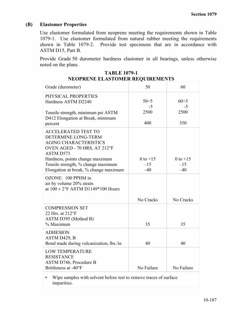
Section 1079
10-187
(B) Elastomer PropertiesUse elastomer formulated from neoprene meeting the requirements shown in Table1079-1. Use elastomer formulated from natural rubber meeting the requirementsshown in Table 1079-2. Provide test specimens that are in accordance withASTM D15, Part B.Provide Grade 50 durometer hardness elastomer in all bearings, unless otherwisenoted on the plans.
TABLE 1079-1NEOPRENE ELASTOMER REQUIREMENTS
Grade (durometer) 50 60
PHYSICAL PROPERTIESHardness ASTM D2240
Tensile strength, minimum psi ASTMD412 Elongation at Break, minimumpercent
50+5 -52500
400
60+5 -52500
350
ACCELERATED TEST TODETERMINE LONG-TERMAGING CHARACTERISTICSOVEN AGED - 70 HRS, AT 212°FASTM D573Hardness, points change maximumTensile strength, % change maximumElongation at break, % change maximum
0 to +15–15–40
0 to +15–15–40
OZONE: 100 PPHM inair by volume 20% strainat 100 ± 2°F ASTM D1149*100 Hours
No Cracks No Cracks
COMPRESSION SET22 Hrs. at 212°FASTM D395 (Method B)% Maximum 35 35
ADHESIONASTM D429, BBond made during vulcanization, lbs./in 40 40
LOW TEMPERATURERESISTANCEASTM D746, Procedure BBrittleness at -40°F No Failure No Failure
∗ Wipe samples with solvent before test to remove traces of surfaceimpurities.
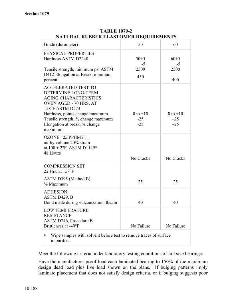
Section 1079
10-188
TABLE 1079-2NATURAL RUBBER ELASTOMER REQUIREMENTS
Grade (durometer) 50 60
PHYSICAL PROPERTIESHardness ASTM D2240
Tensile strength, minimum psi ASTMD412 Elongation at Break, minimumpercent
50+5 -52500
450
60+5 -52500
400
ACCELERATED TEST TODETERMINE LONG-TERMAGING CHARACTERISTICSOVEN AGED - 70 HRS, AT158°F ASTM D573Hardness, points change maximumTensile strength, % change maximumElongation at break, % changemaximum
0 to +10-25-25
0 to +10–25–25
OZONE: 25 PPHM inair by volume 20% strainat 100 ± 2°F. ASTM D1149*48 Hours
No Cracks No Cracks
COMPRESSION SET22 Hrs. at 158°F
ASTM D395 (Method B)% Maximum 25 25
ADHESIONASTM D429, BBond made during vulcanization, lbs./in 40 40
LOW TEMPERATURERESISTANCEASTM D746, Procedure BBrittleness at -40°F No Failure No Failure
∗ Wipe samples with solvent before test to remove traces of surfaceimpurities.
Meet the following criteria under laboratory testing conditions of full size bearings:Have the manufacturer proof load each laminated bearing to 150% of the maximumdesign dead load plus live load shown on the plans. If bulging patterns implylaminate placement that does not satisfy design criteria, or if bulging suggests poor

Section 1079
10-189
laminate bond, the bearing is rejected. If there are three separate surface cracks thatare greater than 0.08" wide and 0.08" deep, the bearing is rejected.Do not provide a bearing with a shear resistance, at 25% strain of the total effectiverubber thickness and after an extended four-day ambient temperature of -20°F,exceeding 50 psi for 50 durometer or 75 psi for 60 durometer Table A compounds, or30 psi for 50 durometer or 40 psi for 60 durometer for Table B compounds.
(C) Dimensional TolerancesProvide material with a flash tolerance, finish and appearance meeting therequirements of the Rubber Handbook, Second Edition as published by the RubberManufacturers Association, Inc.: RMA-F3-T.063 for molded bearings and RMA-F2for extruded bearings.Permissible variation from the dimensions and configuration required by the contractis indicated in Table 1079-3.
TABLE 1079-3Elastomer Bearing Tolerances
Overall vertical dimensions - 0, +1/16"Overall horizontal dimensions - 0, +1/4"Thickness of individual layers of elastomer (Laminatedbearings only)
± 1/16"
Variations from a plane parallel to the theoretical surface Top 1/8"Sides 1/4"
Edge cover of embedded laminates - 0, +1/8"Size of holes or slots - 0, +1/8"Position of holes or slots - 0, +1/8"Thickness of non-elastic laminates: - 0, +1/16"
(D) TestingFurnish all bearings that are produced by a bearing manufacturer who previouslysubmitted the required pre-qualification test samples and certifications and whoseelastomer formulation is initially approved for use by the Engineer. Obtain approvalfrom the Engineer for each elastomer formulation produced by a manufacturer priorto its first use on Department projects. To pre-qualify and obtain initial approval ofa particular formulation, have the bearing manufacturer submit to the Engineer, wellin advance of anticipated use of the product, certified test results showing actual testvalues obtained when the physical properties of the elastomer are tested forcompliance with the pertinent Specifications.In addition, have the manufacturer forward pre-qualification test samples to theEngineer for testing and evaluation of compliance with pre-qualificationrequirements. Include in the pre-qualification samples at least two finished bearingstypical of the formulation and workmanship intended for use on Department projects.Have the bearing manufacturer certify that all of the samples submitted are of thesame basic elastomer formulation and of equivalent cure to that used in the finishedproducts furnished on Department projects.

Section 1079
10-190
If required, have the producer perform the complete pre-qualification testingprocedure again during later production if the Engineer feels such action isappropriate.After pre-qualification approval, inspect, sample and test actual bearing production asoutlined below:Have the manufacturer furnish certified laboratory test results on the elastomerproperties of each batch or lot of compound used in the manufacture of bearings,both plain and laminated. Submit one sample bearing for each batch or lot ofcompound for verification testing.
SECTION 1080PAINT AND PAINT MATERIALS
1080-1 GENERALDeliver all paints except two component products to the project completely mixed and
ready for use without additional oil or thinner. Mix two component paints in accordancewith the manufacturer's printed instructions and shall not need additional oil or thinner uponmixing, except where necessitated by weather conditions. Mixed paints or paintcomponents that harden or curdle in the container and will not break up with a paddle toform a smooth, uniform consistency will be rejected. Any thinning necessitated by weatherconditions shall be approved in writing and use only those thinners approved by themanufacturer. Store all paint materials in a moisture free environment between 40°F and110°F or at such temperatures within this range recommended by the manufacturer.1080-2 PAINT VEHICLES, THINNERS, AND DRIERS
Paint vehicles, thinners, and dryers shall meet the requirements for these ingredients thatare included in the Specifications for the paint being used. Only ingredients recommendedby the manufacturer which have a history of compatibility with each other may be used.1080-3 PACKING AND MARKING
Ship paint and paint materials in strong, substantial containers, that are properly labeledand plainly marked with the weight, color, and volume in gallons of the paint content; a truestatement of the percentage composition of the pigment; the proportions of pigment tovehicle; and the name and address of the manufacturer. Any package or container not somarked as described above or exceeding 5 gallons total volume will not be accepted for use.1080-4 INSPECTION AND SAMPLING
Inspection and sampling will be made at the point of manufacture wherever possible.The right is reserved to sample all paint, either at the destination or at the point of origin,and to withhold acceptance of the paint until analysis of such samples have been made.
Use only pre-qualified inorganic zinc paint manufactured in accordance with therequirements shown below.
Have the paint manufacturer submit the following at the same time to the State MaterialsEngineer:

Section 1080
10-191
(A) A minimum one quart sample of each component of paint including themanufacturer's name, location, product name, mixing instructions, batch number, andMSDS information.
(B) A minimum of three panels prepared as specified in 5.5.10 of AASHTO M-300,Bullet Hole Immersion Test.
(C) A certified test report from an approved Independent Testing Laboratory for the SaltFog Resistance Test and Cyclic Weathering Resistance Test specified in 5.5.8 and5.5.9 of AASHTO M-300, respectively.
(D) A certified report from an approved Independent Testing Laboratory that the producthas been tested for Slip Coefficient and meets the requirements set forth forAASHTO M253 Class B.
Use the same batch of paint for all samples and panels. The Independent TestingLaboratory Report may be for a typical batch of the same product. Submit samples andreports for qualification at least 30 days in advance of anticipated need. Once qualified,a product will be placed on North Carolina's approved list for a period of 5 years unless theformulation of the product or manufacturing process is changed, in which case the productshall be requalified before use.
The Materials and Tests Unit will conduct all tests of paints in accordance with the latesttest methods of the American Society for Testing and Materials, Federal Test MethodStandard No. 141, and various other methods in use.1080-5 RED PRIMER PAINT(A) SCOPE
This Specification covers a long oil-alkyd primer paint for use on steel surfaces blast-cleaned to a SSPC SP-6 finish. The paint may be applied by brushing or spraying toa wet film thickness of approximately 3 wet mils per coat.
(B) MATERIALSMaterials shall be as specified herein. Materials not specified shall be selected by thesupplier and will be subject to all of the requirements of this Specification. Use paintmade of materials that are not toxic to personnel under normal conditions of use andwhich contain no more than 2.8 pounds per gallon volatile organic compounds.

Section 1080
10-192
(1) PAINT CHARACTERISTICSMINIMUM MAXIMUM
Pigment % by weight 53 55Vehicle % by weight 47Weight per gallon 12.9 lbs.Solids % by volume 67.0Fineness of grind Hegman units 4.5Moisture content % by weight 0.5Skinning hrs (3/4 vol. in closed container) 48Viscosity 85 KU 95 KUDrying time, set to touch 6 HrsDrying time, dry through 18 Hrs* Adhesion at 14 days (ASTM D-3359) 3BVolatile Organic Compounds per Gallon 2.8 lbs.
(2) PIGMENT COMPOSITION (% by weight)MINIMUM MAXIMUM
Zinc Hydroxy Phosphite ASTM D-4462-85 73Red Iron Oxide (86% Fe2O3) 24Organo Montmorillonite 1
(3) VEHICLE COMPOSITION (% by weight)MINIMUM MAXIMUM
Non-Volatile 62Alkyd resin solids Fed. Spec TT-4-266, Type 1, Class A
40
Linseed oil (ASTM D-234) 20Linseed oil to Alkyd ratio 1.2Thinner and Dryer Thinner: Fed. Spec. TT-T291, Type 2 Gr. A Dryer: Fed. Spec. TT-D-643B
38
* Prepare the specimen for the adhesion test by applying two dry mils of the coatingto a standard Q panel.
1080-6 ALKYD FINISH PAINT(A) SCOPE
This Specification covers a gray, long oil-alkyd primer paint for use over surfacescoated with Red Alkyd Primer Paint. The paint may be applied by brushing orspraying to a wet film thickness of approximately 3 wet mils per coat.
(B) MATERIALSMaterials shall be as specified herein. Materials not specified will be selected by thesupplier and be subject to all of the requirements of this Specification. Use paint
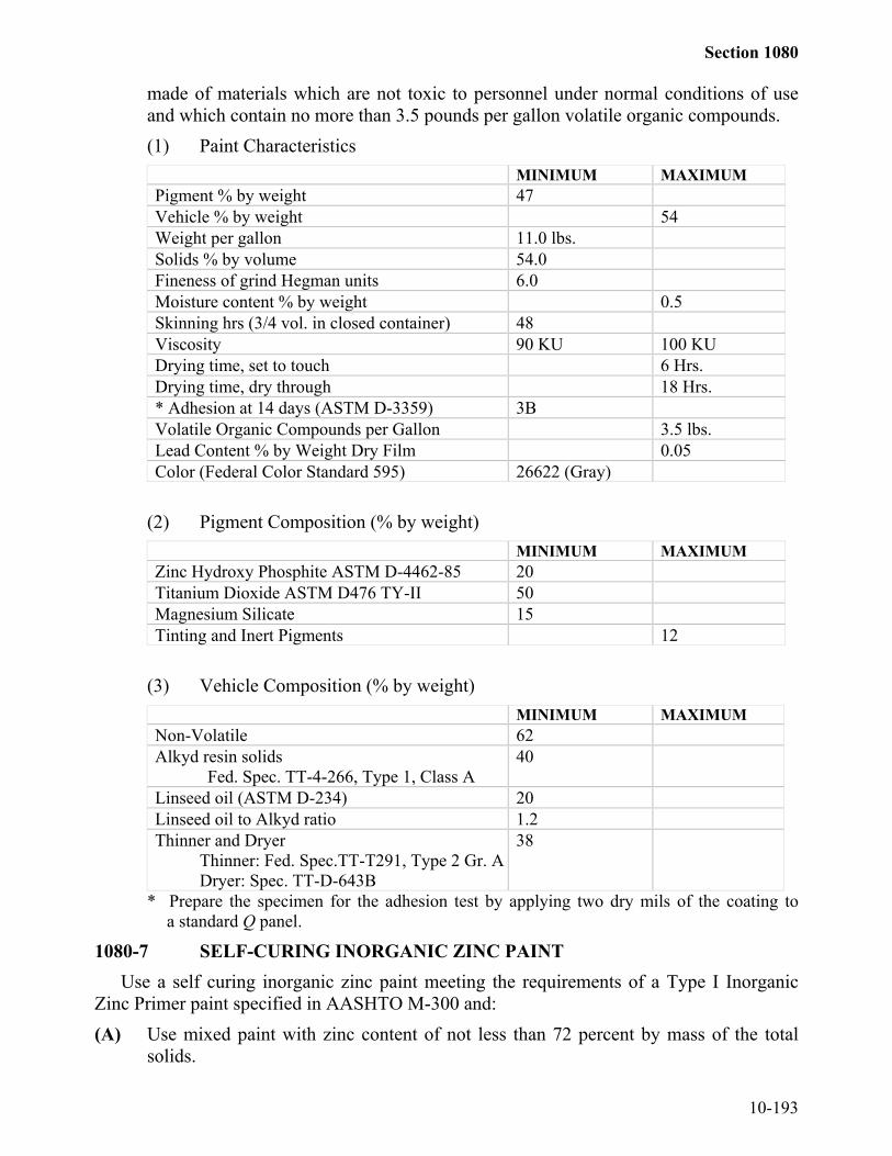
Section 1080
10-193
made of materials which are not toxic to personnel under normal conditions of useand which contain no more than 3.5 pounds per gallon volatile organic compounds.(1) Paint Characteristics
MINIMUM MAXIMUMPigment % by weight 47Vehicle % by weight 54Weight per gallon 11.0 lbs.Solids % by volume 54.0Fineness of grind Hegman units 6.0Moisture content % by weight 0.5Skinning hrs (3/4 vol. in closed container) 48Viscosity 90 KU 100 KUDrying time, set to touch 6 Hrs.Drying time, dry through 18 Hrs.* Adhesion at 14 days (ASTM D-3359) 3BVolatile Organic Compounds per Gallon 3.5 lbs.Lead Content % by Weight Dry Film 0.05Color (Federal Color Standard 595) 26622 (Gray)
(2) Pigment Composition (% by weight)MINIMUM MAXIMUM
Zinc Hydroxy Phosphite ASTM D-4462-85 20Titanium Dioxide ASTM D476 TY-II 50Magnesium Silicate 15Tinting and Inert Pigments 12
(3) Vehicle Composition (% by weight)MINIMUM MAXIMUM
Non-Volatile 62Alkyd resin solids
Fed. Spec. TT-4-266, Type 1, Class A40
Linseed oil (ASTM D-234) 20Linseed oil to Alkyd ratio 1.2Thinner and Dryer
Thinner: Fed. Spec.TT-T291, Type 2 Gr. ADryer: Spec. TT-D-643B
38
* Prepare the specimen for the adhesion test by applying two dry mils of the coating toa standard Q panel.
1080-7 SELF-CURING INORGANIC ZINC PAINTUse a self curing inorganic zinc paint meeting the requirements of a Type I Inorganic
Zinc Primer paint specified in AASHTO M-300 and:(A) Use mixed paint with zinc content of not less than 72 percent by mass of the total
solids.

Section 1080
10-194
(B) The Slip Coefficient meets the requirements set forth for AASHTO M253 Class B.(C) The elcometer adhesion when performed in accordance with ASTM D-4541 shall be
no less than 400 psi.(D) Cure the paint to meet the solvent rub requirements in ASTM D 4752.(E) Formulate the paint so as to produce a distinct contrast in color with the blast cleaned
metal surfaces and with the finish paint.1080-8 COAL TAR EPOXY PAINT
Use coal tar epoxy paint meeting the requirements of Steel Structures Painting CouncilSSPC Paint 16.1080-9 ORGANIC-ZINC REPAIR PAINT
Use organic-zinc repair paint meeting the requirements of SSPC Paint 20 Type II, orFederal Specification TT-P-641. Organic-zinc repair paint is not tinted and is applied3 – 4 wet mils of paint per coat. Do not use zinc paint in aerosol spray cans.1080-10 WASH PRIMER PAINT
Use wash primer paint meeting the requirements of Society of Protective CoatingsSSPC Paint 27.1080-11 BLANK1080-12 WATERBORNE PAINTS(A) Paints
(1) Waterborne Primer Paints The chemical requirements of the brown and whiteprimer paints are specified in Tables 1080-1(A) through (D). Use primerpaints on roughened steel surfaces cleaned to an SSPC SP-6 finish. Two coatsof paint are required to form an effective primer coat. The first coat is brownand the second is white. Each coat is applied at a wet film thickness ofapproximately 6 mils.
(2) Waterborne Finish Paints The chemical requirements of the gray and greenfinish paints are specified in Tables 1080-2(A) through (D). Apply finishpaints over compatible primer paints. Apply either one or two coats at a wetfilm thickness of approximately 6 mils each to produce an effective finishcoat.
(B) Description(1) The acrylic paints furnished in accordance with this Specification are one
component products made from acrylic resins with sufficient additives,coalescing agents, solvents and pigmentation to produce a durable paint witha volatile organic compound (VOC) content less than 2.0 lb./gal.
(2) These products are intended for brush, roller or spray application applied inaccordance with SSPC-PA 1, Shop, Field and Maintenance Painting.
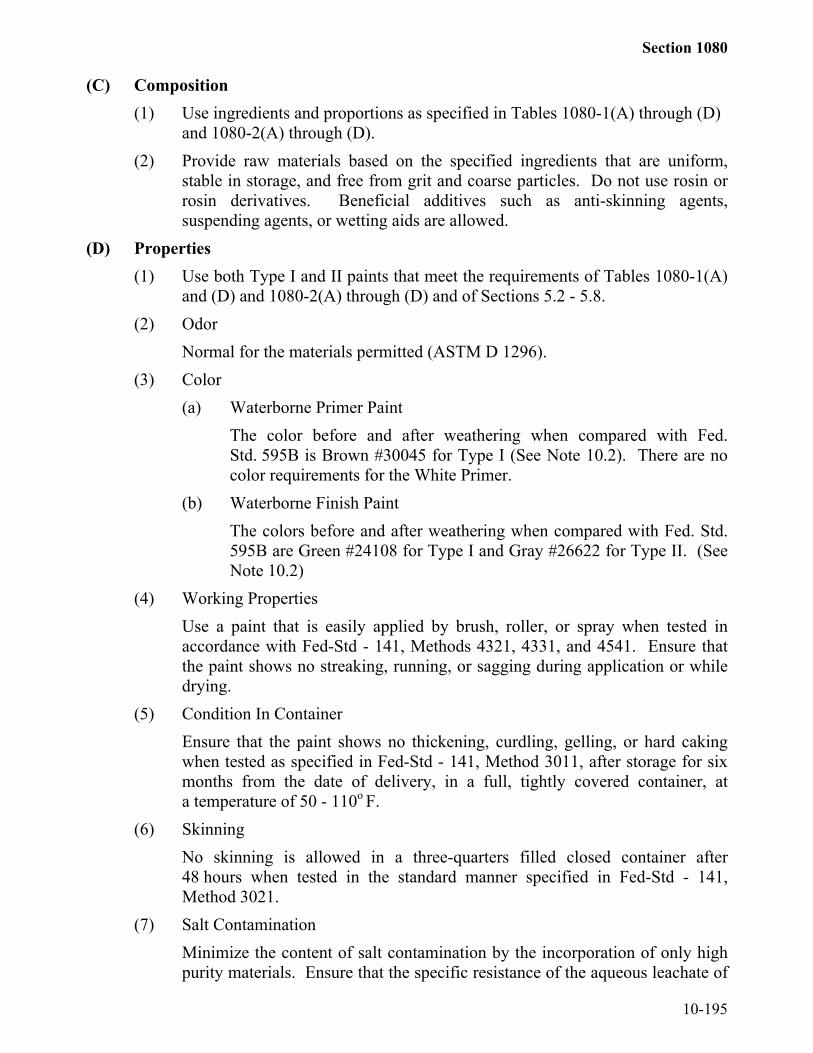
Section 1080
10-195
(C) Composition(1) Use ingredients and proportions as specified in Tables 1080-1(A) through (D)
and 1080-2(A) through (D).(2) Provide raw materials based on the specified ingredients that are uniform,
stable in storage, and free from grit and coarse particles. Do not use rosin orrosin derivatives. Beneficial additives such as anti-skinning agents,suspending agents, or wetting aids are allowed.
(D) Properties(1) Use both Type I and II paints that meet the requirements of Tables 1080-1(A)
and (D) and 1080-2(A) through (D) and of Sections 5.2 - 5.8.(2) Odor
Normal for the materials permitted (ASTM D 1296).(3) Color
(a) Waterborne Primer PaintThe color before and after weathering when compared with Fed.Std. 595B is Brown #30045 for Type I (See Note 10.2). There are nocolor requirements for the White Primer.
(b) Waterborne Finish PaintThe colors before and after weathering when compared with Fed. Std.595B are Green #24108 for Type I and Gray #26622 for Type II. (SeeNote 10.2)
(4) Working PropertiesUse a paint that is easily applied by brush, roller, or spray when tested inaccordance with Fed-Std - 141, Methods 4321, 4331, and 4541. Ensure thatthe paint shows no streaking, running, or sagging during application or whiledrying.
(5) Condition In ContainerEnsure that the paint shows no thickening, curdling, gelling, or hard cakingwhen tested as specified in Fed-Std - 141, Method 3011, after storage for sixmonths from the date of delivery, in a full, tightly covered container, ata temperature of 50 - 110o F.
(6) SkinningNo skinning is allowed in a three-quarters filled closed container after48 hours when tested in the standard manner specified in Fed-Std - 141,Method 3021.
(7) Salt ContaminationMinimize the content of salt contamination by the incorporation of only highpurity materials. Ensure that the specific resistance of the aqueous leachate of

Section 1080
10-196
the composite of the pigments in required proportions is a minimum of 5,000ohm-cm when tested in accordance with ASTM D 2448.
(8) Early Rust ResistanceProvide each type of paint that meets the early rust requirements specified inMaterials and Tests Standards CLS-P-1.0.
(9) Directions For UseSupply the following directions for use with each container of paint:Waterborne primer paint is intended for use as a primer over rough, barestructural steel. It is not intended for use over other paint systems.Waterborne finish paint is intended for use as a topcoat over a compatibleprimer in atmospheric exposure. Mix the paint thoroughly before use. Forroller, brush, or airless spray application, no thinning should be necessary.A minimum amount of thinning may be necessary for conventional air spray.Apply by brush or spray to the specified film thickness or, if none is specified,to at least 2 mils dry or approximately 6 mils wet. Dry the surface to bepainted and ensure that the surface temperature is a least 5o F above the dewpoint, the humidity is less than 85%, and the temperature of the air is over50o F. Do not paint outdoors in rainy weather or if freezing temperatures areexpected before the paint dries. Allow the paint at least 24 hours drying timebefore recoating.
(E) INSPECTION(1) All materials supplied under this Specification are subject to random
inspection by the Department. The Department has the right to reject anymaterials supplied that are found to be defective in accordance with Articles105-3 and 106-9.
(2) Supply samples of any or all ingredients used in the manufacture of this paint,along with the supplier's name and identification for the material whenrequested.
(F) VOLATILE ORGANIC COMPOUND (VOC) CONTENTEnsure that the VOC content after formulation (but before thinning) complies withthe VOC limit for the applicable coatings category per Federal regulations. Make thecoating specifier aware that more stringent state or local regulations may reduce themaximum VOC content permitted for coatings applied in a specific locality.
(G) COLOR VARIATIONA color variation of 5 delta e units from the specified color shall be acceptable. Afterthree months weathering the color shall not vary more than 5 delta e units from theoriginal color value.

Section 1080
10-197
TABLE 1080-1(A)ANALYSIS FOR WATERBORNE PRIMER PAINTS
R E Q U I R E M E N T SCHARACTERISTICS Min Wt % Max Wt % ASTMPigment Content Type I (Brown) Type II (White)
2035
2540
D 3723
Volatiles Type I (Brown) Type II (White)
--
2.0 lbs./gal D 2369
Coarse particles and skins, asretained on standard 325 meshscreen
- 0.5 D 185
Rosin or rosin derivatives - 0 D 1542
TABLE 1080-1(B)COMPOSITION OF WATERBORNE PRIMER PAINTS
TYPE I BROWN TYPE II WHITE TEST METHODSPIGMENTS Wt %
MinWt % Max Wt %
MinWt % Max ASTM/Federal/State
Major Pigments 20 25 35 40 D 3723Calcium Carbonate - 30 D 1159Magnesium Silicate 12 D 605Titanium Dioxide - 45 - D 476, Type IIZinc Phosphate 10 - 10 - NCDOT M&T P-10Iron Oxide 45 ASTM D 3721Tinting PigmentsLamp Black - 2% - ASTM D 209PhthalocyaninePigments
2% ASTMD1135 & D3256
Acid SolublePigments1
- - - 0
Lead - 0.005 - 0.005
TABLE 1080-1(C)VEHICLE Wt % Min Wt % Max Wt %
MinWt % Max TEST METHODS
Total Vehicle 73 80 60 65 NCDOT M&T P-10HG-56 3 Solids 30 - 30 -Water - 55 - 55Methyl Carbitol 5 - 5 -Texanol 2 - 2 -
1. Use a 5% acetic acid solution with a pH 4 + 2 to determine solubility.2. Do not use chrome green.3. Or approved equivalent.

Section 1080
10-198
TABLE 1080-1(D)PROPERTIES OF WATERBORNE PRIMER PAINTS
R E Q U I REMENTSCHARACTERISTICSMIN MAX
ASTM/FEDERAL
Consistency* Sheer Rate 200 r/minOunces
Krebs units2553.2
3503.5
D 562
Density, lb./US galType I (Brown)Type II (White)
9.711.0
--
D 1475
Fineness of Grind, Hegman Units 5.0 - D 1210Drying Time, Hours
Tack FreeDry Hard
--
324
D 1640
Flash Point, oF Report Value Report Value D 3278Early Rust 9 - Section 5.8
Leneta Sag Test 10+Gloss, Specular @ 60 degrees Report Value Report Value
pH 8.0 8.5Adhesion (1) 4B D 3359
ColorType I (Brown)
Type II (White)
FED-STD 595B30045
NA
D 2244
(1) Prepare the specimen for adhesion by applying 2 dry mils of coating to a 3”x 5”x 0.25” steelpanel cleaned to a minimum SSPC SP-6 finish with a 1.7 + 0.5 mil profile.
* Consistency 48 hours or more after manufacture.TABLE 1080-2(A)
ANALYSIS FOR WATERBORNE FINISH PAINTSREQUIREMENTS
CHARACTERISTICS Min Wt % Max Wt % ASTMPigment Content Type I (Green) Type II (Gray)
1313
1717
D 3723
Volatiles Type I (Green) Type II (Gray)
--
2.0 lbs./gal D 2369
Coarse particles and skins, asRetained on standard 325 mesh screen - 0.5 D 185Rosin or rosin derivatives - 0 D 1542
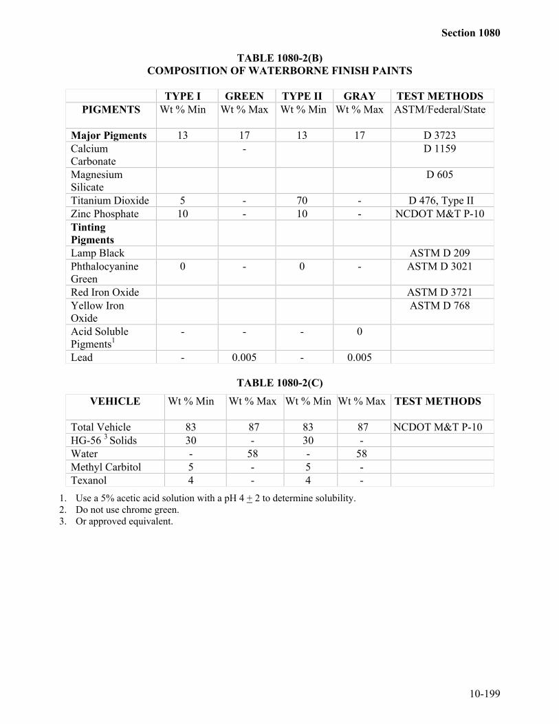
Section 1080
10-199
TABLE 1080-2(B)COMPOSITION OF WATERBORNE FINISH PAINTS
TYPE I GREEN TYPE II GRAY TEST METHODSPIGMENTS Wt % Min Wt % Max Wt % Min Wt % Max ASTM/Federal/State
Major Pigments 13 17 13 17 D 3723CalciumCarbonate
- D 1159
MagnesiumSilicate
D 605
Titanium Dioxide 5 - 70 - D 476, Type IIZinc Phosphate 10 - 10 - NCDOT M&T P-10TintingPigmentsLamp Black ASTM D 209PhthalocyanineGreen
0 - 0 - ASTM D 3021
Red Iron Oxide ASTM D 3721Yellow IronOxide
ASTM D 768
Acid SolublePigments1
- - - 0
Lead - 0.005 - 0.005
TABLE 1080-2(C)
VEHICLE Wt % Min Wt % Max Wt % Min Wt % Max TEST METHODS
Total Vehicle 83 87 83 87 NCDOT M&T P-10HG-56 3 Solids 30 - 30 -Water - 58 - 58Methyl Carbitol 5 - 5 -Texanol 4 - 4 -
1. Use a 5% acetic acid solution with a pH 4 + 2 to determine solubility.2. Do not use chrome green.3. Or approved equivalent.

Section 1080
10-200
TABLE 1080-2(D)PROPERTIES OF WATERBORNE FINISH PAINTS
R E Q U I R E M E N T SCHARACTERISTICS MIN MAX ASTM/FEDERALConsistency* Sheer Rate 200 r/min Grams Krebs units
25590
350100
D 562
Density, lb./US gal Type I (Green) Type II (Gray)
9.359.35
--
D 1475
Fineness of Grind, Hegman Units 5.0 - D 1210Drying Time, Hours Tack Free Dry Hard
--
324
D 1640
Flash Point, oF Report Value Report Value D 3278Early Rust 9 - Section 5.8Leneta Sag Test 10+Gloss, Specular @ 60 degrees 40pH 8.0 8.5Adhesion (1) 4B D 3359Color Type I (Green) Type IB(NC Green) Type II Gray)
Fed-Std 595B241082427226622
D 2244
(1) Prepare the specimen for adhesion by applying 2 dry mils of coating to a 3”x 5”x 0.25” steelpanel cleaned to a minimum SSPC SP-6 finish with a 1.7 + 0.5 mil profile.
*Consistency 48 hours or more after manufacture.
1080-13 BLANK1080-14 PAINT FOR VERTICAL MARKERS
For vertical markers, use a waterborne acrylic or alkyd type material meeting thefollowing requirements:(A) Color...Federal Color Std. 595 ……………………# 27040 Black or # 13538(B) Adhesion to Substrate (ASTM D3350) …….…… 3A Min.
Apply sufficient paint to completely cover the color of the underlying substrate alongwith any surface imperfections.1080-15 ABRASIVE MATERIALS FOR BLAST CLEANING STEEL
Select the gradation of the abrasive to impart the anchor profile specified.Alternative A - Expendable Abrasive
Use blasting abrasives with a suitable steel or mineral abrasive which contain no morethan 100 ppm of any corrosive compound such as sulfate or chloride or 100 ppm of anyEPA characteristic waste compound such as lead, chromium, or arsenic.

Section 1080
10-201
Alternative B - Recyclable Steel GritUse abrasives that when sampled at any time during the blasting process, contain nomore than 100 ppm of any corrosive compound such as sulfate or chloride or 1000 ppmof any EPA characteristic waste compound such as lead, chromium or arsenic. Maintainthe size and shape of the abrasive to impart the specified profile.
1080-16 FIELD PERFORMANCE AND SERVICEDo not use paint products inspected by the Engineer and found to exhibit poor
performance in similar North Carolina environments. Poor performance is defined as anycoating failing to meet ASTM D610, Grade 5, or having greater than 3% rusting ordisbonding before attaining 5 years of service.
SECTION 1081EPOXY AND ADHESIVES
1081-1 EPOXIES - GENERALThe types of epoxies and their uses are as shown below:Type 1. A low-modulus, non-sag gel adhesive used to bond or repair damp, vertical,
or overhead surfaces. Typical applications include walls, concretefoundations, concrete pipe, conduit, and ceilings.
Type 2: A low-modulus, general-purpose adhesive used in epoxy mortar repairs andbroadcast sand sealing operations. Bridge Maintenance uses it as both aprimer coat and thickness-building second coat in two-stage sand broadcastoperations to seal and skid-proof bridge decks. As a repair material, it maybe used to patch spalled, cracked, or broken concrete where vibration, shock,or expansion and contraction is expected. Feather-edged patching is notrecommended with this material; instead, the adjacent concrete perimetershould be sawed at least 1/4" to 1/2" deep and any remaining concretechipped away to provide a vertical interface between the epoxy mortar andconcrete.
Type 3. A high-modulus general-purpose adhesive used to bond plastic concrete orhardened concrete to hardened concrete or other structural materials. It mayalso be used to produce a high-strength epoxy mortar grout bed forequipment or to patch interior spalls, cracks, or broken concrete. It is notrecommended for exterior patching because its rate of thermal expansion andcontraction differs too greatly from concrete. It may be used for anchoringbolts where a flowable adhesive is required.
Type 3A. A gel-like version of Type 3, used specifically for embedding dowel bars,threaded rods, rebars, and other fixtures in hardened concrete. Themanufacturer shall submit test results showing that the bonding system willobtain 125% of the specified yield strength of the anchor fixture in concretewith a minimum compressive strength of 3000 psi. Plans may call for fieldtesting of adhesively anchored fixtures.

Section 1081
10-202
Type 4A. A gray protective coating for concrete, wood, steel and other structuralmaterials. It is typically used as a topcoat in waterproofing concrete exposedto splash zones and tidal water.
Type 4B. A red primer coating used with Type 4A.Type 5. A high modulus, low viscosity adhesive suitable for pressure injection into
cracks in concrete. For some non-structural crack repairs, Type 5 epoxy maybe poured on the surface to penetrate cracks by gravity. This may bebeneficial before waterproofing and skid proofing.
Type 6A. An adhesive for bonding raised traffic markers to concrete or asphaltsurfaces. Part A shall be pigmented white, Part B black so that when thecomponents are combined a uniform gray color results.
Type 6B. A normal-setting self-leveling adhesive for bonding traffic markers inrecessed areas on concrete and asphalt. Type 6A color requirements apply.
Type 6C. A rapid-setting adhesive for bonding traffic markers to concrete and asphaltsurfaces. Type 6A color requirements apply.
1081-2 SPECIFICATIONS FOR USE OF EPOXIES(A) Supply
Supply epoxy resin in two components, labeled as Component A -- Contains EpoxyResin and Component B -- Contains Curing Agent, for combining immediately priorto use in accordance with the manufacturer's instructions. Mark each container withthe manufacturer's name, NCDOT type, lot or batch number, quantity, date ofmanufacture, shelf life or expiration date, color, mixing instructions, usabletemperature range, and hazards or safety precautions.Furnish the two components in separate non-reactive containers. Provide containersof such size that the proportions of the final mix can be obtained by combining asingle container of one component with one or more whole containers of the othercomponent.
(B) AcceptanceThe Materials and Tests Unit maintains an approved list of epoxies identified bybrand name and Department type. When materials on this list are furnished to aproject, submit to the Engineer a Type 1, Certified Mill Test Report for each lot orbatch. Materials not on this list shall be tested by the Department prior to use, inwhich case the manufacturer shall furnish samples and a Type 1 certification to theMaterials and Tests Unit. The sample size for a 1:1 mix ratio will be one gallon percomponent; for different mix ratios, the sample size of the greater component will beincreased proportionally. When materials are furnished to the Bridge MaintenanceUnit, the terms of acceptance will be listed in the bid solicitation. The Engineerreserves the right to reject any epoxy that does not perform adequately in the field.
(C) Fillers, Pigments, and Thixotropic AgentsAll integral fillers, pigments, and thixotropic agents shall be fine enough to notseparate, settle, or cause skinning during storage of the epoxy components. Do not

Section 1081
10-203
use abrasive fillers such as alumina and silica flour. Do not use solvents. Whenmineral fillers are to be added during mixing, they shall be inert, readily dispersible,and, except for sand, have fineness such that 99% of the material will pass a No. 325sieve.
(D) Shelf lifeThe shelf life of parts A and B shall be a minimum of 1 year from the date ofmanufacture.
1081-3 NOTES ON USE OF EPOXIES(A) Moisture Conditions
Types 1 - 5 are moisture insensitive and can be applied on clean, dry, or dampsurfaces free of standing water.
(B) Coefficient of ExpansionThe coefficient of expansion of cured epoxy is 6 times greater than that of concrete.Therefore, to reduce spalling and peeling during temperature changes, avoid thicklayers of pure epoxy. A 4:1 by weight sand-epoxy mortar has approximately thesame coefficient of expansion as concrete.
(C) SafetyEpoxies can irritate the eyes, skin, and respiratory tract. Therefore, wear chemicalsplash goggles, chemically-resistant gloves, and protective clothing and boots whenhandling epoxies. Respiratory protection is usually not needed if epoxies are mixedand applied in well-ventilated areas, but avoid prolonged breathing of vapors.Follow all Material Safety Data Sheet instructions for proper use of these materials.
(D) MixingStir parts A and B individually until each component is homogeneous. Use aseparate stirrer for each component.Combine parts A and B, either by weight or volume, as specified in themanufacturer's instructions. Stir the mixture vigorously, periodically scraping thesides and bottom of the container. Small quantities of epoxy usually require 2-3minutes to mix homogeneously; 5-gallon quantities can take up to 10 minutes ofmixing.Temperature affects the viscosity and pot life of epoxies. Most laboratory tests areconducted at 77°F. Higher temperatures render epoxies thinner and faster setting;lower temperatures induce higher viscosities and longer pot lives.Add sand or other fillers to liquid epoxies only after parts A and B have beenthoroughly mixed. Stir in the sand or filler until all particles are completely coated.
(E) Storage and Substrate Temperature
Store epoxies at temperatures between 50°F and 90°F. Epoxy components exposedto the extremes of this range or outside this range should be conditioned to 77°F

Section 1081
10-204
before mixing and blending. If heat is necessary, always use indirect methods suchas hot water, a heated room, or a microwave oven to condition components.
When applying epoxy to a cold substrate, preheat the components approximately 1°Fabove 77°F for every 2°F of substrate temperature below 77°F.Seal previously opened containers to be airtight. Unsealed containers can absorbmoisture from the atmosphere, which can alter the chemical reaction of the mixture.
1081-4 TEST METHODS FOR EPOXIES(A) Viscosity
Determine the viscosity of the mixture in accordance with ASTM D 2669, usingBrookfield viscometer model RVT. Use the spindle number and speed shown inTable 1081-1.
(B) Pot LifeDetermine the pot life of the mixture in accordance with AASHTO T 237 except usea mass of 60 + or - 0.4g.
(C) Compressive Strength of Epoxy MortarDetermine the compressive strength of epoxy mortar in accordance withASTM C 109 except as follows:Use mortar consisting of one part epoxy and three parts standard graded Ottawa sandexcept for Types 1 and 3A, which shall be tested neat. Mix epoxy components A andB at the recommended proportions for 2 minutes, add the sand, and mix for 3minutes. Pour the mortar into the cube molds in 2 layers, and tamp each layer 50times with a spatula and 25 times with a hammer handle. Make 6 specimens, andcure all in air at 77 + or - 2°F for 24 hours. Test 3 specimens for compressivestrength at the end of this curing period. Immerse the remaining 3 specimens inwater at + 77°F for 6 days, after which immediately test them for compressivestrength in the wet condition.
(D) Volatiles ContentDetermine the percentage of volatiles in the mixture in accordance withASTM D 1078.
(E) Ash ContentDetermine the ash content of the mixture in accordance with ASTM D 482.
(F) Tensile Strength and Tensile ElongationDetermine the tensile strength and tensile elongation of the mixture in accordancewith ASTM D 638.
(G) HardnessDetermine the Shore D hardness of the mixture at 24 hours and 7 days in accordancewith ASTM D 2240.

Section 1081
10-205
(H) AbsorptionDetermine the water absorption of the mixture in accordance with ASTM D 570.
(I) Bond StrengthDetermine the bond strength of the moist-cured mixture at 14 days by the slant sheartest, ASTM C 882.
1081-5 PROPERTIES OF EPOXIESEpoxies shall conform to the requirements shown in Table 1081-1.
1081-6 POLYESTER RESIN EPOXY ADHESIVE(A) General
Polyester resin is used specifically for embedding dowel bars, threaded rods, rebars,and other fixtures in hardened concrete.Have the manufacturer submit test results showing that the bonding system willobtain 125% of the specified yield strength of the anchor fixture in concrete with aminimum compressive strength of 3000 psi. Field testing may be required foradhesively anchored fixtures.
(B) MaterialsPackage components of the adhesive in containers of such size that one wholecontainer of each component is used in mixing one batch of adhesive. Use containersof such design that all of the contents may be readily removed, and are well sealed toprevent leakage. Furnish adhesive material that requires hand mixing in two separatecontainers designated as Component A and Component B. A self contained cartridgeor capsule will consist of two components which will be automatically mixed as theyare dispensed, as in the case of a cartridge, or drilled into, as in the case of a capsule.Clearly label each container with the manufacturer's name; date of manufacture;batch number; batch expiration date; all directions for use and such warning ofprecautions concerning the contents as may be required by State or Federal Laws andRegulation.
(C) Mixing of AdhesiveMix adhesive in strict conformance with the manufacturer's instructions.
1081-7 HOT BITUMENThe adhesive shall be an asphaltic material with a homogeneously mixed filler and
comply with the following requirements:

Section 1081
10-206
(A) Physical Requirements(1) Adhesive Properties determined on the asphaltic material with filler.
MIN. MAX. TEST METHODSoftening point, °F. 200 -- ASTM D 36Penetration, 100 g., 5 sec., 77 °F 10 18 ASTM D 5Flow, Inch -- 0.2 ASTM D 5329
(as modified intest methods)
Viscosity, 400 °F, Poises -- 75 ASTM D 2669or D 4402
(as modified intest methods)
Flash Point, C.O.C., °F. 550 -- ASTM D 92
(2) Asphalt Properties determined on the filler-free material derived from theextraction and Abson recovery process as explained in Test Methods.
MIN. MAX. TEST METHODPenetration, 100 g., 5 sec., 77 °F 25 -- ASTM D 5Viscosity, 275 °F Poises 12 -100 ASTM D 2171Viscosity Ratio, 275 °F 2.2 (as explained
in test methods)
(3) Filler Properties determined using the filler separation techniques described inTest Methods.
MIN. MAX. TEST METHODFiller Content, % by weight, 65 75 (as described in
test methods)Filler Fineness, % passing ASTM C 430No. 325 75 (as modifiedNo. 200 95 in testNo. 100 100 methods)
(B) Test Methods(1) Flow
Determine flow according to Section 6, Flow, of ASTM D 3407 with theexception that the oven temperature shall be 158 ± 2 °F and samplepreparation done according to Section 7.1 of ASTM D 5.
(2) ViscosityViscosity is to be determined according to ASTM D 2669 using a spindlespeed of 10 rpm. Heat the adhesive to approximately 410°F and allowed tocool. Determine viscosity at 400 ± 1°F.

Section 1081
10-207
(3) Asphalt PropertiesProperties of the base asphalt are to be determined on the material obtainedfrom the following extraction and Abson recovery methods. Extract theasphalt by heating the adhesive just to the point where it will easily flow andthen transfer 125 to 150 grams into 400 ml of trichloroethylene with atemperature of 125°F to 150°F to 66°C). Thoroughly stir this mixture todissolve the asphalt. Decant the trichloroethylene-asphalt mixture decantedand the asphalt recovered using the Abson recovery method, ASTM D 1856 asmodified by the following. The extraction methods of ASTM D 2711 do notapply and there will be no filtration of the solvent asphalt mixture. Theextraction solution of trichloroethylene and asphalt shall be centrifuged for atleast 30 minutes at 770 times gravity in a batch centrifuge. Decant thissolution in the distillation flask, taking care not to include any filler sediment.Apply heat and bubble carbon dioxide solution slowly to bring the solutiontemperature to 300°F. At this point the carbon dioxide flow is increased to800 to 900 ml per minute. The solution temperature is maintained at 320°F to335°F with this carbon dioxide flow for at least 20 minutes and until thetrichloroethylene vapors have been completely removed from the distillationflask. Repeat the above extraction-recovery method as necessary to obtain thedesired quantity of asphalt. Use the asphalt recovered to determinepenetration, 275°F viscosity, and 275°F viscosity ratio.
(4) Viscosity Ratio
Determine the 275°F viscosity ratio by comparing the 275 °F viscosity on thebase asphalt before and after the Thin-Film Oven Test. Perform the Thin-FilmOven Test as in ASTM D 1754. Determine the specific gravity bypycnometer as in ASTM D 70 for use in the Thin-Film Oven Test. Calculatethe 275°F viscosity ratio by dividing the viscosity after the Thin-Film OvenTest by the original 275°F viscosity.
(5) Filler MaterialSeparate the filler material from the asphalt to determine Filler Content andFiller Fineness. Determine the portion by weight of the adhesive insoluble in1,1,1-trichloroethane by weighing 10.00 ± 0.01 grams of solid adhesive into acentrifuge flask with approximately 100 ml volume such as that specified inASTM D 1796. Add 50 ml of 1,1,1-trichloroethane to the adhesive, whichshould be broken up in small pieces in order to speed up the dissolution solids.Place the sample flask in a balanced centrifuge and spin using a minimumrelative centrifugal force of 150 (as determined in Section 6 ofASTM D 1796) for 10 minutes. Remove the sample flask and decant thesolid, taking care not to lose any solids. Repeat the application of solvent andcentrifuging until the solvent becomes clear and the filler is visually free ofasphalt. Dry the filler at 160 ± 5°F to remove solvent and weigh the resultingfiller. Filtration of the decanted solvent may be performed to verify there isno loss of filler. Percent filler content is calculated as follows:

Section 1081
10-208
(Filler, Wt, gm.) (100)Filter Content, % by weight = Original Adhesive Wt., gm.
Determine Filler Fineness according to ASTM C 430 using number 325, 200and 100 sieves. This method is to be modified by using a water soluble non-ionic wetting agent, such as Triton X-100, to aid the wetting action.Concentration of the surfactant solution shall be approximately 1% by weight.Thoroughly wet the one-gram dry sample in the surfactant solution andallowed to soak for 30 minutes. Transfer the filler completely into the sievecup and apply water spray for 2 minutes. Surfactant solution may be added asneeded and physical means used to disperse any clumped particles. Dry thesample and handle as described in ASTM C 430.
(C) PrequalificationBituminous adhesives are required to be pre-qualified by the Department’sTransportation-Traffic Engineering Branch. For more information on the pre-qualification process contact the Traffic Engineering Branch-Traffic Control Section.
(D) Packaging and LabelingPack the adhesive in self-releasing cardboard containers which will stack properly.Containers shall have a net weight of 50 to 60 pounds and contain 2 to 4subcompartments. Have the label show the manufacturer, quantity, and batchnumber. Print Bituminous Adhesive for Pavement Markers or similar wording on thelabel.
(E) CertificationA certification from the manufacturer showing the physical properties of thebituminous adhesive and conformance with the Specifications will be required.Supply certification prior to use.
(F) ApplicationApply the adhesive according to the manufacturer's requirements and the followingrequirements.Apply the adhesive when the road surface, ambient air and pavement markertemperatures are in the range of 50°F to 160°F on dry pavement.The composition of the adhesive shall be such that its properties will not deterioratewhen heated to and applied at temperatures up to 425°F using either air or oil-jacketed melters.Melt and heat the bituminous adhesive in either thermostatically controlled doubleboiler type units using heat transfer oil or thermostatically controlled electric heatingpots. Do not use direct flame units.
Heat the adhesive to between 375°F and 425°F and applied directly to the pavementsurface from the melter/applicator by either pumping or pouring. Maintain the

Section 1081
10-209
application temperature between 375°F and 425°F as lower temperatures may resultin decreased adhesion while higher temperatures may damage the adhesive.Use sufficient adhesive to insure total contact with the entire bottom of the pavementmarker. Apply pavement markers to the adhesive immediately (within 5 seconds) toassure bonding. Place the pavement marker in position by applying downwardpressure until the marker is firmly seated with the required adhesive thickness andsqueeze-out. Remove excessive adhesive squeeze-out from the pavement andimmediately remove adhesive on the exposed surfaces of pavement markers. Softrags with mineral spirits conforming to Federal Specifications TT-T-291 or kerosenemay be used if necessary, to remove adhesive from exposed faces of pavementmarkers. No other solvent may be used.Do not waste or spill any excess adhesive on Department right-of-way. Remove andproperly dispose of any adhesive spilled or dumped at such location. The Contractorat no cost to the Department will correct any damage incurred to the Department,highway or appurtenances as a result of misplaced adhesive.The adhesive may be reheated and reused. However, the pot life at applicationtemperatures shall not exceed the manufacturer's recommendations.Clean out of equipment and tanks may be performed using petroleum solvents suchas diesel fuel or similar materials. All solvents shall be removed from the equipmenttanks and lines before the next use of the melter.

Section 1081
10-210
BOND STRENG
THSLANT SH
EAR TEST:PSI (M
Pa) @ 14 DAYS
ASH CO
NTENT % M
AX
WATER ABSO
RPTION
% M
AX.
SHO
RE HARDNESS
@ 24 H
RS@
7 DAYS
COM
PRESSIVESTRENG
TH:
PSI (MPa) O
F 2 inM
ORTAR CUBES
@ 24 H
RS.@
7 DAYS
TENSILE ELONG
ATION
% AT 7 DAYS
TENSILE STRENGTH
PSI (MPa) AT 7 DAYS
POT LIFE (M
INUTES)
VISCOSITY-PO
ISES @77°F ± 2°F ± (25°C ±1°C)SPINDLE NO
.SPEED (RPM
)
TYPEPRO
PERTY
1500
30 1.5
6070
NEAT
30005000
30
1500
20 50
GEL 1M
in Max
1500 2.0 1.0
6070
4000
30 2000
3060
10 30
320 2M
in Max
2000 2.0 1.0
7080
6000
2 5
4000
20 50
25 75
420 3M
in Max
2000 50 1.5
7080
NEAT
6000
2 5
4000
5 50
GEL
3AM
in Max
1500
1030
1.0
6575
3000
5 15
1500
40 80
40 150
410 4AM
in Max
1500
10 30 1.0
6575
30005000
5 15
1500
40 80
40 150
410 4BM
in Max
1500 2.0 1.0
7080
6000
2 5
4000
20 60
1 6
250 5M
in Max
8 13
1500 3000
with helipathstand TD @
5
6AM
in Max
8 13
400 800
610 6BM
in Max
7 10
1500 3000
with helipathstand @
5
6CM
in Max
TA
BL
E 1081-1
PRO
PER
TIE
S OF E
POX
Y

Section 1081
10-211
SECTION 1082STRUCTURAL TIMBER AND LUMBER
1082-1 GENERALAll timber and lumber shall be Southern Pine and be graded in accordance with the
current grading rules of the Southern Pine Inspection Bureau unless otherwise specified orapproved by the Engineer. Stress rated grades of Southern Pine other than those specifiedmay be used provided the grades used have a stress rating equal to or higher than the gradesspecified, except that for temporary crossings, the use of stress rated lumber having stressratings below those specified may be used subject to the approval of the Engineer.
Have all timber and lumber, including any preservative treatment, inspected and/ortested at no cost to the Department by an approved commercial inspection company beforeit is delivered to the project. Provide industry standard commercial inspection reports foreach shipment of untreated timber or lumber prior to its use on the project. Provide industrystandard commercial inspection reports and treatment test reports for each shipment oftreated timber or lumber prior to its use on the project. Perform all timber and lumbertreatment inspections in accordance with Standard M2 (Part A) of the AWPASpecifications. In addition, brand, hammer mark, ink stamp or tag each piece of timber orlumber with the approved commercial inspection company’s unique mark to indicate it hasbeen inspected. 1082-2 UNTREATED TIMBER AND LUMBER
Lumber that is 2" to 4" thick and 2" to 4" wide shall conform to the requirements forStructural Light Framing, Grade No. 1 Dense MC19. Lumber that is 2" to 4" thick and 6"wide and wider shall conform to the requirements for Structural Joists and Planks, GradeNo. 1 Dense MC19. Lumber that is 5" and thicker along the least dimension shall conformto the requirements for Structural Lumber, Grade Dense Structural 72. Rough lumber willbe acceptable except where surfacing is called for by the contract. Rough lumber may vary1/4" plus or minus from the dimensions shown on the contract or bill of material.1082-3 TREATED TIMBER AND LUMBER(A) General
Grade marked lumber will not be required. Brand or ink stamp each piece of treatedlumber in accordance with the American Wood Preservers Association Standard M6.
(B) Bridges, Fender Systems, and PilesLumber for bridges that is 2" to 4" thick and 2" to 4" wide shall conform to therequirements for Structural Light Framing, Grade No. 1 Dense. Lumber for bridgesthat is 2" to 4" thick and 6" wide and wider shall conform to the requirements forStructural Joists and Planks, Grade No. 1 Dense. Lumber for bridges that is 5" andthicker along the least dimension shall conform to the requirements for StructuralLumber, Grade Dense Structural 65. Lumber for fender systems shall conform to therequirements for Structural Lumber, Grade Dense Structural 65.

Section 1082
10-212
Timber for bearing piles shall meet the requirements of ASTM D25 except that thetimber shall be Southern Pine, and have a minimum of a 2" sap ring or a 3" sap ringwhere called for by the contract or where the preservative is creosote and theretention is greater than 18 pounds per cubic foot.Rough lumber will be acceptable except where surfacing is called for by the contractor bills of material. Rough lumber may vary 1/4" plus or minus from the dimensionsshown on the plans or bill of material. Dressed lumber may be 1/8" scant from thedimensions shown on the plans or bill of material. A 1/4" tolerance in length will bepermitted.
(C) Guardrail PostsLumber for guardrail posts shall conform to the requirements for Timbers, GradeNo.1.Rough lumber will be acceptable.An allowable tolerance of 3/8" scant will be permitted from nominal dimensions.
(D) Fence Posts and BracesSawed fence posts and braces no larger than 4" by 4" shall conform to therequirements for Structural Light Framing, Grade No. 2. Sawed fence posts andbraces larger than 4" by 4" shall conform to the requirements for Timbers, GradeNo. 1.Round lumber shall meet the requirements of Subarticle 1050-2(A).Use fully dressed S4S lumber for fence posts.
An allowable tolerance of 1/2" scant will be permitted from nominal dimensions ofsawed and dressed lumber.
(E) Sign Posts and BattensLumber for sign posts no larger than 4" by 4" shall conform to the requirements forStructural Light Framing, Grade No. 1 MC19. Lumber for sign posts larger than 4"by 4" and lumber for sign battens shall conform to the requirements for Timbers,Grade No. 1. Use fully dressed S4S lumber for sign posts and battens.An allowable tolerance of 1/2" scant will be permitted from nominal dimensions ofsign posts. A tolerance of 1" under and 3" over will be permitted in the length of thepost.
(F) PolesTimber for poles shall meet the requirements of ANSI O5.1 except the timber shallbe treated Southern Pine or treated Douglas Fir. Use 40’ Class 3 poles unlessotherwise specified in the contract.

Section 1082
10-213
1082-4 PRESERVATIVE TREATMENT(A) General
Give all timber and lumber required to be treated a preservative treatment inaccordance with Standard C1 of the American Wood-Preserver's Association. Therequired retetion of chromated copper arsenate is specified on the oxide basis.Preservative retention will be determined by the assay method.After treatment, handle the timber and lumber carefully with rope slings, withoutsudden dropping, breaking of the fibers, bruising, or penetrating the surface withtools or hooks.Treated timber and lumber will not be accepted for use unless it has been inspectedand found satisfactory, both before and after treatment, and shall be delivered to theproject site in a condition acceptable to the Engineer.Use treating plants that have laboratory facilities at the plant site for use of theinspector in accordance with Standard C1 of the American Wood-Preserver'sAssociation.
(B) Timber PreservativesAll timber preservatives shall conform to the requirements of Standard C1 of theAmerican Wood-Preserver's Association.
(C) Bridges, Fender Systems, and PilesStandard C2 of the American Wood-Preserver's Association will be applicable to thetreatment of timber and lumber for bridges and fender systems, except that the typeof preservative and the retention of preservative will be as required by the contract.Standard C3 of the American Wood-Preserver's Association will be applicable to thetreatment of piles, except that the type of preservative and the retention ofpreservative will be as required by the contract.
(D) Guardrail PostsStandard C2 of the American Wood-Preserver's Association will be applicable to thetreatment of guardrail posts, except that the required retention of preservative shall beas below.Give all guardrail posts a preservative treatment of creosote, pentachlorophenol orchromated copper arsenate. The same type of preservative is to be used throughoutthe entire length of the project.Minimum retention for creosoted timber will be 12 pounds of preservative per cubicfoot of wood. Minimum retention for timber treated with pentachlorophenol will be0.6 lb. of dry chemical per cubic foot of wood. Minimum retention for timber treatedwith chromated copper arsenate will be 0.6 lb. of dry chemical per cubic foot ofwood.

Section 1082
10-214
(E) Fence Posts and BracesStandard C2 of the American Wood-Preserver's Association will be applicable to thetreatment of sawed posts and braces, except that the required retention ofpreservative will be as below.Standard C5 of the American Wood-Preserver's Association will be applicable to thetreatment of round posts and braces, except that the required retention of preservativewill be as below.Prior to treatment, peel round posts and braces cleanly for their full length, removeall bark and innerskin, and trim all knots and projections flush with the surface of thesurrounding wood. Machine peeling will be permitted. Cut the ends to the properlength before treatment.Give all fence posts and braces a preservative treatment of either creosote,pentachlorophenol, or chromated copper arsenate. The same type of preservativeshall be used throughout the entire length of the project.Minimum retention for creosoted sawed timber will be 10 pounds of preservative percubic foot of wood. Minimum retention for sawed timber treated withpentachlorophenol will be 0.5 lb. of dry chemical per cubic foot of wood. Minimumretention for sawed timber treated with chromated copper arsenate will be 0.5 lb. ofdry chemical per cubic foot of wood.Minimum retention for creosoted round timber will be 8 pounds of preservative percubic foot of wood. Minimum retention for round timber treated withpentachlorophenol will be 0.4 lb. of dry chemical per cubic foot of wood. Minimumretention for round timber treated with chromated copper arsenate will be 0.4 lb. ofdry chemical per cubic foot of wood.
(F) Sign Posts and BattensStandard C2 of the American Wood-Preserver's Association will be applicable to thetreatment of sign posts and battens, except that the required retention of preservativewill be as below.Give all sign posts and battens a preservative treatment of either pentachlorophenolor chromated copper arsenate. The same type of preservative shall be usedthroughout the entire length of the project.Minimum retention for timber treated with pentachlorophenol will be 0.6 lb. of drychemical per cubic foot of wood. Minimum retention for timber treated withchromated copper arsenate will be 0.6 lb. of dry chemical per cubic foot of wood.All timber shall have moisture content of not greater than 19 percent beforetreatment. Redry timber treated with chromated copper arsenate after treatment untilit has moisture content of not greater than 25 percent.
(G) PolesStandard C4 of the American Wood-Preserver's Association will be applicable to thetreatment of poles, except that the required retention of preservative will be as below.

Section 1082
10-215
Give all poles a preservative treatment of either pentachlorophenol, or chromatedcopper arsenate. The same type of preservative shall be used throughout the entirelength of the project.Minimum retention for poles treated with pentachlorophenol will be 0.45 lb. by assayof dry chemical per cubic foot of wood. Minimum retention for poles treated withchromated copper arsenate will be 0.6 lb. by assay of dry chemical per cubic foot ofwood.
SECTION 1084PILES
1084-1 BEARING PILES(A) Treated Timber Bearing Piles
Timber for treated timber bearing piles shall meet the requirements of Article 1082-3.Give treated timber bearing piles a preservative treatment in accordance withArticle 1082-4.
(B) Steel Bearing PilesPrior to incorporating steel bearing piles into the work, obtain all applicable certifiedmill test reports clearly identifiable to the lot of material by heat numbers and submitthese reports to the Engineer for review and analysis, and receive approval of suchtest reports from the Engineer. These requirements apply to both domestic andforeign produced steel bearing piles. Transfer the heat number of each painted pile tothe newly painted surface with a permanent marker of a color contrasting to the paintonce the paint has fully cured.(1) Steel H Piles
Steel H piles shall meet the requirements of ASTM A572 Grade 50 or A588.(2) Steel Pipe Piles
Steel pipe piles shall be of uniform diameter and conform to the requirementsof ASTM A252 Grade 3 modified (50,000 psi). Make all joints and seams inthe pipe pile watertight. Unless otherwise indicated by the contract, the endsof pipe pile may be flame cut. Square flame cut ends with axis of the pile soas to provide a full uniform bearing over the entire end area when the pile isbeing driven. Pipe piles under 24" in diameter shall be spliced by certifiedpipe welder.
(C) Prestressed Concrete Bearing PilesPrestressed concrete bearing piles shall meet the requirements of Section 1078.
1084-2 SHEET PILES(A) Treated Timber Sheet Piles
Timber for treated sheet piles shall meet the requirements of Article 1082-3.
Section 1084
10-216
Give timber for treated timber sheet piles a preservative treatment in accordance withArticle 1082-4.
(B) Steel Sheet PilesSteel sheet piles detailed for permanent applications shall meet the requirements ofASTM A690 unless otherwise required by the plans.Steel sheet piles detailed for temporary applications shall meet the requirements ofASTM A328.
(C) Prestressed Concrete Sheet PilesPrestressed concrete sheet piles shall meet the requirements of Section 1078.
SECTION 1086PAVEMENT MARKERS
1086-1 TEMPORARY RAISED PAVEMENT MARKERS(A) General
Use temporary raised pavement markers that have been evaluated by NTPEP.Use temporary raised pavement markers of the prismatic reflector type, or better asapproved. The markers shall be constructed either of an injection molded plasticbody and base or consist of a plastic shell filled with a mixture of inert thermosettingcompound and filler material. Either construction type shall contain one or moreintegrated prismatic reflective lenses to provide the required color designation.The minimum reflective area of the lens face is 2.0 square inches.
The color of the reflective pavement marker housing shall match the pavementmarking color, which it supplements.
All raised pavement marker reflective lenses shall be in close conformance with theFederal Standard No. 595 colors as listed below when viewed at night.
Crystal Color No. 17886 (White)Yellow Color No. 13538Red Color No. 11302
(B) Adhesives(1) Epoxy
The epoxy shall meet the requirements of Section 1081.The two types of epoxy adhesive which may be used are Type 6A (StandardSetting), and Type 6C (Rapid Setting). Use Type 6A when the pavementtemperature is above 60°F. Use Type 6C when the pavement temperature isbetween 50°F and 60°For when a very fast set is desirable. Epoxy adhesiveType 6C-Cold Set may be used to attach temporary pavement markers to thepavement surface when the pavement temperature is between 32°F and 50°F.

Section 1086
10-217
(2) Hot BitumenThe Hot Bitumen shall meet the requirements of Article 1081-7.
(3) Pressure SensitiveAs supplied by the manufacturer.
(C) Material CertificationFurnish a Type 2 Certification in accordance with Article 106-3 for all raisedpavement markers prior to use.
1086-2 PERMANENT RAISED PAVEMENT MARKERS(A) General
Use raised pavement markers that have been evaluated by NTPEP. The markers shallbe constructed either of an injection molded plastic body and base or consist of aplastic shell filled with a mixture of inert thermosetting compound and filler material.Either construction type shall contain one or more integrated prismatic reflectivelenses to provide the required color designation. Raised pavement markers(permanent) shall be of the glass or plastic face lens type and meet the requirementsof Subarticle 1086-1(A). Plastic lenses shall have an abrasion resistant coating.(1) Potted Markers
Potted marker shells shall be made of molded methyl methacrylateconforming to Federal Specification L-P-380C, Type I, Class - 3. Fillingmaterial shall be an inert thermosetting compound selected for strength,resilience, and adhesion adequate to meet physical requirements of theSpecifications. Sand or other inert granulars shall be embedded in the surfaceof the inert thermosetting compound and filler material prior to its curing toprovide a surface, which will readily bond to the adhesive.(2) Injection-molded MarkersInjection-molded markers shall consist of polymer materials selected forstrength and resilience adequate to meet the physical requirements of theSpecifications. The bottom surface of the marker shall contain grooves ornonsmooth structure designed to increase bonding with the adhesive.
(B) Optical RequirementsAll optical performance for permanent raised pavement markers shall conform toASTM 4280-04.
(C) Physical PropertiesAll physical properties for permanent raised pavement markers shall conform toASTM 4280-04.
(D) Hot Bitumen AdhesivesUse Hot Bitumen adhesive for mounting the pavement markers to the pavement. TheHot Bitumen adhesive shall meet the requirements of Article 1081-7. Otheradhesives such as epoxy or cold bituminous adhesive pads are will not be acceptable.

Section 1086
10-218
(E) Material CertificationFurnish a Type 2 Certification in accordance with Article 106-3 for all raisedpavement markers prior to use.
1086-3 SNOWPLOWABLE PAVEMENT MARKERS(A) General
(1) Use snowplowable pavement markers that have been evaluated by NTPEP.The snowplowable pavement marker shall consist of a cast iron housing withone or more glass or plastic face lens type reflective lenses to provide therequired color designation. Shape the casting to deflect a snowplow bladeupward in both directions without being damaged. Incorporate into thecasting two parallel keels and a connecting web designed to fit into slots cutinto the road surface. Plastic lens faces shall utilize an abrasion resistantcoating.
(2) Use recycled snowplowable pavement whichmarkers that meet all therequirements of new snowplowable pavement markers except the requirementof Subarticle 1086-3(B)(1). Recycled snowplowable pavement markers withminimal variation in dimensions are acceptable only when the reflector fits inthe casting of the recycled snowplowable pavement marker as originallydesigned.
(B) Castings(1) Dimensions
The dimension and slope and minimum area of reflecting surface shallconform to dimensions as shown in the plans.Minimum Area of Each Reflecting Surface = 1.44 in2
(2) MaterialsNodular iron, meeting the requirements of ASTM A536.
(3) SurfaceThe surface of the keel and web shall be free of scale, dirt, rust, oil, grease orany other contaminant which might reduce its bond to the epoxy adhesive.
(4) IdentificationMark the casting with the manufacturer's name and model number of marker.
(C) Reflectors(1) General
Laminate the reflector to an elastomeric pad and attach with adhesive to thecasting.Thickness of Elastomeric Pad = 0.04"
(2) Reflector Type

Section 1086
10-219
One-direction, one color (crystal)Bidirectional, one color (yellow and yellow)Bidirectional, two colors (red and crystal)Bidirectional, two colors (red and yellow)All pavement marker reflective lenses shall be in close conformance with theFederal Standard No. 595 colors as listed below when viewed during nightsituations.Crystal: Color No. 17886 (White)Yellow: Color No. 13538Red: Color No. 11302
(3) Reflector Optical Requirements(a) Definitions
Horizontal entrance angle means the angle in the horizontal planebetween the direction of incident light and the normal to the leadingedge of the marker.Observation angle means the angle, at the reflector, between observer'sline of sight and the direction of the light incident on the reflector.Specific intensity (S.I.) means candlepower of the returned light at thechosen observation and entrance angles for each foot candle ofillumination at the reflector.S.I. = RL x (D x D) ILS.I. = Specific IntensityRL = Reflected LightIL = Incident LightD = Test Distance
(b) Optical PerformanceTest the reflector for specific intensity as described below:Form a 1" diameter flat pad using #3 coarse steel wool per FederalSpecification FF-W-1825. Place the steel wool pad on the reflectorlens. Apply a load of 50 lbs. and rub the entire lens surface 100 times.(NOTE: Do not abrade the red lens of the Type 3 and Type 4 bi-directional units.)Locate the reflector to be tested with the center of the reflecting face ata distance of 5 ft from a uniformly bright light source having aneffective diameter of 0.2".The photocell must be an angular ring 0.37" I.D. x 0.47" O.D. Shield itto eliminate stray light. The distance from light source center to thecenter of the photoactive area shall be 0.2". If a test distance of otherthan 5 ft is used, modify the source and receiver in the same proportionas the test distance.

Section 1086
10-220
After abrading the lens surface using the above steel wool abrasionprocedure, the specific intensity of each crystal reflecting surface at 0.2degrees observation angle must not be less than the following when theincident light is parallel to the base of the reflector.
MINIMUM SPECIFIC INTENSITY(candle/footcandle/unit marker)
Horizontal-Entrance-AngleColor 0 degrees 20 degrees
Crystal 3.00 1.20Yellow 1.80 0.72Red 0.75 0.30
(A) Optical PerformanceAll optical performance for snowplowable pavement markers shall conform toASTM 4383-05.
(B) Physical Properties:All physical properties for snowplowable pavement markers shall conform to ASTM4383-05.
(C) Epoxy AdhesiveThe epoxy adhesive shall meet the requirements of Section 1081.Mix the Epoxy adhesive rapidly by a two component type automatic metering,mixing and extrusion apparatus.
(D) Material Certification:Furnish a Type 2 Certification in accordance with Article 106-3 for all raisedsnowplowable markers prior to use.
SECTION 1087PAVEMENT MARKINGS
1087-1 GENERALYellow and white pavement markings shall be retroreflective. Black pavement markings
shall be matte, non-retroreflective.The material manufacturer has the option of formulating the pavement marking material
according to his own specifications, however, the manufacturer shall meet all the minimumrequirements specified herein.
All pavement marking materials, pigments, beads, and resins shall be free from all skins,dirt, and foreign objects.
Use pavement marking materials capable of being fabricated into pavement markings ofspecified dimensions and adhering to asphalt and portland cement concrete pavements whenapplied in accordance with their manufacturer's recommendation.

Section 1087
10-221
Pavement marking materials upon heating shall not exude fumes, which are toxic, orinjurious to persons or property.
Homogeneously mix all pavement marking materials.1087-2 COMPOSITION(A) Paint Composition
Pavement marking paint shall be a ready mixed type paint product conforming toU.S. Federal Specification Number (FP96-Section 718.14) with spraying consistencysuitable for use as a retroreflective pavement marking. Glass beads are dropped bysuitable pressurized means into the wet paint as it is applied to the pavement.
(B) Removable Tape CompositionRemovable tape pavement marking shall be composed of materials as specified bytheir manufacturer.Use removable tape markings capable of conforming to pavement contours, breaks,faults, etc. through the action of traffic at normal pavement temperatures. The tapeshall have resealing characteristics such that it is capable of fusing with itself andpreviously applied marking tape of the same composition under normal conditions ofuse. The removable tape markings shall be patchable.Use removable tape markings capable of adhering to the pavement by means ofa pressure-sensitive pre-coated adhesive or as directed by the manufacturer.(C) Thermoplastic CompositionUse Thermoplastic Alkyd/Maleic pavement markings composed of the followingmaterials:
COMPONENT BY WEIGHT
Alkyd/Maleic Binder 18.0% Min
Glass Beads (Premixed) 30.0% Min
Titanium Dioxide Pigment (ASTM D476 Type 2) 10.0% Min.
Yellow Pigment (For Yellow Marking Only) Silica Encapsulated Lead ChromatePigment
4.0% Min.
Use white thermoplastic that does not contain anatase titanium dioxide pigment.Provide Yellow Thermoplastic that contains only heat resistant silica encapsulatedlead chromate pigment. The lead chromate pigment shall contain a minimum of 60%lead chromate.Calcium carbonate and inert fillers may be as opted by the manufacturer, providingall other qualifications are met.The total silica content used in the formulation of the thermoplastic shall be thepremixed glass beads. Uniformly disperse the pigment, beads, and filler in thebinder.

Section 1087
10-222
The Alkyd/maleic binder shall consist of a mixture of synthetic resins (at least onesynthetic resin shall be solid at room temperature) and a high boiling pointplasticizers. At least one-half of the binder composition shall be 100% maleic-modified glycerol of resin and be no less than 15% by weight of the entire materialformulation. The binder shall contain no petroleum hydrocarbon resins. Useresins/rosins that are maleic-modified glycerol esters.The thermoplastic material shall be free of contaminates and be homogeneously dry-blended or hot mixed from 100% virgin stock using no reprocessed materials,(excluding the requirement to use reprocessed glass).The thermoplastic material shall not deteriorate or discolor when held at theapplication temperatures for periods of time of up to 4 hours or upon repeatedreheating (a minimum of 4 times).The color, viscosity, and chemical properties versus temperature characteristics of thethermoplastic material shall remain constant for up to 4 hours at the applicationtemperature and be the same from batch to batch.
The thermoplastic material shall be readily applicable at temperatures between 400°F& 440°F from the approved equipment to produce lines and symbols of the requiredabove the pavement thickness.(D) Cold Applied Plastic CompositionCold applied plastic pavement marking shall be composed of the following materials:
COMPONENT BY WEIGHTResins and Plasticizers 20% Min.Pigments 30% Min.Graded Glass Beads 33% Min.
The cold applied plastic pavement marking shall consist of a mixture of high qualitypolymeric materials, pigments, and glass beads distributed throughout its base cross-sectional area, with a reflective layer of beads bonded to the top surface.The cold applied plastic markings shall adhere to the pavement by means of apressure-sensitive pre-coated adhesive.The cold applied plastic shall conform to pavement contours, breaks, faults, etc.through the action of traffic at normal pavement temperatures. The film shall haveresealing characteristics such that it is capable of fusing with itself and previouslyapplied marking tape of the same composition under normal conditions of use. Thecold applied plastic pavement marking shall be patchable.
1087-3 COLORAll pavement markings, without drop-on beads, shall visually match the color chips that
correspond to the Federal Standard Number 595b for the following colors:
Section 1087
10-223
WHITE: (Color 17886)YELLOW: (Color 13538)BLACK: (Color 37038)
1087-4 GLASS BEADS(A) Composition
The silica content of the glass beads shall be at least 60 percent.Manufacture the beads from 100% recycled non-pigmented glass from a compositiondesigned to be highly resistant to traffic wear and to the effects of weathering. Allstandard intermix and drop on glass beads shall be manufactured using 100% NorthAmerican recycled glass cullet.This requirement will not apply for tape.
(B) Physical CharacteristicsThe glass beads shall be colorless, clean, transparent and free from milkiness,excessive air bubbles, skins and foreign objects. The glass beads shall have aminimum refractive index of 1.50 when tested by the liquid immersion method (seeASTM D-1214 Becke Line Method or equal) at 77°F ±9°F be spherical in shape, beessentially free of sharp angular particles, and particles showing surface scarring andscratching.
(C) Gradation & RoundnessUse glass beads in all pavement markings with a minimum of 80% true spheres whentested according to ASTM D-1155. All Drop-On Glass Beads shall test inaccordance with ASTM D-1214. All Drop-On Glass Beads used on Polyurea,Thermoplastic, Paint, and Heated-In-Heated-In-Place thermoplastic shall meet thefollowing gradation requirements:
U.S. Standard Sieve Size MINIMUM MAXIMUMPassing #20 100% --Retained on #30 5% 10%Retained on #50 40% 80%Retained on #80 15% 40%Passing #80 0% 5%Retained on #200 0% 5%
All Glass Beads Premixed in Thermoplastic, Heated-In-Place Thermoplastic, ColdApplied Plastic and Removable Tape shall meet AASHTO M-247 type I.
(D) Chemical ResistanceConduct the following chemical resistance test on all glass beads:Place 3 to 5 gram portions of the same glass bead batch to be tested in three separatePyrex-glass beakers or three porcelain dishes. Cover one sample with distilled water,cover the second sample with 3N solution of Sulfuric Acid, and cover the thirdsample with 50% solution of sodium sulfides. After one hour of immersion, examinethe glass bead samples microscopically for evidence of darkening and/or frosting.All 3 samples shall show no evidence of darkening and/or frosting.

Section 1087
10-224
(E) Moisture ResistanceConduct the following moisture resistance test on Drop-on glass beads:Place a 2 lb. minimum sample of glass beads in a clean, washed cotton bag witha thread count of 50 warp, 50 woof. Immerse the bag containing the sample ina container of water for thirty seconds or until the water covers the spheres,whichever is longer. Remove the bag from water and force excess water from thesample by squeezing the bag. Suspend the bag and allow to drain for two hours atroom temperature 70°F-72°F. Then mix the sample in the bag by shakingthoroughly. Transfer the sample slowly to a clean dry glass funnel having a stem of4" in length with 1/4" inside diameter. The entire sample shall flow freely throughthe funnel without stoppage. When first introduced in the funnel, if the spheres clog,it is permissible to lightly tap the funnel to initiate the flow.
1087-5 PACKAGING FOR SHIPMENTDeliver all pavement marking and glass bead materials to the project in suitable
containers packaged by the manufacturer. Clearly and adequately mark each materialcontainer to indicate the material, color, date of manufacture, process, batch or lot number,manufacturer's name and location, temperature application range, shelf life, and include thematerial safety data sheets (MSDS).
Thermoplastic pavement marking materials shall be in block or granular form packagedin either suitable corrugated containers or thermal degradable plastic bags to which it willnot adhere during shipment or storage.
Package glass beads in moisture resistant bags.1087-6 STORAGE LIFE
All pavement marking materials shall meet the requirements of this Specification fora period of one year from the date of shipment from the manufacturer to the Contractor, orthe project. Replace any pavement marking materials not meeting the requirements of theseSpecifications.1087-7 TESTS TO BE PERFORMED
When Independent Test Laboratory tests are required, perform them on samples taken byan agency certified by the Department from the same process, batch, or lot number as thematerial shipped to the project. The test reports shall contain the lot number. IndependentTest Laboratories shall be approved by the Department.
Perform the following tests on pavement marking materials unless prescribed otherwiseby the Engineer:(A) Thermoplastic Pavement Marking Material
(1) Composition(a) % Binder ASTM D4797(b) % Titanium Dioxide Pigment ASTM D3720 or D4764(c) % Lead Chromate Pigment D4797

Section 1087
10-225
(d) % Glass Beads ASTM D4797(Except ash a 100 gram sample rather than a 10 gram sample to allowfor testing of gradation and percent of rounds. Provide the results ofsieve analysis and % rounds)
(2) Flash Point: ASTM D92 COC
The thermoplastic shall have a flashpoint of no less than 500°F.(3) Requirements:
The thermoplastic material after heating for 240±5 minutes at 425±3°F andcooled to 77±3°F shall meet the following:(a) Color:
White: Daylight reflectance 2° Standard observer and CIEilluminant
Using XYZ scale D65/10° 80 percent minimum.ASTM E1349Yellowness Index - The white thermoplastic shall not exceed
a yellowness index of 0.12.
Yellow: Daylight reflectance at 2° Standard observer and CIEilluminant
Using XYZ scale D65/10° 45 Percent minimum =Y.ASTM E 1349
(b) Bond Strength: ASTM D4796 (200 PSI minimum)(c) Cracking Resistance at Low Temperatures-After applying a 4", 125 mil
draw-down to concrete blocks and cooling to 15±3°F, the material shallshow no cracks at an observation distance of 12".
(d) Specific Gravity: ASTM D792 1.95-2.20
(e) Softening Point: ASTM D36 215±15°F(f) Drying Time: AASHTO T250 When applied at a thickness
of 125 mils, the material shall set to bear traffic in no more than2 minutes when air and substrate temperature is 50°F±3°F (and nomore than 10 minutes when the air and substrate temperature is90°F±3°F when applied at temperature of 412.5±12.5°F.
(g) Alkyd Binder Determination: The thermoplastic material shallimmediately dissolve in diacetone alcohol. Slow dissolution isevidence of the presence of hydrocarbon binder components.
(h) Indentation Resistance: ASTM D2240 The Shore Type A2Durometer with a 4.41 lb. load applied shall be between 40 and 75 unitsafter 15 seconds at 115°F.
Section 1087
10-226
1087-8 MATERIAL CERTIFICATIONFurnish the following pavement marking material certifications in accordance with
Article 106-3:Glass Beads (for paint) - Type 3 Material CertificationGlass Beads (for thermoplastic and Polyurea) - Type 3 Material Certification and Type 4
Material CertificationPaint: Type 3 Material CertificationRemovable Tape: Type 3 Material CertificationThermoplastic: Type 3 Material Certification and Type 4 Material CertificationThermoplastic and Polyurea: Type 3 Material Certification and Type 4 Material
CertificationCold Applied Plastic: Type 2 Material Certification and Type 3 Material Certification
SECTION 1088DELINEATORS
1088-1 REFLECTIVE UNIT REQUIREMENTS FOR DELINEATORS(A) Definition
Refer to ASTM D-4956Entrance Angle means the angle at the reflector between direction of light incident onit and direction of reflector axis.
Observation Angle means the angle at the reflector between observer's line ofsight and direction of light incident on the reflector.
Specific Intensity means the candlepower returned at the chosen observation angle bya reflector for each footcandle of illumination at the reflector.
(B) Reflective Elements(1) Prismatic Plastic Type
(a) GeneralThe reflector shall consist of an acrylic plastic prismatic reflectorhermetically sealed to an acrylic plastic back.The reflector shall consist of a clear and transparent face, hereinreferred to as a lens, with an acrylic plastic back fused to the lens underheat pressure around the entire perimeter of the lens. Where a centralmounting hole is required, permanently seal the unit against dust,water, and water vapor.The lens shall consist of a smooth front surface free from projections orindentations, other than a central mounting hole and identification

Section 1088
10-227
markings. Mold the manufacturer's trademark legibly into the face ofthe lens.
(b) Specific IntensityRefer to ASTM D-4956The specific intensity of each prismatic plastic type reflector shall beequal to, or exceed, the following minimum values with measurementsmade with reflectors spinning. Failure to meet the specific intensityminimum will constitute failure of the lot.
ObservationAngle(Degrees)
Entrance Angle(Degrees)
Specific Intensity(Candlepower per Footcandle)
Crystal Yellow Red0.1° 0° 119 71 290.1° 15° 119 28 --0.1° 20° 47 28 110.1° 35° 50 30 --
Optical Testing ProcedureLocate the prismatic plastic type reflector to be tested at a distance of100 feet from a single light source having an effective diameter of 2"operate the light source at approximately normal efficiency. Measurethe return light from the reflector by means of a photoelectricphotometer having a minimum sensitivity of 1 x 10 foot candles permm scale division. The photometer shall have a receiver aperture of0.5" diameter, shielded to eliminate stray light. The distance from lightsource center to aperture center shall be 2.1" for 0.1 observation angle.During testing, spin the reflectors so as to average the orientationeffect.If a test distance other than 100 feet is used, modify the source andaperture dimensions, and the distance between source and aperture, inthe same proportion as the test distance.
(c) DurabilitySeal TestUse the following test to determine if a reflector is adequately sealedagainst dust and water:Submerge 50 samples in water at room temperature. Subject thesubmerged samples to a vacuum of 5" gauge for 5 minutes. Restoreatmospheric pressure and leave the samples submerged for 5 minutes,then examine the samples for water intake. Evidence of any water isconsidered a failure. Failure of more than 2% of the number tested willbe cause for rejection.

Section 1088
10-228
Heat Resistance Test:Test three reflectors for 4 hours in a circulating air oven at175°+5°F. Place the test specimens in a horizontal position ona grid or perforated shelf, permitting free air circulation. At theconclusion of the test, remove the samples from the oven and permitthem to cool in air to room temperature. The samples, afterexposure to heat, shall show no change in shape and generalappearance when compared with unexposed control standards. Anyfailures will be cause for rejection.
(2) High Performance Sheeting TypeThe reflective sheeting shall be Type III high intensity (encapsulated lens)retroreflective sheeting or Type IV high intensity (microprismatic)retroreflective sheeting which conforms to the requirements of Section 1093.
1088-2 GUARDRAIL AND BARRIER DELINEATORS(A) Brackets and Casings for Delineators
Make brackets for guardrail and barrier delineators out of 12 gauge galvanized steel,0.063" thick aluminum alloy, or .080" thick polycarbonate. Use molded plastic typeguardrail and barrier delineators that consist of a plastic casing and a reflectiveelement.
(B) Reflective Element RequirementsThe reflective element shall meet the requirements of Article 1088-1. In addition,guardrail delineators and side mounted barrier delineators shall have a minimumreflective area of 7 square inches. Top mounted barrier delineators shall havea minimum reflective area of 28 square inches.
(C) Material CertificationFurnish a Type 2 Material Certification in accordance with Article 106-3 for allguardrail and barrier (permanent) delineators and a Type 7 for all guardrail andbarrier delineators (temporary) prior to use.
(D) ApprovalAll materials are subject to the approval of the Engineer.
1088-3 GUARDRAIL END DELINEATION(A) General
Use guardrail end delineation that is adhesive coated yellow reflective sheetingapplied with a pressure sensitive adhesive backing.
(B) Reflective Sheeting RequirementsUse Type III high intensity (encapsulated lens) or Type IV high intensity(microprismatic) yellow retroreflective sheeting which conforms to the requirementsof Section 1093 for all guardrail end delineation. In addition, guardrail end

Section 1088
10-229
delineation shall have a minimum reflective area of 2 square feet for curved endsections or cover the entire portion of square end sections. See Roadway StandardDrawings.
(C) Material CertificationFurnish a Type 2 Material Certification in accordance with Article 106-3 for allguardrail end delineation prior to use.
(D) ApprovalAll materials are subject to the approval of the Engineer.
1088-4 BLANK1088-5 OBJECT MARKERS(A) General
Use 7 ft. galvanized steel U-shaped channel posts as supports for delineators that arefabricated from steel conforming to the requirements of ASTM A36 or ASTM A409.Use 7 foot posts, which weigh a minimum of 1.12 lbs per linear foot after fabricationand application of protective finish. Punch or drill all posts with 3/8" diameter holeson the centerline, spaced on 1" centers, starting 1" from the top and extending aminimum of 24" down the posts. Make sure that the holes are clean and the posts arefree of burrs. Hot dip galvanize the posts after fabrication for the full length and totalarea in accordance with ASTM A123.
(B) ReflectorsUse 3" diameter prismatic plastic reflectors on object markers that meet therequirements of Subarticle 1088-1(B)(1).
(C) Reflective Sheeting RequirementsUse reflective Type III high intensity or Type IV high intensity (microprismatic)retroreflective sheeting on object markers that meet the requirements of Article 1093.
(D) Panel RequirementsUse panels that meet the requirements of Article 1092-1.
(E) FastenersUse fasteners that meet the requirements of Article 1092-1.
(F) Material CertificationFurnish a Type 5 Certification for sheeting, a Type 2 Certification for delineators,and a Type 1 Certification for U-channel posts in accordance with Article 106-3 priorto use.
(G) ApprovalAll materials are subject to the approval of the Engineer.
1088-7 TUBULAR MARKERS

Section 1088
10-230
(A) GeneralProvide tubular markers that are made of ultraviolet stabilized plastic impact resistantmaterial and have been evaluated by NTPEP. Provide orange, yellow, white, andgray tubular markers as shown in the plans.Provide tubular markers that are flexible or have a flexible joint at the base, such thatit will return to its original shape and position if struck by a 5,000 Lb. vehicle ata velocity of 55 MPH. When struck the tubular markers shall not permanently distortto a degree that would prevent reuse.Use tubular markers that are circular in shape and have a minimum height of 36"with a broadened base. Use tubular markers that have a minimum height of 42" onroadways with posted speed limits greater than 50 MPH.Design tubular markers that have white retroreflective collars or as shown in thecontract.Where retroreflective collars are required, provide Type III high intensity(encapsulated lens) retroreflective sheeting or better that meets the requirements ofSection 1093. Use retroreflective sheeting with a minimum width of 4" applied 360degrees around the tubular marker.
(B) Material CertificationFurnish a Type 3 Material Certification in accordance with Article 106-3 for all newtubular markers and retroreflective collars and a Type 7 material certification for allused tubular markers and retroreflective collars prior to use.
(C) ApprovalAll materials are subject to the approval of the Engineer.
1088-8 FLEXIBLE DELINEATOR(A) General
Provide Flexible delineators that have been evaluated by NTPEP.(B) Retroreflective Sheeting
Use retroreflective sheeting that is a minimum of 16 square inches in area, witha minimum width of 3". The reflective sheeting shall be Type III high intensity(encapsulated lens) retroreflective sheeting or better and shall conform to therequirements of Section 1093.Use retroreflective sheeting which is yellow, red, or crystal, as shown in the plans.Attach the retroreflective sheeting on the front and back of the delineator post asrequired by the contract.
(C) PostDesign a delineator post that is flexible and made of recycled material. Providea delineator post that is resistant to impact, ultraviolet light, ozone, hydrocarbons, andstiffening with age.

Section 1088
10-231
Provide a post that is not seriously affected by exhaust fumes, asphalt or road oils,dirt, vegetation, soil, deicing salts, or any other types of air contamination ormaterials likely to be encountered. Upon weathering, the post shall not exhibitserious discoloration, checking or cracking, peeling or blistering, swelling, shrinkingor distortion, or any other detrimental effects. Weathering shall not causeappreciable strength or flexibility loss.Design a post with a smooth surface that is free from irregularities or defects. Thesurface of the post shall not soil excessively. If soiling does occur, it shall be easilycleaned using detergent and water, or solvent.Use posts that have a convex shaped cross-section. The cord distance for the cross-section shall be from 3.5" to 4.5" in length.Design a post such that it can maintain straightness throughout its entire life. Straightis defined as no point along its length any more than 1" away from a perfectlystraight edge placed longitudinally along any side of the post.Provide a post in which both sides of the top of the post accepts, and holds securely,retroreflectorized sheeting.Design posts that are gray in color.
(D) Base SupportProvide a base support that is hot rolled rail steel or new billet steel meeting thephysical requirements of ASTM A499, the chemical requirements of ASTM A1 andthe requirements of Article 1088-5.Use a base support that is a uniform flanged U-channel post with a nominal weight of3 lbs/ft before holes are punched. Use base support posts that are 18" in length andhave sufficient number of 3/8" diameter holes on 1" centers to facilitate attachment ofthe flexible post.
(E) Anchoring Design a delineator post for a permanent installation to resist overturning, twisting,and displacement from wind and impact forces.
(F) Temperature Design flexible delineators that do not bend, warp, or distort and remain straight,when stored or installed at temperatures up to + 120oF. Design All components ofthe flexible delineator, post, and reflective sheeting to remain stable and remain fullyfunctional within a temperature range of -20oF to + 120oF.
(G) Impact Resistance, Wind ResistanceDesign Flexible delineators that meet the Impact and wind resistance of the currentevaluation criteria of the National Transportation Product Evaluation Program.
(H) Product IdentificationProvide flexible delineator post that are permanently identified, on the rear side, withthe manufacturer's name and the month and year of fabrication in order to provide

Section 1088
10-232
a tracking method for ongoing outdoor evaluation, and specification quality control.The letters shall be a minimum of 1/4" in height and permanently affixed to the rearof the marker.
(I) Material CertificationFurnish a Type 2 and Type 3 Certification in accordance with Article 106-3 for allflexible delineators prior to use.
(J) ApprovalAll materials are subject to the approval of the Engineer.
SECTION 1089TRAFFIC CONTROL
1089-1 WORK ZONE SIGNS(A) General
Rigid sign retroreflective sheeting requirements for Types VII, VIII and IX prismaticfluorescent orange shall conform to Section 1093. Cover the entire sign face of the signsubstrate with Department approved Type VII, VIII or IX prismatic fluorescent orangereflective sheeting. No bubbles or wrinkles will be permitted in the material.
Roll-up sign retroreflective requirements shall conform to section 1093.(1) Work Zones Signs (Stationary)
Use Type VII, VIII or IX (prismatic) fluorescent orange retroreflectivesheeting that meets the following reflective requirements in Section 1093respectively. Use approved composite or aluminum for sign backing. Signsand sign supports shall meet NCHRP 350 requirements for BreakawayDevices.
(2) Work Zones Signs (Barricade Mounted)Use approved composite or roll-up signs for barricade mounted signsubstrates. Approved composite barricade mounted warning signs (black onorange) shall be Type VII, VIII or IX sheeting that meets the retroreflectiverequirements of Section 1093. Sign and barricade assembly shall meet orexceed the requirements of NCHRP 350 for Work Zone Category II Devices.
(3) Work Zones Signs (Portable)Use approved composite or roll-up sign substrates on portable sign stands.Composite - Use Type VII, VIII or IX (prismatic) fluorescent orangeretroreflective sheeting that meets the following reflective requirements inSection 1093. Signs and sign supports shall meet NCHRP 350 requirementsfor Breakaway Devices.Roll-up Signs - Use fluorescent orange retroreflective roll-up signs that meetthe following reflective requirements of Section 1093.

Section 1089
10-233
Use roll up signs that have a minimum 3/16” x 1 1/4” horizontal rib and38” x 1 1/4” vertical rib and has been crash test to meet NCHRP 350requirements and Traffic Control qualified by the Work Zone Traffic ControlUnit.
(B) Material Certification
Furnish a Type 3 Material Certification in accordance with Article 106-3 for all newreflective sheeting and a Type 7 Material Certification for all used reflective sheetingprior to use.
(C) ApprovalAll materials are subject to the approval of the Engineer.
(D) WarrantyWarranty requirements for rigid sign retroreflective sheeting Types VII, VIII and IXare described in Section 1093-9 (F).Roll-up fluorescent orange retroreflective signs will maintain 80% of itsretroflectivity as described in Section 1093 for years 1 – 2 and 50% for year 3.Rigid and Rollup Fluorescent orange signs will maintain a Fluorescence LuminanceFactor (YF)* of 13% for 3 years.*Fluorescence Testing Method is described in ASTM E2301 Test Methods forFluorescent Retro reflective Sheeting.Rigid and Roll up fluorescent orange signs shall maintain a total Luminance Factor(Y) of 25 for 3 years and conform to the requirements of section 1093 whenmeasured in accordance with ASTM D4956.
1089-2 WORK ZONE SIGNS SUPPORTS(A) General
Type of Supports(1) Work Zone Signs (Stationary)
Provide Work Zone Sign Supports for Work Zone Signs (Stationary) that aresturdy, durable and crashworthy. Work Zone Signs (Stationary) and theirsupports shall meet appropriate NCHRP 350 crash criteria for category IIwork zone devices.Use 3-Lb Steel U-Channel Post or 4”x 4” wood post for all Work Zone Signsgreater than 16 square feet. Three lb. Steel U-Channel posts shall meet therequirements in Section 1049-1(B), may be galvanized steel, or may bepainted green by the post manufacturer. Square steel tubing posts havingequivalent strength of the 3-Lb. Steel U-Channel Post are also acceptable foruse.

Section 1089
10-234
(2) Work Zone Signs (Portable)Use Work Zone Signs and Portable Work Zone Sign Stands that are sturdy,durable and crashworthy.
(B) Material CertificationProvide portable work zone signs and stands that are listed on the Department’sapproved product list or accepted as traffic qualified by the Traffic Control Section.For more information on the Traffic-Qualification process, contact the TrafficControl Section.
Furnish a Type 3 Material Certification in accordance with Article 106-3 for all newWork Zone Sign (Stationary) posts and a Type 7 Material Certification for all usedWork Zone Sign (Stationary) posts prior to use.
Furnish a Type 3 Material Certification in accordance with Article 106-3 for all newportable Work Zone Sign Stand Assemblies and a Type 7 Material Certification forall used portable Work Zone Sign Stand Assemblies prior to use.
(C) ApprovalAll materials are subject to the approval of the Engineer.
1089-3 BARRICADES(A) General
Construct barricades out of perforated square steel tubing, angle iron or otherDepartment approved materials that meet or exceed the requirements of NCHRP 350crash criteria for category II work zone devices..
Use barricade rails constructed of approved composite, hollow/corrugated extrudedrigid polyolefin, high density polyethylene or other Department approved materialthat have a smooth face and alternating orange and white retroreflective stripes thatslope at an angle of 45 degrees. Barricade rails shall meet or exceed the requirementsof NCHRP 350 crash criteria for category II work zone devices.
(B) Supports
Support barricade rails in a manner that will allow them to be seen by the motorist andprovide a stable support not easily blown over by the wind or traffic.
(C) Reflective SheetingUse Type VII, VIII or IX retroreflective sheeting that meets the requirements ofSection 1093. Flame treat rails prior to applying the sheeting if required by the signsheeting manufacturer. Apply the reflective sheeting with a pressure sensitiveadhesive to both sides of the rails.
Use the same color sheeting on each rail of any individual barricade.(D) Material Certification

Section 1089
10-235
Furnish a Type 3 Material Certification in accordance with Article 106-3 for all newbarricades and a Type 7 Material Certification for all used barricades prior to use.
(E) Approval
All materials are subject to the approval of the Engineer.1089-4 CONES(A) General
Use cones made of ultraviolet stabilized plastic impact resistant material meeting therequirements of the MUTCD and this article. Orange will be the predominant coloron cones.
Use cones conical in shape, with a minimum height of 28" or 36" and a minimumbase dimension of 14 1/2" as shown in the plans. The 28" and 36" cones (excludingballast) shall have a minimum weight of 7 pounds and 10 pounds respectively. Whenin an upright position, have the cones display the same dimensions regardless of theirorientation to oncoming traffic.
(B) Ballast
Provide wind resistant cones that do not blow over under normal roadway conditions,including high speed truck traffic in close proximity to the cones when properlyballasted. Provide cones that do not permanently distort to a degree that wouldprevent reuse when struck.
Achieve ballasting of the cones by using any of the following methods:(1) Cones with bases that may be filled with ballast,(2) Doubling the cones or using heavier weighted cones,(3) Cones with special weighted bases, or weights such as sandbag rings that can
be dropped over the cones and onto the base to provide increased stability.
Seventy percent of the weight of the cone shall be in the base. These added weightsshall not present a hazard if the devices are inadvertently struck.
(C) Retroreflective Collars
Where retroreflective collars are required, provide Type VI flexible vinyl highintensity (encapsulated lens) retroreflective sheeting or better for these collars whichmeets the requirements of Section 1093. Use 2 retroreflective collars, the top one is6" wide and the bottom one is 4" wide; see Roadway Standard Drawings.
(D) Material Certification
Furnish a Type 3 Material Certification in accordance with Article 106-3 for all newcones and cone collars and a Type 7 Material Certification for all used cones andretroreflective collars prior to use.
(E) Approval

Section 1089
10-236
All materials are subject to the approval of the Engineer.1089-5 CHANNELIZING DEVICES(A) Drums
(1) GeneralProvide drums composed of a body, reflective stripes, and ballast that havebeen evaluated by NTPEP.
(2) BodyProvide a drum made of orange, impact resistant, ultraviolet plastic materialcapable of maintaining its integrity upon impact throughout a temperaturerange of -20°F to 125°F. When struck, the drum shall not permanently distortto a degree that would prevent reuse, nor roll excessively after impact. Designthe drum to prevent water from accumulating and freezing in the top orbottom.Provide a drum that is cylindrical in shape with the following dimensions;a minimum height of 36", a minimum top outer diameter of 18 " a bottomouter diameter of 21 to 24", and a weight of 12 to 15 pounds. The top outerdiameter shall not exceed the bottom outside diameter. Provide closed tops ondrums to prevent accumulation of debris.
(3) Retroreflective StripesProvide a minimum of three orange and two white alternating horizontalcircumferential stripes. Use a 6 to 8" wide band of Type I Engineer Grade(enclosed lens) retroreflective sheeting or better that meets the requirements ofSection 1093 for each band. Do not exceed 2" for any non-reflective spacesbetween orange and white stripes. Do not place stripes over any protrudingcorrugation areas. No damage to the reflective sheeting should result fromstacking and unstacking the drums, or vehicle impact.
(4) BallastBallast drums using the sandbag ballast method, the tire sidewall ballastmethod, or by the preformed weighted base ballast method. When properlyballasted, the drums shall be wind resistant to the extent of withstanding windcreated by traffic under normal roadway conditions, including high speedtruck traffic in close proximity to the drums. Do not place ballast on top ofthe drum.(a) Sandbag Ballast Method
Supply a sandbag with 50 pounds of sand with each drum. Place thesandbag inside the body on top of the detachable base. Upon impactthe main body of the drum shall deform and become detached from thebase, allowing vehicles to easily pass over the remaining base

Section 1089
10-237
(b) Tire Sidewall Ballast MethodDesign the base of the drums to accommodate a maximum of two tiresidewalls that when combined will have a minimum weight of thirtypounds and a maximum weight of fifty pounds. Use themanufacturer’s required tire sidewall ballast. Upon impact the mainbody of the drum shall deform and become detached from the tiresidewalls, allowing vehicles to easily pass over the tire sidewallballasts.
(c) Preformed Weighted Base Ballast MethodSupply a preformed base specifically designed for the model drum.The weight of each drum’s preformed base will be self-certified by themanufacturers. Each drum with preformed bases shall be approved bythe Work Zone Traffic Control Unit. Upon impact, the main body ofthe drum shall deform and become detached from the base allowingvehicles to easily pass over the remaining base.
(5) Material CertificationFurnish a Type 3 Certification in accordance with Article 106-3 for all newdrums and a Type 7 Material Certification for all used drums prior to use.
(6) ApprovalAll materials are subject to the approval of the Engineer.
(B) Skinny-Drums(1) General
Provide skinny-drums composed of a body, reflective stripes, and ballast andhave been evaluated by NTPEP.
(2) BodyProvide a skinny-drum made of orange, impact resistant, ultraviolet plasticmaterial capable of maintaining its integrity upon impact throughouta temperature range of -20°F to 125°F. When struck, the skinny-drum shallnot permanently distort to a degree that would prevent reuse, nor rollexcessively after impact. Design the skinny-drum to prevent water fromaccumulating and freezing in the top or bottom.Provide a skinny-drum that is cylindrical in shape with the followingdimensions; a minimum height of 42", a minimum top outer diameter of 4"and a bottom outer diameter of 7.5". The top outer diameter shall not exceedthe bottom outside diameter. Provide closed tops on drums to preventaccumulation of debris.
(3) Retroreflective StripesProvide a minimum of two orange and two white alternating circumferentialstripes for each skinny-drum. Use a minimum 6" or better that meets the

Section 1089
10-238
requirements of Section 1093 for each band. Do not exceed 2" for any non-reflective spaces between orange and white stripes. Do not place stripes overany protruding corrugation areas. No damage to the reflective sheeting shouldresult from stacking and unstacking the skinny-drums, or vehicle impact.
(4) BallastBallast skinny-drums using a preformed base specifically designed for themodel skinny-drum. Each base shall be a minimum of 15 pounds and circularor polygonal with equal sides. When properly ballasted, the skinny-drumsshall be wind resistant to the extent of withstanding wind created by trafficunder normal roadway conditions including high speed truck traffic in closeproximity to the skinny-drums. Do not place ballast on top of the drum.Upon impact, the main body of the drum shall deform and become detachedfrom the base allowing vehicles to easily pass over the remaining base.
(5) Material CertificationFurnish a Type 3 Certification in accordance with Article 106-3 for all newskinny-drums and a Type 7 Material Certification for all used skinny-drumsprior to use.
(6) ApprovalAll materials are subject to the approval of the Engineer.
1089-6 FLASHING ARROW PANELS(A) General
Provide a trailer mounted flashing arrow panel that meets or exceeds the physical andoperational requirements of the MUTCD and which has been evaluated by NTPEP.The following specifications supplement those basic requirements. Provide a totallymobile complete unit capable of being located as traffic conditions demand.Display PanelThe display housing shall meet the minimum size requirements of a Type C panelwith a 15 or 25 lamp configuration.The display housing shall have a hand-crank mechanism to allow raising andlowering the display with a locking device to ensure the display housing will remainsecured in either positionThe display housing will have a minimum height of 7 feet from the bottom of thesign to the ground when raised in the upright position.The display housing assembly shall be of weather resistant construction.The lamps shall be controlled to provide the following modes as a minimum;
Flashing Right or Left Arrow, Flashing Double Arrow, Caution Mode (4outermost corner lamps).

Section 1089
10-239
(B) Power SystemProvide a unit that is solar powered and supplemented with a battery backup systemthat includes a 110/120 VAC powered on-board charging system.The unit shall also be capable of being powered by standard 110/120 VAC powersource.The batteries, when fully charged, shall be capable of powering the display for 20continuous days with no solar power.Store the battery bank and charging system in a lockable, weather and vandalresistant box.
(C) Controller
Provide an automatic brightness/dimming of the display and a manual overridedimming switch.The controller shall provide a battery-charge status indicator.Mobile radio or any other radio transmissions shall not affect the controller.Store the controller in a lockable, weather and vandal resistant box.
(D) TrailerFinish all exterior metal surfaces with Federal orange enamel per FederalStandard 595a, color chip ID# 13538 or 12473 respectively. The trailer shall be ableto support a 100 MPH wind load with the display fully extended.The trailer shall be equipped with leveling jacks capable of stabilizing the unit ina horizontal position when located on slopes 6:1 or flatter.The trailer shall be properly equipped in compliance with North Carolina Lawgoverning motor vehicles.Provide a minimum 4" wide strip of fluorescent orange retroreflective sheeting to theframe of the trailer. Apply the sheeting to all sides of the trailer. The sheeting shallmeet the requirements of Section 1088-1. Drums may be supplemented around theunit in place of the sheeting.
(E) ReliabilityProvide a sign unit that all components are rated to operate at temperatures rangingfrom -30°F to 165°F.The sign manufacturer shall notify the Work zone Traffic Control Unit whenevermodifications are made to their sign that was prequalified on the Approved ProductsList. The Work Zone Traffic Control Unit will review changes and per its discretioneither make no change to the sign’s status or remove the sign from the list until thesign can be reevaluated.

Section 1089
10-240
(F) Material CertificationFurnish a Type 3 Certification in accordance with Article 106-3 for all newchangeable message signs, a Type 7 Material Certification for all used changeablemessage signs, and wind load certifications required in Section 1089-6(C) for all newand used changeable message signs prior to use.
(G) ApprovalThe sign shall be on the Work Zone Traffic Control Approved Products List beforeuse on construction projects in North Carolina. A sign may be removed from theApproved Products List due to unsatisfactory field performance and shall not returnto the list until the manufacturer identifies the reason for the failure and the problemhas been corrected to the satisfaction of the Department.The sign manufacturer shall notify the Department whenever modifications are madeto their sign that was prequalified on the Approved Products List. The Departmentwill review changes and per its discretion, either make no change to the sign’s statuson the Approved Products List or remove the sign from the list until the sign can bereevaluated.
1089-7 CHANGEABLE MESSAGE SIGNS(A) General
Provide trailer mounted changeable message signs that meet or exceed therequirements of the MUTCD and have been evaluated by NTPEP.Provide a totally mobile complete sign unit capable of being located as trafficconditions demand.
(B) Display PanelProvide 3 lines of a programmable message with a minimum of eight characters perline and a character height at a minimum of 18".The display characters will be composed of LED elements. The display panel maybe of the following types- Full Matrix, Continuous Line Matrix, and CharacterMatrix.Messages are to be automatically centered and proportionally spaced on each line ofa Full Matrix and Continuous Line Matrix displays. Character Matrix displays shalldisplay odd number character messages one character left of the centerline.The display characters shall be protected with a polycarbonate lens that shall notdecrease the daytime visibility of the sign.The display panel shall have an electro-hydraulic system to allow raising andlowering the display with 360 degree rotation capability. A locking device(s) shallbe provided to ensure the display will remain secure in the raised, lowered androtated positions. The sign shall have the capability to be raised and rotated to itsoperating position by one person.

Section 1089
10-241
A manual backup mechanism for the raising and lowering the display panel shall beprovided in the event the electro-hydraulic system fails.The display panel assembly shall be of weather resistant construction
(C) Power System:The unit shall be Solar powered and supplemented with a battery backup systemwhich includes a 110/120 VAC powered on-board charging system.The batteries, when fully charged, shall be capable of powering the display for20 continuous days with no solar power. The unit shall be capable of being poweredby standard 110/120 VAC power source.Store the battery bank and charging system in a lockable, weather and vandalresistant box.
(D) ControllerThe controller shall provide at a minimum; a keyboard, a display for message reviewand editing, a light source for nighttime operations, an event time clock and all otherrequired controls for the operation of the display. Access to controller operationsshall have the capability to be password protected.The controller shall include the following capabilities; manually dimming thedisplay, storing a minimum of 99 user generated messages, adjusting the flash rate ofdisplay and display phasing and monitoring battery-charge status.
Mobile radio or any other radio transmissions shall not affect the controller.The controller shall be stored in a lockable, weather and vandal resistant box.The controller shall be pre-programmed with messages shown below andstored in memory:
MAX SAFE SPEED 25 MPH MAX SAFE SPEED 30 MPHSTOP AHEAD YIELD AHEADMAX SAFE SPEED 35 MPH MAX SAFE SPEED 40 MPHMAX SAFE SPEED 45 MPH MAX SAFE SPEED 50 MPHONE LANE BRIDGE SURVEY CREWMAX SAFE SPEED 55 MPH DETOUR AHEADCAUTION DETOUR AHEAD LANE CLOSED AHEADRIGHT LANE CLOSED LEFT LANE CLOSEDCENTER LANE CLOSED SINGLE LANE AHEADMERGE LEFT MERGE RIGHTKEEP LEFT KEEP RIGHTPASS LEFT PASS RIGHTUSE LEFT LANE USE RIGHT LANEMERGE AHEAD ROAD MACHINES AHEADROAD WORK AHEAD FLAGGER AHEADBUMP DIPSTOP AHEAD YIELD AHEADBE PREPARED TO STOP SIGNAL AHEAD
Section 1089
10-242
SIGNAL NOT WORKING DO NOT PASSONE LANE BRIDGE SURVEY CREWSHOULDER WORK SOFT SHOULDERPAVEMENT ENDS LANE ENDSROAD CLOSED 1/4 MILE ROAD CLOSED 1/2 MILEALL TRAFFIC EXIT LEFT ALL TRAFFIC EXIT RIGHTROAD NARROWS ROAD CLOSED AHEADRAMP CLOSED REDUCE SPEEDROAD PAVING AHEAD ALL TRAFFIC MUST STOPSLOW MOVING TRAFFIC NIGHT WORK AHEADCAUTION FLAGGER AHEAD RUNAWAY TRUCK RAMPMEDIAN WORK AHEADLEFT LANE NARROWS RIGHT LANE NARROWS* TEST PATTERN A **TEST PATTERN B
* Test Pattern A is 1/2 of the LEDs/flip-discs/or combination on at a time- ** Test Pattern B is for the remaining 1/2 of the LEDs/flip-discs/or combination
on at a time.(E) Trailer:
Finish all exterior metal surfaces with Federal orange enamel per Federal Standard 595a; color chip ID# 13538 or 12473 respectively except for the sign face assemblythat shall be flat black.Provide a minimum 4" wide strip of fluorescent orange retroreflective sheeting to theframe of the trailer. Apply the sheeting to all sides of the trailer. The sheeting shallmeet the requirements of Section 1088-1. Drums may be supplemented around theunit in place of the sheeting.The trailer shall be able to support a 100 MPH wind load with the display fullyextended.The trailer shall be equipped with leveling jacks capable of stabilizing the unit in ahorizontal position when located on slopes 6:1 or flatter.The trailer shall be properly equipped in compliance with North Carolina Lawgoverning motor vehicles.
(F) ReliabilityProvide a sign unit that all components are rated to operate at temperatures rangingfrom -30°F to 165°F.
(G) Material CertificationFurnish a Type 3 Certification in accordance with Article 106-3 for all newchangeable message signs, a Type 7 Material Certification for all used changeablemessage signs, and wind load certifications required in Section 1089-6(C) for all newand used changeable message signs prior to use.

Section 1089
10-243
(H) ApprovalThe sign shall be on the Work Zone Traffic Control Approved Products List beforeuse on construction projects in North Carolina. A sign may be removed from theApproved Products List due to unsatisfactory field performance and shall not returnto the list until the manufacturer identifies the reason for the failure and the problemhas been corrected to the satisfaction of the NCDOT.The sign manufacturer shall notify NCDOT whenever modifications are made totheir sign that was prequalified on the Approved Products List. The Department willreview changes and per its discretion either make no change to the sign’s status onthe Approved Products List or removed the sign from the list until the sign can bereevaluated.
1089-8 TEMPORARY CRASH CUSHIONS.(A) General
Provide temporary crash cushions that meet or exceed the requirements of NCHRP350 for work zone Test Level 2 for work zones that have a posted speed limit of 45mph or less. Provide temporary crash cushions that meet or exceed the requirementsof or NCHRP 350 for work zone Test Level 3 devices for work zones that have aposted speed limit of 50 mph or greater. Provide temporary crash cushions that shallremain intact after a side impact, and without maintenance, be capable of sustainingadditional side or head-on impacts.Contain the temporary crash cushion debris resulting from impact within thestructure of the temporary crash cushion.Include in the temporary crash cushion package any required rear transition panels toconnect the back of the temporary crash cushion to rigid or flexible barrier systems aswell as any required portable base as recommended by the manufacturer of thetemporary crash cushion, to connect the bottom of the temporary crash cushion to anunpaved surface.
(B) Retroreflective End TreatmentsProvide a yellow nose wrap that visually matches the color chip that corresponds tothe Federal Standard No. 595a for Yellow (Color No. 13538) for all temporary crashcushions.The reflective end treatment shall meet the requirement for reflectivity inArticle 1088-1 and Roadway Standard Drawings.
(C) Material CertificationFurnish a Type 3 Certification in accordance with Article 106-3 for all newtemporary crash cushions and a Type 7 Material Certification for all used temporarycrash cushions prior to use.
(D) ApprovalUse temporary crash cushions that are on the Work Zone Traffic Control ApprovedProducts List.

Section 1089
10-244
1089-9 TRUCK MOUNTED IMPACT ATTENUATORS(A) General
Provide Truck Mounted Impact Attenuators that meet or exceed the requirements ofNCHRP 350 Test Level II for work zones that have a posted speed limit of 45 mph orless. Provide Truck Mounted Impact Attenuators that meet or exceed therequirements of NCHRP 350 Test Level III for work zones that have a posted speedlimit of 50 mph or greater.Use trucks with gross vehicle tare weight as described in the NCHRP 350 crash testfor the impact attenuator provided. Provide two axle flat bed type trucks withminimum gross vehicle tare weight of 5,000 pounds that may be ballasted withsections of portable concrete barrier attached to the bed of the truck with bolts orstraps, or concrete poured into the bed of the truck and attached to the truck withbolts, or a continuous layer of asphalt placed in the bed of the truck and attached tothe truck with bolts.Mount the impact attenuator on a truck chassis to provide a uniform clearance, asrequired by the Truck Mounted Impact Attenuator's manufacturer, between thebottom of the shell and the roadway. Use a steel backup support assembly ofsufficient size and strength to permit mounting on the chassis by means of brackets,as required by Truck Mounted Impact Attenuator's manufacturer.Provide Truck Mounted Impact Attenuators equipped with cartridges that have astandard trailer lighting system, including brake lights, tail lights, and turn signals.
(B) Retroreflective End TreatmentThe reflective end treatment shall meet the requirements of Article 1088-1 andRoadway Standard Drawings.
(C) Material CertificationFurnish a Type 3 Certification in accordance with Article 106-3 for all new truckmounted impact attenuators and a Type 7 Material Certification for all used truckmounted impact attenuators prior to use.
(D) ApprovalUse only truck mounted impact attenuators that are on the Work Zone TrafficControl Approved Products List.
1089-12 FLAGGER(A) Stop and Slow Paddle
(1) Reflective SheetingUse reflective sheeting with a smooth, sealed outer surface that will displaythe same color both day and night. Cover the entire sign face with Type VII,VIII or IX reflective sheeting. Reflective sheeting shall meet the requirementsof Section 1093. The distance from the bottom of the sign to the ground shallbe a minimum of 7 feet.

Section 1089
10-245
(2) Material CertificationFurnish a Type 3 Certification in accordance with Sections 106-3 for all newreflective sheeting used on flagger paddles and a Type 7 Material Certificationfor all used sheeting prior to use.
(3) ApprovalAll materials are subject to the approval of the Engineer.
(B) Vest(1) Reflective Sheeting
Use reflective sheeting with sealed outer surface that will display the samecolor both day and night. Design the reflective sheeting similar to Departmentchevron vests. Reflective sheeting shall meet the requirements ofSection 1093.
(2) Material CertificationFurnish a Type 3 Certification in accordance with Sections 106-3 for all newreflective sheeting and a Type 7 Material Certification for all used sheeting onflagger vests prior to use.
(3) ApprovalAll materials are subject to the approval of the Engineer.
SECTION 1090PORTABLE CONCRETE BARRIER
1090-1 PORTABLE CONCRETE BARRIER(A) General
Use portable concrete barrier that meets all requirements of Section 854,Section 1077 and the plans.
(B) Used Portable Concrete Barrier
Used barrier will be acceptable provided the following conditions have been met:(1) The Contractor has furnished a Type 7 material certification.(2) The strength of the concrete in each barrier unit is at least 4500 psi as evidenced
by nondestructive tests made in place by a rebound hammer in accordancewith ASTM C805.
(C) Anchor Bolts
Use anchor bolts that meet the requirements of ASTM A325.(D) Anchor Bolt Adhesives
Prior to application, test the adhesive for a tensile strength of 125% of the specifiedrequired yield load (42 kips) of the anchor bolt. Furnish certification that, for theparticular bolt grade, diameter, and embedment depth required, the anchor system

Section 1090
10-246
will not fail by adhesive failure and that there is no movement of the anchor bolt. Forcertification and anchorage, use 3000 psi as the minimum portland cement concretecompressive strength used in this test.Use adhesives that meet the requirements of Section 1081.List the properties of the adhesive on the container and include density, minimumand maximum temperature application, setting time, shelf life, pot life, shear strengthand compressive strength.Package components of the adhesive in containers of such size that one wholecontainer of each component is used in mixing one batch of adhesive. Design thecontainers to allow for all of the contents to be readily removed and be well sealed toprevent leakage. Furnish adhesive material that requires hand mixing in two separatecontainers marked as Component "A" and Component "B". A self containedcartridge or capsule consists of two components that will automatically be mixed asthey are dispensed.Clearly label each container with the manufacturer's name, date of manufacture,batch number, batch expiration date, all directions for use, and such warning ofprecautions concerning the contents as required by Federal or State Laws andRegulations.
(E) ApprovalAll materials are subject to the approval of the Engineer.
SECTION 1092SIGNING MATERIALS
1092-1 SIGNS AND HARDWAREFabricate signs from aluminum alloy sheets. Use supporting frames and accessories
made of aluminum. Use galvanized steel backing plates and mounting bolts. Use materialsthat conform to the requirements of Tables 1092-1 and 1092-2.
Filler metal shall conform to the requirements of Section 10(3) of the StandardSpecifications for Structural Supports for Highway Signs, Luminaires and Traffic Signals.
Aluminum sign studs, welded to the sign panels in accordance with Article 901-3, shallbe capable of withstanding a direct pull-out load of 400 pounds. Furnish a Type 3Manufacturer's Certification demonstrating conformance to this requirement. The Materialsand Tests Unit will take samples of the studs, and make random field tests of the weldedstuds to verify the statement of certification. Failure of more than 10 percent of the studstested on any one sign will be considered sufficient evidence for rejection of stud weldingon the entire sign. When tested in tension, the studs shall not fail in the weld area, but fail inthe threaded portion of the stud.

Section 1092
10-247
TABLE 1092-1ALUMINUM SIGN MATERIALS
Aluminum Materials AlloyASTMSpec.
Extruded Bars 6061-T6 B221Sheets and Plates 6061-T6,5052-H38, or 3004-H38 B209Structural Shapes 6061-T6 B308Standard Weight Pipe 6061-T6 B241Castings 356-T7 B26Bolts 6061-T6 B211Nuts (1/4" Tap and under) 6061-T6 B211Nuts (5/16" Tap and over) 6061-T6 or 6262-T9 B211Washers (std. flat) Alclad 6061-T6 B209Washers (std. lock) 7075-T6 B211Welded Studs (1/4") 5356-H12 or 5356-H32 B211
TABLE 1092-2STEEL SIGN MATERIALS
Galvanized Steel MaterialsASTM Spec.
for Base MetalASTM Spec.
for GalvanizingStructural Shapes and Plates A36 A123Standard Weight Black Pipe A53 A123Bolts and Nuts A307 A153Washers (std. flat and lock) A307 A153High Strength Bolts, Nuts & Washers A325 A153
Drill bolt holes and slots to finished size or they may be punched to finished size,provided the diameter of the punched holes is at least twice the thickness of the metal beingpunched. Flame cutting of bolt holes and slots will not be permitted. No galvanizing of anysteel part will be allowed until all welding, cutting, milling, punching, and drilling of thepart has been completed.1092-2 RETROREFLECTIVE SHEETINGGeneral Requirements
Reflectorize all signs as described in Section 1093. Use colors and sheeting types of thesign backgrounds and messages as shown in the contract. After preparation of the signpanels, in accordance with the requirements of Subarticle 901-3(D), apply retroreflectivesheeting as required herein.1092-3 CERTIFICATION
Provide a Type 6 Supplier's certification for all retroreflective sheeting used in themanufacture of the signs certifying that the sheeting meets all the requirements ofSection 1092.

Section 1092
10-248
1092-4 VERY HIGH BOND TAPEProvide a Type 6 Supplier's certification for all very high bond acrylic foam tape used in
the manufacture of the signs certifying that the tape meets all the requirements of thissection. The very high bond tape shall be Acrylic Foam Tape with a nominal thickness of0.045" and a tensile adhesion of at least 140 psi. The tape shall also be capable ofa 90 degree peel adhesion of at least 25 lbs./in. Apply the tape per manufacturer'sinstructions and as shown on standard drawings.
SECTION 1093RETROREFLECTIVE SHEETING
1093-1 GENERALThis section includes requirements for flexible retroreflective sheeting designed to
reflectorize highway signs, delineators, barricades, and other devices. The retroreflectivesheeting shall consist of white or colored sheeting having a smooth outer surface and theproperty of a retroreflector over its entire surface.
Retroreflective sheeting shall meet the requirements of ASTM D-4956, and all therequirements of these Specifications. In case of conflict, the requirements of the StandardSpecifications will prevail.
The reflective material specified herein is intended for use on surfaces of various trafficcontrol devices, including drums, barricades, traffic cones, and highway signs, to assuretheir adequate visibility at all times upon exposure to a light source when totally dry or wet.Provide reflectorization that produces a wide-angle retroreflectivity, enhancing nighttimevisibility. This retroreflective sheeting shall consist of encapsulated or enclosed lens ormicroprismatic elements embedded with a transparent plastic having a smooth, flat outersurface. Provide material that is flexible, of good appearance, free from ragged edges,cracks, and extraneous materials, and exhibits good quality workmanship.1093-2 PHYSICAL REQUIREMENTS(A) Prequalification
Obtain retroreflective sheeting on the Traffic Engineering Qualified Products List(QPL) for permanent sign sheeting. While the specific products are in the pre-qualification process, the product will be assigned the status of TU Trial Use. Aftersatisfactorily completing the QPL process, the product will be assigned the status ofAU Approved for Use.(1) Approved Products List
To be approved for the QPL, the manufacturer shall satisfactorily completeitem (a) or (b), and (c) below:(a) National Transportation Product Evaluation Program
Provide certified test data showing that the representative productionmaterial of the type and colors, and films and inks to be supplied hasmet the requirements for the accelerated outdoor weathering. Weather

Section 1093
10-249
the sample test panels at a test facility run by the AASHTO NationalTransportation Product Evaluation Program.Meet all requirements of the Specifications for the specific type ofsheeting after weathering. See Subarticle 1093-2 (E) (14).
(b) Similar Climatic ConditionsProvide written documentation that the representative productionmaterial of the type and colors, and films and inks to be supplied hasbeen used successfully in a substantial traffic signing program insimilar climatic conditions for at least two years.Meet the requirements of the Specifications and in the judgment of theEngineer; demonstrate the capability of meeting the requirements ofSubarticle 1093-2 (E)(16) - Field Performance for the specific type ofsheeting during use.
(c) Department of Transportation and the N. C. Department of CorrectionPre-qualification Fabrication TestingTime frames for beginning testing will be at the discretion of theDepartment. The testing will consist of the sign fabrication process andan observation period. During the testing, meet all the requirements ofthe current contract for the sheeting type held by NCDOA and meet allthe requirements of the Specifications for the specific type of sheeting.Provide the following for testing:All required materials, including inks, processing colors and additivesand any special packaging requirements for the specified project at acost equal to or less than the current contract for the sheeting type heldby the NCDOA.A warranty on the signs equal to that of the current contract for thesheeting type held by NCDOA.An on-site technical service and support representative during theinitial fabrication of the test signs.The necessary technical service, training, and support in order to havethe sheeting material fully evaluated during the sign fabricationprocess.The testing will consist of the sign fabrication process.During the testing, meet all requirements of the Specifications and inthe judgment of the Engineer, demonstrate the capability of meeting therequirements of 1093-2 (E)(9) - Field Performance for the specific typeof sheeting.
(2) Re-Qualification
When changes have been made in the composition and/ormanufacturing process of a preapproved material, a reevaluation of the
Section 1093
10-250
performance may be required. Changes that are detected incomposition and/or manufacturing process, which have not beenreported by the manufacturer to the State Traffic Engineer in writingprior to the Department receiving the material, may be grounds forremoval of that material from the QPL and termination of the contract.
(B) Reference DocumentsThe following documents, of the issues in effect on the date of invitation for bids orrequest for proposal, form a part of this Specification:ASTM D-4956-04 Standard Specifications for Retroreflective Sheeting for TrafficControl
(C) ClassificationRetroreflective sheeting consists of white or colored sheeting having a smooth outersurface that has retroreflective properties over its entire surface.
(D) Test PanelsUnless otherwise specified herein, when tests are to be performed using test panels,apply the specimens of retroreflective material to smooth aluminum cut from ASTMB-209 Alloy 5052-H38, 3004-H38 or 6061-T6 sheets on 0.315 in, 0.394 in, or0.063 in thickness and reclaimed aluminum with 120 grit finish of the samethickness. Use aluminum that is chromate conversion coated in accordance withDepartment of Correction standard manufacturing procedures before the specimensare applied. Apply the specimens to panels in accordance with the manuals of theretroreflective sheeting manufacturer.
(E) Performance and Test Requirements(1) Certification
Submit with each lot or shipment a certification that states that the materialsupplied will meet all the requirements listed herein.
(2) General CharacteristicsSupply retroreflective sheeting that is free from damage, free from raggededges, cracks, cuts, abrasions and extraneous materials on the surface of thematerial or on any layer of the material.Furnish the retroreflective sheeting in rolls or sheets. When furnished incontinuous rolls, the average number of splices shall not be more than 4 per150 feet roll or more than 7 per 301 feet roll of material. Overlap splices0.394 in + 0.118 in and suitable for continuous application as furnished.The retroreflective sheeting surface shall be solvent resistant such that it maybe cleaned with gasoline, VM&P naphtha, mineral spirits, turpentine,methanol, or xylol without damage to the material.

Section 1093
10-251
(3) ColorMaintain uniform color throughout the length of each roll (devoid of streaks).Maintain uniform nighttime reflected colors, devoid of streaks, and appear thesame as daytime colors throughout the warranted service life.
(4) Screening InksFurnish a list of inks and clears (and the manufacturers thereof) which arecompatible with and acceptable for use with the sheeting offered, withoutvoiding the warranty. Inks are to be one part. The inks listed shall not requireoven curing to achieve optimal bond to the sheeting. All inks shall becompatible with both jetzone conveyor and conventional drying ovens. Whenthe standard highway color inks are applied to the sheeting in accordance withthe manufacturer’s manuals, meet 1093-2 (E)(5) and have the samesatisfactory performance life noted in Table 1093-10 for the finished signs.Meet the requirements of the Department Furnished and Contractor Furnishedsign Specification for ink separation and non-wets when applied per themanufacturer’s manuals.
(5) Coefficient of RetroreflectionDetermine the coefficients of retroreflection in accordance withASTM D4956, for the minimum requirements of Tables 1093-1 through1093-9 as specified.
TABLE 1093-1Minimum Coefficient of Retroreflection for Type I
(Candelas Per Lux Per Square Meter)
Observation EntranceAngle (o) Angle (o) White Yellow Green Red Blue Brown Orange
0.2 -4.0 70.0 50.0 9.0 14.5 4.0 1.0 25.00.2 30.0 30.0 22.0 3.5 6.0 1.7 0.3 7.00.5 -4.0 30.0 25.0 4.5 7.5 2.0 0.3 13.00.5 30.0 15.0 13.0 2.2 3.0 0.8 0.2 4.0
TABLE 1093-2Minimum Coefficient of Retroreflection for Type III
(Candelas Per Lux Per Square Meter)
Observation EntranceAngle (o) Angle (o) White Yellow Green Red Blue Brown Orange
0.2 -4.0 250.0 170.0 45.0 45.0 20.0 12.0 100.00.2 30.0 150.0 100.0 25.0 25.0 11.0 8.5 60.00.5 -4.0 95.0 62.0 15.0 15.0 7.5 5.0 30.00.5 30.0 65.0 45.0 10.0 10.0 5.0 3.5 25.0

Section 1093
10-252
TABLE 1093-3Minimum Coefficient of Retroreflection for Type IV
(Candelas Per Lux Per Square Meter)
Obser-vation
Entrance Fluorescent Fluorescent Fluorescent
Angle(o)
Angle(o)
White Yellow Orange Green Red Blue Brown YellowGreen
Yellow Orange
0.2 -4.0 360 270 145 50 65 30 18 290 220 1050.2 30.0 170 135 68 25 30 14 8.5 135 100 500.5 -4.0 150 110 60 21 27 13 7.5 120 90 450.5 30.0 72 54 28 10 13 6 3.5 55 40 22
TABLE 1093-4Minimum Coefficient of Retroreflection for Type V
(Candelas Per Lux Per Square Meter)
Observation EntranceAngle (o) Angle (o) White Yellow Green Red Blue Orange
0.2 -4.0 700.0 470.0 120.0 120.0 56.0 280.00.2 30.0 400.0 270.0 72.0 72.0 32.0 160.00.5 -4.0 160.0 110.0 28.0 28.0 13.0 64.00.5 30.0 75.0 51.0 13.0 13.0 6.0 30.0
TABLE 1093-5Minimum Coefficient of Retroreflection for Type VI
(Candelas Per Lux Per Square Meter)
Obser-vation
Entrance Fluorescent Fluorescent Fluorescent
Angle (o) Angle(o)
White Yellow Orange Green Red Blue YellowGreen
Yellow Orange
0.2 -4.0 500 350 125 60 70 45 400 300 2000.2 30.0 200 140 50 24 28 18 160 120 800.5 -4.0 225 160 56 27 32 20 180 135 900.5 30.0 85 60 21 10 12 7.7 68 51 34

Section 1093
10-253
TABLE 1093-6Minimum Coefficient of Retroreflection for Type VII
(Candelas Per Lux Per Square Meter)
Obser-vation
Entrance Fluorescent Fluorescent Fluorescent
Angle(o)
Angle (o) White Yellow Orange Green Red Blue YellowGreen
Yellow Orange
0.2 -4.0 750 560 280 75 150 34 600 450 2300.2 30.0 430 320 160 43 86 20 340 260 1300.5 -4.0 240 180 90 24 48 11 190 145 720.5 30.0 135 100 50 14 27 6 110 81 41
TABLE 1093-7Minimum Coefficient of Retroreflection for Type VIII
(Candelas Per Lux Per Square Meter)
Obser-vation
Entrance Fluorescent Fluorescent Fluorescent
Angle(o)
Angle(o)
White Yellow Orange Green Red Blue Brown YellowGreen
Yellow Orange
0.2 -4.0 700 525 265 70 105 42 21 560 420 2100.2 30.0 325 245 120 33 49 20 10 260 200 950.5 -4.0 250 190 94 25 38 15 7.5 200 150 750.5 30.0 115 86 43 12 17 7 3.5 92 69 35
TABLE 1093-8Minimum Coefficient of Retroreflection for Type IX
(Candelas Per Lux Per Square Meter)
Obser-vation
Entrance Fluorescent Fluorescent Fluorescent
Angle(o)
Angle(o)
White Yellow Orange Green Red Blue YellowGreen
Yellow Orange
0.2 -4.0 380 285 145 38 76 17 300 230 1150.2 30.0 215 162 82 22 43 10 170 130 650.5 -4.0 240 180 90 24 48 11 190 145 720.5 30.0 135 100 50 14 27 6 110 81 411.0 -4.0 80 60 30 8 16 3.6 64 48 241.0 30.0 45 34 17 4.5 9 2 36 27 14

Section 1093
10-254
TABLE 1093-9Minimum Coefficient of Retroreflection for Type X
(Candelas Per Lux Per Square Meter)
Obser-vation
Entrance Fluorescent Fluorescent Fluorescent
Angle(o)
Angle(o)
White Yellow Orange Green Red Blue Brown YellowGreen
Yellow Orange
0.2 -4.0 560 420 210 56 84 28 17 450 340 1700.2 30.0 280 210 105 28 42 14 8.4 220 170 840.5 -4.0 200 150 75 20 30 10 6 160 120 600.5 30.0 100 75 37 10 15 5 3 80 60 30
For areas printed with transparent colors, the coefficient of retroreflectionshall not be less than 70% of the values for the corresponding color in Tables1093-1 through 1093-9.
(6) Color ProcessingMaintain heat resistance and permit curing without staining of applied orunapplied sheeting at temperatures recommended by the sheetingmanufacturer.
(7) AdhesiveUtilize a precoated pressure sensitive adhesive (Class 1) or a tack-freeadhesive (Class 2) activated by heat applied in a vacuum applicator ina manner recommended by the sheeting manufacturer’s manuals, which iscapable of being applied to new aluminum without additional adhesive coatson the reflective sheeting or substrate material. Protect the adhesive by aneasily removable liner.When reclaimed aluminum is used, the adhesive shall adhere to reclaimedaluminum with a minimum 120 grit finish without additional adhesive coats.Sheeting will be applied immediately or aluminum will be processed bychromate conversion.
(8) Outdoor WeatheringThe sample test panels will be weathered at test facilities run by the AASHTONational Transportation Product Evaluation Program. Maintain a weatherresistant retroreflective surface that shows no cracking, blistering, crazing,dimensional change or delaminating during the exposure period. At the end ofthe exposure period, conform to the requirements of Table 1093-10 asappropriate for the sheeting type.
(9) Field PerformanceThe fabricating agency will date all signs (month, year) at the completion offabrication. That date constitutes the start of the field performance obligationperiod.

Section 1093
10-255
The retroreflective sheeting will be considered unsatisfactory if it hasdeteriorated due to any cause except defacement resulting from vandalism ordamage resulting from impact by a motor vehicle or other object to the extentthat(a) The sign is ineffective for its intended purpose when viewed from
a moving vehicle under normal day and night driving conditions, or(b) The coefficient of retroreflection is less than the minimum specified for
that sheeting during that period listed in Table 1093-10 when measuredby the Delta RetroSign retroreflectometer, or
(c) The screened message and border or reverse screened background hasstained, discolored, streaked, faded, turned dark or has developedcracks, scaling, pitting and/or blistering, or
(d) The sign is unsatisfactory with regard to uniform appearance due tocracking, streaking, delamination, blistering, crazing, or discolorationof the sheeting, or
(e) The sign is unsatisfactory with regard to remaining uniform in colorover the entire reflecting surface both day and night and displaying thesame color both in daylight and under lights at night.(i) For glass bead material, sheeting will be subjected to a visual
test with the human eye as the test instrument. Objectionablenon-uniformity of color and reflectivity (retroreflection) underlight at night is cause for the sign to be tested for retroreflectionto determine compliance with the following requirements:The retroreflection values on any sign shall not vary from eachother by more than a ratio of 1.10 (1.20 white) at any two pointsat least 12 in apart, nor more than 1.30 (1.30 white) at any twopoints anywhere on the sign, nor more than, 1.10 (1.20 white) atany two points on the border or between any two adjacentletters, numerals, or symbols. Failure to meet the aboverequirements will result in sign rejection. Retroreflection will betested using a Delta RetroSign Retroreflectometer.
(ii) For prismatic material, sheeting will be subjected to a visual testwith the human eye as the test instrument.

Section 1093
10-256
TABLE 1093-10MINIMUM COEFFICIENT OF RETROREFLECTION
Candelas per Lux per Square Meter(.2o DIV. and -4o INCIDENCE) (*)
Type Months AMinimum
Coefficient ofRetroreflection
I 24B 50% of Table 1III 36B 80% of Table 2IV 36B 80% of Table 3V 36B 80% of Table 4VI 6 50% of Table 5VII 36B 80% of Table 6VIII 36B 80% of Table 7IX 36B 80% of Table 8X 36B 80% of Table 9
(*) Make all measurements after sign cleaning.A Testing at shorter intervals may be done to gather additional informationB When the colors yellow, white, or fluorescent orange are specified for construction
work zone applications, the outdoor weathering time will be 12 months.(F) Manufacturer's Warranty and Obligations
(1) Warranty
The sheeting manufacturer warrants to the Department that all materialsfurnished under this Specification will be new, of good components andworkmanship and agrees to the following conditions.Retroreflective sheeting processed and applied to sign blank materials inaccordance with the manufacturer’s manuals shall be warranted by themanufacturer to perform effectively as stated in 1093 (E)(9) FieldPerformance. The manufacturer’s manuals shall contain a completedescriptive explanation of all the requirements necessary of the signfabricator.
(2) Obligation
Where the Specification and performance requirements have not been met,cover the sign costs as follows for each sheeting type.(a) All Sheeting Types

Section 1093
10-257
When material fails to meet the Specification, prior to being applied to thesign blanks, give a financial credit for all defective sheeting at no cost to theDepartment. If the Department decides to use the sheeting, that in no wayrelieves the sheeting manufacturer from the obligation of the financial creditfor the defective sheeting.When material fails to meet the Specifications, after being applied to the signblanks, while still at the sign fabricators facility, give a financial credit for alldefective sheeting and cover the cost of the sign(s) at no cost to theDepartment. If the Department accepts the sign, that in no way relieves thesheeting manufacturer from the obligation of financial credit for the defectivesheeting and covering the cost of the sign(s).When material fails to meet the Specifications, after being installed, complywith 1093 (F)(2)(b) or (c) for the material type. In lieu of covering the cost asdescribe in 1093(F)(2)(b) or (c) below, the sheeting manufacturer may requestto complete the work as required. The request shall include the name of thesign manufacturer, the name of the contractor who will install the signs, and acompletion date for the work. The request will be reviewed for acceptance bythe Department.The sign fabricator shall use due diligence and not knowingly produce signs
using defective sheeting. The ultimate responsibility for the sheeting qualityis with the sheeting manufacturer. The sign fabricator is not required by thesheeting manufacturer to inspect the sheeting prior to use.(b) Type I
Years 1 through 4 (years 1 through 3-orange) - Cover the cost ofrestoring the sign face in its field location to its original effectivenessincluding removal, materials, fabrication, erection, labor andequipment.Years 5 through 7 (N/A for orange) -Replace the sheeting required torestore the sign face to its original effectiveness.
(c) Type III, IV, VII, VIII, IX, and XYears 1 through 7 (years 1 through 2- fluorescent orange) - Cover thecost of restoring the sign face in its field location to its originaleffectiveness at no cost to the Department for materials, labor andequipment. In addition to the reflective requirements for Type VII,VIII, and IX fluorescent orange, the sheeting shall maintain a totalLuminance Factor (Y) of 25 (ASTM D4956) and a FluorescenceLuminance Factor (YF) of 13% (ASTM E2301) for 3 years. Maintain80% of fluorescent orange sheeting reflectivity for years 1 and 2.Years 8 through 10 (year 3 fluorescent orange) -Replace the sheetingrequired to restore the sign face to its original effectiveness. Maintain50% of fluorescent orange sheeting reflectivity for year 3.

Section 1093
10-258
Years 11 through 12 - Replace 50% of the sheeting required to restorethe sign face to its original effectiveness.
(G) PackagingPack the sheeting, rolls and sheets, snugly in corrugated fiberboard cartons, inaccordance with commercially accepted standards. Stipulate clearly on each cartonthe brand, quantity, size, lot and run or drum number, color, type adhesive, invoicenumber/shipping number and month and year of manufacture on the end of thecarton. Furnish retroreflective sheeting suitable for use when stored under NCDOCand NCDOT existing conditions for a maximum period of 18 months.
(H) Technical Assistance RequirementsProvide competent product information and technical services for the sheeting, inksand incidentals(1) Instruction and Training
Have available instruction and training on an annual basis at no additionalcost, including but not limiting training films or video tapes (if available),material application, equipment operation, silk screening techniques,packaging, storage and other proven sign shop practices as they apply to thereflective sheeting supplied by the manufacturer, and to assure that theresulting signs can comply with the applicable Specifications.
(2) Technical Assistance
To ensure continued quality sign manufacture, without additional cost,provide the State sign manufacturing facilities with on-site technicalmaintenance service by a qualified technician at the sign fabrication facilitiesdesignated by the DOC or DOT, as required. This technical service willinclude service for any process color or ink recommended insofar as it relatesto the processing application on the sheeting.Have available emergency on-site technical service without cost to theDepartment within 48 hours, Monday through Friday, and 72 hours during aweekend, upon proper notification by a fabricating agency of a productionproblem.Provide a list of the technical service personnel and their qualifications to theDepartment.
(3) InspectionAll DOC, DOT and designated agencies shall be inspected by a qualifiedtechnician for conformance to manufacturer’s recommendations as stated intheir manuals for warranty purposes on a semi-annual basis without cost to theDepartment. A written report of any discrepancy from those stated in themanufacture’s manual will be made to that agency and to the Department.

Section 1093
10-259
(4) EquipmentProvide technical service for recommended sheeting application, usingowner’s equipment, and certify that factory trained personnel will be availableon 48 hours notice to render such service. “Service” is understood to meanthe capability of calibration and trouble shooting, as well as the training andretraining of owner’s personnel as required.
(I) ComplianceFailure to comply with this Specification is grounds for default of contract.
1093-3 CERTIFICATIONHave the retroreflective sheeting manufacturer provide certified test data showing that
representative production material of the type to be supplied has met the requirements foraccelerated weathering described elsewhere in this Specification.
Provide a Type 6 Supplier's certification for all retroreflective sheeting used in themanufacture of signs certifying that the sheeting meets all the requirements of Section 1093.
SECTION 1094GROUND MOUNTED SIGNS
1094-1 GROUND-MOUNTED SIGN SUPPORTS.(A) Breakaway or Simple Steel Beam Sign Supports
Fabricators of breakaway or simple steel beam sign supports shall be Category ICertified by the American Institute of Steel Construction.Steel supports for Type A and B ground mounted signs shall be galvanized rolledsteel sections, either breakaway or simple design, as required by the contract.Fabricate supports from plates, W shapes, and S shapes, as required by the contract,and they shall conform to ASTM A36. Splices in the supports will not be permitted.Perform galvanizing prior to assembly that conforms to ASTM A123. Cutting steelsupports to length after they have been galvanized will not be permitted. Thesupport(s) shall be uniformly straight to within 1/8" tolerance for pieces less than20 feet in length, and 1/4" tolerance for pieces over 20 feet in length.Fabricate high strength bolts, nuts, and washers required for breakaway supportsfrom steel conforming to ASTM A325 and be galvanized in accordance withASTM A153.
(B) 3-Lb. Steel U-Channel PostsMake 3-lb. steel U-channel posts out of rerolled rail steel or new billet steel,conforming to the mechanical requirements of ASTM Specification A499, Grade 60,and the chemical requirements of ASTM A1, for rails having nominal weights of 91pounds per yard or greater. Proportion the cross section so that a moment of 1,450 ft-lbs., applied to the cross section normal to the flanges, will produce an extreme fiberstress no greater than 39,500 psi. Use posts that weight 3 pounds per linear foot.Punch or drill all posts with 3/8" diameter holes on the centerline, spaced 1" on

Section 1094
10-260
centers, starting 1" from the top and extending to the bottom of the posts. Galvanizethese posts after fabrication for the full length and total area in accordance withASTM A123. The zinc coating inside of the 3/8" diameter holes shall not exceedSpecification requirements enough to prevent a 5/16" diameter bolt from freelypassing through.Use U-channel post sections of the same general configuration as that shown in thecontract, however minor variations may be considered acceptable by the Engineerprovided all other requirements are met.
(C) 2-Lb. Steel U-Channel PostsUse 2-lb. steel U-channel posts that are variable length galvanized steel, U-shapedchannel posts.Fabricate the U-channel posts from steel meeting the requirements of ASTM A366 orASTM A499, or an approved alternate. The posts shall weigh 2 pounds per linearfoot, and be of the length necessary to meet the erection requirements of the contract.Before galvanizing, punch or drill 3/8" diameter holes on 1" centers, beginning1" from the top of the post, for a minimum distance equal to the vertical dimension ofthe respective sign or mile marker. Galvanize these posts after fabrication inaccordance with ASTM A123. The zinc coating inside of the 3/8" diameter holesshall not exceed Specification requirements enough to prevent a 5/16" diameter boltfrom freely passing through.U-channel post sections shall be of the same general configuration as that shown inthe contract, however, minor variations may be considered acceptable by theEngineer, provided all other requirements are met.
(D) Steel Square Tube PostsUse steel square tube posts of variable length galvanized steel. The post shall bea minimum 14 gauge steel square tube. Before galvanizing punch or drill all postswith 3/8" diameter holes on the centerline, spaced 1" on centers, starting 1" from thetop and extending to the bottom of the posts.Galvanize these posts after fabrication for the full length and total area in accordancewith ASTM A123. G90 zinc coating shall not be accepted. The zinc coating insideof the 3/8" diameter holes shall not exceed Specification requirements enough toprevent a 5/16" diameter bolt from freely passing through.Steel square tube sections shall be of the same general configuration as that shown inthe contract, however, minor variations may be considered acceptable by theEngineer, provided all other requirements are met.
(E) Wood SupportsWood supports shall conform to Articles 1082-2 and 1082-3.
1094-2 RIVETS FOR SIGN OVERLAYSRivets for sign overlays shall be 1/8" diameter aluminum rivets of the pull through type,
and be approved by the Engineer. Submit for approval several samples of rivets, along withadequate descriptive catalog literature.

Section 1096
10-261
SECTION 1096OVERHEAD SIGN STRUCTURES
1096-1 ALUMINUM OVERHEAD SIGN STRUCTURESMaterials for aluminum overhead sign structures shall conform to the applicable
requirements of Article 1092-1, and the requirements of the latest edition of the AASHTOStandard Specifications for Structural Supports for Highway Signs, Luminaires and TrafficSignals with the latest interim specifications. Where the Contractor proposes to usematerials that are not covered by these references, such use will be contingent on theEngineer's approval of these materials.1096-2 STEEL OVERHEAD SIGN STRUCTURES
Use Category I certified by the American Institute of Steel Construction Fabricators forsteel overhead sign structures as required by Section 1072-1 (A). Use either structuralcarbon steel or structural low-alloy steel for steel overhead sign structures meeting therequirements of the Standard Specifications for Highway Bridges. Other steel may be used,subject to the approval of the Engineer. Structural steel that has been cold-rolled to increasethe yield strength will be permitted. Mechanically galvanize all fasteners. Hot-dipgalvanize all other components of the structural assembly after fabrication has beencompleted. The galvanizing shall meet the requirements of ASTM A153 for fasteners andof ASTM A123 for other structural steel.1096-3 WELDING
Perform all welding in the fabrication of the supports by AWS certified welders.Furnish a copy of the AWS certification for each welder used for fabrication. All weldsshall be free of cracks, blow holes, slag, and other irregularities, and be wire brushed,sandblasted, or otherwise cleaned.
Aluminum welding processes and procedures, shielding gases, preparation, weld quality,inspection and correction of welds, and the qualification of welding procedures, welders,and welding operators will be governed by the latest edition of AWS Structural WeldingCode, D1.2 -- Aluminum as described in the Standard Specifications for Structural Supportsfor Highway Signs, Luminaires and Traffic Signals.
The welding of steel components, including structural details, filler metal, workmanshipand technique, qualification and inspection will be based on the applicable requirements ofthe AWS Bridge Welding Code, D1.5.
SECTION 1097SIGN LIGHTING SYSTEMS.
1097-1 ELECTRICAL INDUSTRY STANDARDSAn electrical industry standards organization acceptable to the Engineer shall label or list
all electrical materials. The listing organization shall maintain periodic inspection of theproduction of materials and shall, by the labeling or listing procedure, verify that thematerials comply with appropriate standards of performance or are suitable for use in

Section 1097
10-262
a specified manner. Provide Underwriters Laboratories (UL) labeled and listed materialswhenever such labeling and listing is available for such materials.1097-2 HIGH PRESSURE SODIUM LUMINAIRES
Use luminaires which provide an average of 30 ±2 maintained footcandles, witha maximum to minimum uniformity ratio of no more than 5:1 on the sign face at 77° F. Useluminaires that provide this intensity as a minimum average after applying a lamp lumendepreciation (LLD) factor of 0.90 and a luminaire dirt depreciation (LDD) factor of 0.90.
Use single-lamp type luminaires with heavy-duty mogul lamp socket and lamp grip, andwith the ballast mounted internally or immediately adjacent. Use luminaires that providethe required lighting intensity when spaced as shown in the contract or on approved shopdrawings.
Use luminaire and ballast enclosures constructed of corrosive-resistant steel or aluminummaterial with sealed, charcoal filtered optics. Provide luminaires that have access doorswith hinges and latches.
Use a glass refractor or lens that is tempered for resistance to shock and thermal stresses,and which is single-piece prismatic-molded with appropriate reflector inserts. Use gasketsmade of neoprene, silicone, rubber, or continuous sponge rubber types, and that areadequate to keep out moisture, dust and insects.
Use ballasts that are 120-volt, 60-cycle, constant wattage, autotransformer type, andwhich conform to ANSI S54 for 100W luminaires, ANSI S55 for 150-watt luminaires,ANSI S50 for 250-watt luminaires, or ANSI S51 for 400-watt luminaires. Use only ballastswhich have power factor ratings of 90% or higher, and are capable of starting the lamp at-20° Fahrenheit. Use ballasts that provide the starting and operating current specified inshop drawings or catalog cuts.
Provide luminaires that have a wattage rating as shown in the contract or on approvedshop drawings. Use luminaires constructed in such a way that no live parts are exposedwhen the lamp is replaced. Terminate all wiring connections for lamps and ballasts onterminal blocks, with all wiring clearly identified by color and/or number.
Use UL listed luminaires labeled for wet locations and which conform to UL Standard1572 High Intensity Discharge Lighting.1097-3 LAMPS
Use lamps that conform to ANSI specifications, and are of the wattage shown in thecontract. Unless otherwise shown in the contract, use clear high pressure sodium lamps ofANSI types S54SB-100 (100-watt), S55SC-150 (150-watt), S50VA-250/S (250-watt), orS51WA-400 (400-watt). Use only lamps rated at 23,000 hours life for continuous duty and24,000 hours life for intermittent operation. Ensure that lamp output designations andballast ratings agree. Use only heavy-duty mogul type bases.1097-4 FORMED CHANNEL
Use only hot-dipped galvanized steel or extruded aluminum formed channels. Use steelchannels that meet the requirements of ASTM A36 and are hot-dipped galvanized in

Section 1097
10-263
accordance with ASTM A123. Use steel fittings, nuts, bolts, washers, and related hardwarewith steel channels, and which meet the requirements of ASTM A307 and are hot-dippedgalvanized in accordance with ASTM A153. Use alloy 6061-T6 extruded aluminumchannels, nuts, and bolts, alloy 7075 lock-washers, and Alclad 2024 flat washers. You mayuse stainless steel hardware with either aluminum or hot-dipped galvanized steel channels.1097-5 CONDUIT, BOXES, AND FITTINGS
Use conduit, boxes, and fittings of the type and size shown in the contract.Use metallic conduit and duct that is rigid hot-dipped galvanized steel and meets the
requirements of UL Standard 6 Rigid Metallic Conduit, with rigid full weight sherardized orgalvanized threaded fittings.
Use rigid PVC (polyvinyl chloride) heavy wall non-metallic conduit and duct approvedfor above ground and underground use without concrete encasement in accordance withUL Standard 651 Rigid Non-Metallic Conduit.
Use liquid-tight metallic flexible conduit meeting the requirements of UL Standard 360Liquid-Tight Flexible Steel Conduit, Electrical that is acceptable for equipment grounding,with insulated throat, grounding, and malleable iron watertight fittings.
Use watertight hot-dipped galvanized steel conduit bodies, boxes, and fittings meetingthe requirements of UL Standard 514 B Fittings for Conduit and Outlet Boxes.1097-6 WIRE AND CABLE
Use only stranded copper conductors, unless otherwise shown in the contract orSpecifications. Provide wire and cable with identification labels or tags on either the wire orcable itself or on the coil, reel, or smallest container in which the product is packaged whendelivered to the project. Show the manufacturer's name, gauge, UL symbol, and type ofwire or cable on the identification label or tag.
Use wire and cable of the type and size shown in the contract, and which meets therequirements of the following standards:
UL Standard 44, Rubber-Insulated Wires and CablesUL Standard 83, Thermoplastic-Insulated Wires and CablesUL Standard 493, Thermoplastic-Insulated Underground Feeder and
Branch-Circuit CablesUL Standard 719, Nonmetallic-Sheathed CableUL Standard 854, Service-Entrance CablesUL Standard 1063, Machine-Tool Wires and CablesUL Standard 1581, The Reference Standard for Electrical Wires, Cables,
and Flexible Cords1097-7 POLES
Provide treated poles that meet the requirements of Article 1082. Use 30' Class 5 polesunless otherwise shown in the contract.

Section 1097
10-264
1097-8 SWITCHESUse safety disconnect switches rated as shown in the contract, and which meet the
requirements of UL Standard 98 Enclosed and Dead-Front Switches. Use heavy duty,NEMA 3R disconnect switches with provisions for locking by padlock, and with neat andpermanent labels as shown on the contract.1097-9 CIRCUIT BREAKERS AND PANELS
Use circuit breakers and panels that meet the requirements of UL Standard 489 Molded-Case Circuit Breakers and Circuit-Breaker Enclosures, and UL Standard 67 ElectricPanelboards.
Use only molded case, thermal magnetic trip type breakers. Use circuit breakers andcircuit breaker panelboard with NEMA 3R enclosures, marked as suitable for use as serviceequipment, and neatly and permanently labeled as shown on the contract. Provide onlycircuit breaker panelboard enclosures that are lockable with padlocks.1097-10 PHOTOCELL CONTROLLERS
Use plug-in photo-controllers of the cadmium-sulfide type, suitable for use in anoperating voltage range of 105-285 volts and nominal control voltages of 120, 208, 240, and277 volts. Use a control rated for 1000 watts resistive load or 1800 volt-amperes inductiveload with a light-level setting that is within a range of 1.0 to 3.0 footcandles at 120 volts.
Use controls that have internal protection for surges in excess of 2000 volts peak.Provide a receptacle suitable for mounting directly to the top of a pole. Use a control andreceptacle that conform to NEMA Standard SH16 Physical and Electrical Interchangeabilityof Light Sensitive Control Devices Used in the Control of Roadway Lighting, and neatlyand permanently label them as shown on the contract.1097-11 CONTACTORS
Use electrically held contactors which are full current rated for the control of fluorescentand HID lighting loads, and which are 60 amp, 2 pole with 120 VAC coil unless otherwisecalled for in the contract. Use NEMA designed contactors with replaceable coil andcontacts, which are controlled by a selector switch and photo control as shown in thecontract, and which are neatly and permanently labeled as shown on the contract.
Provide an enclosure for the contactor which is a lockable (with padlock) NEMA 3R unitand includes an internally mounted selector switch, control circuit fuse, neutral bar, andequipment grounding bar if shown in the contract.
Use a contactor and enclosure that conform to UL Standard 508 Electric IndustrialControl Equipment.1097-12 TRANSFORMERS
Use transformers of single-phase, dry, step-down voltage (480 V-240/120 V) type, ratedfor outdoor use (NEMA 3R), of the size (KVA) noted in the contract, and which conform toUL Standard 506 Specialty Transformers.

Section 1097
10-265
1097-13 ENCLOSURESProvide stainless steel NEMA 4X enclosures when the enclosure contains a combination
of electrical components, including switches, circuit breakers, and contactors. Useenclosures of the size shown in the contract conforming to UL Standard 508 ElectricIndustrial Control Equipment. Use an enclosure with a gasket door lockable by padlock,with a 2 or 3 point latching mechanism, and with a painted back panel for mountingcomponents. Use enclosures that have external integral mounting lugs or mounting lugs thatare factory welded to the enclosure. If shown in the contract, mount a handle in the flangeof the enclosure to operate a circuit breaker or disconnect switch. Use an operator handlethat can be locked in the ON position, and that is interlocked with the latching mechanism toprevent opening of the door when in the ON position except with safety over-ride devices.Provide a plan pocket on the inside of the door.
Provide a mill finish aluminum meter base acceptable to the utility company thatprovides the power.1097-14 LOCKS
Use key operated, pin tumbler, dead bolt padlocks with brass or bronze shackle and case,meeting the requirements of Military Specification MIL-P-17802E (Grade I, Class 2, Size 2,Style A). Key all padlocks alike.1097-15 STRAPPING AND HARDWARE
Use stainless steel straps and buckles, meeting the requirements of ASTM A666 whichare a minimum of 1/2" wide and .030" thick and which are capable of withstandinga breaking strength tension pull of 1500 pounds before failure.
Use 1/4" stud type concrete expansion anchors which provide a minimum safe holdingcapacity of 550 pounds , based on 25% of the actual pullout capacity of the anchor in3000 psi concrete, as determined by an approved testing laboratory.
Use only aluminum, stainless steel, or hot-dipped galvanized steel hangers, screws, lags,bolts, nuts, or other devices used to support conduit.1097-16 GROUNDING AND BONDING EQUIPMENT
Use ground clamps, grounding and bonding bushings, lock nuts, and groundingelectrodes that comply with UL Standard 467 Electric Grounding and Bonding Equipment.Use 5/8" diameter, 10 foot long, copper-clad steel ground rods.
SECTION 1098SIGNALS AND INTELLIGENT TRANSPORTATION SYSTEMS
MATERIALS1098-1 GENERAL REQUIREMENTS(A) Qualified Products
Furnish new equipment, materials, and hardware unless otherwise required. Inscribemanufacturer’s name, model number, serial number, and any additional information

Section 1098
10-266
needed for proper identification on each piece of equipment housed in a case orhousing.Signal Equipment Qualified Products List (QPL) is available on the Department’swebsite.Certain signal and communications equipment, material, and hardware shall be pre-approved on the QPL by the date of installation. Equipment, material, and hardwarenot pre-approved when required will not be allowed for use on the project. Consultthe QPL web site to obtain pre-approval procedures.
(B) Submittal RequirementsProvide written certification to the Department that all Contractor-furnished materialis in accordance with the contract. When requested by the Department, provideadditional certifications from independent testing laboratories and sufficient data toverify item meets applicable Specifications. Ensure additional certification states thetesting laboratory is independent of the material manufacturer and neither thelaboratory nor the manufacturer has a vested interest in the other.Identify all proprietary parts in Contractor-furnished material. The Departmentreserves the right to reject material that uses proprietary components notcommercially available through electronic supply houses.For Contractor-furnished material listed on the QPL, furnish submittals in the formatdefined by the QPL.For Contractor-furnished material not on the QPL, furnish three copies of theequipment list including three copies of catalog cuts. Identify proposed material oncatalog cuts by a reproducible means (highlighter pen does not transfer to copies).Ensure material lists contain material description, brand name, manufacturer’saddress and telephone number, stock number, size, identifying trademark or symbol,and other appropriate ratings.Do not fabricate or order material until receipt of the Engineer’s approval.
(C) Observation PeriodWarrant workmanship and Contractor-furnished equipment for a 30-day observationperiod under the payment and performance bond from date of acceptance.If workmanship or equipment fails during the 30-day observation period, repair orreplace with new equipment and begin a new 30-day observation period.The observation period for this work is not part of the work to be completed by theproject completion date.
(D) WarrantiesUnless otherwise required herein, provide manufacturer’s warranties on Contractor-furnished equipment for material and workmanship that are customarily issued by theequipment manufacturer and that are at least two years in length from successfulcompletion of the 30-day observation period. Include unconditional coverage for all
Section 1098
10-267
parts and labor necessary or incidental to repair of defective equipment orworkmanship and malfunctions that arise during warranty period.Ensure all contractor-furnished equipment, including pieces and components ofequipment, hardware, firmware, software, middleware, internal components, andsubroutines which perform any date or time data recognition function, calculation, orsequencing will support a four digit year format for a period of at least 50 years.Upon successful completion of the 30-day observation period, transfermanufacturer’s warranties with proper validation by the manufacturer to theDepartment or its designated maintaining agency.
(E) Firmware Licensing and Upgrades Provide the Department with a license to duplicate all programmable devices inequipment for maintenance and software upgrades. Provide binary or hexadecimalformat files for each device that may be programmed by the Department. Ensurefiles are provided on PC compatible compact disks or other approved media. Ensure firmware performance upgrades that occur during the contract period areavailable to the Department at no additional cost. Make firmware upgrades that are developed to correct operating characteristicsavailable to the Department at no additional cost until the warranty period expires.
(F) Plan of Record DocumentationBefore final acceptance, furnish plan of record documentation of all fieldwork. Planof record documentation will be subject to approval before final acceptance. Storedocumentation in a manila envelope placed in a weatherproof holder mounted withineach cabinet or housing for easy access.Except for standard bound manuals, bind all 8 1/2" x 11" documentation, including11" x 17" drawings folded to 8 1/2" x 11", in logical groupings in either 3-ring orplastic slide-ring loose-leaf binders. Permanently label each grouping ofdocumentation.Provide manual, electrical schematic diagram, and cabinet wiring diagram for eachcontrol equipment cabinet and piece of equipment in cabinet. Place manuals andprints in weatherproof holder. For wiring diagrams and electrical schematicdiagrams not bound into printed manuals, provide copies at least 22" x 34".Provide Operator's Manuals containing detailed operating instructions for eachdifferent type or model of equipment. Ensure manuals contain instructions forpossible modification to equipment.Provide maintenance procedures manuals containing detailed preventive andcorrective maintenance procedures for each different type or model of equipment.Provide detailed wiring diagrams that include interconnection of equipment with pin-out configurations, pin functions, and cable parts numbers. For communicationssystems, camera systems, video imaging loop emulator detection systems, intelligenttransportation systems, closed loop signal systems, and other computerized systems,
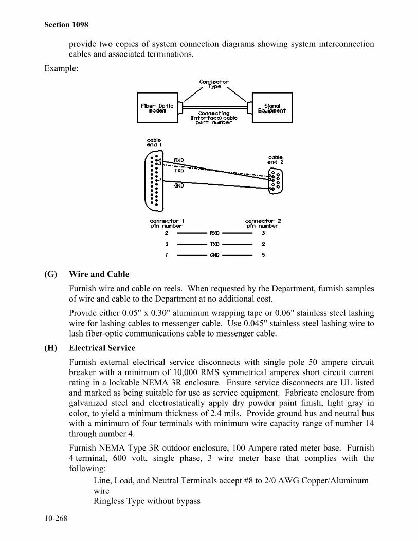
Section 1098
10-268
provide two copies of system connection diagrams showing system interconnectioncables and associated terminations.
Example:
(G) Wire and CableFurnish wire and cable on reels. When requested by the Department, furnish samplesof wire and cable to the Department at no additional cost.Provide either 0.05" x 0.30" aluminum wrapping tape or 0.06" stainless steel lashingwire for lashing cables to messenger cable. Use 0.045" stainless steel lashing wire tolash fiber-optic communications cable to messenger cable.
(H) Electrical ServiceFurnish external electrical service disconnects with single pole 50 ampere circuitbreaker with a minimum of 10,000 RMS symmetrical amperes short circuit currentrating in a lockable NEMA 3R enclosure. Ensure service disconnects are UL listedand marked as being suitable for use as service equipment. Fabricate enclosure fromgalvanized steel and electrostatically apply dry powder paint finish, light gray incolor, to yield a minimum thickness of 2.4 mils. Provide ground bus and neutral buswith a minimum of four terminals with minimum wire capacity range of number 14through number 4.Furnish NEMA Type 3R outdoor enclosure, 100 Ampere rated meter base. Furnish4 terminal, 600 volt, single phase, 3 wire meter base that complies with thefollowing:
Line, Load, and Neutral Terminals accept #8 to 2/0 AWG Copper/AluminumwireRingless Type without bypass

Section 1098
10-269
Made of galvanized steelMeets Standard UL-414Overhead or underground service entrance as specified
Provide meter bases with ampere rating of meter sockets based on sockets beingwired with minimum of 167 degrees F insulated wire. Ensure meter bases haveelectrostatically applied dry powder paint finish, light gray in color, with minimumthickness of 2.4 mils.Furnish 1" watertight hub for threaded rigid conduit with meter base.If meter base and electrical service disconnect are supplied in the same enclosure,ensure assembly is UL listed and marked as being suitable for use as serviceequipment.
(I) PaintingWhere painting of signal equipment cabinets, signal heads, signal poles, andpedestals is required, apply paint at the factory. No field painting will be allowedexcept when paint has been scratched or marred. In such cases, apply two field coatsof the same color and grade enamel as the original paint to the scratched or marredportions.
.
1098-2 BACKPLATESComply with ITE standard Vehicle Traffic Control Signal Head. Provide backplates
specific to the manufacturer of the vehicle signal heads.Fabricate backplates for vehicle signal heads from sheet aluminum a minimum of 0.05"
thick. Provide stainless steel fasteners for attachment to signal head.Provide backplates painted an alkyd urea black synthetic baking enamel with minimum
gloss reflectance that meets MIL-E-10169, Enamel Heat Resisting, Instrument Black.Provide backplates that extend a minimum of 5" from the vehicle signal head outline.
Ensure the backplate fills in the gaps between cluster-mounted vehicle signal sections (five-section vehicle signal heads). A 1/4" maximum gap between vehicle signal head andbackplate, as viewed from the front, will be allowed.1098-3 MESSENGER CABLE
Comply with ASTM A 475 for extra high strength grade wire strand, Class A zinccoating. Fabricate messenger cable from seven steel wires twisted into a single concentricstrand.
Provide universal grade strandvises used for extra high strength steel messenger cable.Provide other pole line hardware constructed of hot-dipped galvanized steel. Providemachine bolts, eyebolts, and thimbleye bolts with minimum tensile strength of 12,400 lbs.Provide galvanized nuts, washers, and thimbleyelets.

Section 1098
10-270
1098-4 CONDUIT(A) General
Use conduit bodies, boxes, and fittings that meet UL Standard 514B Conduit,Tubing, and Cable Fittings for electrical and communications installations.
(B) Conduit Types(1) Rigid Metallic Conduit
Provide rigid hot dipped galvanized steel conduit that meets UL Standard 6Electrical Rigid Metal Conduit-Steel with rigid full weight sherardized orgalvanized threaded fittings.
(2) Polyvinyl Chloride (PVC)Provide non-metallic conduit and duct including associated couplings, approvedfor above and below ground use with or without concrete encasement inaccordance with UL Standard 651A Type EB and A Rigid PVC Conduit andHDPE Conduit. Provide Schedule 40 conduit unless otherwise specified.
(3) Liquid-Tight Metallic Flexible ConduitProvide conduit that meets UL Standard 360 Liquid-Tight Flexible Steel Conduitthat is acceptable for equipment grounding in accordance with the NEC. Ensureconduit has insulated throat and malleable iron watertight fittings.
(4) High Density Polyethylene Conduit (HDPE)Provide HDPE conduit with an outer diameter to minimum wall thickness ratiothat complies with ASTM D 3035, Standard Dimension Ratio (SDR) 13.6.Provide conduit that meets UL Standard 651B Continuous Length HDPEConduit.Provide conduit that meets the following:
ASTM D 638 Tensile Strength – 3,000 psi, min; Elongation –400 percent, min
ASTM D 1238 Melt Index – 0.4 maximumASTM D 1505 Density – (0.941-0.955g/cc)ASTM D 1693 Condition B – 20 percent failure, maximumASTM D 2444 Impact – NEMA Standards Publication Number TC7ASTM D 3350 Cell Classification – 334420 or 344420
Ensure HDPE conduit is resistant to benzene, calcium chloride, ethyl alcohol,fuel oil, gasoline, lubricating oil, potassium chloride, sodium chloride, sodiumnitrate, and transformer oil, and is protected against degradation due tooxidation and general corrosion. Furnish conduit with a coefficient of frictionof 0.09 or less in accordance with Telcordia GR-356.Furnish factory lubricated, low friction, coilable, conduit constructed ofHDPE. Furnish conduit with nominal diameter as required. Provide conduitwith smooth outer wall and ribbed inner wall. Ensure conduit is capable ofbeing coiled on reels in continuous lengths, transported, stored outdoors, and

Section 1098
10-271
subsequently uncoiled for installation without affecting its properties orperformance.
(C) Conduit Plugs, Pull Line, and Tracer WireFurnish duct plugs that provide a watertight barrier when installed in conduit.Furnish duct plugs sized in accordance with conduit. Ensure duct plug providesa means to secure a pull line to the end of the plug. Provide removable and re-usable duct plugs.Furnish mechanical sealing devices that provide a watertight barrier betweenconduit and cables in conduit. Furnish mechanical sealing devices sized inaccordance with conduit and with appropriately sized holes to accommodate andseal cables. Provide removable and re-usable mechanical sealing devices.Furnish 1/2", pre-lubricated, woven polyester tape, pull line with minimum ratedtensile strength of 2,500 lb.Provide green insulated number 14 AWG, THW, stranded copper wire to serve astracer wire.Comply with Subarticle 1400-2(H) Duct and Conduit Sealer.
1098-5 JUNCTION BOXES(A) General
Comply with Article 1411-2 Electrical Junction Boxes except as follows:Provide junction box covers with standard Traffic Signal or NCDOT Fiber Opticlogos, pull slots, and stainless steel pins.Do not provide sealant compound between junction boxes and covers.
(B) Standard Sized Junction BoxesProvide standard sized junction boxes with minimum inside dimensions of16"(l) x 10"(w) x 10"(d) that meet or exceed the Tier 15 requirements of ANSI/SCTE77. Provide certification that testing methods are compliant with ANSI/SCTE 77.Vertical extensions of 6" to 12" shall be available from the junction boxmanufacturer.
(C) Oversized Heavy-Duty Junction BoxesProvide oversized heavy-duty junction boxes and covers with minimum insidedimensions of 30"(l) x 15"(w) x 24"(d) that meet or exceed the Tier 15 requirementsof ANSI/SCTE 77. Provide certification that testing methods are compliant withANSI/SCTE 77.

Section 1098
10-272
1098-6 WOOD POLESUse treated wood poles meeting the requirements of Section 1082. Unless otherwise
required by the contract, use Class 4 or better wood poles that have a minimum length of 40feet and are of a sufficient length to maintain the minimum required clearances above theroadway, obstructions, and affected railroad tracks.1098-7 GUY ASSEMBLIES
Furnish guy assemblies with anchor assemblies, guy cable, and guy cable guard.Provide anchor assemblies with all miscellaneous hardware consisting of either
expanding anchor with rod and tripleye attachment, screw anchor with extension rod andtripleye attachment, or expanding rock anchor with tripleye attachment. Ensure anchorassembly size is adequate for site conditions. Provide rods constructed of hot-dippedgalvanized steel sized according to the soil bearing conditions in the area. Provide tripleyeguy attachments constructed of hot-dipped galvanized steel. Anchor assemblies withdouble-strand eyes may be used in lieu of those with the tripleye feature when only one guycable is to be attached. Ensure anchor assemblies are 7 feet minimum in length.
For type of anchor assembly furnished, ensure the following:(A) Expanding anchor - provide steel construction with protective paint or heat shrink
of 6 mil plastic to protect metal during shipping and storage.(B) Screw anchor - provide hot-dipped galvanized steel construction.(C) Expanding rock anchors - provide malleable iron and rust-resisting paint
construction.Provide 3-bolt clamp fabricated from galvanized steel with minimum length of 5 3/4”.
Ensure clamp has parallel grooves (one on each side of bolt holes) for cable placement.Provide three 1/2” diameter galvanized bolts and nuts to tighten the clamp around themessenger cable. Ensure clamp fits 1/4” to 3/8” messenger cable.
Provide full round guy cable guards that are 8 feet in length and constructed ofultraviolet stabilized, high impact, bright yellow, high density polyethylene.
Provide guy cables consisting of messenger cable of the same size as the largest sizedmessenger cable to be guyed. Comply with Article 1098-3 Messenger Cable.1098-8 INDUCTIVE DETECTION LOOPS(A) Loop Sealant
Provide loop slot sealant that completely encapsulates loop wire when installedaccording to manufacturer’s instructions. Provide loop sealant that does not generatetemperatures greater than 220 degrees F. Ensure sealant bonds with asphalt andconcrete pavement saw slots so sealant and encapsulated loop wire do not come outof slot. Ensure sealant is self-leveling, but with sufficient viscosity to prevent exitfrom saw slot when installed along a ten percent grade.Provide sealant that protects loop wire by preventing the entrance of dirt, water,rocks, sticks, and other debris into saw slot, and is resistant to traffic, water, gasoline,chemical and chemical fumes, mild alkalis, oils, and mild acids. Ensure sealant will
Section 1098
10-273
not be affected by water and sealant does not chemically interact with pavement andloop wire insulation.Ensure loop sealant has sufficient flexibility to permit expected pavement expansionand contraction due to weather and to permit pavement movement due to trafficwithout cracking for a temperature range of -40 to 160 degrees F.Provide sealant with a usable life of at least ten minutes once mixed, when theambient temperature is 75 degrees F. Ensure sealant dries to tack free state in lessthan two hours, and does not flow within or out of saw slot after exposed surface hasbecome tack free. Tack free time will be determined by testing with a cotton balluntil no sealant adheres to cotton ball and no cotton adheres to sealant.Ensure two part sealant cures within 48 hours to attain 95 percent of publishedproperties for the cured material.Ensure one part sealant cures within 30 days to attain 95 percent of publishedproperties for the cured material.
(B) Loop WireProvide loop wire composed of 19-strand conductor insulated by a cross-linkedpolyethylene compound. Ensure insulated conductors are completely encased intubes of low density polyethylene compound. Print manufacturer’s name,manufacture year, and any applicable part number on encasing tube at intervals of2 feet or less.Provide number 14 AWG copper conductors fabricated from 19 strands that complywith ASTM B 3 before insulating. Ensure stranded conductors use either concentricor bunch stranding, and comply with circular mil area and physical requirements ofASTM B 8 or ASTM B 174 for bunch stranding.Provide insulating compound that is cross-linked thermosetting black polyethylene(ASTM D 2655). Ensure insulation is applied concentrically about conductor.Provide insulation thickness not less than 0.026" at any point and minimum averagethickness of 0.030" as measured by UL Standard 62.Ensure insulation of finished conductor will withstand application of a 60 Hertz or3000 Hertz, 7500 volt (RMS) essentially sinusoidal spark test potential as specifiedin UL Standard 83.Provide insulated conductors that are factory-installed in protective encasing tubethat comply with the following:Encasing tube fabricated of polyethylene compound conforming to ASTM D 1248for Type I, Class C, Grade E5.Minimum inside diameter of 0.150"Wall thickness of 0.040" + 0.010"Outside diameter of 0.240" + 0.010"

Section 1098
10-274
(C) ConduitComply with Article 1098-4 for non-metallic conduit.
1098-9 LOOP LEAD-IN CABLEFurnish lead-in cable with conductors of number 18 AWG fabricated from stranded
copper that complies with IMSA Specification 50-2 except as follows:Provide two pair (4 conductor) insulation pair colors: clear-brown and blue-pink.Provide four pair (8 conductor) insulation pair colors: clear-brown, blue-pink, clear with
black stripe tracer-brown with black stripe tracer, and blue with black stripe tracer-pink withblack stripe tracer. Apply continuous stripe tracer on conductor insulation with longitudinalor spiral pattern.
Ensure one spirally-wrapped Aluminum Mylar tape is applied with aluminum side out tocompletely cover conductor assembly.
Provide cable jacket formed from black polyethylene. Ensure finished jacket providesenvironmental stress resistance, outdoor weatherability, toughness, low temperatureperformance, and ultraviolet resistance.
Provide a ripcord to allow cable jacket to be opened without using a cutter.Provide length markings in sequential feet and within one percent of actual cable length.
Ensure character height of the markings is approximately 0.10".1098-10 FIBER-OPTIC CABLE(A) SMFO Communications Cable
Furnish loose tube fiber-optic cable with required fiber count that complies with RUSCFR 1755.900, single mode with dielectric central member. Use single mode fiber incable that does not exceed attenuation of 0.25 dB/km at 1550 nm and 0.35 dB/km at1310 nm. Provide cable with all fibers that are useable and with surface sufficientlyfree of imperfections and inclusions to meet optical, mechanical, and environmentalrequirements. Provide cable with minimum of one ripcord under sheath for easysheath removal and with shipping, storage, installation, and operating temperature ofat least -40 to 160 degrees F with a dual layered, UV cured acrylate fiber coatingapplied by cable manufacturer that may be stripped mechanically or chemicallywithout damaging fiber.Provide fibers inside loose buffer tube. Use doped silica core surrounded byconcentric silica cladding for each fiber. Distinguish each fiber and buffer tube fromothers by means of color coding that meets EIA/TIA-598 Color Coding of Fiber-Optic Cables. In buffer tubes containing multiple fibers, ensure colors are stableduring temperature cycling and not subject to fading, sticking, or smearing into eachother or into gel filling material. Use fillers in cable core if necessary to providea symmetrical cross-section of cable. Fill buffer tubes with non-hygroscopic, non-nutritive to fungus, electrically non-conductive, homogenous gel. Ensure gel is freefrom dirt and foreign matter, and is removable with conventional nontoxic solvents.

Section 1098
10-275
Provide a central member consisting of a dielectric glass reinforced plastic rod.Apply binders with sufficient tension to secure buffer tubes and binders to the centralmember without crushing buffer tubes. Ensure that binders are non-hygroscopic,non-wicking (or rendered so by the flooding compound), and dielectric with lowshrinkage.Provide cable that has cable core interstices filled with super-absorbent, water-blocking compound that is non-conductive and homogenous. Ensure compound isfree from dirt and foreign matter, and is removable with conventional nontoxicsolvents.Provide cable with high tensile strength aramid yarns or fiberglass yarns that arehelically stranded evenly around cable core.Provide cable jacket of consistent thickness that is free of holes, splits, and blisters,and contains no metal elements. Provide outer jacket of medium densitypolyethylene with minimum nominal sheath thickness of 0.050 inch. Ensurepolyethylene contains carbon black for ultraviolet light protection and does notpromote fungus growth.Provide length markings in sequential feet and within one percent of actual cablelength. Ensure character height of the markings is approximately 0.10".
(B) Drop CableFurnish drop cable assemblies to provide communications links between spliceenclosures and transceivers through interconnect centers. Furnish drop cableassemblies containing a minimum of six individual fibers.Furnish drop cable assemblies that comply with RUS-CFR 1755.900. Ensure dropcable assemblies have the same operating characteristics as the SMFO cable it is tobe coupled with.On one end of cable assemblies, furnish six ST-PC connectors for termination onconnector panel in equipment cabinet. Provide either factory assembled drop cableswith ST-PC connectors or field installed connectors.Ensure attenuation of drop cable at 1310 nm does not exceed 0.5 dB/km. Ensureattenuation loss for complete drop cable assembly does not exceed a mean value of1.5 dB.Provide length markings in sequential feet and within one percent of actual cablelength. Ensure character height of markings is approximately 0.10".
(C) Communications Cable Identification MarkersFurnish yellow communications cable identification markers that are resistant tofading when exposed to UV sources and changes in weather. Use markers designedto coil around fiber-optic cable that do not slide or move along the surface of thecable once installed. Ensure exposure to UV light and weather does not affect themarkers natural coiling effect or deteriorate performance. Provide communicationscable wraps that permit writing with an indelible marking pen and contain thefollowing text in black:
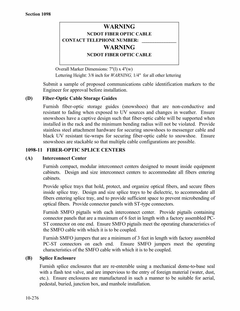
Section 1098
10-276
WARNINGNCDOT FIBER OPTIC CABLE
CONTACT TELEPHONE NUMBER: _______________WARNING
NCDOT FIBER OPTIC CABLE
Overall Marker Dimensions: 7"(l) x 4"(w)Lettering Height: 3/8 inch for WARNING, 1/4" for all other lettering
Submit a sample of proposed communications cable identification markers to theEngineer for approval before installation.
(D) Fiber-Optic Cable Storage GuidesFurnish fiber-optic storage guides (snowshoes) that are non-conductive andresistant to fading when exposed to UV sources and changes in weather. Ensuresnowshoes have a captive design such that fiber-optic cable will be supported wheninstalled in the rack and the minimum bending radius will not be violated. Providestainless steel attachment hardware for securing snowshoes to messenger cable andblack UV resistant tie-wraps for securing fiber-optic cable to snowshoe. Ensuresnowshoes are stackable so that multiple cable configurations are possible.
1098-11 FIBER-OPTIC SPLICE CENTERS(A) Interconnect Center
Furnish compact, modular interconnect centers designed to mount inside equipmentcabinets. Design and size interconnect centers to accommodate all fibers enteringcabinets.Provide splice trays that hold, protect, and organize optical fibers, and secure fibersinside splice tray. Design and size splice trays to be dielectric, to accommodate allfibers entering splice tray, and to provide sufficient space to prevent microbending ofoptical fibers. Provide connector panels with ST-type connectors.Furnish SMFO pigtails with each interconnect center. Provide pigtails containingconnector panels that are a maximum of 6 feet in length with a factory assembled PC-ST connector on one end. Ensure SMFO pigtails meet the operating characteristics ofthe SMFO cable with which it is to be coupled.Furnish SMFO jumpers that are a minimum of 3 feet in length with factory assembledPC-ST connectors on each end. Ensure SMFO jumpers meet the operatingcharacteristics of the SMFO cable with which it is to be coupled.
(B) Splice EnclosureFurnish splice enclosures that are re-enterable using a mechanical dome-to-base sealwith a flash test valve, and are impervious to the entry of foreign material (water, dust,etc.). Ensure enclosures are manufactured in such a manner to be suitable for aerial,pedestal, buried, junction box, and manhole installation.

Section 1098
10-277
Provide enclosures with a minimum of one over-sized oval port that will accept twocables and with a minimum of four round ports (for single cables) that willaccommodate all cables entering enclosure. Provide heat shrink cable shields withenclosure to ensure weather tight seal where each cable enters enclosure.Within enclosures, provide enough hinged mountable splice trays to store the number ofsplices required, plus the capacity to house six additional splices. Provide a fibercontainment basket for storage of loose buffer tubes expressed through the enclosure.Ensure enclosures allow sufficient space to prevent microbending of buffer tubes whencoiled.Provide splice trays that hold, protect, and organize optical fibers, and secure fibersinside splice tray. Provide splice trays that are dielectric.
1098-12 FIBER-OPTIC TRANSCEIVERSFurnish shelf-mounted, modular, single mode fiber-optic transceivers that transmit and
receive optical signals over a fiber-optic communications medium of two fibers and interfacewith equipment cabinets (signal controller, dynamic message signs, etc.). Ensure transceiversare asynchronous in operation. Ensure transceivers are capable of operating up to 5 mileswithout boosting signal and without distortion. Ensure transceivers are switch selectable foreither local or master operation.
Do not provide transceivers internal to system equipment. Provide identical transceivers atall locations capable of being interchanged throughout system.
Provide LEDs on the front panel of transceivers for power, and transmitting and receivingindications. Comply with the following:
Input Power: 115 VACMinimum Loss Budget: 12 dB with corresponding receiverOperating Wavelength: 1310 or 1550 nm
Optical Connector: STSignal Connector: Female Plug TypeTemperature Range: 0 to 150 degrees F
Ensure modems operate in one of the following topologies:Drop and Repeat Transceivers: Furnish transceivers that transmit and receivedata in drop-and-repeat poll-response data network mode with EIA/TIA-232,EIA/TIA-422, and EIA/TIA-485 protocols.Self-Healing Ring Transceivers: Furnish transceivers that transmit and receivedata in a drop-and-insert poll-response data network mode with EIA/TIA-232,EIA/TIA-422, and EIA/TIA-485 protocols. Ensure transceiver operates in a Self-Healing Ring Network Architecture.
1098-13 DELINEATOR MARKERSFurnish tubular delineator markers, approximately 6 feet long, and constructed of
Type III, high density polyethylene material. Provide delineator assemblies that areultraviolet stabilized to help prevent components from color fading, warping, absorbingwater, and deterioration with prolonged exposure to the elements. Provide delineators
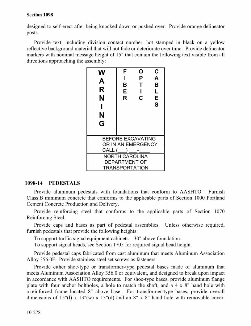
Section 1098
10-278
designed to self-erect after being knocked down or pushed over. Provide orange delineatorposts.
Provide text, including division contact number, hot stamped in black on a yellowreflective background material that will not fade or deteriorate over time. Provide delineatormarkers with nominal message height of 15" that contain the following text visible from alldirections approaching the assembly:
WARNING
FIBER
OPTIC
CABLES
BEFORE EXCAVATINGOR IN AN EMERGENCYCALL (___) ___-____NORTH CAROLINADEPARTMENT OF
TRANSPORTATION
1098-14 PEDESTALSProvide aluminum pedestals with foundations that conform to AASHTO. Furnish
Class B minimum concrete that conforms to the applicable parts of Section 1000 PortlandCement Concrete Production and Delivery.
Provide reinforcing steel that conforms to the applicable parts of Section 1070Reinforcing Steel.
Provide caps and bases as part of pedestal assemblies. Unless otherwise required,furnish pedestals that provide the following heights:
To support traffic signal equipment cabinets – 30" above foundation.To support signal heads, see Section 1705 for required signal head height.Provide pedestal caps fabricated from cast aluminum that meets Aluminum Association
Alloy 356.0F. Provide stainless steel set screws as fasteners.Provide either shoe-type or transformer-type pedestal bases made of aluminum that
meets Aluminum Association Alloy 356.0 or equivalent, and designed to break upon impactin accordance with AASHTO requirements. For shoe-type bases, provide aluminum flangeplate with four anchor boltholes, a hole to match the shaft, and a 4 x 8" hand hole witha reinforced frame located 8" above base. For transformer-type bases, provide overalldimensions of 15"(l) x 13"(w) x 13"(d) and an 8" x 8" hand hole with removable cover.

Section 1098
10-279
Ensure bases are continuously welded to shafts or threaded to receive shafts. For use ingrounding, provide a 1/2" minimum diameter, coarse thread stud located inside base at thehandhold and oriented for easy access.
For each pedestal, provide four bolts with outside diameter of 3/4" and length of 18"each with leveling nut and washer. Ensure anchor bolts are hot-dipped galvanized inaccordance with ASTM A 153 with completely galvanized nuts and washers.1098-15 SIGNAL CABINET FOUNDATIONS
Provide foundations with a minimum pad area that extends 24" from front and back ofcabinet and 3" from sides of cabinet.
Furnish cabinet foundations with chamfered top edges. Provide minimum Class Bconcrete.
Provide preformed cabinet pad foundations with 7"(l) x 18"(w) minimum opening forthe entrance of conduits. Ensure that no more than four 3/4" holes are cast or drilled in eachpad.1098-16 CABINET BASE ADAPTER/EXTENDER
Fabricate base adapters and extenders from the same materials and with the same finishas cabinet housing. Fabricate base adapter and extender in the same manner as controllercabinets, meeting all applicable specifications called for in Section 7.5 of CALTRANSTEES (11/19/99). Provide base adapters and extenders a minimum height of 12".1098-17 BEACON CONTROLLER ASSEMBLIES(A) General
Furnish all cabinets with a solid state flasher that meets NEMA TS-2-1998.Encapsulate flasher components as necessary. Connect flasher to provide beaconoperation as specified.Submit drawings showing dimensions, location of required equipment andmechanisms, cabinet electrical diagrams, part numbers and descriptions of requiredequipment and accessories to the Engineer. Provide certification to the Engineerthat materials used in cabinet construction meets these Specifications.Furnish unpainted, natural, aluminum cabinet shells that comply with Section 7 ofNEMA TS-2-1998. Ensure all non-aluminum hardware on cabinet is stainless steelor Department approved non-corrosive alternate. Provide roof with slope fromfront to back at a minimum ratio of 1" drop per 2 feet. Ensure each exterior cabinetplane surface is constructed of a single sheet of seamless aluminum. Ensure allcomponents are arranged for easy access during servicing. When modular inconstruction, provide guides and positive connection devices to ensure proper pinalignment and connection.Connect metal oxide varister, type V150LA20, between each field terminal andground bus.Provide beacon controller assemblies equipped with terminal blocks (strips) fortermination of all field conductors and all internal wires and harness conductors.Terminate all wires at terminals. Ensure all field terminals are readily accessiblewithout removing equipment and located conveniently to wires, cables, and

Section 1098
10-280
harnesses to be connected. Ensure terminals are not located on under side ofshelves or at other places where they are not readily visible or where they maypresent a hazard to personnel who might inadvertently touch them. Provideterminal blocks made of electrical grade thermoplastic or thermosetting plastic.Ensure each terminal block is of closed back design and has recessed-screwterminals with molded barriers between terminals. Ensure each terminal consists oftwo terminal screws with removable shorting bar between them. Ensure eachterminal block is labeled with a block designation and each terminal is labeled witha number. Ensure all terminal functions are labeled on terminal blocks. Providelabels that are visible when terminal block is fully wired. Show labels on cabinetwiring diagrams. Ensure terminals serving similar functions are grouped together.Connect each conductor, including unused conductors, within or entering cabinet toa terminal using crimped spade lugs. Place no more than two conductors on anysingle terminal screw. Terminations to back panel may be soldered. Do not usequick connectors or barrel connectors. Make all connections at terminals. Do notmake in-line splices.Ensure outgoing circuits have same polarity as line side of power supply. Ensurecommon return has same polarity as grounded conductor (neutral) of power supply.Neatly package all wiring. Dress harnesses by lacing, braiding, or tying with nylontie wraps at closely spaced intervals. Attach wires, cables, or harnesses to cabinetwalls for support or to prevent undue wear or flexing. Use nylon tie straps or metalclamps with rubber or neoprene insulators. Screw these attachment devices tocabinet. Do not use stick-on clamps or straps.Tag AC+, AC-, chassis ground, and flasher circuit conductors with non-fading,permanent sleeve labels at conductor ends at terminals or use color-coded wire.Ensure sleeve labels tightly grip conductors. Alternatively, use hot stamped labelson internal conductor insulation at intervals of no greater than 4". Ensure labellegends are permanent.Ensure all jumpers are wire conductors or metal plates. Do not use printed circuitback panels or back panels using wire tracks as jumpers.Lay out all equipment and components for ease of use and servicing. Ensureequipment controls can be viewed and operated without moving or removing anyequipment. Ensure there is access to equipment or components for servicingwithout removing any other equipment or components. Removal of equipment isacceptable to access fan or thermostat. Ensure equipment can be removed usingonly simple hand tools. Ensure layout of equipment and terminals within thevarious cabinets furnished is identical from cabinet to cabinet, unless otherwiseapproved.Mount equipment using harnesses with suitable multipin (or similar) connectors.Design or key all equipment to make it physically impossible to connect unit towrong connector. Ensure that functionally equivalent equipment is electrically andmechanically interchangeable.Equip vents with standard-size, replaceable filters or, if located where they caneasily be cleaned, permanent filters.
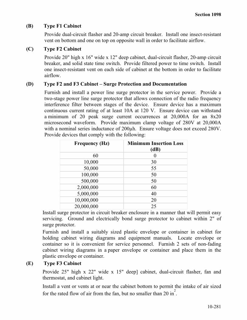
Section 1098
10-281
(B) Type F1 CabinetProvide dual-circuit flasher and 20-amp circuit breaker. Install one insect-resistantvent on bottom and one on top on opposite wall in order to facilitate airflow.
(C) Type F2 CabinetProvide 20" high x 16" wide x 12" deep cabinet, dual-circuit flasher, 20-amp circuitbreaker, and solid state time switch. Provide filtered power to time switch. Installone insect-resistant vent on each side of cabinet at the bottom in order to facilitateairflow.
(D) Type F2 and F3 Cabinet – Surge Protection and DocumentationFurnish and install a power line surge protector in the service power. Provide atwo-stage power line surge protector that allows connection of the radio frequencyinterference filter between stages of the device. Ensure device has a maximumcontinuous current rating of at least 10A at 120 V. Ensure device can withstanda minimum of 20 peak surge current occurrences at 20,000A for an 8x20microsecond waveform. Provide maximum clamp voltage of 280V at 20,000Awith a nominal series inductance of 200µh. Ensure voltage does not exceed 280V.Provide devices that comply with the following:
Frequency (Hz) Minimum Insertion Loss(dB)
60 010,000 3050,000 55
100,000 50500,000 50
2,000,000 605,000,000 40
10,000,000 2020,000,000 25
Install surge protector in circuit breaker enclosure in a manner that will permit easyservicing. Ground and electrically bond surge protector to cabinet within 2" ofsurge protector.Furnish and install a suitably sized plastic envelope or container in cabinet forholding cabinet wiring diagrams and equipment manuals. Locate envelope orcontainer so it is convenient for service personnel. Furnish 2 sets of non-fadingcabinet wiring diagrams in a paper envelope or container and place them in theplastic envelope or container.
(E) Type F3 CabinetProvide 25" high x 22" wide x 15" deep] cabinet, dual-circuit flasher, fan andthermostat, and cabinet light.Install a vent or vents at or near the cabinet bottom to permit the intake of air sizedfor the rated flow of air from the fan, but no smaller than 20 in
2.

Section 1098
10-282
Equip cabinet with two NEMA standard circuit breakers (20A & 15A) installed toensure personnel servicing the cabinet, including rear of back panel, cannotinadvertently be exposed to a hazard. Install a terminal block that will accommodateservice wire as large as number 4 AWG, and connect it to the circuit breaker. Installcircuit breakers in addition to any fuses that are a part of the individual controlequipment components. Wire cabinet light and thermostatically-controlled fan tothe 15A circuit breaker.Ensure cabinet has sufficient electrical and electronic noise suppression to enable allequipment in it to function properly. In addition, equip cabinet with a radiointerference filter connected between stages of the power line surge protector.Ensure filter minimizes interference generated in the cabinet in both broadcast andaircraft frequencies. Use filter that provides attenuation of at least 50 decibels overa frequency range of 200 kilohertz to 75 megahertz. Ensure filter is hermeticallysealed in an insulated metal or plastic case. Provide filter designed to operate ina 120-volt, 60 Hertz, single-phase circuit with currents of 15 amperes or more, suchas HESCO LF35, or equivalent.Provide filtered power to detector panel.