Embed Size (px)
Citation preview

PROJECT SPECIFICATION 16/05/2016
1 DIVISION 08 - OPENINGS.doc Industrial Buildings & Logistics Solutions | [email protected] | www.ibls.gr
DIVISION 08 – OPENINGS
PHARMACEUTICAL & DISTRIBUTION WAREHOUSE IN RIYADH
0 16-May-16 Issued for Construction FC PV IM
REV DATE DESCRIPTION OF REVISION Author D.M P.M F1 PROJECT No.: 100
DOC. DESCRIPTION DIVISION 08
OPENINGS
Sheet: 1 of 49
PROJECT SPECIFICATION 16/05/2016
2 DIVISION 08 - OPENINGS.doc Industrial Buildings & Logistics Solutions | [email protected] | www.ibls.gr
Table of Contents
PHARMACEUTICAL & DISTRIBUTION WAREHOUSE IN RIYADH 1
1. DIVISION 08 – OPENINGS 4
1.1 ATTACHED DRAWINGS 4
1.2 REFERENCES 4
1.3 SYSTEM DESCRIPTION 4 1.3.1 Description of Work 4 1.3.2 Summary 4
2. SPECIFICATIONS SECTIONS 5 D10.05.00 COMMON WORK 5
D08.11. Metal Doors and Frames 5
D08.11.19.Stainless-Steel Doors and Frames 5 PART 1 – GENERAL 5 PART 2 – PRODUCTS 7 D08.11.19.01c.Fire Escapes Exits 7 PART 3 – EXECUTION 8
D08.13. Metal Doors 8
D08.13.73.Sliding Metal Doors 8 PART 1 – GENERAL 8 PART 2 – PRODUCTS 9 D08.13.73.01c.Cold Storage Expressway Doors (Rapid Doors) 9 D08.13.73.02c Expressway Doors (Rapid Doors) 10 PART 3 – EXECUTION 11
D08.31. Access Doors and Panels 12
D08.31.13.Access Doors and Frames 12 PART 1 – GENERAL 12 PART 2 – PRODUCTS 13 D08.31.13.01c.Single Sheet Metal Access Doors and Frames 13 D08.31.13.02c.Double Sheet Metal Access Doors and Frames 15 PART 3 – EXECUTION 16
D08.33. Coiling Doors and Grilles 17
D08.33.23c Overhead Coiling Fire Doors 17 PART 1 – GENERAL 17 PART 2 – PRODUCTS 19 D08.33.23c.01c Fire Resistant Rolls 19 PART 3 – EXECUTION 21
D08.34. Special Function Doors 22
D08.34.13 Cold Storage Doors 22 PART 1 – GENERAL 22 PART 2 – PRODUCTS 22 D08.34.13.01c.Cold Storage Sliding Doors 22

PROJECT SPECIFICATION 16/05/2016
3 DIVISION 08 - OPENINGS.doc Industrial Buildings & Logistics Solutions | [email protected] | www.ibls.gr
D08.34.13.02c.Cold Storage Fire Escape Exits 24 D08.34.13.03c.Cold Storage Fire Escape Exits With ACS Operation 24 D08.34.13.04c.Cold Storage Fire Proofed Doors 25 PART 3 – EXECUTION 26
D08.34.53 Security Doors and Frames 27 PART 1 – GENERAL 27 PART 2 – PRODUCTS 27 D08.34.53.01c Fire Proofed Doors 27 D08.34.53.02c.Fire Proofed Doors (Double sheet) 28 D08.34.53.03c.Fire Proofed Doors with ACS Operation 28 PART 3 – EXECUTION 28
D08.36. Panel Doors 29
D08.36.13 Sectional Doors 29 PART 1 – GENERAL 29 PART 2 – PRODUCTS 31 D08.36.13.01c Industrial Doors 31 PART 3 – EXECUTION 33
D08.71. Door Hardware 35
D08.71.53.Security Door Hardware 35 PART 1 – GENERAL 35 PART 2 – PRODUCTS 38 D08.71.53.01c.Security Door Hardware 38 PART 3 – EXECUTION 47

PROJECT SPECIFICATION 16/05/2016
4 DIVISION 08 - OPENINGS.doc Industrial Buildings & Logistics Solutions | [email protected] | www.ibls.gr
1. DIVISION 08 – OPENINGS
1.1 ATTACHED DRAWINGS
TBD
1.2 REFERENCES
With regard to Architectural Systems, the study has been conducted according to the following Standards, Codes, Regulations and Guidelines:
Modon - Guidelines and Building Requirements for Factories and Services Facilities
Saudi Building Code SBC 201 Architectural The International Building Code (IBC) The National Fire Protection Association (NFPA) Codes and Standards All Standards referenced in the Specifications below.
1.3 SYSTEM DESCRIPTION
1.3.1 Description of Work
This specification covers the furnishing and installation of material for aluminum/steel doors and frames. Products shall be as follows or as directed by the Owner. Installation procedures shall be in accordance with the products manufacturer’s recommendations. Demolition and removal of materials shall be as required to support the work.
1.3.2 Summary
This section includes standard/custom hollow metal doors and frames.
Each door and its frame is delivered individually crated for protection from damage in cardboard containers, clearly marked with project information, door/window location, specific reference number as shown on drawings, and shipping information.
Each crate contains all fasteners necessary for installation as well as complete installation instructions.
Doors are stored in the original container out of inclement weather for protection against the elements until their installation; during which they are handled pursuant to the manufacturer's recommendations.

PROJECT SPECIFICATION 16/05/2016
5 DIVISION 08 - OPENINGS.doc Industrial Buildings & Logistics Solutions | [email protected] | www.ibls.gr
2. SPECIFICATIONS SECTIONS
D08.00.00 OPENINGS
D10.05.00 COMMON WORK
D08.11. Metal Doors and Frames
D08.11.19.Stainless-Steel Doors and Frames
PART 1 – GENERAL 1) Description of Work
1. This specification covers the furnishing and installation of material for steel doors and frames.
Products shall be as follows or as directed by the Owner. Installation procedures shall be in accordance with the products manufacturer’s recommendations. Demolition and removal of materials shall be as required to support the work.
2) Summary
1. Section Includes:
a. Standard hollow metal doors and frames.
b. Custom hollow metal doors and frames.
3) Definitions
1. Minimum Thickness: Minimum thickness of base metal without coatings.
2. Standard Hollow Metal Work: Hollow metal work fabricated according to ANSI/SDI A250.8.
3. Custom Hollow Metal Work: Hollow metal work fabricated according to ANSI/NAAMMHMMA 861.
4) Submittals
1. Product Data: For each type of product indicated.
2. Shop Drawings: Include elevations, door edge details, frame profiles, metal thicknesses, preparations for hardware, and other details.
3. Samples for Verification: For each type of exposed finish required.
4. Schedule: Prepared by or under the supervision of supplier, using same reference numbers for details and openings as those on Drawings.
PROJECT SPECIFICATION 16/05/2016
6 DIVISION 08 - OPENINGS.doc Industrial Buildings & Logistics Solutions | [email protected] | www.ibls.gr
5. Oversize Construction Certification: For assemblies required to be fire rated and exceeding limitations of labeled assemblies.
6. Product Test Reports: Based on evaluation of comprehensive tests performed by a qualified testing agency, for each type of hollow metal door and frame assembly.
5) Quality Assurance
1. Fire-Rated Door Assemblies: Assemblies complying with NFPA 80 that are listed and labeled by a qualified testing agency, for fire-protection ratings indicated, based on testing at positive pressure OR as close to neutral pressure as possible, as directed, according to NFPA 252 OR UBC Standard 7-2, as directed, or UL 10BOR UL 10C, as directed.
a. Oversize Fire-Rated Door Assemblies: For units exceeding sizes of tested assemblies, provide certification by a qualified testing agency that doors comply with standard construction requirements for tested and labeled fire-rated door assemblies except for size.
b. Temperature-Rise Limit: Where indicated OR At vertical exit enclosures and exit passageways, as directed, provide doors that have a maximum transmitted temperature end point of not more than 450 deg F (250 deg C) above ambient after 30 minutes of standard fire-test exposure.
2. Fire-Rated, Borrowed-Light Frame Assemblies: Assemblies complying with NFPA 80 that are listed and labeled, by a testing and inspecting agency acceptable to authorities having jurisdiction, for fire-protection ratings indicated, based on testing according to NFPA 257 or UL 9 OR UBC Standard 7-4, as directed. Label each individual glazed lite.
3. Smoke-Control Door Assemblies: Comply with NFPA 105 or UL 1784 OR UBC Standard 7-2, as directed.
6) Delivery, Storage, And Handling
1. Deliver hollow metal work palletized, wrapped, or crated to provide protection during transit and Project-site storage. Do not use nonvented plastic.
a. Provide additional protection to prevent damage to finish of factory-finished units.
2. Deliver welded frames with two removable spreader bars across bottom of frames, tack welded to jambs and mullions.
3. Store hollow metal work under cover at Project site. Place in stacks of five units maximum in a vertical position with heads up, spaced by blocking, on minimum 4-inch- (102-mm-) high wood blocking. Do not store in a manner that traps excess humidity.
a. Provide minimum 1/4-inch (6-mm) space between each stacked door to permit air circulation.
PROJECT SPECIFICATION 16/05/2016
7 DIVISION 08 - OPENINGS.doc Industrial Buildings & Logistics Solutions | [email protected] | www.ibls.gr
PART 2 – PRODUCTS
D08.11.19.01c.Fire Escapes Exits
1) Item Description
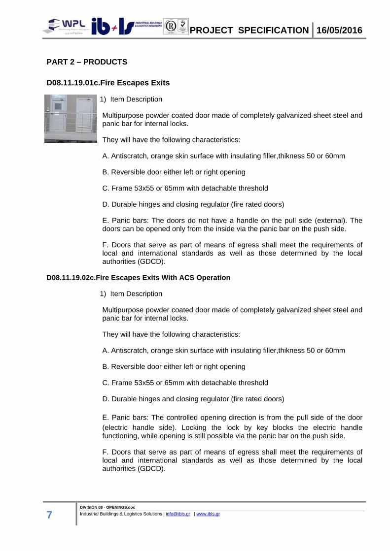
Multipurpose powder coated door made of completely galvanized sheet steel and panic bar for internal locks.
They will have the following characteristics:
A. Antiscratch, orange skin surface with insulating filler,thikness 50 or 60mm
B. Reversible door either left or right opening
C. Frame 53x55 or 65mm with detachable threshold
D. Durable hinges and closing regulator (fire rated doors)
E. Panic bars: The doors do not have a handle on the pull side (external). The doors can be opened only from the inside via the panic bar on the push side.
F. Doors that serve as part of means of egress shall meet the requirements of local and international standards as well as those determined by the local authorities (GDCD).
D08.11.19.02c.Fire Escapes Exits With ACS Operation
1) Item Description
Multipurpose powder coated door made of completely galvanized sheet steel and panic bar for internal locks.
They will have the following characteristics:
A. Antiscratch, orange skin surface with insulating filler,thikness 50 or 60mm
B. Reversible door either left or right opening
C. Frame 53x55 or 65mm with detachable threshold
D. Durable hinges and closing regulator (fire rated doors)
E. Panic bars: The controlled opening direction is from the pull side of the door
(electric handle side). Locking the lock by key blocks the electric handle functioning, while opening is still possible via the panic bar on the push side.
F. Doors that serve as part of means of egress shall meet the requirements of local and international standards as well as those determined by the local authorities (GDCD).
PROJECT SPECIFICATION 16/05/2016
8 DIVISION 08 - OPENINGS.doc Industrial Buildings & Logistics Solutions | [email protected] | www.ibls.gr
G. Card-based Access Control System (ACS), as specified in D28.13.13.Access
Control Global Applications, D08.71.53.01c.Security Door Hardware and according to attached drawings.
PART 3 – EXECUTION
1) Standard packaging
Single door wrapped into stretchable polyethylene (PE) film
2) Installation methods
For mortar fixing, appropriate cuts will need to be created in the walls (section 80 x 200 mm). The anchors should be bent and blocked inside the wall. For fire sealing purposes and mechanical hold, the space between the doorframe and the masonry should always be filled with concrete mortar.
D08.13. Metal Doors
D08.13.73.Sliding Metal Doors
PART 1 – GENERAL
1) Description Of Work
1. This specification covers the furnishing and installation of material for folding doors. Products shall be as follows or as directed by the Owner. Installation procedures shall be in accordance with the products manufacturer’s recommendations. Demolition and removal of materials shall be as required to support the work.
2) Summary
1. Section Includes:
a. Accordion folding doors.
b. Panel folding doors.
c. Bifold doors.
d. Bifold mirror doors.
e. Fire-rated folding doors.
3) Submittals
1. Product Data: For each type of product indicated.
PROJECT SPECIFICATION 16/05/2016
9 DIVISION 08 - OPENINGS.doc Industrial Buildings & Logistics Solutions | [email protected] | www.ibls.gr
2. Shop Drawings: Include plans, elevations, sections, details, attachments to other work.
a. Fire-Release System: Describe system, including testing and resetting instructions. b. Wiring Diagrams: For power, signal, and control wiring.
3. Samples: For each exposed product and for each color and texture specified.
4. Product Schedule: For folding doors. Use same designations indicated on Drawings.
5. Product certificates.
6. Maintenance data.
4) Quality Assurance
1. Surface-Burning Characteristics: As determined by testing identical products according to ASTM E 84 by a qualified testing agency. Identify products with appropriate markings of applicable testing agency.
a. Flame-Spread Index: 25 or less. b. Smoke-Developed Index: 50 OR 450, as directed, or less.
2. Fire-Rated Folding Door Assemblies: Assemblies complying with NFPA 80 that are listed and labeled by a qualified testing agency, for fire-protection ratings indicated, based on testing according to NFPA 252 OR UBC Standard 7-2 OR UL 10B, as directed.
a.Oversize Fire-Rated Folding Doors: For units exceeding sizes of tested assemblies, provide certification by a qualified testing agency that doors comply with standard construction requirements for tested and labeled fire-rated door assemblies except for size.
5) Project Conditions
a. Environmental Limitations: Do not deliver or install folding doors until spaces are enclosed and weather tight, wet work in spaces is complete and dry, and temporary HVAC system is operating and maintaining ambient temperature and humidity conditions at occupancy levels during the remainder of the construction period.
b. Field Measurements: Verify actual dimensions of openings by field measurements before fabrication
PART 2 – PRODUCTS
D08.13.73.01c.Cold Storage Expressway Doors (Rapid Doors)
1) Item Description
PROJECT SPECIFICATION 16/05/2016
10 DIVISION 08 - OPENINGS.doc Industrial Buildings & Logistics Solutions | [email protected] | www.ibls.gr
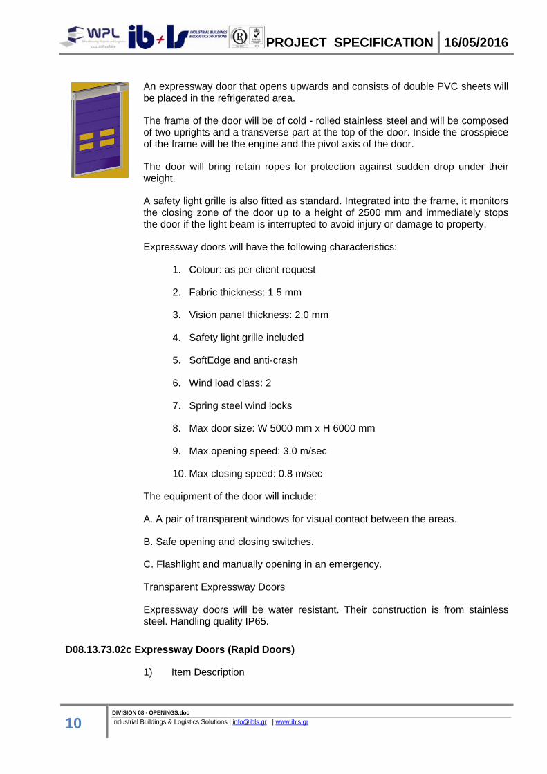
An expressway door that opens upwards and consists of double PVC sheets will be placed in the refrigerated area.
The frame of the door will be of cold - rolled stainless steel and will be composed of two uprights and a transverse part at the top of the door. Inside the crosspiece of the frame will be the engine and the pivot axis of the door.
The door will bring retain ropes for protection against sudden drop under their weight.
A safety light grille is also fitted as standard. Integrated into the frame, it monitors the closing zone of the door up to a height of 2500 mm and immediately stops the door if the light beam is interrupted to avoid injury or damage to property.
Expressway doors will have the following characteristics:
1. Colour: as per client request
2. Fabric thickness: 1.5 mm
3. Vision panel thickness: 2.0 mm
4. Safety light grille included
5. SoftEdge and anti-crash
6. Wind load class: 2
7. Spring steel wind locks
8. Max door size: W 5000 mm x H 6000 mm
9. Max opening speed: 3.0 m/sec
10. Max closing speed: 0.8 m/sec
The equipment of the door will include:
A. A pair of transparent windows for visual contact between the areas.
B. Safe opening and closing switches.
C. Flashlight and manually opening in an emergency.
Transparent Expressway Doors
Expressway doors will be water resistant. Their construction is from stainless steel. Handling quality IP65.
D08.13.73.02c Expressway Doors (Rapid Doors)
1) Item Description

PROJECT SPECIFICATION 16/05/2016
11 DIVISION 08 - OPENINGS.doc Industrial Buildings & Logistics Solutions | [email protected] | www.ibls.gr
External doors are driven into more frequently than internal doors and so this door is equipped with spring steel wind locks that provide necessary curtain stability for a speed of up to 3.0 m/sec.
Innovative SoftEdge door technology prevents damages and resulting downtimes of the door system. If there is a crash and the bottom profile is pushed out of the side guides, the radio crash switch transmits a signal to the control and the door is stopped immediately. Thanks to this technology, this door can be operated for up to 3 years without the need for maintenance, regardless of the number of door cycles.
A safety light grille is also fitted as standard. Integrated into the frame, it monitors the closing zone of the door up to a height of 2500 mm and immediately stops the door if the light beam is interrupted to avoid injury or damage to property.
They will have the following characteristics:
1. Use: Internal and external
2. Available in 5 RAL colours
3. Fabric thickness: 1.5 mm
4. Vision panel thickness: 2.0 mm
5. Safety light grille included
6. SoftEdge and anti-crash
7. Wind load class: 2
8. Spring steel wind locks
9. Max door size: W 5000 mm x H 6000 mm
10. Max opening speed: 3.0 m/sec
11. Max closing speed: 0.8 m/sec
PART 3 – EXECUTION
1) Preparation
1. For folding doors supported by or anchored to permanent construction, advise installers of specific requirements for placement of anchorage devices. Furnish installers of other work with templates and drawings showing locations of anchorage devices and similar items.
2. In path of fire-rated folding doors, level floor with header to tolerance of plus or minus 1/16 inch (1.6 mm) across opening; grind or fill floor as necessary.
2) Installation

PROJECT SPECIFICATION 16/05/2016
12 DIVISION 08 - OPENINGS.doc Industrial Buildings & Logistics Solutions | [email protected] | www.ibls.gr
1. General: Install folding doors complying with manufacturer's written installation instructions. Install track in one piece.
a. Comply with NFPA 80 for installing fire-rated folding doors.
2. Standard Floor Clearances: 1/4 to 3/4 inch (6.4 to 19 mm) maximum (above floor finish).
a. Comply with NFPA 80 for clearances required for fire-rated folding doors.
3. Coordinate provisions for electrical service, sensing devices, and final connections for fire-rated folding doors.
3) Adjusting
1. Adjust units as necessary to ensure smooth, quiet operation without warping or binding. Adjust hardware to function smoothly. Confirm that latches engage accurately and securely without forcing or binding.
a. Fire-Rated Folding Doors: Verify that all operations are functional and comply with requirements of authorities having jurisdiction.
2. Pocket Doors: Adjust to operate smoothly and easily, without binding or warping. Adjust hardware to function smoothly. Confirm that latches and locks engage accurately and securely without forcing or binding.
4) Demonstration
1. Engage a factory-authorized service representative to train Owner's maintenance personnel to adjust, operate, and maintain fire-rated folding doors.
D08.31. Access Doors and Panels
D08.31.13.Access Doors and Frames
PART 1 – GENERAL 1) Description of Work 1. This specification covers the furnishing and installation of material for access doors and frames. Products shall be as follows or as directed by the Owner. Installation procedures shall be in accordance with the products manufacturer’s recommendations. Demolition and removal of materials shall be as required to support the work. These doors will be installed at the Technical Spaces Building and the Guard Houses. 2) Summary 1. This Section includes the following: a. Access doors and frames for walls and ceilings. b. Floor access doors and frames.

PROJECT SPECIFICATION 16/05/2016
13 DIVISION 08 - OPENINGS.doc Industrial Buildings & Logistics Solutions | [email protected] | www.ibls.gr
3) Submittals 1. Product Data: For each type of access door and frame indicated. 2. Shop Drawings: Include plans, elevations, sections, details, and attachments to other work. 3. Samples: For each door face material in specified finish. 4. Schedule: Types, locations, sizes, latching or locking provisions, and other data pertinent to installation. 4) Quality Assurance 1. Fire-Rated Access Doors and Frames: Units complying with NFPA 80 that are identical to access door and frame assemblies tested for fire-test-response characteristics per the following test method and that are listed and labeled by UL or another testing and inspecting agency acceptable to authorities having jurisdiction: a. NFPA 252 or UL 10B for vertical access doors and frames. b. ASTM E 119 or UL 263 for horizontal access doors and frames.
PART 2 – PRODUCTS
D08.31.13.01c.Single Sheet Metal Access Doors and Frames
1) Item Description
1. Solid design and manufacture
2. Fully galvanized door, including the “hidden” parts
3. Made of “Sendzimir” process hot-galvanized sheet metal
4. Corrosion protection also provided along cut edges of the metal sheets
5. Painted with epoxy-polyester thermoset powders in a 180 degrees (Celsius) oven
6. Substantial paint layer (70 microns plus)
7. Optimal corrosion resistance demonstrated by 500 hour salt-fog test
8. Unaffected by severe climate changes, demonstrated by 2000 hours with +60° to -10° cycles at 75% humidity
9. Finishing with high-quality aesthetics
10. Orange skin anti-scratch structured paint
11. Customizable with wide selection of RAL colors
PROJECT SPECIFICATION 16/05/2016
14 DIVISION 08 - OPENINGS.doc Industrial Buildings & Logistics Solutions | [email protected] | www.ibls.gr
12. Card-based Access Control System (ACS), as specified in D28.13.13.Access Control Global Applications, D08.71.53.01c.Security Door Hardware and according to attached drawings.
13. CE marking for external use
14. Wind resistance and water tightness
15. Thermal isolation --Air permeability
16. Suitable for use with panic bar
17. Doors that serve as part of means of egress shall meet the requirements of local and international standards as well as those determined by the local authorities (GDCD).
18. These doors should be fireproof and meet the requirements specified in D08.34.53.01c Fire Proofed Doors
1) Door leaf
1. Made of “Sendzimir” processed hot-galvanized sheet metal, press folded and electro welded
2. Perimetral rebate on 4 sides
3. Heat-insulated with mineral wool
4. Internal stiffeners for overhead door closer and panic bar
5. Thickness of 50 mm
2) Doorframe
1. Made of “Sendzimir” processed hot-galvanized sheet metal
2. Grooves for rebate sealing
3. Suitable for anchors for mortar fixing or expansion screws
4. Detachable rebate for application on finished flooring
5. Removable threshold for thresholdless installation (except for external doors CE marked)
6. Strike plates in black plastic for lock bolt
7. Assembled doorframes for one-leaved doors
3) Standard packaging
1. Single door wrapped into stretchable polyethylene (PE) film
2. Assembled doorframes for one-leaved doors

PROJECT SPECIFICATION 16/05/2016
15 DIVISION 08 - OPENINGS.doc Industrial Buildings & Logistics Solutions | [email protected] | www.ibls.gr
3. Palletized on wooden pallets
D08.31.13.02c.Double Sheet Metal Access Doors and Frames
1) Item Description
1. Solid design and manufacture
2. Fully galvanized door, including the “hidden” parts
3. Made of “Sendzimir” process hot-galvanized sheet metal
4. Corrosion protection also provided along cut edges of the metal sheets
5. Painted with epoxy-polyester thermoset powders in a 180 degrees (Celsius) oven
6. Substantial paint layer (70 microns plus)
7. Optimal corrosion resistance demonstrated by 500 hour salt-fog test
8. Unaffected by severe climate changes, demonstrated by 2000 hours with +60° to -10° cycles at 75% humidity
9. Finishing with high-quality aesthetics
10. Orange skin anti-scratch structured paint
11. Customizable with wide selection of RAL colors
12. Card-based Access Control System (ACS), as specified in D28.13.13.Access Control Global Applications, D08.71.53.01c.Security Door Hardware and according to attached drawings.
13. CE marking for external use
14. Wind resistance and water tightness
15. Thermal isolation --Air permeability
16. Suitable for use with panic bar
17. Doors that serve as part of means of egress shall meet the requirements of local and international standards as well as those determined by the local authorities (GDCD).
18. These doors should be fireproof and meet the requirements specified in D08.34.53.01c Fire Proofed Doors
1) Door leaf
1. Made of “Sendzimir” processed hot-galvanized sheet metal, press folded and electro welded
PROJECT SPECIFICATION 16/05/2016
16 DIVISION 08 - OPENINGS.doc Industrial Buildings & Logistics Solutions | [email protected] | www.ibls.gr
2. Perimetral rebate on 4 sides
3. Heat-insulated with mineral wool
4. Internal stiffeners for overhead door closer and panic bar
5. Thickness of 50 mm
2) Doorframe
1. Made of “Sendzimir” processed hot-galvanized sheet metal
2. Grooves for rebate sealing
3. Suitable for anchors for mortar fixing or expansion screws
4. Detachable rebate for application on finished flooring
5. Removable threshold for thresholdless installation (except for external doors CE marked)
6. Strike plates in black plastic for lock bolt
7. Assembly required for two-leaved doorframes
3) Standard packaging
1. Single door wrapped into stretchable polyethylene (PE) film
2. Assembly required for doorframes for two-leaved doors
3. Palletized on wooden pallets
PART 3 – EXECUTION
1) Installation
1. Comply with manufacturer's written instructions for installing access doors and frames.
2. Set frames accurately in position and attach securely to supports with plane of face panels aligned with adjacent finish surfaces.
3. Install doors flush with adjacent finish surfaces or recessed to receive finish material.
2) Adjusting And Cleaning
1. Adjust doors and hardware after installation for proper operation.
2. Remove and replace doors and frames that are warped, bowed, or otherwise damaged.
PROJECT SPECIFICATION 16/05/2016
17 DIVISION 08 - OPENINGS.doc Industrial Buildings & Logistics Solutions | [email protected] | www.ibls.gr
D08.33. Coiling Doors and Grilles
D08.33.23c Overhead Coiling Fire Doors
PART 1 – GENERAL
1) Description Of Work
This specification covers the furnishing and installation of material for overhead coiling doors. Products shall be as follows or as directed by the Owner. Installation procedures shall be in accordance with the products manufacturer’s recommendations. Demolition and removal of materials shall be as required to support the work.
2) Summary
Section Includes:
a. Service doors with integral pass doors. b. Insulated service doors with integral pass doors. c. Counter doors. d. Fire-rated service doors with integral pass doors. e. Fire-rated, insulated service doors with integral pass doors. f. Fire-rated counter doors.
3) Performance Requirements
1. Delegated Design: Design overhead coiling doors, including comprehensive engineering analysis by a qualified professional engineer, using performance requirements and design criteria indicated.
2. Structural Performance, Exterior Doors: Exterior overhead coiling doors shall withstand the wind loads, the effects of gravity loads, and loads and stresses within limits and under conditions indicated according to SEI/ASCE 7.
a. Wind Loads: As indicated on Drawings OR Uniform pressure (velocity pressure) of 20 lbf/sq. ft. (960 Pa), acting inward and outward, as directed.
1) Basic Wind Speed: 85 mph (38 m/s) OR 90 mph (40 m/s) OR 100 mph (44 m/s) OR 110 mph (49 m/s), as directed.
2) Importance Factor: <Insert factor>.
3) Exposure Category: A OR B OR C OR D, as directed.
b. Deflection Limits: Design overhead coiling doors to withstand design wind load without evidencing permanent deformation or disengagement of door components.
PROJECT SPECIFICATION 16/05/2016
18 DIVISION 08 - OPENINGS.doc Industrial Buildings & Logistics Solutions | [email protected] | www.ibls.gr
3. Operability under Wind Load: Design overhead coiling doors to remain operable under design OR uniform pressure (velocity pressure) of 20 lbf/sq. ft. (960 Pa), as directed, wind load, acting inward and outward.
4. Windborne-Debris-Impact-Resistance Performance: Provide glazed and impact-protective overhead coiling doors that pass missile-impact and cyclic-pressure tests when tested according to ASTM E 1886 and ASTM E 1996.
a. Large Missile Test: For overhead coiling doors located within 30 feet (9.144 m) of grade. b. Small Missile Test: For overhead coiling doors located more than 30 feet (9.144 m) above grade.
5. Seismic Performance: Overhead coiling doors shall withstand the effects of earthquake motions determined according to SEI/ASCE 7.
6. Operation Cycles: Provide overhead coiling door components and operators capable of operating for not less than number of cycles indicated for each door. One operation cycle is complete when a door is opened from the closed position to the fully open position and returned to the closed position.
4) Submittals
1. Product Data: For each type and size of overhead coiling door and accessory.
2. Shop Drawings: For each installation and for special components not dimensioned or detailed in manufacturer's product data. Include plans, elevations, sections, details, and attachments to other work.
a. Detail equipment assemblies and indicate dimensions, weights, loads, required clearances, method of field assembly, components, and location and size of each field connection. b. Show locations of replaceable fusible links. c. Wiring Diagrams: For power, signal, and control wiring.
3. Samples: For each exposed product and for each color and texture specified.
4. Delegated-Design Submittal: For overhead coiling doors indicated to comply with performance requirements and design criteria, including analysis data signed and sealed by the qualified professional engineer responsible for their preparation.
5. Qualification Data: For qualified Installer.
6. Seismic Qualification Certificates: For overhead coiling doors, accessories, and components, from manufacturer.
7. Oversize Construction Certification: For door assemblies required to be fire-rated and that exceed size limitations of labeled assemblies.
PROJECT SPECIFICATION 16/05/2016
19 DIVISION 08 - OPENINGS.doc Industrial Buildings & Logistics Solutions | [email protected] | www.ibls.gr
8. Maintenance Data.
5) Quality Assurance
1. Installer Qualifications: Manufacturer's authorized representative who is trained and approved for both installation and maintenance of units required for this Project.
2. Fire-Rated Door Assemblies: Assemblies complying with NFPA 80 that are listed and labeled by a qualified testing agency, for fire-protection ratings indicated, based on testing at as close to neutral pressure as possible according to NFPA 252 OR UBC Standard 7-2 OR UL 10B, as directed.
a. Oversize Fire-Rated Door Assemblies: For units exceeding sizes of tested assemblies, provide certification by a qualified testing agency that doors comply with standard construction requirements for tested and labeled fire-rated door assemblies except for size. b. Temperature-Rise Limit: Where indicated OR At vertical exit enclosures and exit passageways, as directed, provide doors that have a maximum transmitted temperature end point of not more than 450 deg F (250 deg C) above ambient after 30 minutes of standard fire-test exposure. c. Smoke Control: Where indicated OR In corridors and smoke barriers, as directed, provide doors that are listed and labeled with the letter "S" on the fire-rating label by a qualified testing agency for smoke- and draft-control based on testing according to UBC Standard 7-
2 OR UL 1784, as directed; with maximum air-leakage rate of 3.0 cfm/sq. ft. (0.01524 cu. m/s x sq. m) of door opening at 0.10 inch wg (24.9 Pa) for both ambient and elevated temperature tests.
3. Sound-Control Doors: Assemblies that have been fabricated and tested to control the passage of sound and have minimum certified STC rating according to ASTM E 413.
4. Electrical Components, Devices, and Accessories: Listed and labeled as defined in NFPA 70, by a qualified testing agency, and marked for intended location and application.
5. Regulatory Requirements: Comply with applicable provisions in the U.S. Architectural & Transportation Barriers Compliance Board's ADA-ABA Accessibility Guidelines OR ICC/ANSI A117.1, as directed.
PART 2 – PRODUCTS
D08.33.23c.01c Fire Resistant Rolls
1) Item Description
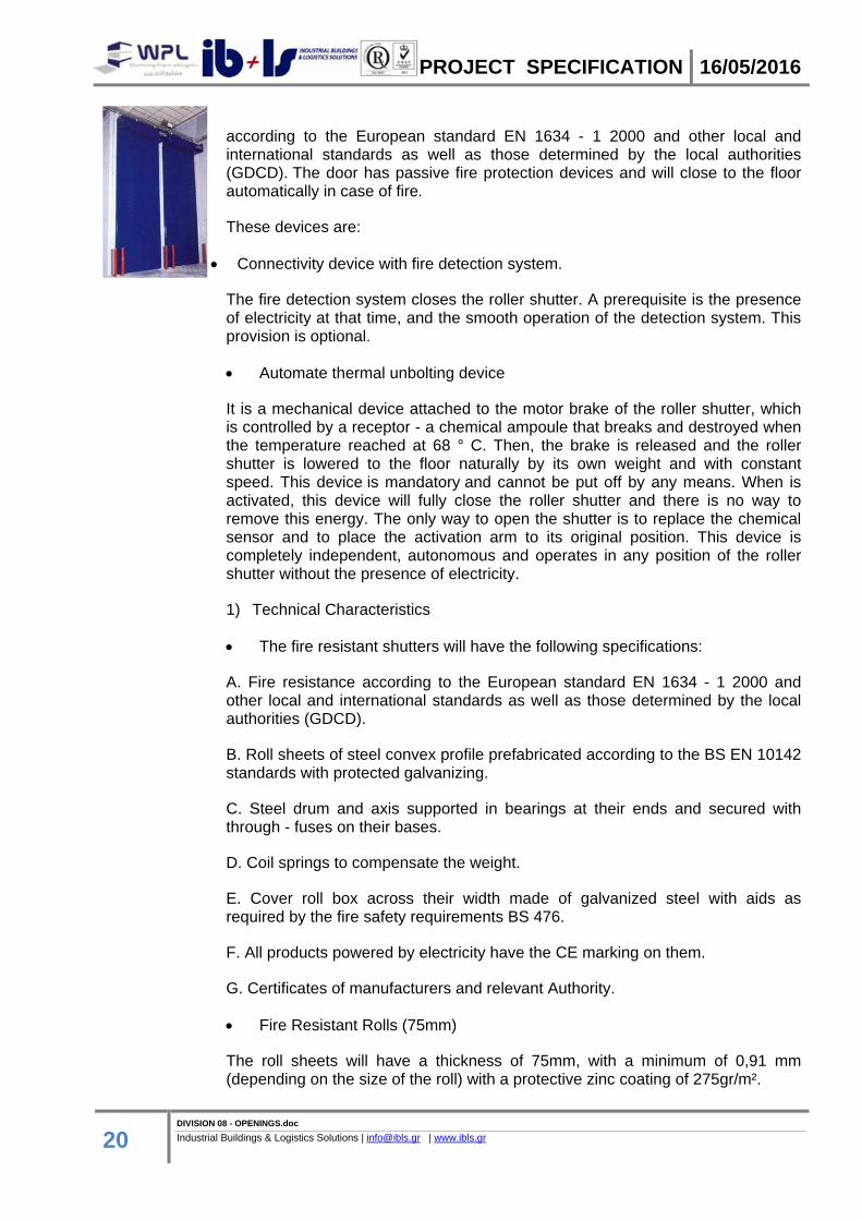
The fire-resistant roller shutter is a specialized construction of metallic roller shutter made from such materials so that the construction will present a specific coefficient or fire-resistance when the shutter is closed, which is certified
PROJECT SPECIFICATION 16/05/2016
20 DIVISION 08 - OPENINGS.doc Industrial Buildings & Logistics Solutions | [email protected] | www.ibls.gr
according to the European standard EN 1634 - 1 2000 and other local and international standards as well as those determined by the local authorities (GDCD). The door has passive fire protection devices and will close to the floor automatically in case of fire.
These devices are:
Connectivity device with fire detection system.
The fire detection system closes the roller shutter. A prerequisite is the presence of electricity at that time, and the smooth operation of the detection system. This provision is optional.
Automate thermal unbolting device
It is a mechanical device attached to the motor brake of the roller shutter, which is controlled by a receptor - a chemical ampoule that breaks and destroyed when the temperature reached at 68 ° C. Then, the brake is released and the roller shutter is lowered to the floor naturally by its own weight and with constant speed. This device is mandatory and cannot be put off by any means. When is activated, this device will fully close the roller shutter and there is no way to remove this energy. The only way to open the shutter is to replace the chemical sensor and to place the activation arm to its original position. This device is completely independent, autonomous and operates in any position of the roller shutter without the presence of electricity.
1) Technical Characteristics
The fire resistant shutters will have the following specifications:
A. Fire resistance according to the European standard EN 1634 - 1 2000 and other local and international standards as well as those determined by the local authorities (GDCD).
B. Roll sheets of steel convex profile prefabricated according to the BS EN 10142 standards with protected galvanizing.
C. Steel drum and axis supported in bearings at their ends and secured with through - fuses on their bases.
D. Coil springs to compensate the weight.
E. Cover roll box across their width made of galvanized steel with aids as required by the fire safety requirements BS 476.
F. All products powered by electricity have the CE marking on them.
G. Certificates of manufacturers and relevant Authority.
Fire Resistant Rolls (75mm)
The roll sheets will have a thickness of 75mm, with a minimum of 0,91 mm (depending on the size of the roll) with a protective zinc coating of 275gr/m².
PROJECT SPECIFICATION 16/05/2016
21 DIVISION 08 - OPENINGS.doc Industrial Buildings & Logistics Solutions | [email protected] | www.ibls.gr
The exact dimensions of the axis drum and the springs are proportional to the dimensions of the rolls and will be referred to in relevant technical brochures.
Drivers will be steel with a thickness of 3mm x (width) 65mm made according to the BS EN10142 standards, galvanized and mounted on angle 75 mm x 50 mm. The facility will be three-phase, the motion will be transported through a chain, an electric table, rotary terminals, a descent control system and a release mechanism; it will also have the ability to be manually pulled through a chain in case of power failure and through a control button of 3 positions.
The operation will be ensured by a "melting link" on top of the roll, a "solenoid" with waiting for command 24 V DC from a fire extinguishing system.
The parts that will not be galvanized shall be painted with rust primer and electrostatic paint in RAL color.
Note: The fire resistant rolls are designed to operate primarily in the event of fire and therefore their use should be limited and should be periodically tested through the test button.
On the perimeter of the rolls a special brush that restricts transmission of smoke will be placed.
PART 3 – EXECUTION
1) Installation
1. Install overhead coiling doors and operating equipment complete with necessary hardware, anchors, inserts, hangers, and equipment supports; according to manufacturer's written instructions and as specified.
2. Install overhead coiling doors, hoods, and operators at the mounting locations indicated for each door.
3. Accessibility: Install overhead coiling doors, switches, and controls along accessible routes in compliance with regulatory requirements for accessibility.
4. Fire-Rated Doors: Install according to NFPA 80, local and international standards as well as those determined by the local authorities (GDCD).
5. Smoke-Control Doors: Install according to NFPA 80 and NFPA 105.
2) Startup Service
1. Engage a factory-authorized service representative to perform startup service.
a. Perform installation and startup checks according to manufacturer's written instructions. b. Test and adjust controls and safeties. Replace damaged and malfunctioning controls and equipment.
PROJECT SPECIFICATION 16/05/2016
22 DIVISION 08 - OPENINGS.doc Industrial Buildings & Logistics Solutions | [email protected] | www.ibls.gr
c. Test door closing when activated by detector or alarm-connected fire-release system. Reset door-closing mechanism after successful test.
3) Adjusting
1. Adjust hardware and moving parts to function smoothly so that doors operate easily, free of warp, twist, or distortion.
2. Lubricate bearings and sliding parts as recommended by manufacturer.
3. Adjust seals to provide weathertight fit around entire perimeter.
D08.34. Special Function Doors
D08.34.13 Cold Storage Doors
PART 1 – GENERAL 1) Summary Cold storage door equipment will be installed in chill and refrigerated areas, in W12 and W13. The equipment includes cold storage sliding doors, cold storage fire escape exits, cold storage fire escape exits with access operation, cold storage fireproof doors and standard cold storage doors. 2) Submittals A. Shop drawings Show elevations of each door type, size of doors and frames, metal gages, details of door and frame construction, methods of anchorage, weather-stripping, provisions for and location of hardware, and details of installation. B. Manufacturer's Instructions Submit detail specifications and instructions for installation, adjustments, cleaning, and maintenance.
PART 2 – PRODUCTS
D08.34.13.01c.Cold Storage Sliding Doors
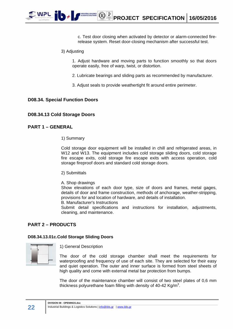
1) General Description
The door of the cold storage chamber shall meet the requirements for waterproofing and frequency of use of each site. They are selected for their easy and quiet operation. The outer and inner surface is formed from steel sheets of high quality and come with external metal bar protection from bumps.
The door of the maintenance chamber will consist of two steel plates of 0,6 mm thickness polyurethane foam filling with density of 40-42 Kg/m3.
PROJECT SPECIFICATION 16/05/2016
23 DIVISION 08 - OPENINGS.doc Industrial Buildings & Logistics Solutions | [email protected] | www.ibls.gr
The opening of the door will be towed - electromechanical with manual operation in case of power failure. Resistance in bumps will be around 1,8 kg/cm².
2) Technical Characteristics
Power supply : 400 V ~ 10% 50Hz (3F+N)
Gear motor input power supply 400 V
Output tension for auxiliary devices 24 V ~ 5%
Maximum current for auxiliary devices 500 m A
Operating temperature -20°C+50°C
Time of opening / closing 6 -600 sec.
Dimensions: As per attached drawings
Box protection degree ABS watertight IP 55
3) Safety Devices The automation device, fitted on the sliding door has been devised following meticulously the EN 12453:2000 norm as far as safety matter is concerned. From the interpretation of this norm, the hazardous situations raised from an automated sliding door operation are the following : - hazards caused by crushing and hazards caused by impact between the door blade and crossing people or vehicle In order to avoid such hazards, the automation is provided with an electro-sensitive protective equipment. 4) Safety edge The “conductive element” safety edge device detects eventual obstacles and blade impacts during the closing. Whether the closing door blade meets an obstacle, the Protected photo-cells safety edge intervenes stopping the sliding and inversing the direction until the opened door position will be reached. After a established period of time the door keeps on closing again 5) Flash Light The automation device is equipped with a flash light too, that with its flashing light advices in advance the door movement. 6) Emergency switch The system has an emergency switch that cuts the power supply to the gear motors and to the other devices. 7) Photo electric cells

PROJECT SPECIFICATION 16/05/2016
24 DIVISION 08 - OPENINGS.doc Industrial Buildings & Logistics Solutions | [email protected] | www.ibls.gr
The system has an input to connect one pair of photo cells (provided) that are carrying out the same function of the electronic safety edge, but avoiding the physical contact between the door blade and the crossing people and/or vehicle. 8) Internal push button This device provided with a lightning led, will allow the door opening from inside the cold room.
D08.34.13.02c.Cold Storage Fire Escape Exits
1) Item Description Cold storage fire escape exit doors is equipped with monolithic door blade, complete cladding with rounded edges and chromed convex corners and insulated with high density injected PU foam. It creates a contemporary design, taking always into consideration that has been designed to satisfy the stricter regulation as far as hygiene and safety are concerned. These doors are produced for both positive (CTN) and negative (CBT) temperature application, and are available in different colors and in stainless steel construction.
They will have the following characteristics:
A. Antiscratch, orange skin surface with insulating filler, thickness 50 or 60mm
B. Reversible door either left or right opening
C. Frame 53x55 or 65mm with detachable threshold
D. Durable hinges and closing regulator (fire rated doors)
E. Panic bars: The doors do not have a handle on the pull side (external). The doors can be opened only from the inside via the panic bar on the push (internal) side.
F. Doors that serve as part of means of egress shall meet the requirements of local and international standards as well as those determined by the local authorities (GDCD).
2) Dimensions
As per attached drawings
D08.34.13.03c.Cold Storage Fire Escape Exits With ACS Operation
1) Item Description Cold storage fire escape exit doors is equipped with monolithic door blade, complete cladding with rounded edges and chromed convex corners and insulated with high density injected PU foam. It creates a contemporary design, taking always into consideration that has been designed to satisfy the stricter regulation as far as hygiene and safety are concerned. These doors are
PROJECT SPECIFICATION 16/05/2016
25 DIVISION 08 - OPENINGS.doc Industrial Buildings & Logistics Solutions | [email protected] | www.ibls.gr
produced for both positive (CTN) and negative (CBT) temperature application, and are available in different colors and in stainless steel construction.
They will have the following characteristics:
A. Antiscratch, orange skin surface with insulating filler,thikness 50 or 60mm
B. Reversible door either left or right opening
C. Frame 53x55 or 65mm with detachable threshold
D. Durable hinges and closing regulator (fire rated doors)
E. Panic bars: The controlled opening direction is from the pull side of the door
(electric handle side). Locking the lock by key blocks the electric handle functioning, while opening is still possible via the panic bar on the push side.
F. Doors that serve as part of means of egress shall meet the requirements of local and international standards as well as those determined by the local authorities (GDCD).
G. Card-based Access Control System (ACS), as specified in D28.13.13.Access
Control Global Applications, D08.71.53.01c.Security Door Hardware and according to attached drawings.
2) Dimensions
As per attached drawings
D08.34.13.04c.Cold Storage Fire Proofed Doors
1) Item description
The chill and refrigerated areas will be equipped with fire proofed doors with an integrated insulation, in order to operate the required temperatures.
Cold storage fire proofed doors are equipped with monolithic door blade, complete cladding with rounded edges and chromed convex corners and insulated with high density injected PU foam. It creates a contemporary design, taking always into consideration that has been designed to satisfy the stricter regulation as far as hygiene and safety are concerned. These doors are produced for both positive (CTN) and negative (CBT) temperature application, and are available in different colors and in stainless steel construction.
Cold storage fire proofed doors must have:
Internal fireproof material that has a fire rating according to the local and international standards as well as those determined by the local authorities (GDCD).
Special smoke sealing material at the perimeter of the frame Panic bar at the opening's direction and re-close mechanism

PROJECT SPECIFICATION 16/05/2016
26 DIVISION 08 - OPENINGS.doc Industrial Buildings & Logistics Solutions | [email protected] | www.ibls.gr
Reversible opening either left or right The doors will be of opening or swinging type Secondary leaf with manual locking mechanism Durable hinges and closing regulator Waterproof skin surface.
At the perimeter of the frame, special thermo-expanding material which, in high temperatures expands and seals the opening, creating the desirable fire compartment.
2) Submittals
Shop Drawings: Show profiles, hardware, accessories, location and dimensions.
Product Data: Manufacturer’s technical data for each type of floor door, including setting drawings, templates, finish requirements, and details of anchorage devices.
Samples: Manufacturer to provide upon request, size to represent material adequately.
Manufacturer's Installation Instructions: Indicate installation requirements and rough-in dimensions.
3) Delivery, Storage and Handling
a. Deliver materials to Project site ready use.
b .Exercise proper care in handling of Work so as not to disrupt finished surfaces.
c. Store materials under cover in a dry and clean location off the ground.
4) Dimensions
As per attached drawings
PART 3 – EXECUTION 1) Automated cold storage sliding door use safety norms It is forbidden to cross the door during opening or closing. Never lean the arms, the hands, the head, the legs and feet out of the door closing line . Keep yourself always at a safety distance during the door blade movement. Never try to stop the door movement unless with the relevant emergency switch. Operate the door controls with gentleness avoiding exaggerated and unnecessary movement.
PROJECT SPECIFICATION 16/05/2016
27 DIVISION 08 - OPENINGS.doc Industrial Buildings & Logistics Solutions | [email protected] | www.ibls.gr
D08.34.53 Security Doors and Frames
PART 1 – GENERAL 1) General description For security needs of the facility, security doors will be installed where necessary. The doors' access can be controlled by Card-based Access Control System (ACS) per case, according to attached drawings and as specified in D28.13.13.Access Control Global Applications and D08.71.53.01c.Security Door Hardware. Design and construction of doors shall be manufacturer's standard with a UL 155 fire-resistant, exposure rating, bearing the UL label on the door and frame for the exposure rating required. Provide doors of the size indicated. The finish for door, frame, and hardware shall be the manufacturer's standard for the type door indicated. Provide each door equipped with a relocking device conforming to UL 140 and with an inner escape device that permits the bolt work to be released from inside the vault. [Escape mechanism to be panic bar type or other approved type requiring no tools or special instructions for operation.
2) Submittals A. Shop drawings Show elevations of each door type, size of doors and frames, metal gages, details of door and frame construction, methods of anchorage, weather-stripping, provisions for and location of hardware, and details of installation. B. Manufacturer's Instructions Submit detail specifications and instructions for installation, adjustments, cleaning, and maintenance.
PART 2 – PRODUCTS
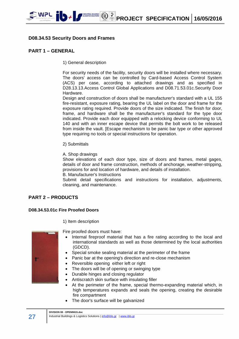
D08.34.53.01c Fire Proofed Doors
1) Item description Fire proofed doors must have: Internal fireproof material that has a fire rating according to the local and
international standards as well as those determined by the local authorities (GDCD).
Special smoke sealing material at the perimeter of the frame Panic bar at the opening's direction and re-close mechanism Reversible opening either left or right The doors will be of opening or swinging type Durable hinges and closing regulator Antiscratch skin surface with insulating filler At the perimeter of the frame, special thermo-expanding material which, in
high temperatures expands and seals the opening, creating the desirable fire compartment
The door's surface will be galvanized

PROJECT SPECIFICATION 16/05/2016
28 DIVISION 08 - OPENINGS.doc Industrial Buildings & Logistics Solutions | [email protected] | www.ibls.gr
2) Submittals
Shop Drawings: Show profiles, hardware, accessories, location and dimensions.
Product Data: Manufacturer’s technical data for each type of floor door, including setting drawings, templates, finish requirements, and details of anchorage devices.
Samples: Manufacturer to provide upon request, size to represent material adequately.
Manufacturer's Installation Instructions: Indicate installation requirements and rough-in dimensions.
3) Delivery, Storage and Handling
a. Deliver materials to Project site ready use.
b .Exercise proper care in handling of Work so as not to disrupt finished surfaces.
c. Store materials under cover in a dry and clean location off the ground.
4) Dimensions As per attached drawings
D08.34.53.02c.Fire Proofed Doors (Double sheet)
1) Item description Double sheet fire proofed doors will also be installed in areas needed. They will have the same requirements as the D08.34.53.01c Fire Proofed Doors.
D08.34.53.03c.Fire Proofed Doors with ACS Operation
1) Item description Fire proofed doors with access operation will have the same specifications with D08.34.53.01c Fire Proofed Doors and will have additionally a Card-based Access Control System (ACS), as specified in D28.13.13.Access Control Global Applications, D08.71.53.01c.Security Door Hardware and according to attached drawings.
PART 3 – EXECUTION
1) Examination
Verify that preparation and affected dimensions are acceptable. Verify tolerances and correct improper conditions.

PROJECT SPECIFICATION 16/05/2016
29 DIVISION 08 - OPENINGS.doc Industrial Buildings & Logistics Solutions | [email protected] | www.ibls.gr
2) Preparation
Advise installers of details relating to floor hatch installation, including rough opening dimensions, locations of supports, and anchoring methods.
3) Installation
a .Follow manufacturer’s instructions for installing floor doors and hatches. b. Install frames plumb and level in opening, in proper alignment with floor surface for flush installation. Secure rigidly in place. c. Position units to provide convenient access to concealed Work requiring access.
4) Clean and adjust
a. Clean adjacent surfaces and remove unused product and debris from site. b. Adjust doors for smooth operation.
D08.36. Panel Doors
D08.36.13 Sectional Doors
PART 1 – GENERAL
1) Description Of Work
This specification covers the furnishing and installation of material for sectional overhead doors.
Products shall be as follows or as directed by the Owner. Installation procedures shall be in accordance with the products manufacturer’s recommendations. Demolition and removal of materials shall be as required to support the work.
2) Summary
Section includes manually OR electrically, as directed, operated sectional doors with integral pass doors, as directed.
3) Performance Requirements
1. General Performance: Sectional doors shall meet performance requirements specified without failure due to defective manufacture, fabrication, installation, or other defects in construction and without requiring temporary installation of reinforcing components.
2. Delegated Design: Design sectional doors, including comprehensive engineering analysis by a qualified professional engineer, using performance requirements and design criteria indicated.
PROJECT SPECIFICATION 16/05/2016
30 DIVISION 08 - OPENINGS.doc Industrial Buildings & Logistics Solutions | [email protected] | www.ibls.gr
3. Structural Performance: Exterior sectional doors shall withstand the effects of gravity loads, and the following loads and stresses within limits and under conditions indicated according to ASCE/SEI 7.
a. Wind Loads: As indicated on Drawings OR Uniform pressure (velocity pressure) of 20 lbf/sq. ft. (960 Pa), acting inward and outward, as directed.
1) Basic Wind Speed: 85 mph (38 m/s) OR 90 mph (40 m/s) OR 100 mph (44 m/s) OR 110 mph (49 m/s), as directed.
2) Exposure Category: A OR B OR C OR D, as directed.
b. Deflection Limits: Design sectional doors to withstand design wind loads without evidencing permanent deformation or disengagement of door components. Deflection of door in horizontal position (open) shall not exceed 1/120 of the door width.
4. Air Infiltration: Maximum rate not more than indicated when tested according to ASTM E 283 OR DASMA 105, as directed.
a. Air Infiltration: Maximum rate of 0.08 cfm/sq. ft. (0.406 L/s per sq. m) at 15 and 25 mph (24.1 and 40.2 km/h).
5. Windborne-Debris-Impact-Resistance Performance: Provide sectional doors OR glazed sectional doors, as directed, that pass large-missile-impact and cyclic-pressure tests when tested according to ASTM E 1886 and ASTM E 1996 OR DASMA 115, as directed.
6. Seismic Performance: Sectional doors shall withstand the effects of earthquake motions determined according to ASCE/SEI 7.
a. The term "withstand" means "the unit will remain in place without separation of any parts from the device when subjected to the seismic forces specified."
b. Seismic Component Importance Factor: 1.5 OR 1.0, as directed.
7. Operation Cycles: Provide sectional door components and operators capable of operating for not less than number of cycles indicated for each door. One operation cycle is complete when a door is opened from the closed position to the fully open position and returned to the closed position.
4) Submittals
1. Product Data: For each type and size of sectional door and accessory.
2. Shop Drawings: For each installation and for special components not dimensioned or detailed in manufacturer's product data. Include plans, elevations, sections, details, and attachments to other work.
a. Wiring Diagrams: For power, signal, and control wiring.
PROJECT SPECIFICATION 16/05/2016
31 DIVISION 08 - OPENINGS.doc Industrial Buildings & Logistics Solutions | [email protected] | www.ibls.gr
3. Samples: For each exposed product and for each color and texture specified.
4. Delegated-Design Submittal: For sectional doors indicated to comply with performance requirements and design criteria, including analysis data signed and sealed by the qualified professional engineer responsible for their preparation.
5. Seismic Qualification Certificates: For sectional doors, accessories, and components, from manufacturer.
6. Maintenance data.
7. Warranties: Sample of special warranties.
5) Quality Assurance
1. Installer Qualifications: Manufacturer's authorized representative who is trained and approved for both installation and maintenance of units required for this Project.
2. Electrical Components, Devices, and Accessories: Listed and labeled as defined in NFPA 70, by a qualified testing agency, and marked for intended location and application.
3. Standard for Sectional Doors: Fabricate sectional doors to comply with DASMA 102 unless otherwise indicated.
4. Regulatory Requirements: Comply with applicable provisions in the U.S. Architectural & Transportation Barriers Compliance Board's "Americans with Disabilities Act (ADA) and Architectural Barriers Act (ABA) Accessibility Guidelines for Buildings and Facilities" and ICC/ANSI A117.1, as directed.
6) Warranty
1. Special Warranty: Manufacturer's standard form in which manufacturer agrees to repair or replace components of sectional doors that fail in materials or workmanship within Two OR Five, as directed, years from date of Substantial Completion.
2. Special Finish Warranty: Manufacturer's standard form in which manufacturer agrees to repair or replace components that show evidence of deterioration of factory-applied finishes within 10 years from date of Substantial Completion.
PART 2 – PRODUCTS
D08.36.13.01c Industrial Doors
1) Item Description
PROJECT SPECIFICATION 16/05/2016
32 DIVISION 08 - OPENINGS.doc Industrial Buildings & Logistics Solutions | [email protected] | www.ibls.gr
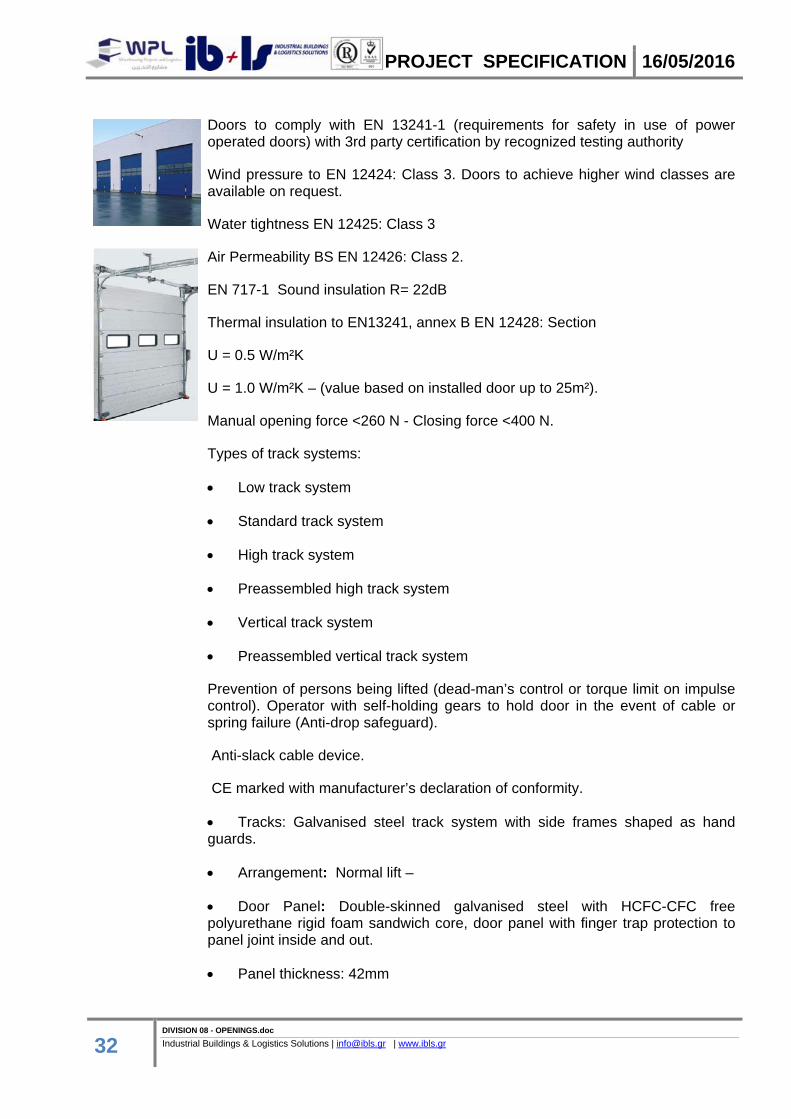
Doors to comply with EN 13241-1 (requirements for safety in use of power operated doors) with 3rd party certification by recognized testing authority
Wind pressure to EN 12424: Class 3. Doors to achieve higher wind classes are available on request.
Water tightness EN 12425: Class 3
Air Permeability BS EN 12426: Class 2.
EN 717-1 Sound insulation R= 22dB
Thermal insulation to EN13241, annex B EN 12428: Section
U = 0.5 W/m²K
U = 1.0 W/m²K – (value based on installed door up to 25m²).
Manual opening force <260 N - Closing force <400 N.
Types of track systems:
Low track system
Standard track system
High track system
Preassembled high track system
Vertical track system
Preassembled vertical track system
Prevention of persons being lifted (dead-man’s control or torque limit on impulse control). Operator with self-holding gears to hold door in the event of cable or spring failure (Anti-drop safeguard).
Anti-slack cable device.
CE marked with manufacturer’s declaration of conformity.
Tracks: Galvanised steel track system with side frames shaped as hand guards.
Arrangement: Normal lift –
Door Panel: Double-skinned galvanised steel with HCFC-CFC free polyurethane rigid foam sandwich core, door panel with finger trap protection to panel joint inside and out.
Panel thickness: 42mm
PROJECT SPECIFICATION 16/05/2016
33 DIVISION 08 - OPENINGS.doc Industrial Buildings & Logistics Solutions | [email protected] | www.ibls.gr
S-ribbed: Stucco-textured inside and outside vertically ribbed at 125mm increments.
L-ribbed: Micrograin outside, stucco-textured inside.
Panel depth: 750 / 625mm up to 6000mm wide.
Finish:
S-ribbed: Polyester stucco embossed coating on both sides.
L-ribbed: Fine lines with a smooth surface. Internal colour: Off White - RAL 9002.
Standard external colours: White - RAL 9016 / Pure White - RAL 9010 / Grey Aluminium - RAL 9007 / White Aluminium - RAL 9006 / Grey White - RAL 9002 / Terra Brown - RAL 8028 / Anthracite Grey - RAL 7016 / Moss Green - RAL 6005 / Leaf Green - RAL 6002 / Gentian Blue - RAL 5010 / Azure Blue - RAL 5009 / Ultramarine Blue - RAL 5002 / Fire Red - RAL 3000 / Rape Yellow - RAL 1021 / Poppy red / Goosewing Grey / Merlin Grey / Olive Green / Sapphire Blue RAL5003.
Options:
Vision panels: Type A: DURATEC scratch resistant coating, acrylic double glazed 26mmclear vision panels (635mm wide x 245mm high) with black synthetic frame. Number of windows dependant on door width.
Power operation: 400v 3 phase operator with emergency hand chain operation in case of power failure, with automatic reset. (220v single phase as above available as option for doors up to max 4500mm wide and 4500mm high)
Control: A 435 Pre-wired control unit. Impulse control including Opto-sensor self-monitoring bottom safety edge. Omission of closing edge safety device required dead man control.
Manual operation: Rope pulley hoist - Chain hoist.
Ironmongery: Security anti-lift device (standard on electric doors only). Shoot bolt (standard on manual doors) complete with electrical interlock switch, operation side.
Other requirements: Wicket Door without threshold (trip free). Outward opening inset wicket personnel door (position dependent on door width) complete with profile cylinder mortise lock, black plastic lever handle set, door closer and electrical interlock switch.
PART 3 – EXECUTION
1) Installation
PROJECT SPECIFICATION 16/05/2016
34 DIVISION 08 - OPENINGS.doc Industrial Buildings & Logistics Solutions | [email protected] | www.ibls.gr
1. Install sectional doors and operating equipment complete with necessary hardware, anchors, inserts, hangers, and equipment supports; according to manufacturer's written instructions and as specified.
2. Tracks:
a. Fasten vertical track assembly to opening jambs and framing, spaced not more than 24 inches (610 mm) apart. b. Hang horizontal track assembly from structural overhead framing with angles or channel hangers attached to framing by welding or bolting, or both. Provide sway bracing, diagonal bracing, and reinforcement as required for rigid installation of track and door-operating equipment. c. Repair galvanized coating on tracks according to ASTM A 780.
3. Accessibility: Install sectional doors, switches, and controls along accessible routes in compliance with regulatory requirements for accessibility.
2) Startup Services
1. Engage a factory-authorized service representative to perform startup service.
a. Complete installation and startup checks according to manufacturer's written instructions. b. Test and adjust controls and safeties. Replace damaged and malfunctioning controls and equipment.
3) Adjusting
1. Adjust hardware and moving parts to function smoothly so that doors operate easily, free of warp, twist, or distortion.
2. Lubricate bearings and sliding parts as recommended by manufacturer.
3. Adjust doors and seals to provide weathertight fit around entire perimeter.
4. Align and adjust motors, pulleys, belts, sprockets, chains, and controls according to manufacturer's written instructions.
5. Touch-up Painting: Immediately after welding galvanized materials, clean welds and abraded galvanized surfaces and repair galvanizing to comply with ASTM A 780.

PROJECT SPECIFICATION 16/05/2016
35 DIVISION 08 - OPENINGS.doc Industrial Buildings & Logistics Solutions | [email protected] | www.ibls.gr
D08.71. Door Hardware
D08.71.53.Security Door Hardware
PART 1 – GENERAL 1) Description of Work
This specification covers the furnishing and installation of material for door hardware. Products shall be as follows or as directed by the Owner. Installation procedures shall be in accordance with the products manufacturer’s recommendations. Demolition and removal of materials shall be as required to support the work.
2) Summary
This Section includes the following:
a. Mechanical door hardware
b. Cylinders for doors specified in other Sections.
Products furnished, but not installed, under this Section include the products listed below. Coordinating, purchasing, delivering, and scheduling remain requirements of this Section.
a. Pivots, thresholds, weather stripping, and cylinders for locks specified in other Sections.
b. Permanent cores to be installed by the Owner.
3) Quality Assurance
Installer Qualifications: An employer of workers trained and approved by lock manufacturer.
a. Installer's responsibilities include supplying and installing door hardware and providing a qualified Architectural Hardware Consultant available during the course of the Work to consult with Contractor, Architect, and the Owner about door hardware and keying
Architectural Hardware Consultant Qualifications: A person who is currently certified by DHI as an Architectural Hardware Consultant and who is experienced in providing consulting services for door hardware installations that are comparable in material, design, and extent to that indicated for this Project.
Source Limitations: Obtain each type of door hardware from a single manufacturer.
a. Provide electrified door hardware from same manufacturer as mechanical door hardware, unless otherwise indicated.

PROJECT SPECIFICATION 16/05/2016
36 DIVISION 08 - OPENINGS.doc Industrial Buildings & Logistics Solutions | [email protected] | www.ibls.gr
Manufacturers that perform electrical modifications and that are listed by a testing and inspecting agency acceptable to authorities having jurisdiction are acceptable.
Fire-Rated Door Assemblies: Where fire-rated door assemblies are indicated, provide door hardware rated for use in assemblies complying with NFPA 80 that are listed and labeled by a qualified testing, for fire protection ratings indicated, based on testing at positive pressure according to NFPA 252 OR UL 10C, unless otherwise indicated.
Smoke- and Draft-Control Door Assemblies: Where smoke- and draft-control door assemblies are required, provide door hardware that meet requirements of assemblies tested according to UL 1784 and installed in compliance with NFPA 105.
a. Air Leakage Rate: Maximum air leakage of 0.3 cfm/sq. ft. (3 cu. m per minute/sq. m) at the tested pressure differential of 0.3-inch wg (75 Pa) of water.
Means of Egress Doors: Latches do not require more than 15 lbf (67 N) to release the latch. Locks do not require use of a key, tool, or special knowledge for operation.
Accessibility Requirements: For door hardware on doors in an accessible route, comply with the U.S. Architectural & Transportation Barriers Compliance Board's ADA-ABA Accessibility Guidelines OR ICC/ANSI A117.1 OR HUD's "Fair Housing Accessibility Guidelines", as directed.
1. Provide operating devices that do not require tight grasping, pinching, or twisting of the wrist and that operate with a force of not more than 5 lbf (22.2 N).
2. Comply with the following maximum opening-force requirements:
a. Interior, Non-Fire-Rated Hinged Doors: 5 lbf (22.2 N) applied perpendicular to door.
b. Sliding or Folding Doors: 5 lbf (22.2 N) applied parallel to door at latch.
c. Fire Doors: Minimum opening force allowable by authorities having jurisdiction.
3. Bevel raised thresholds with a slope of not more than 1:2. Provide thresholds not more than 1/2 inch (13 mm) high and 3/4 inch (19 mm) high for exterior sliding doors.
4. Adjust door closer sweep periods so that, from an open position of 70 degrees, the door will take at least 3 seconds to move to a point 3 inches (75 mm) from the latch, measured to the leading edge of the door.
Preinstallation Conference: conduct conference at Project site.

PROJECT SPECIFICATION 16/05/2016
37 DIVISION 08 - OPENINGS.doc Industrial Buildings & Logistics Solutions | [email protected] | www.ibls.gr
a. Review and finalize construction schedule and verify availability of materials, Installer’s personnel, equipment, and facilities needed to make progress and avoid delays.
b. Inspect and discuss preparatory work performed by other trades.
c. Inspect and discuss electrical roughing in for electrified door hardware.
d. Review sequence of operation for each type of electrified door hardware.
e. Review required testing, inspecting, and certifying procedures.
4) Delivery, Storage and Handling
Inventory door hardware on receipt and provide secure lock-up for door hardware delivered to Project site.
Tag each item or package separately with identification coordinated with the final door hardware schedule, and include installation instructions, templates, and necessary fasteners with each item or package.
Deliver keys to manufacturer of key control system for subsequent delivery to the Owner.
Deliver keys and permanent cores to the Owner by registered mail or overnight package service.
5) Warranty
Special Warranty: Manufacturer's standard form in which manufacturer agrees to repair or replace components of door hardware that fail in materials or workmanship within specified warranty period.
1. Failures include, but are not limited to, the following:
a. Structural failures including excessive deflection, cracking, or breakage.
b. Faulty operation of doors and door hardware.
c. Deterioration of metals, metal finishes, and other materials beyond normal weathering and use.
2. Warranty Period: Three years from date of Substantial Completion, except as follows:
a. Electromagnetic or Delayed-Egress Locks: Five years from date of Substantial Completion.
b. Exit Devices: Two years from date of Substantial Completion.

PROJECT SPECIFICATION 16/05/2016
38 DIVISION 08 - OPENINGS.doc Industrial Buildings & Logistics Solutions | [email protected] | www.ibls.gr
c. Manual Closers: 10 years from date of Substantial Completion.
d. Concealed Floor Closers: Five OR 10 OR 25 years from date of Substantial
PART 2 – PRODUCTS
D08.71.53.01c.Security Door Hardware
1) Item Description
Hinges
1. Hinges: BHMA A156.1. Provide template-produced hinges for hinges installed on hollow-metal doors ad hollow-metal frames.
2. Antifriction-Bearing Hinges:
a. Mounting: Full-Mortise (Butt) OR Half mortise OR Full surface OR Half surface, as directed.
b. Bearing Material: Manufacturer’s standard antifriction bearing OR Ball bearing, as directed.
c. Grade: Grade 1 (heavy weight) OR Grade 2 (standard weight), as directed.
d. Base and Pin Metal:
1. Exterior Hinges: Stainless steel with stainless-steel pin OR Brass with stainlesssteel pin body and brass protruding heads, as directed. 2. Interior Hinges: Brass with stainless-steel pin body and brass protruding heads OR Steel with steel pin OR Stainless steel with stainless-steel pin, as directed. 3. Hinges for Fire-Rated Assemblies: Steel with steel pin OR Stainless steel with stainless-steel pin, as directed.
e. Pins: Non-rising loose unless otherwise indicated OR Maximum security OR Nonremovable, as directed.
1. Outswinging Exterior Doors: Maximum security OR Nonremovable, as directed. 2. Outswinging Corridor Doors with Locks: Maximum security OR Nonremovable, as directed.
f. Tips: Flat button OR Hospital OR Oval OR Ball OR Steeple OR Urn OR Acorn, as directed.
g. Corners: Square OR 5/32-inch (4-mm) radius OR 1/4-inch (6-mm) radius OR 5/8-inch (16- mm) radius, as directed.
PROJECT SPECIFICATION 16/05/2016
39 DIVISION 08 - OPENINGS.doc Industrial Buildings & Logistics Solutions | [email protected] | www.ibls.gr
h. Options: Raised barrel OR Reverse safety stud OR Safety stud, as directed.
3. Self-Closing Hinges and Pivots
a. Self-Closing Hinges and Pivots: BHMA A156.17.
b. Spring Hinges: Grade 1 OR Grade 2, as directed; wrought steel, with torsion spring.
1. Type: Single OR Double, as directed acting. 2. Mounting: Full mortise (butts) OR Half mortise OR Full surface OR Half surface, as directed.
c. Horizontal-Spring Pivot Sets: Grade 3; double acting; non-handed; consisting of wrought steel bottom pivot hinge with antifriction bearing and nylon top pivot and socket.
1. Type: Hold-open OR Non-hold open, as directed. 2. Tension: Adjustable OR Fixed, as directed. 3. Bottom Pivot Trim: Steel OR Brass, as directed. 4. Bottom Plate: For bottom hinge attachment to floor OR jamb, as directed.
d. Gate-Spring Pivot Sets: Grade 1; double acting; non-handed; consisting of bottom pivot with door and jamb bracket and top pivot assembly with jamb bracket.
1. Mounting: Mortise OR Surface, as directed. 2. Tension: Adjustable OR Fixed, as directed. 3. Base Metal: Cast, forged, or extruded brass or bronze OR Malleable iron, as directed.
e. Gravity Pivot Sets: Grade 3; double acting; surface mounting; non-handed; consisting of bottom pivot with door and jamb bracket and top pivot assembly with jamb bracket.
1. Tension: Adjustable OR Fixed, as directed. 2. Base Metal: Wrought brass or bronze OR Steel, as directed.
4. Mechanical Locks and Latches
a. Lock Functions: As indicated in door hardware schedule.
b. Lock Throw: Comply with testing requirements for length of bolts required for labeled fire doors, and as follows:
1. Bored Locks: Minimum 1/2-inch (13-mm) latchbolt throw. 2. Mortise Locks: Minimum 3/4-inch (19-mm) latchbolt throw. 3. Deadbolts: Minimum 1-inch (25-mm) OR 1.25-inch (32-mm) bolt throw, as directed.
c. Lock Backset: 2-3/4 inches (70 mm), unless otherwise indicated.

PROJECT SPECIFICATION 16/05/2016
40 DIVISION 08 - OPENINGS.doc Industrial Buildings & Logistics Solutions | [email protected] | www.ibls.gr
d. Lock Trim:
1. Description: As indicated on Drawings, as directed. 2. Levers: Wrought OR Forged OR Cast, as directed. 3. Knobs: Wrought OR Forged OR Cast, as directed. 4. Escutcheons (Roses): Wrought OR Forged OR Cast, as directed. 5. Dummy Trim: Match knob OR lever, lock trim and escutcheons. 6. Operating Device: Lever OR Knob, as directed with escutcheons (roses).
a. Strikes: Provide manufacturer's standard strike for each lock bolt or latchbolt complying with requirements indicated for applicable lock or latch and with strike box and curved lip extended to protect frame; finished to match lock or latch.
1. Flat-Lip Strikes: For locks with three-piece antifriction latchbolts, as recommended by manufacturer. 2. Extra-Long-Lip Strikes: For locks used on frames with applied wood casing trim. 3. Aluminum-Frame Strike Box: Manufacturer's special strike box fabricated for aluminum framing. 4. Rabbet Front and Strike: Provide on locksets for rabbeted meeting stiles.
b. Bored Locks: BHMA A156.2; Grade 1 OR 2, as directed; Series 4000.
c. Mortise Locks: BHMA A156.13; Operational OR Security, as directed Grade 1 OR 2, as directed; stamped steel case with steel or brass parts; Series 1000.
d. Interconnected Locks: BHMA A156.12; Grade 1 OR 2, as directed; Series 5000.
e. Roller Latches: BHMA A156.16; Grade 1; rolling plunger that engages socket or catch, with adjustable roller projection.
1. Material: Brass OR Bronze, as directed. 2. Mounting: Surface OR Mortise, as directed.
f. Push-Pull Latches: Bored, BHMA A156.2; Series 4000 OR Mortise, BHMA A156.13, as directed; Grade 1 OR 2, as directed; with paddle handles that retract latchbolt; capable of being mounted vertically or horizontally.
1. Lever and Escutcheon Material: Brass OR Bronze OR Stainless steel OR Aluminum, as directed. 2. Lettering: Engrave with the words "Pull" and "Push." 3. Lead Lining: 0.047 inch (1.2 mm) thick for escutcheon plate.
5. Electromechanical Locks and Exit Alarms

PROJECT SPECIFICATION 16/05/2016
41 DIVISION 08 - OPENINGS.doc Industrial Buildings & Logistics Solutions | [email protected] | www.ibls.gr
General:
a. Grade 1 for type of lock indicated; motor or solenoid driven.
b. Mortise deadlocking latchbolts.
1. Single-Door OR Pairs-of-Door Type, as directed: Activated by arm, push plate, or paddle OR horizontal bar, as directed. 2. Electrical modifications:
Locks indicated to have RQE (request to exit) switches shall incorporate internal SPDT contacts for remote signaling of operation of the inside lever handle. Switches shall be used in conjunction with the specified monitor switches and the security control system to accommodate "authorized egress".
Locks indicated to electrically lock (FAIL SAFE) or electrically unlock (FAIL SECURE), as indicated, shall actuate upon receipt of a 24V signal and will remain in this mode until signal is interrupted.
3. Options: Audible alarm that sounds when unauthorized use of
door occurs. Silent alarm with remote signal capability for
connection to remote indicating panel. Strike: Surface OR Mortise, as directed.
6. Exit Devices and Auxiliary Items
a. Exit Devices and Auxiliary Items: BHMA A156.3, Grade 1 OR Grade 2. Listed under Category G in BHMA's "Certified Product Directory"
b. Accessibility Requirements: Where handles, pulls, latches, locks, and other operating devices are indicated to comply with accessibility requirements, comply with the U.S. Architectural & Transportation Barriers Compliance Board's "Americans with Disabilities Act (ADA), Accessibility Guidelines for Buildings and Facilities (ADAAG)."
1. Provide operating devices that do not require tight grasping, pinching, or twisting of the wrist and that operate with a force of not more than 22N.
c. Exit Devices for Means of Egress Doors: Comply with NFPA 101. Exit devices shall not require more than 67N to release the latch. Locks shall not require the use of a key, tool, or special knowledge for operation.
d. Panic Exit Devices: Listed and labeled by a testing and inspecting agency acceptable to authorities having jurisdiction, for panic protection, based on testing according to UL 305.
PROJECT SPECIFICATION 16/05/2016
42 DIVISION 08 - OPENINGS.doc Industrial Buildings & Logistics Solutions | [email protected] | www.ibls.gr
e. Fire Exit Devices: Devices complying with NFPA 80 that are listed and labeled by a testing and inspecting agency acceptable to authorities having jurisdiction, for fire and panic protection, based on testing according to UL 305 and NFPA 252.
f. Outside Trim: Lever with cylinder; material and finish to match locksets, unless otherwise indicated. Match design for locksets and latchsets, unless otherwise indicated
g. Electrical Modifications:
1. Exit devices indicated to have “request-to-exit” switches shall incorporate internal SPDT contacts for remote signaling of operation of the push pad. Switches shall be used in conjunction with the specified monitor switches and the security control system to accommodate "authorized egress".
2. Exit devices indicated to have electric latch retraction shall be modified to electrically unlatch (dog down) upon receipt of a 24V signal and will remain unlatched until signal is interrupted.
3. Exit devices indicated to electrically lock (FAIL SAFE) or electrically unlock (FAIL SECURE), as indicated, shall actuate upon receipt of a 24V signal and will remain in this mode until signal is interrupted.
7. Lock Cylinders
a. Lock Cylinders: Tumbler type, constructed from brass or bronze, stainless steel, or nickel silver.
b. Standard Lock Cylinders: BHMA A156.5; Grade 1 OR 1A OR 2, as directed; permanent cores that are interchangeable OR removable, as directed; face finished to match lockset.
1. Number of Pins: Five OR Six OR Seven, as directed. 2. Type: Mortise OR Rim OR Bored-lock, as directed type.
c. High-Security Lock Cylinders: BHMA A156.30; Grade 1 OR 2 OR 3, as directed; Type M, mechanical OR E, electrical, as directed; permanent cores that are removable; face finished to match lockset.
1. Number of Pins: Six OR Seven, as directed. 2. Type: Mortise OR Rim OR Bored-lock, as directed type.
d. Construction Master Keys: Provide cylinders with feature that permits voiding of construction keys without cylinder removal. Provide 10 construction master keys.
PROJECT SPECIFICATION 16/05/2016
43 DIVISION 08 - OPENINGS.doc Industrial Buildings & Logistics Solutions | [email protected] | www.ibls.gr
e. Construction Cores: Provide construction cores that are replaceable by permanent cores. Provide 10 construction master keys.
8. Keying
a. Keying System: Factory registered, complying with guidelines in BHMA A156.28, Appendix A. Incorporate decisions made in keying conference.
1. No Master Key System: Only change keys operate cylinder. 2. Master Key System: Change keys and a master key operate cylinders. 3. Grand Master Key System: Change keys, a master key, and a grand master key operate cylinders. 4. Great-Grand Master Key System: Change keys, a master key, a grand master key, and a great-grand master key operate cylinders. 5. Existing System:
Master key or grand master key locks to Owner's existing system.
Re-key Owner's existing master key system into new keying system.
6. Keyed Alike: Key all cylinders to same change key.
b. Keys: Nickel silver OR Brass, as directed.
1. Stamping: Permanently inscribe each key with a visual key control number and include the following notation:
Notation: "DO NOT DUPLICATE." OR Information to be furnished by Owner., as directed
2. Quantity: In addition to one extra key blank for each lock, provide the following:
Cylinder Change Keys: Three. Master Keys: Five. Grand Master Keys: Five. Great-Grand Master Keys: Five.
9. Mechanical Stops and Holders
a. Wall- and Floor-Mounted Stops: BHMA A156.16; polished cast brass, bronze, or aluminum base metal, as directed.
b. Rigid-Type Floor Stop: Grade 1 OR 2, as directed; with rubber bumper; for surface-screw OR expansion-shield, as directed application.
c. Dome-Type Floor Stop: Grade 1 OR 2, as directed; with minimum 1-inch- (25-mm-) high bumper for doors without threshold and 1-3/8-inch- (35-mm-) high bumper for doors with threshold; provide with extruded aluminum riser for carpet installations.
PROJECT SPECIFICATION 16/05/2016
44 DIVISION 08 - OPENINGS.doc Industrial Buildings & Logistics Solutions | [email protected] | www.ibls.gr
d. Combination Floor Stop and Holder: Grade 1 OR 2, as directed; for surface-screw OR expansion-shield application, as directed; with semiautomatic hold open OR automatic hold open and release by pushing door, as directed.
e. Manual Combination Floor Stop and Holder: Grade 1 OR 2, as directed; 3-1/2 inches (89 mm) long, with holder, keeper, and rubber bumper; for surface-screw OR expansion-shield application, as directed.
f. Chain Door Stops: Grade 2; welded chain, each end attached to compression springs, both covered with protective sleeve; for surface-screw application.
g. Wall Bumpers: Grade 1 OR 2, as directed; with rubber bumper; 2-1/2-inch (64-mm) diameter, minimum 3/4-inch (19-mm) projection from wall; with backplate for concealed fastener installation; with convex OR concave, as directed bumper configuration.
h. Roller-Type Wall Bumpers: Grade 1 OR 2, as directed; minimum 4-3/8-inch (111-mm) projection from wall; for surface-screw application.
i. Lever-Type Door Holders: Grade 1 OR 2, as directed; minimum 4-inch- (102-mm-) long arm that swings up and remains in vertical position; with replaceable rubber tip; for surface-screw application.
j. Plunger-Type Door Holders: Grade 1 OR 2, as directed; minimum 1-1/8-inch (29-mm) plunger throw; with replaceable rubber tip; for surface-screw application.
10. Thresholds
a. Thresholds: BHMA A156.21; fabricated to full width of opening indicated.
b. Compressing-Top Thresholds: Metal member with compressible vinyl seal on top of threshold that seals against bottom of door; and base metal of aluminum OR extruded bronze OR stainless steel, as directed.
c. Saddle Thresholds:
1. Type: Smooth top OR Fluted top OR Fluted top and offset OR Thermal break and fluted top OR Applied gasketed stop and fluted top OR Carpet separator with fluted top OR Fluted top, barrier free, as directed. 2. Base Metal: Aluminum OR Extruded bronze OR Stainless steel, as directed.
d. Half-Saddle Thresholds: Fluted-top metal member; and base metal of aluminum OR extruded bronze, as directed.
PROJECT SPECIFICATION 16/05/2016
45 DIVISION 08 - OPENINGS.doc Industrial Buildings & Logistics Solutions | [email protected] | www.ibls.gr
e. Interlocking Thresholds: Fluted-top metal member with integral lip designed to engage a hook strip applied to door.
1. Type: Single lip OR Double lip OR Double-lip water return OR Double-lip water return with aluminum pan OR Single lip with thermal barrier, as directed. 2. Base Metal: Aluminum OR Extruded bronze, as directed.
f. Latching/Rabbeted Thresholds:
1. Type: Fluted OR Smooth OR Offset with fluted top, as directed. 2. Base Metal: Aluminum OR Extruded bronze, as directed.
g. Latching/Rabbeted Thresholds with Gasket: Fluted-top metal member with gasket.
1. Type: Offset OR Thermal barrier, as directed. 2. Base Metal: Aluminum OR Extruded bronze, as directed. 3. Gasket Material: Vinyl OR Silicone OR Neoprene OR Brush pile OR Closed-cell sponge neoprene, as directed.
h. Latching/Rabbeted Panic Thresholds:
1. Type: Fluted, barrier free OR Fluted with gasket top, as directed. 2. Base Metal: Aluminum OR Extruded bronze, as directed.
i. Plate Thresholds: Solid metal plate.
1. Top Surface: Fluted OR Fluted with slip-resistant abrasive, as directed. 2. Base Metal: Aluminum OR Extruded brass or bronze OR Stainless steel, as directed.
j. Ramped Thresholds: Modular, interlocking, sloped, fluted-top metal assemblies with closed return ends; 1:12 slope.
1. Top Surface: Fluted OR Fluted with slip-resistant abrasive, as directed. 2. Base Metal: Aluminum OR Extruded bronze, as directed.
k. Saddle Thresholds for Floor Closers: Fluted top.
1. Type: Type A, for center-hung doors; ends not mitered OR Type B, for offset-hung doors; ends not mitered OR Type C, for center-hung doors; ends mitered OR Type D, for offsethung doors; ends mitered, as directed. 2. Base Metal: Aluminum OR Extruded bronze, as directed.
11. Fabrication

PROJECT SPECIFICATION 16/05/2016
46 DIVISION 08 - OPENINGS.doc Industrial Buildings & Logistics Solutions | [email protected] | www.ibls.gr
a. Manufacturer's Nameplate: Do not provide products that have manufacturer's name or trade name displayed in a visible location except in conjunction with required fire-rated labels and as otherwise approved by the Owner.
1. Manufacturer's identification is permitted on rim of lock cylinders only.
b. Base Metals: Produce door hardware units of base metal indicated, fabricated by forming method indicated, using manufacturer's standard metal alloy, composition, temper, and hardness. Furnish metals of a quality equal to or greater than that of specified door hardware units and BHMA A156.18.
c. Fasteners: Provide door hardware manufactured to comply with published templates prepared for machine, wood, and sheet metal screws. Provide screws that comply with commercially recognized industry standards for application intended, except aluminum fasteners are not permitted. Provide Phillips flat-head screws with finished heads to match surface of door hardware, unless otherwise indicated.
1. Concealed Fasteners: For door hardware units that are exposed when door is closed, except for units already specified with concealed fasteners. Do not use through bolts for installation where bolt head or nut on opposite face is exposed unless it is the only means of securely attaching the door hardware. Where through bolts are used on hollow door and frame construction, provide sleeves for each through bolt.
d. Fire-Rated Applications:
1. Wood or Machine Screws: For the following: Hinges mortised to doors or frames; use threaded-to-the-head wood screws for wood doors and frames, as directed. Strike plates to frames. Closers to doors and frames.
2. Steel Through Bolts: For the following unless door blocking is provided:
Surface hinges to doors. Closers to doors and frames. Surface-mounted exit devices.
e. Spacers or Sex Bolts: For through bolting of hollow-metal doors.
f. Fasteners for Wood Doors: Comply with requirements in DHI WDHS.2, "Recommended Fasteners for Wood Doors."
g. Gasketing Fasteners: Provide noncorrosive fasteners for exterior applications and elsewhere as indicated.

PROJECT SPECIFICATION 16/05/2016
47 DIVISION 08 - OPENINGS.doc Industrial Buildings & Logistics Solutions | [email protected] | www.ibls.gr
PART 3 – EXECUTION 1) Examination
Examine doors and frames, with Installer present, for compliance with requirements for installation tolerances, labeled fire-rated door assembly construction, wall and floor construction, and other conditions affecting performance. Examine roughing-in for electrical power systems to verify actual locations of wiring connections before electrified door hardware installation. Proceed with installation only after unsatisfactory conditions have been corrected.
2) Preparation
Steel Doors and Frames: For Surface-Applied Door Hardware: Drill and tap doors and frames according to ANSI/SDI A250.6. Wood Doors: Comply with DHI WDHS.5 “Recommended Hardware Reinforcement Locations for Mineral Core Wood Flush Doors.”
3) Installation
Mounting Heights: Mount door hardware units at heights indicated on Drawings OR as follows, as directed, unless otherwise indicated or required to comply with governing regulations.
a. Standard Steel Doors and Frames: ANSI/SDI A250.8.
b. Custom Steel Doors and Frames: HMMA 831.
c. Wood Doors: DHI WDHS.3, "Recommended Locations for Architectural Hardware for Wood Flush Doors."
Install each door hardware item to comply with manufacturer's written instructions. Where cutting and fitting are required to install door hardware onto or into surfaces that are later to be painted or finished in another way, coordinate removal, storage, and reinstallation of surface protective trim units with finishing work specified in Division 09. Do not install surface-mounted items until finishes have been completed on substrates involved.
a. Set units level, plumb, and true to line and location. Adjust and reinforce attachment substrates as necessary for proper installation and operation.
b. Drill and countersink units that are not factory prepared for anchorage fasteners. Space fasteners and anchors according to industry standards.
Hinges: Install types and in quantities indicated in door hardware schedule but not fewer than the number recommended by manufacturer for application indicated or one hinge for every 30 inches (750 mm) of door height, whichever is more stringent, unless other equivalent means of support for door, such as spring hinges or pivots, are provided.

PROJECT SPECIFICATION 16/05/2016
48 DIVISION 08 - OPENINGS.doc Industrial Buildings & Logistics Solutions | [email protected] | www.ibls.gr
Intermediate Offset Pivots: Where offset pivots are indicated, provide intermediate offset pivots in quantities indicated in door hardware schedule but not fewer than one intermediate offset pivot per door and one additional intermediate offset pivot for every 30 inches (750 mm) of door height greater than 90 inches (2286 mm).
Lock Cylinders: Install construction cores to secure building and areas during construction period.
a. Replace construction cores with permanent cores as directed by the Owner.
b. Furnish permanent cores to the Owner for installation.
Key Control System: Tag keys and place them on markers and hooks in key control system cabinet, as determined by final keying schedule.
Boxed Power Supplies: Locate power supplies as indicated or, if not indicated, above accessible ceilings OR in equipment room, as directed. Verify location with the Owner.
a. Configuration: Provide one power supply for each door opening OR least number of power supplies required to adequately serve doors, as directed.
Thresholds: Set thresholds for exterior and acoustical doors in full bed of sealant complying with requirements specified in Division 07 Section "Joint Sealants". Stops: Provide floor stops for doors unless wall or other type stops are indicated in door hardware schedule. Do not mount floor stops where they will impede traffic.
Door Bottoms: Apply to bottom of door, forming seal with threshold when door is closed.
4) Field Quality Control
Independent Architectural Hardware Consultant: Engage a qualified independent Architectural Hardware Consultant to perform inspections and to prepare inspection reports.
a. Independent Architectural Hardware Consultant will inspect door hardware and state in each report whether installed work complies with or deviates from requirements, including whether door hardware is properly installed and adjusted.
5) Adjusting
Initial Adjustment: Adjust and check each operating item of door hardware and each door to ensure proper operation or function of every unit. Replace units that cannot be adjusted to operate as intended. Adjust door control devices to

PROJECT SPECIFICATION 16/05/2016
49 DIVISION 08 - OPENINGS.doc Industrial Buildings & Logistics Solutions | [email protected] | www.ibls.gr
compensate for final operation of heating and ventilating equipment and to comply with referenced accessibility requirements.
a. Spring Hinges: Adjust to achieve positive latching when door is allowed to close freely from an open position of 30 degrees.
b. Door Closers: Adjust sweep period to comply with accessibility requirements and requirements of authorities having jurisdiction.
Occupancy Adjustment: Approximately three OR six months, as directed, after date of Substantial Completion, Installer's Architectural Hardware Consultant shall examine and readjust, including adjusting operating forces, each item of door hardware as necessary to ensure function of doors, door hardware, and electrified door hardware.
6) Cleaning and Protection
Clean adjacent surfaces soiled by door hardware installation.
Clean operating items as necessary to restore proper function and finish.
Provide final protection and maintain conditions that ensure that door hardware is without damage or deterioration at time of Substantial Completion.
7) Demonstration
Engage a factory-authorized service representative to train Owner's maintenance personnel to adjust, operate, and maintain door hardware and door hardware finishes. Refer to Division 01 Section "Demonstration And Training".


![Comms presentation[1]](https://img.dokumen.tips/doc/110x75/54590343af79594f558b5456/comms-presentation1.jpg)

