Embed Size (px)
Citation preview

—DISTRIBUTION SOLUTIONS
Medium-voltage fuses3 kV – 40.5 kV, 0.5 A – 315 A
— Med
ium
-vo
ltag
e fu
ses
3 kV
– 4
0.5
kV,
0.5
A –
315
A• Continuous protection and reliable operation• Proven design and compliance with newest fuses
standards• Compatibility with other ABB products
2 MEDIUM-VOLTAGE FUSES 3 KV– 40.5 KV, 0.4 A – 315 A
—ABB presents the most effective protective devices – fuses. Our MV fuses are continuously being developed and delivered for more than 80 years.Nowadays, produced in fully automatic process and with greatest care of highest quality and reliable operation fuses are delivered to customers around the world. Millions of ABB MV fuses are now in operation protecting electrical equipment in countless applications.
— Table of contents
003 – 006 General information
007 – 007 Product list
009 – 029 Fuse-links for transformer and capacitor protection
010 – 018 CEF
019 – 025 CEF-S
026 – 029 CEF-OT
031 – 043 Fuse-links for motor circuits protection
032 – 039 CMF
040 – 043 CMF-BS
045 – 058 Fuse-links for voltage transformer protection
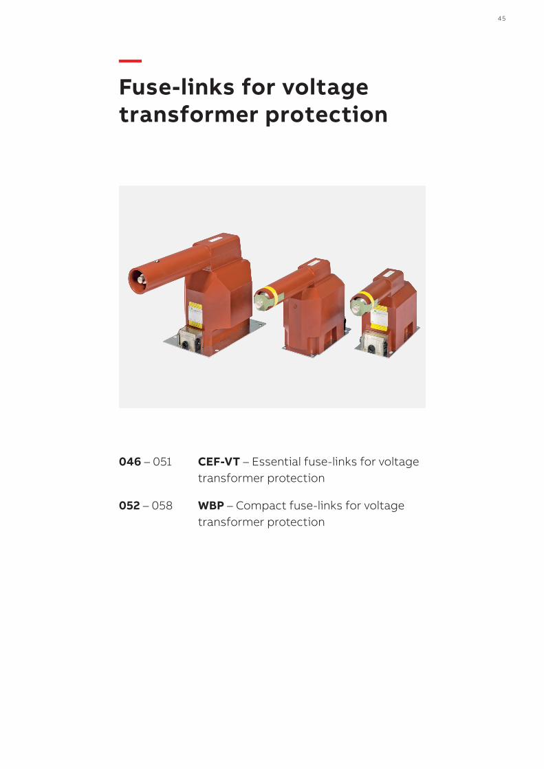
046 – 051 CEF-VT
052 – 058 WBP
061 – 070 Fuse-bases and accessories
062 – 063 UCE-NI
064 – 066 BWMPNS and BWMPNW
067 – 069 PBPM
070 – 074 Accessories
4 MEDIUM-VOLTAGE FUSES 3 KV– 40.5 KV, 0.5 A – 315 A
— General information
The main function of current limiting fuses is to protect electrical apparatus, such as distribution transformers, motors and capacitor banks against overload currents. Fuses can operate as sole devices or can be combined with air/SF6 insulated switch disconnectors. The choice depends on each application requirements and specific network conditions. One of the most critical factors for optimum protection is proper fuse selection. This can be done based on theoretical calculations but in many cases practical knowledge obtained from actual test results could make it easier and even more reliable. ABB, with its extensive apparatus product portfolio, has years of experience in this field. Our current limiting fuses have been designed to ensure safe operation in open air and for limited heat dissipation in installations such as gas insulated switchgears.Fuse selection principles for the most common situations are presented in the following pages together with common definitions. Moreover we offer our support for each specific case where presented criteria are not sufficient.
—DefinitionsCurrent limiting fuses
Current limiting fuse family is generally composed of three different fuse groups:• back-up fuses• general-purpose fuses• full-range fusesAll of them limit the value of prospective short-circuit currents during the interruption process, thereby extending the life time of nearby installed electrical equipment. The main difference is in the minimum breaking current that characterizes the lowest fault current that the fuses are capable of interrupting. This value is generally highest for back-up fuses, slightly smaller for general-purpose fuses and smallest, with the value close to the minimum melting current, for full-range fuses. But reaction time is critical for the
protection function. That is why back-up fuses, with an interruption time for the minimum breaking current in the range of a few seconds down to a few tens of milliseconds, are the most commonly used. The total clearing time in cases of high short-circuit currents is even shorter i.e. only a few milliseconds. That is why back-up fuses can be used as typical overload protection elements. General-purpose and full-range fuses capable of interrupting even the smallest values of currents can only be considered as over current devices since the interruption time is greater than one hour. Therefore, these types are used rarely and are usually recognized as a separate element of protection, without any linkage to the opening function of load break switch. ABB current limiting fuses have low minimum breaking currents, i.e. close to three times the rated current Ir.
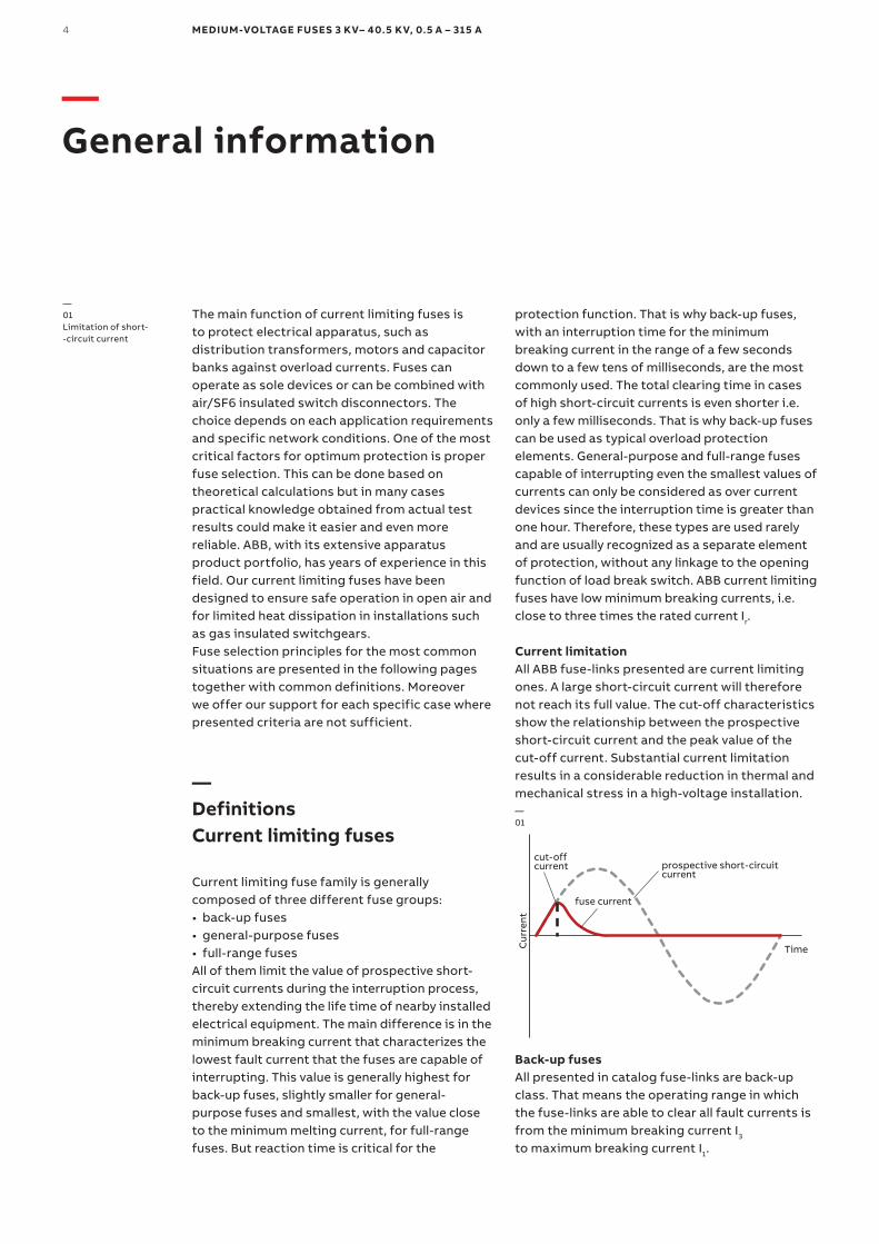
Current limitationAll ABB fuse-links presented are current limiting ones. A large short-circuit current will therefore not reach its full value. The cut-off characteristics show the relationship between the prospectiveshort-circuit current and the peak value of the cut-off current. Substantial current limitation results in a considerable reduction in thermal and mechanical stress in a high-voltage installation.—01
Cur
rent
Time
fuse current
cut-offcurrent prospective short-circuit
current
Back-up fusesAll presented in catalog fuse-links are back-up class. That means the operating range in which the fuse-links are able to clear all fault currents is from the minimum breaking current I3 to maximum breaking current I1.
—01Limitation of short- -circuit current
DISTRIBUTION SOLUTIONS 5
—02NALF – switch-fuse combination
—03TCU operation diagram
Switch-fuse combinationBack-up fuses are commonly used in switch-fuse combinations, both in open air and in gas insulated panels. When a switch-fuse combination operated as a protective device by tripping a system, the fuse assumes two different functions depending on the interrupted current value. When the fault current is greater than the transfer current, the fuse simply extends the breaking capability of the switch ending the interruption operation faster than the incorporated switch. This happens when the fuse clearing time is shorter than the total opening time of the Load Break Switch (LBS). By the time the striker pin pops up, the fuse has already cleared the fault current and the switch opens in almost no load conditions. If the fault currents are less than the nominal transfer current, the fuse then uses the striker pin to activate the switch, which in turn causes the system to trip. In other words, the interruption process is completed by the switch to prevent overloading of the fuses in situations where the fault current is low. Fuses used in switch-fuse combinations have to fulfill conditions specified in IEC 62271-105 (former IEC 60420 and IEC 420). Back-up fuses are specially designed for such application. The use of general-purpose or full-range fuses in switch-fuse combinations are not reasonable due to coordination principles.—02
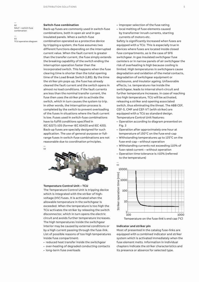
Temperature Control Unit – TCUThe Temperature Control Unit is tripping device which is integrated with the striker of high-voltage (HV) fuses. It is activated when the allowable temperature in the switchgear is exceeded. When the temperature is too high the TCU activates the striker by releasing the switch disconnector, which in turn opens the electric circuit and avoids further temperature increases. The high temperatures inside the switchgear interior may be caused by external conditions or by a high current passing through the fuse-link. List of possible reasons of too high temperatures inside fuse compartment:• reduced heat transfer inside the switchgear• over-heating of degraded conducting contacts• long-term fuse overloads
• improper selection of the fuse rating• local melting of fuse elements caused
by transformer inrush currents, starting currents of motors etc.
Safety is significantly increased when fuses are equipped with a TCU. This is especially true in devices where fuses are located inside closed fuse compartments, as is the case of SF6 switchgear. In gas insulated switchgear fuse canisters or in narrow panels of air switchgear the risk of overheating is high because cooling is limited. High temperatures in switchgears cause degradation and oxidation of the metal contacts, degradation of switchgear equipment or enclosures, and insulator ageing. Unfavorable effects, i.e. temperature rise inside the switchgear, leads to internal short-circuit and further temperature increases. In case of reaching too high temperature, TCU will be activated, releasing a striker and opening associated switch, thus eliminating the threat. The ABB CEF, CEF-S, CMF and CEF-VT (with striker) are equipped with a TCU as standard design.Temperature Control Unit features:• Operation according to diagram presented on
Fig. 3• Operation after approximately one hour at
temperature of 150°C on the fuse end-cap• Withstanding temperatures up to 125°C on the
fuse end-cap – without operation• Withstanding currents not exceeding 110% of
fuse rated current – without operation• Operation time tolerance is ±10% (referred
to the temperature)—03
10000
1000
100
100 1000Temperature on the fuse-link’s end cap [°C]
Stri
ker
op
erat
ion
tim
e [m
in]
10
1
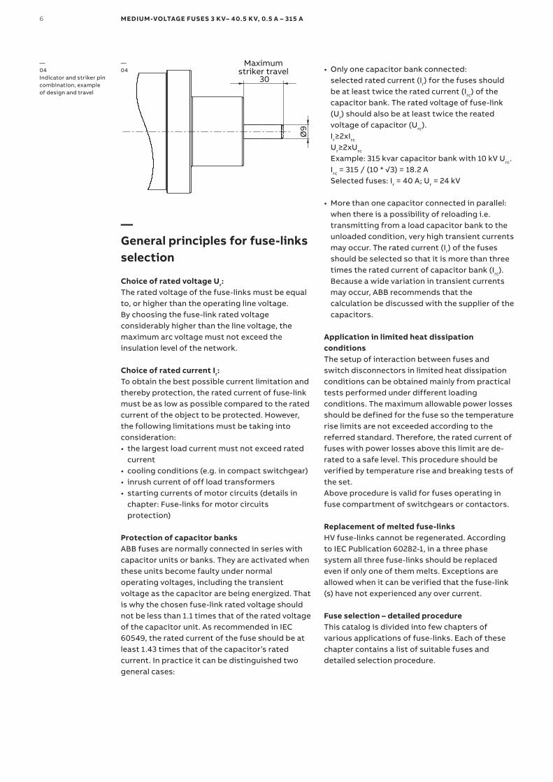
Indicator and striker pinMost of presented in the catalog fuse-links are equipped with a combined indicator and striker system which is activated immediately when the fuse element melts. Information in individual chapters indicate the striker characteristics and its presence or absence for selected type.
6 MEDIUM-VOLTAGE FUSES 3 KV– 40.5 KV, 0.5 A – 315 A
—04
Ø9
30
Maximumstriker travel
—General principles for fuse-links selection
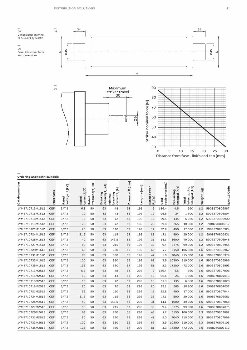
Choice of rated voltage Ur:The rated voltage of the fuse-links must be equal to, or higher than the operating line voltage. By choosing the fuse-link rated voltage considerably higher than the line voltage, the maximum arc voltage must not exceed the insulation level of the network.
Choice of rated current Ir:To obtain the best possible current limitation and thereby protection, the rated current of fuse-link must be as low as possible compared to the rated current of the object to be protected. However, the following limitations must be taking into consideration:• the largest load current must not exceed rated
current• cooling conditions (e.g. in compact switchgear)• inrush current of off load transformers• starting currents of motor circuits (details in
chapter: Fuse-links for motor circuits protection)
Protection of capacitor banksABB fuses are normally connected in series with capacitor units or banks. They are activated when these units become faulty under normal operating voltages, including the transient voltage as the capacitor are being energized. That is why the chosen fuse-link rated voltage should not be less than 1.1 times that of the rated voltage of the capacitor unit. As recommended in IEC 60549, the rated current of the fuse should be at least 1.43 times that of the capacitor’s rated current. In practice it can be distinguished two general cases:
—04Indicator and striker pin combination, example of design and travel
• Only one capacitor bank connected:selected rated current (Ir) for the fuses should be at least twice the rated current (Irc) of the capacitor bank. The rated voltage of fuse-link (Ur) should also be at least twice the reated voltage of capacitor (Urc).Ir≥2xIrc
Ur≥2xUrc
Example: 315 kvar capacitor bank with 10 kV Urc.Irc = 315 / (10 * √3) = 18.2 A Selected fuses: Ir = 40 A; Ur = 24 kV
• More than one capacitor connected in parallel:when there is a possibility of reloading i.e. transmitting from a load capacitor bank to the unloaded condition, very high transient currents may occur. The rated current (Ir) of the fuses should be selected so that it is more than three times the rated current of capacitor bank (Irc). Because a wide variation in transient currents may occur, ABB recommends that the calculation be discussed with the supplier of the capacitors.
Application in limited heat dissipation conditionsThe setup of interaction between fuses and switch disconnectors in limited heat dissipation conditions can be obtained mainly from practical tests performed under different loading conditions. The maximum allowable power losses should be defined for the fuse so the temperature rise limits are not exceeded according to the referred standard. Therefore, the rated current of fuses with power losses above this limit are de-rated to a safe level. This procedure should be verified by temperature rise and breaking tests of the set.Above procedure is valid for fuses operating in fuse compartment of switchgears or contactors.
Replacement of melted fuse-linksHV fuse-links cannot be regenerated. According to IEC Publication 60282-1, in a three phase system all three fuse-links should be replaced even if only one of them melts. Exceptions are allowed when it can be verified that the fuse-link (s) have not experienced any over current.
Fuse selection – detailed procedureThis catalog is divided into few chapters of various applications of fuse-links. Each of these chapter contains a list of suitable fuses and detailed selection procedure.
DISTRIBUTION SOLUTIONS 7
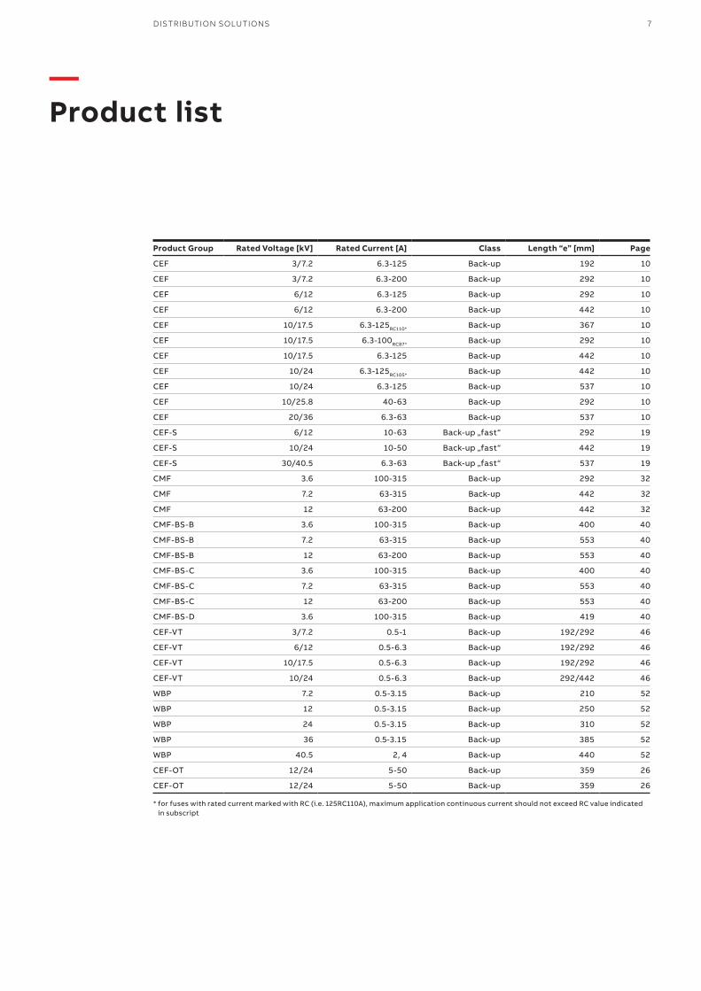
— Product list
Product Group Rated Voltage [kV] Rated Current [A] Class Length “e” [mm] Page
CEF 3/7.2 6.3-125 Back-up 192 10
CEF 3/7.2 6.3-200 Back-up 292 10
CEF 6/12 6.3-125 Back-up 292 10
CEF 6/12 6.3-200 Back-up 442 10
CEF 10/17.5 6.3-125RC110* Back-up 367 10
CEF 10/17.5 6.3-100RC87* Back-up 292 10
CEF 10/17.5 6.3-125 Back-up 442 10
CEF 10/24 6.3-125RC105* Back-up 442 10
CEF 10/24 6.3-125 Back-up 537 10
CEF 10/25.8 40-63 Back-up 292 10
CEF 20/36 6.3-63 Back-up 537 10
CEF-S 6/12 10-63 Back-up „fast“ 292 19
CEF-S 10/24 10-50 Back-up „fast“ 442 19
CEF-S 30/40.5 6.3-63 Back-up „fast“ 537 19
CMF 3.6 100-315 Back-up 292 32
CMF 7.2 63-315 Back-up 442 32
CMF 12 63-200 Back-up 442 32
CMF-BS-B 3.6 100-315 Back-up 400 40
CMF-BS-B 7.2 63-315 Back-up 553 40
CMF-BS-B 12 63-200 Back-up 553 40
CMF-BS-C 3.6 100-315 Back-up 400 40
CMF-BS-C 7.2 63-315 Back-up 553 40
CMF-BS-C 12 63-200 Back-up 553 40
CMF-BS-D 3.6 100-315 Back-up 419 40
CEF-VT 3/7.2 0.5-1 Back-up 192/292 46
CEF-VT 6/12 0.5-6.3 Back-up 192/292 46
CEF-VT 10/17.5 0.5-6.3 Back-up 192/292 46
CEF-VT 10/24 0.5-6.3 Back-up 292/442 46
WBP 7.2 0.5-3.15 Back-up 210 52
WBP 12 0.5-3.15 Back-up 250 52
WBP 24 0.5-3.15 Back-up 310 52
WBP 36 0.5-3.15 Back-up 385 52
WBP 40.5 2, 4 Back-up 440 52
CEF-OT 12/24 5-50 Back-up 359 26
CEF-OT 12/24 5-50 Back-up 359 26
* for fuses with rated current marked with RC (i.e. 125RC110A), maximum application continuous current should not exceed RC value indicated in subscript

8 MEDIUM-VOLTAGE FUSES 3 KV– 40.5 KV, 0.4 A – 315 A
DISTRIBUTION SOLUTIONS 9
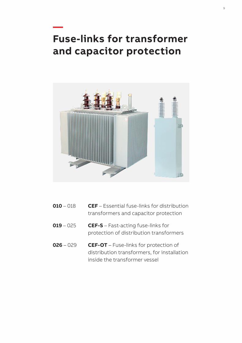
— Fuse-links for transformer and capacitor protection
010 – 018 CEF – Essential fuse-links for distribution transformers and capacitor protection
019 – 025 CEF-S – Fast-acting fuse-links for protection of distribution transformers
026 – 029 CEF-OT – Fuse-links for protection of distribution transformers, for installation inside the transformer vessel
10 CEF – FUSE-LINKS FOR TRANSFORMER AND CAPACITOR PROTECTION
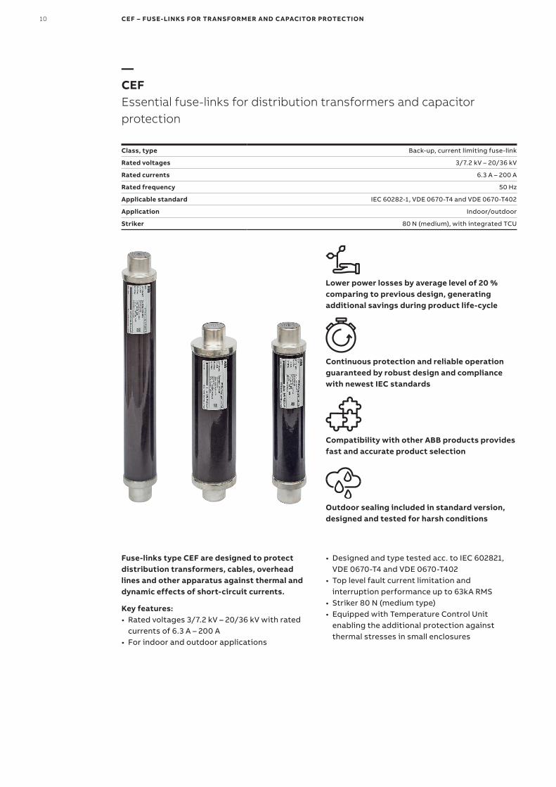
—CEFEssential fuse-links for distribution transformers and capacitor protection
Class, type Back-up, current limiting fuse-link
Rated voltages 3/7.2 kV – 20/36 kV
Rated currents 6.3 A – 200 A
Rated frequency 50 Hz
Applicable standard IEC 60282-1, VDE 0670-T4 and VDE 0670-T402
Application Indoor/outdoor
Striker 80 N (medium), with integrated TCU
Fuse-links type CEF are designed to protect distribution transformers, cables, overhead lines and other apparatus against thermal and dynamic effects of short-circuit currents.
Lower power losses by average level of 20 % comparing to previous design, generating additional savings during product life-cycle
Continuous protection and reliable operation guaranteed by robust design and compliance with newest IEC standards
Compatibility with other ABB products provides fast and accurate product selection
Outdoor sealing included in standard version, designed and tested for harsh conditions
Key features:• Rated voltages 3/7.2 kV – 20/36 kV with rated
currents of 6.3 A – 200 A • For indoor and outdoor applications
• Designed and type tested acc. to IEC 602821, VDE 0670-T4 and VDE 0670-T402
• Top level fault current limitation and interruption performance up to 63kA RMS
• Striker 80 N (medium type)• Equipped with Temperature Control Unit
enabling the additional protection against thermal stresses in small enclosures
DISTRIBUTION SOLUTIONS 11
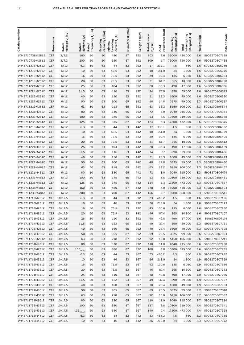
—Ordering and technical table
Cat
alo
g nu
mb
er
Fuse
nam
e
Rat
ed
volt
age
Ur [
kV]
Rat
ed
curr
ent
I r [A
]
Rat
ed
freq
uenc
y f r [
Hz]
Bre
akin
g
capa
city
I 1 [kA
]
Min
imal
b
reak
ing
curr
ent
I 3 [A
]
Dia
met
er D
[mm
]
Leng
th e
[mm
]
Rat
ed p
ower
P
w [
W]
Co
ld
resi
stan
ce [m
Ω]
Pre-
arci
ng
inte
gra
l [A
2 s]
Tota
l in
terr
upti
ng
inte
gra
l [A
2 s]
Wei
ght
[kg
]
EA
N 1
3 C
od
e
1YMB710713M1512 CEF 3/7.2 6.3 50 63 48 53 192 9 186.4 4.5 560 1.2 5908270806887
1YMB710716M1512 CEF 3/7.2 10 50 63 43 53 192 12 96.6 24 1 800 1.2 5908270806894
1YMB710718M1512 CEF 3/7.2 16 50 63 72 53 192 18 59.5 135 6 060 1.2 5908270806900
1YMB710719M1512 CEF 3/7.2 20 50 63 72 53 192 20 39.8 265 10 300 1.2 5908270806917
1YMB710721M1512 CEF 3/7.2 25 50 63 110 53 192 17 22.8 490 17 000 1.2 5908270806924
1YMB710724M1512 CEF 3/7.2 31.5 50 63 115 53 192 23 17.1 890 29 000 1.2 5908270806931
1YMB710725M1512 CEF 3/7.2 40 50 63 143.5 53 192 31 14.1 1600 49 000 1.2 5908270806948
1YMB710727M1512 CEF 3/7.2 50 50 63 215 53 192 32 9.4 3375 99 000 1.2 5908270806955
1YMB710729M1612 CEF 3/7.2 63 50 63 220 65 192 43 7.7 5150 106 000 1.6 5908270806962
1YMB710731M1612 CEF 3/7.2 80 50 63 320 65 192 47 5.0 7040 215 000 1.6 5908270806979
1YMB710733M1612 CEF 3/7.2 100 50 63 380 65 192 62 3.9 10300 319 000 1.6 5908270806986
1YMB710735M1812 CEF 3/7.2 125 50 63 380 87 192 81 3.3 17200 472 000 2.6 5908270806993
1YMB710713M2512 CEF 3/7.2 6.3 50 63 48 53 292 9 186.4 4.5 560 1.6 5908270807006
1YMB710716M2512 CEF 3/7.2 10 50 63 43 53 292 12 96.6 24 1 800 1.6 5908270807013
1YMB710718M2512 CEF 3/7.2 16 50 63 72 53 292 18 57.3 135 6 060 1.6 5908270807020
1YMB710719M2512 CEF 3/7.2 20 50 63 72 53 292 20 39.1 265 10 300 1.6 5908270807037
1YMB710721M2512 CEF 3/7.2 25 50 63 110 53 292 17 22.8 490 17 000 1.6 5908270807044
1YMB710724M2512 CEF 3/7.2 31.5 50 63 115 53 292 23 17.1 890 29 000 1.6 5908270807051
1YMB710725M2512 CEF 3/7.2 40 50 63 143.5 53 292 31 14.1 1600 49 000 1.6 5908270807068
1YMB710727M2512 CEF 3/7.2 50 50 63 215 53 292 32 9.4 3375 99 000 1.6 5908270807075
1YMB710729M2612 CEF 3/7.2 63 50 63 220 65 292 43 7.7 5150 106 000 2.3 5908270807082
1YMB710731M2612 CEF 3/7.2 80 50 63 320 65 292 47 5.0 7040 215 000 2.3 5908270807099
1YMB710733M2612 CEF 3/7.2 100 50 63 380 65 292 62 3.9 10300 319 000 2.3 5908270807105
1YMB710735M2812 CEF 3/7.2 125 50 63 380 87 292 81 3.3 17200 472 000 3.6 5908270807112
34 34
e
D D
Ø45
Ø45
—05Dimensional drawing of fuse-link type CEF
—05
Ø9
30
Maximumstriker travel
30
40
50
60
70
80
90
0 5 10 15 20 25 30
Stri
ker
nom
inal
fo
rce
[N]
Distance from fuse - link's end cap [mm]
—06Fuse-link striker force and dimensions
—06
12 CEF – FUSE-LINKS FOR TRANSFORMER AND CAPACITOR PROTECTION
Cat
alo
g nu
mb
er
Fuse
nam
e
Rat
ed
volt
age
Ur [
kV]
Rat
ed
curr
ent
I r [A
]
Rat
ed
freq
uenc
y f r [
Hz]
Bre
akin
g
capa
city
I 1 [kA
]
Min
imal
b
reak
ing
curr
ent
I 3 [A
]
Dia
met
er D
[mm
]
Leng
th e
[mm
]
Rat
ed p
ower
P
w [
W]
Co
ld
resi
stan
ce [m
Ω]
Pre-
arci
ng
inte
gra
l [A
2 s]
Tota
l in
terr
upti
ng
inte
gra
l [A
2 s]
Wei
ght
[kg
]
EA
N 1
3 C
od
e
1YMB710738M2812 CEF 3/7.2 160 50 50 480 87 292 103 2.6 35000 430 000 3.6 5908270807129
1YMB710739M2812 CEF 3/7.2 200 50 50 650 87 292 109 1.7 76000 750 000 3.6 5908270807488
1YMB711213M2512 CEF 6/12 6.3 50 63 44 53 292 17 332.1 4.5 560 1.6 5908270806269
1YMB711216M2512 CEF 6/12 10 50 63 43.5 53 292 18 151.0 24 1 800 1.6 5908270806276
1YMB711218M2512 CEF 6/12 16 50 63 72.5 53 292 29 90.4 135 6 060 1.6 5908270806283
1YMB711219M2512 CEF 6/12 20 50 63 72.5 53 292 31 61.7 265 10 300 1.6 5908270806290
1YMB711221M2512 CEF 6/12 25 50 63 104 53 292 28 35.3 490 17 000 1.6 5908270806306
1YMB711224M2512 CEF 6/12 31.5 50 63 116 53 292 34 27.0 890 29 000 1.6 5908270806313
1YMB711225M2512 CEF 6/12 40 50 63 150 53 292 51 22.3 1600 49 000 1.6 5908270806320
1YMB711227M2612 CEF 6/12 50 50 63 200 65 292 48 14.8 3375 99 000 2.3 5908270806337
1YMB711229M2612 CEF 6/12 63 50 63 218 65 292 63 12.2 5150 106 000 2.3 5908270806344
1YMB711231M2612 CEF 6/12 80 50 63 330 65 292 72 8.0 7040 215 000 2.3 5908270806351
1YMB711233M2612 CEF 6/12 100 50 63 375 65 292 93 6.5 10300 319 000 2.3 5908270806368
1YMB711235M2812 CEF 6/12 125 50 63 375 87 292 124 5.3 17200 472 000 3.6 5908270806375
1YMB711213M4512 CEF 6/12 6.3 50 63 44 53 442 17 332.1 4.5 560 2.3 5908270806382
1YMB711216M4512 CEF 6/12 10 50 63 43.5 53 442 18 151.0 24 1 800 2.3 5908270806399
1YMB711218M4512 CEF 6/12 16 50 63 72.5 53 442 29 90.4 135 6 060 2.3 5908270806405
1YMB711219M4512 CEF 6/12 20 50 63 72.5 53 442 31 61.7 265 10 300 2.3 5908270806412
1YMB711221M4512 CEF 6/12 25 50 63 104 53 442 28 35.3 490 17 000 2.3 5908270806429
1YMB711224M4512 CEF 6/12 31.5 50 63 116 53 442 34 27 890 29 000 2.3 5908270806436
1YMB711225M4512 CEF 6/12 40 50 63 150 53 442 51 22.3 1600 49 000 2.3 5908270806443
1YMB711227M4612 CEF 6/12 50 50 63 200 65 442 48 14.8 3375 99 000 3.3 5908270806450
1YMB711229M4612 CEF 6/12 63 50 63 218 65 442 63 12.2 5150 106 000 3.3 5908270806467
1YMB711231M4612 CEF 6/12 80 50 63 330 65 442 72 8.0 7040 215 000 3.3 5908270806474
1YMB711233M4612 CEF 6/12 100 50 63 375 65 442 93 6.5 10300 319 000 3.3 5908270806481
1YMB711235M4612 CEF 6/12 125 50 63 375 65 442 124 5.3 17200 472 000 3.3 5908270807877
1YMB711238M4812 CEF 6/12 160 50 63 480 87 442 170 4.0 35000 430 000 5.3 5908270806504
1YMB711239M4812 CEF 6/12 200 50 63 700 87 442 166 2.7 90000 860 000 5.3 5908270806511
1YMB711713M2512 CEF 10/17.5 6.3 50 63 44 53 292 23 465.2 4.5 560 1.6 5908270807136
1YMB711716M2512 CEF 10/17.5 10 50 63 46 53 292 26 213.0 24 1 800 1.6 5908270807143
1YMB711718M2512 CEF 10/17.5 16 50 63 76.5 53 292 43 130.6 135 6 060 1.6 5908270807150
1YMB711719M2512 CEF 10/17.5 20 50 63 76.5 53 292 46 87.4 265 10 300 1.6 5908270807167
1YMB711721M2512 CEF 10/17.5 25 50 63 110 53 292 40 49.8 490 17 000 1.6 5908270807174
1YMB711724M2612 CEF 10/17.5 31.5 50 63 122 65 292 49 37.4 890 29 000 2.3 5908270807181
1YMB711725M2612 CEF 10/17.5 40 50 63 160 65 292 70 28.4 1600 49 000 2.3 5908270807198
1YMB711727M2812 CEF 10/17.5 50 50 63 205 87 292 69 20.5 3375 99 000 3.6 5908270807204
1YMB711729M2812 CEF 10/17.5 63 50 63 218 87 292 92 16.8 5150 106 000 3.6 5908270807211
1YMB711731M2812 CEF 10/17.5 80 50 63 330 87 292 110 11.0 7040 215 000 3.6 5908270807228
1YMB711733M2812 CEF 10/17.5 100RC87 50 63 380 87 292 100 8.8 10300 319 000 3.6 5908270807235
1YMB711713M3512 CEF 10/17.5 6.3 50 63 44 53 367 23 465.2 4.5 560 1.9 5908270807242
1YMB711716M3512 CEF 10/17.5 10 50 63 46 53 367 26 213.0 24 1 800 1.9 5908270807259
1YMB711718M3512 CEF 10/17.5 16 50 63 76.5 53 367 43 130.6 135 6 060 1.9 5908270807266
1YMB711719M3512 CEF 10/17.5 20 50 63 76.5 53 367 46 87.4 265 10 300 1.9 5908270807273
1YMB711721M3512 CEF 10/17.5 25 50 63 110 53 367 40 49.8 490 17 000 1.9 5908270807280
1YMB711724M3512 CEF 10/17.5 31.5 50 63 122 53 367 49 37.4 890 29 000 1.9 5908270807297
1YMB711725M3512 CEF 10/17.5 40 50 63 160 53 367 70 28.4 1600 49 000 1.9 5908270807303
1YMB711727M3612 CEF 10/17.5 50 50 63 205 65 367 69 20.5 3375 99 000 2.7 5908270807310
1YMB711729M3612 CEF 10/17.5 63 50 63 218 65 367 92 16.8 5150 106 000 2.7 5908270807327
1YMB711731M3612 CEF 10/17.5 80 50 63 330 65 367 110 11.0 7040 215 000 2.7 5908270807334
1YMB711733M3812 CEF 10/17.5 100 50 63 380 87 367 137 8.8 10300 319 000 4.4 5908270807341
1YMB711735M3812 CEF 10/17.5 125RC110 50 63 380 87 367 140 7.4 17200 472 000 4.4 5908270807358
1YMB711713M4512 CEF 10/17.5 6.3 50 63 44 53 442 23 465.2 4.5 560 2.3 5908270807365
1YMB711716M4512 CEF 10/17.5 10 50 63 46 53 442 26 213.0 24 1 800 2.3 5908270807372
DISTRIBUTION SOLUTIONS 13
Cat
alo
g nu
mb
er
Fuse
nam
e
Rat
ed
volt
age
Ur [
kV]
Rat
ed
curr
ent
I r [A
]
Rat
ed
freq
uenc
y f r [
Hz]
Bre
akin
g
capa
city
I 1 [kA
]
Min
imal
b
reak
ing
curr
ent
I 3 [A
]
Dia
met
er D
[mm
]
Leng
th e
[mm
]
Rat
ed p
ower
P
w [
W]
Co
ld
resi
stan
ce [m
Ω]
Pre-
arci
ng
inte
gra
l [A
2 s]
Tota
l in
terr
upti
ng
inte
gra
l [A
2 s]
Wei
ght
[kg
]
EA
N 1
3 C
od
e
1YMB711718M4512 CEF 10/17.5 16 50 63 76.5 53 442 43 130.6 135 6 060 2.3 5908270807389
1YMB711719M4512 CEF 10/17.5 20 50 63 76.5 53 442 46 87.4 265 10 300 2.3 5908270807396
1YMB711721M4512 CEF 10/17.5 25 50 63 110 53 442 40 49.8 490 17 000 2.3 5908270807402
1YMB711724M4512 CEF 10/17.5 31.5 50 63 122 53 442 49 37.4 890 29 000 2.3 5908270807419
1YMB711725M4512 CEF 10/17.5 40 50 63 160 53 442 70 28.4 1600 49 000 2.3 5908270807426
1YMB711727M4612 CEF 10/17.5 50 50 63 205 65 442 69 20.5 3375 99 000 3.3 5908270807433
1YMB711729M4612 CEF 10/17.5 63 50 63 218 65 442 92 16.8 5150 106 000 3.3 5908270807440
1YMB711731M4612 CEF 10/17.5 80 50 63 330 65 442 110 11.2 7040 215 000 3.3 5908270807457
1YMB711733M4612 CEF 10/17.5 100 50 63 380 65 442 136 8.5 10300 319 000 3.3 5908270807464
1YMB711735M4812 CEF 10/17.5 125 50 63 380 87 442 183 7.4 17200 472 000 5.3 5908270807471
1YMB712413M4512 CEF 10/24 6.3 50 63 43 53 442 28 572.6 4.5 560 2.3 5908270806542
1YMB712416M4512 CEF 10/24 10 50 63 46 53 442 33 272.2 24 1 800 2.3 5908270806559
1YMB712418M4512 CEF 10/24 16 50 63 76.5 53 442 55 168.9 135 6 060 2.3 5908270806566
1YMB712419M4512 CEF 10/24 20 50 63 76.5 53 442 59 112.5 265 10 300 2.3 5908270806573
1YMB712421M4512 CEF 10/24 25 50 63 110 53 442 57 64.8 490 17 000 2.3 5908270806580
1YMB712424M4512 CEF 10/24 31.5 50 63 122 53 442 65 48.9 890 29 000 2.3 5908270806597
1YMB712425M4512 CEF 10/24 40 50 63 160 53 442 89 40.2 1600 49 000 2.3 5908270806603
1YMB712427M4612 CEF 10/24 50 50 63 205 65 442 92 27.0 3375 99 000 3.3 5908270806610
1YMB712429M4612 CEF 10/24 63 50 63 215 65 442 127 21.9 5150 106 000 3.3 5908270806627
1YMB712431M4612 CEF 10/24 80 50 63 325 65 442 152 15.6 7040 215 000 3.3 5908270806634
1YMB712433M4812 CEF 10/24 100 50 63 375 87 442 200 12.9 10300 319 000 5.3 5908270806641
1YMB712435M4812 CEF 10/24 125RC105 50 40 380 87 442 173 10.5 17200 472 000 5.3 5908270807860
1YMB712413M5512 CEF 10/24 6.3 50 63 43 53 537 28 572.6 4.5 560 3.1 5908270806672
1YMB712416M5512 CEF 10/24 10 50 63 46 53 537 33 272.2 24 1 800 3.1 5908270806689
1YMB712418M5512 CEF 10/24 16 50 63 76.5 53 537 55 168.9 135 6 060 3.1 5908270806696
1YMB712419M5512 CEF 10/24 20 50 63 76.5 53 537 59 112.5 265 10 300 3.1 5908270806702
1YMB712421M5512 CEF 10/24 25 50 63 110 53 537 57 64.8 490 17 000 3.1 5908270806719
1YMB712424M5512 CEF 10/24 31.5 50 63 122 53 537 65 48.9 890 29 000 3.1 5908270806726
1YMB712425M5512 CEF 10/24 40 50 63 160 53 537 89 40.2 1600 49 000 3.1 5908270806733
1YMB712427M5612 CEF 10/24 50 50 63 205 65 537 92 27.0 3375 99 000 3.9 5908270806740
1YMB712429M5612 CEF 10/24 63 50 63 215 65 537 127 21.9 5150 106 000 3.9 5908270806757
1YMB712431M5612 CEF 10/24 80 50 63 325 65 537 152 15.6 7040 215 000 3.9 5908270806764
1YMB712433M5812 CEF 10/24 100 50 63 375 87 537 200 12.9 10300 319 000 6.4 5908270806771
1YMB712435M5812 CEF 10/24 125 50 63 375 87 537 234 10.6 17200 472 000 6.4 5908270806788
1YMB712525M2811 CEF 10/25.8 40 50 16 119 87 292 91 40.2 1446 32 538 3.6 5908270806238
1YMB712527M2811 CEF 10/25.8 50 50 16 191 87 292 93 26 4339 85 791 3.6 5908270806245
1YMB712529M2811 CEF 10/25.8 63 50 16 278 87 292 97 17.2 8099 155 020 3.6 5908270806252
1YMB713613M5512 CEF 20/36 6.3 50 40 37 53 537 47 925.0 4.5 560 3.1 5908270806795
1YMB713616M5512 CEF 20/36 10 50 40 37.5 53 537 50 413.6 24 1 800 3.1 5908270806801
1YMB713618M5512 CEF 20/36 16 50 40 59 53 537 85 254.0 135 6 060 3.1 5908270806818
1YMB713619M5512 CEF 20/36 20 50 40 62.5 53 537 88 162.3 265 10 300 3.1 5908270806825
1YMB713621M5512 CEF 20/36 25 50 40 100 53 537 87 104.0 490 17 000 3.1 5908270806832
1YMB713624M5612 CEF 20/36 31.5 50 40 158 65 537 118 84.0 1050 20 700 3.9 5908270806849
1YMB713625M5612 CEF 20/36 40 50 40 164 65 537 135 57.7 1850 39 000 3.9 5908270806856
1YMB713627M5812 CEF 20/36 50 50 40 230 87 537 157 43.5 4040 99 600 6.4 5908270806863
1YMB713629M5812 CEF 20/36 63 50 40 299 87 537 225 36.6 5800 89 500 6.4 5908270806870
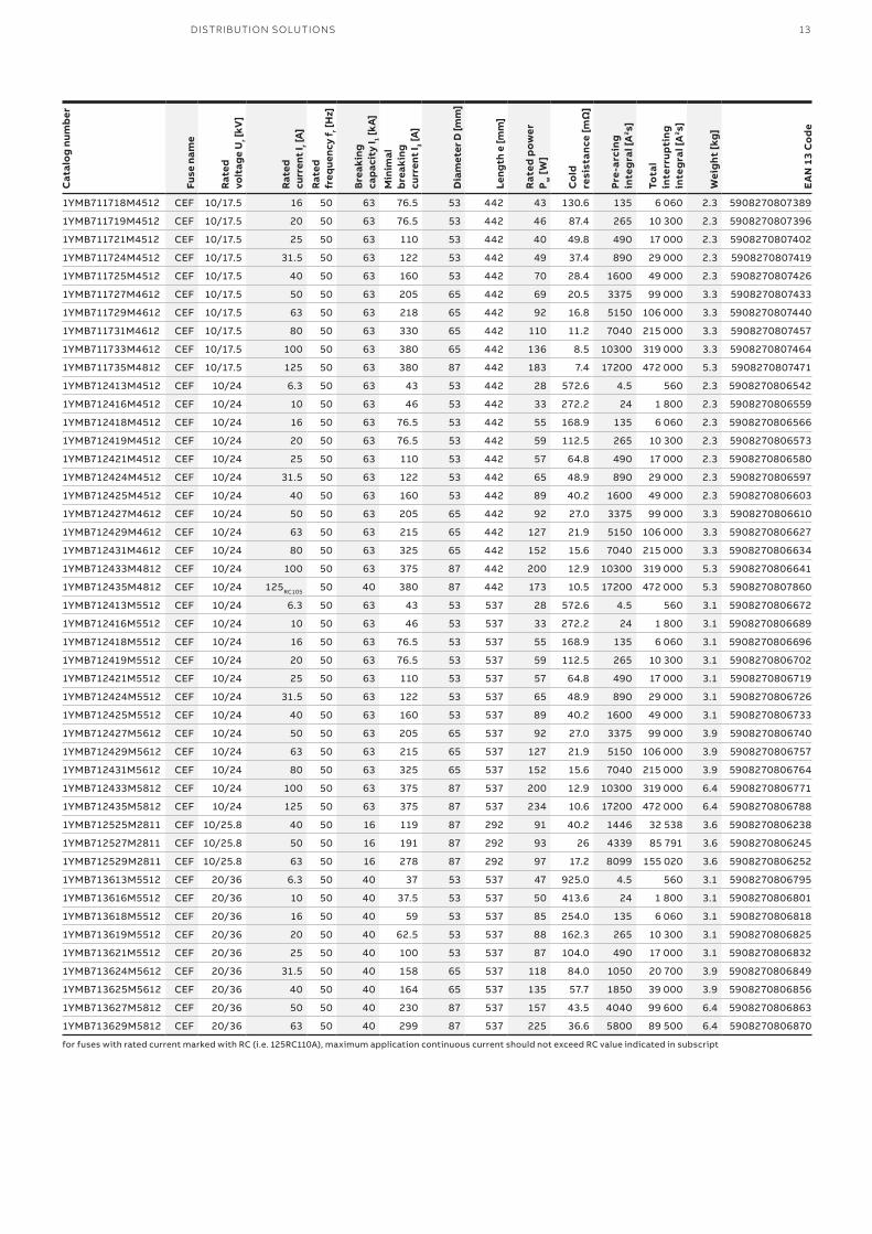
for fuses with rated current marked with RC (i.e. 125RC110A), maximum application continuous current should not exceed RC value indicated in subscript
14 CEF – FUSE-LINKS FOR TRANSFORMER AND CAPACITOR PROTECTION
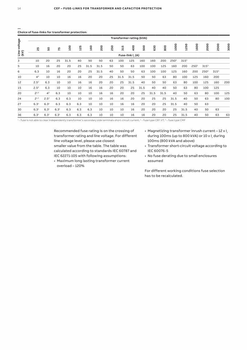
—Choice of fuse-links for transformer protection:
Line
vo
ltag
e (k
V)
Transformer rating (kVA)25 50 75 10
0
125
160
200
250
315
40
0
500
630
800
100
0
1250
160
0
200
0
250
0
300
0
Fuse-link Ir (A)
3 10 20 25 31.5 40 50 50 63 100 125 160 160 200 2503 3153
5 10 16 20 20 25 31.5 31.5 50 50 63 100 100 125 160 200 2503 3153
6 6.3 10 16 20 20 25 31.5 40 50 50 63 100 100 125 160 200 2503 3153
10 42 10 10 16 16 20 20 25 31.5 31.5 50 50 63 80 100 125 160 200
12 2.52 6.3 10 10 16 16 20 20 25 31.5 40 50 50 63 80 100 125 160 200
15 2.52 6.3 10 10 10 16 16 20 20 25 31.5 40 40 50 63 80 100 125
20 21,2 42 6.3 10 10 10 16 16 20 20 25 31.5 31.5 40 50 63 80 100 125
24 21,2 2.52 6.3 6.3 10 10 10 16 16 20 20 25 25 31.5 40 50 63 80 100
27 6.31 6.31 6.3 6.3 6.3 10 10 10 16 16 20 20 25 31.5 40 50 63
30 6.31 6.31 6.31 6.3 6.3 6.3 10 10 10 16 20 20 20 25 31.5 40 50 63
36 6.31 6.31 6.31 6.3 6.3 6.3 10 10 10 16 16 20 20 25 31.5 40 50 63 631 – fuse is not able to clear independently transformer’s secondary side terminals short-circuit current; 2 – fuse type CEF-VT; 3 – fuse type CMF
Recommended fuse rating is on the crossing of transformer rating and line voltage. For different line voltage level, please use closestsmaller value from the table. The table was calculated according to standards IEC 60787 and IEC 62271-105 with following assumptions:• Maximum long lasting transformer current
overload – 120%
• Magnetizing transformer inrush current – 12 x Ir during 100ms (up to 800 kVA) or 10 x Ir during 100ms (800 kVA and above)
• Transformer short-circuit voltage according to IEC 60076-5
• No fuse derating due to small enclosures assumed
For different working conditions fuse selection has to be recalculated.
DISTRIBUTION SOLUTIONS 15
1000
100
1
10
0.1
Pre-
arci
ng t
ime
[s]
Prospective current [A]
0.0110 100 1000 10000
6.3 A 10 A
16 A
20A
63A 100A 160A
125A 200A
40A
50A 80A
25A
31.5A
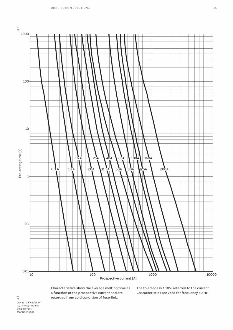
—07CEF 3/7.2 kV; 6/12 kV; 10/17.5 kV; 10/24 kV time-current characteristics
—07
Characteristics show the average melting time as a function of the prospective current and are recorded from cold condition of fuse-link.
The tolerance is ± 10% referred to the current. Characteristics are valid for frequency 50 Hz.
16 CEF – FUSE-LINKS FOR TRANSFORMER AND CAPACITOR PROTECTION
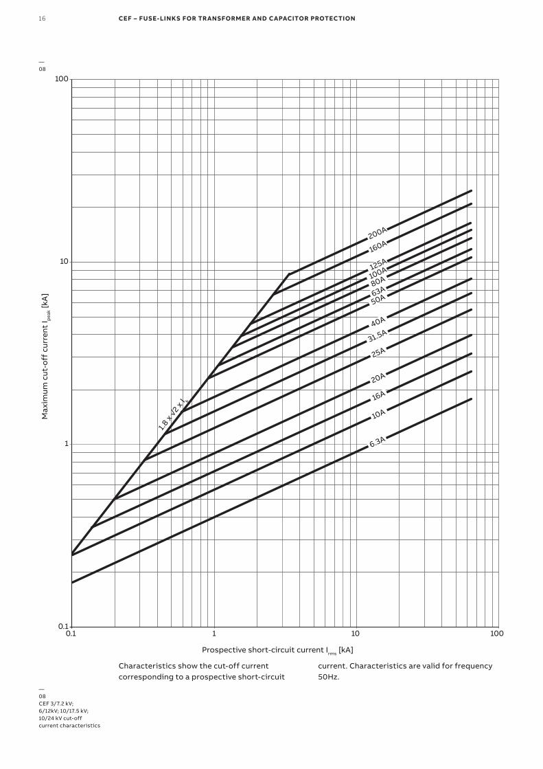
—08CEF 3/7.2 kV; 6/12kV; 10/17.5 kV; 10/24 kV cut-offcurrent characteristics
200A
160A
125A
100A
31.5A
80A
63A50A
40A
25A
20A
16A
10A
6.3A
1.8 x
√2 x
I k
100
10
1
0.10.1 1 10
Prospective short-circuit current Irms [kA]
Max
imum
cut
-off
cur
rent
I pea
k [kA
]
100
—08
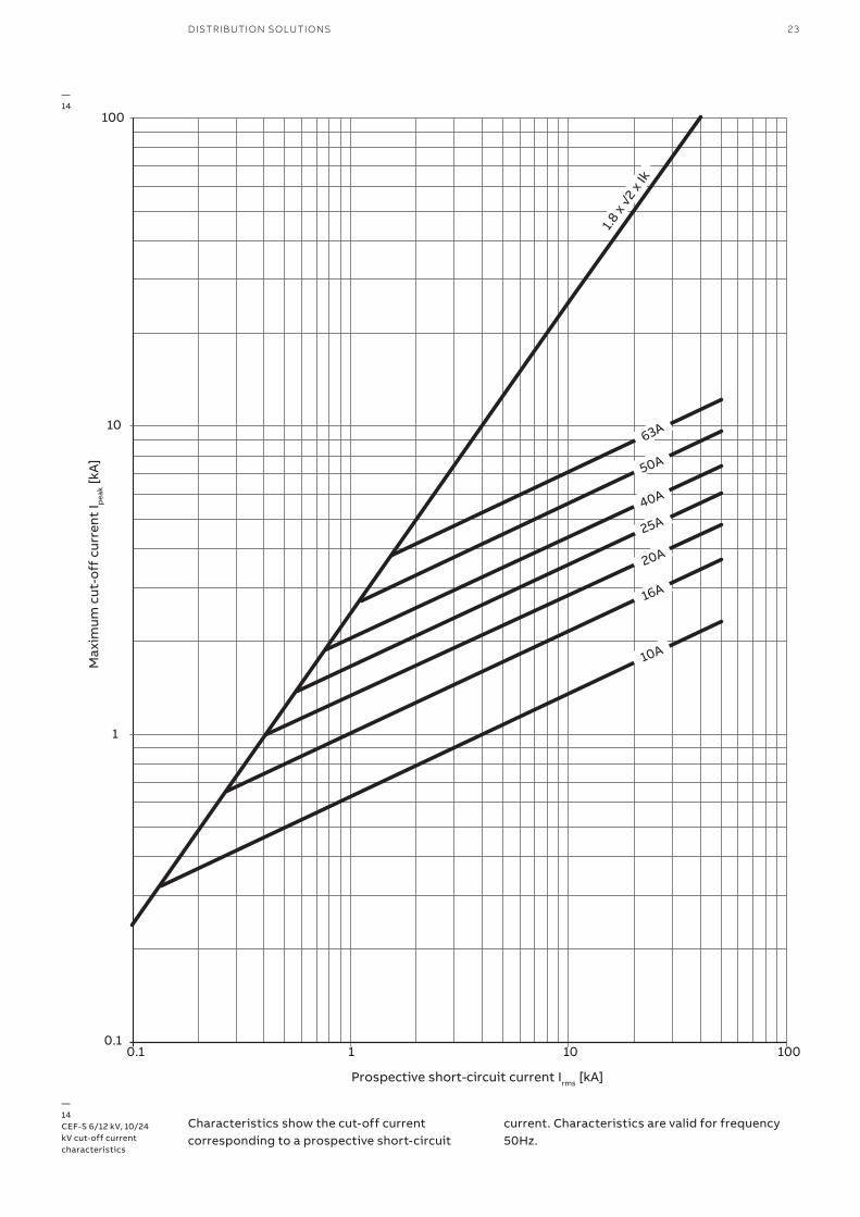
Characteristics show the cut-off current corresponding to a prospective short-circuit
current. Characteristics are valid for frequency 50Hz.
DISTRIBUTION SOLUTIONS 17
6.3 A 10 A
16 A
20A
63A40A
50A
25A
31.5A
1000
100
1
10
0.1
0.01
Pre-
arci
ng t
ime
[s]
Prospective current [A]
10 100 1000 10000
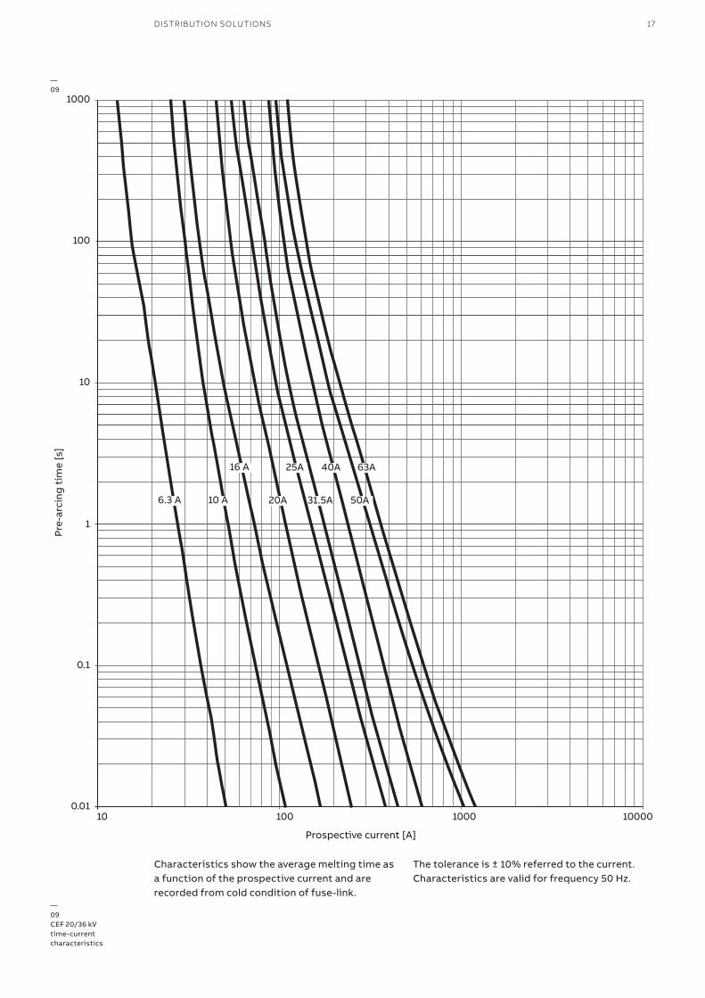
—09CEF 20/36 kV time-current characteristics
—09
Characteristics show the average melting time as a function of the prospective current and are recorded from cold condition of fuse-link.
The tolerance is ± 10% referred to the current. Characteristics are valid for frequency 50 Hz.
18 CEF – FUSE-LINKS FOR TRANSFORMER AND CAPACITOR PROTECTION
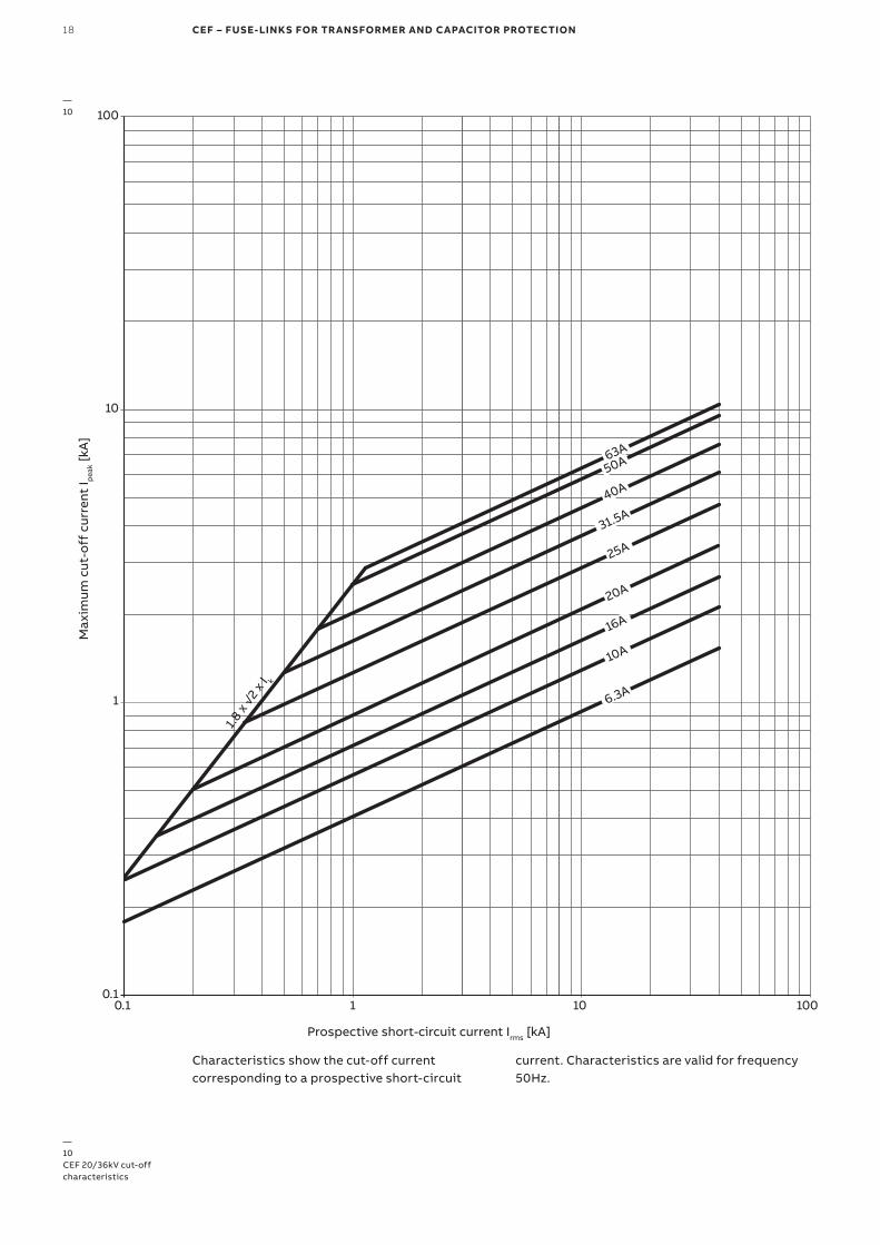
—10CEF 20/36kV cut-off characteristics
—10
31.5A
63A50A
40A
25A
20A
16A
10A
6.3A
1.8 x
√2 x
I k
100
10
1
0.10.1 1 10
Prospective short-circuit current Irms [kA]
Max
imum
cut
-off
cur
rent
I pea
k [kA
]
100
Characteristics show the cut-off current corresponding to a prospective short-circuit
current. Characteristics are valid for frequency 50Hz.
DISTRIBUTION SOLUTIONS 19
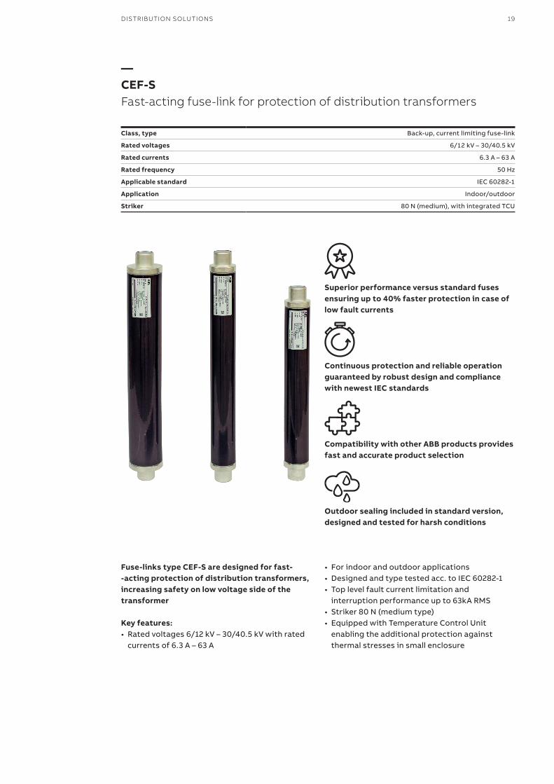
—CEF-SFast-acting fuse-link for protection of distribution transformers
Class, type Back-up, current limiting fuse-link
Rated voltages 6/12 kV – 30/40.5 kV
Rated currents 6.3 A – 63 A
Rated frequency 50 Hz
Applicable standard IEC 60282-1
Application Indoor/outdoor
Striker 80 N (medium), with integrated TCU
Superior performance versus standard fuses ensuring up to 40% faster protection in case of low fault currents
Continuous protection and reliable operation guaranteed by robust design and compliance with newest IEC standards
Compatibility with other ABB products provides fast and accurate product selection
Outdoor sealing included in standard version, designed and tested for harsh conditions
Fuse-links type CEF-S are designed for fast- -acting protection of distribution transformers, increasing safety on low voltage side of the transformer Key features:• Rated voltages 6/12 kV – 30/40.5 kV with rated
currents of 6.3 A – 63 A
• For indoor and outdoor applications• Designed and type tested acc. to IEC 60282-1• Top level fault current limitation and
interruption performance up to 63kA RMS• Striker 80 N (medium type)• Equipped with Temperature Control Unit
enabling the additional protection against thermal stresses in small enclosure
20 CEF-S – FUSE-LINKS FOR TRANSFORMER PROTECTION
34 34
e
D D
Ø45
Ø45
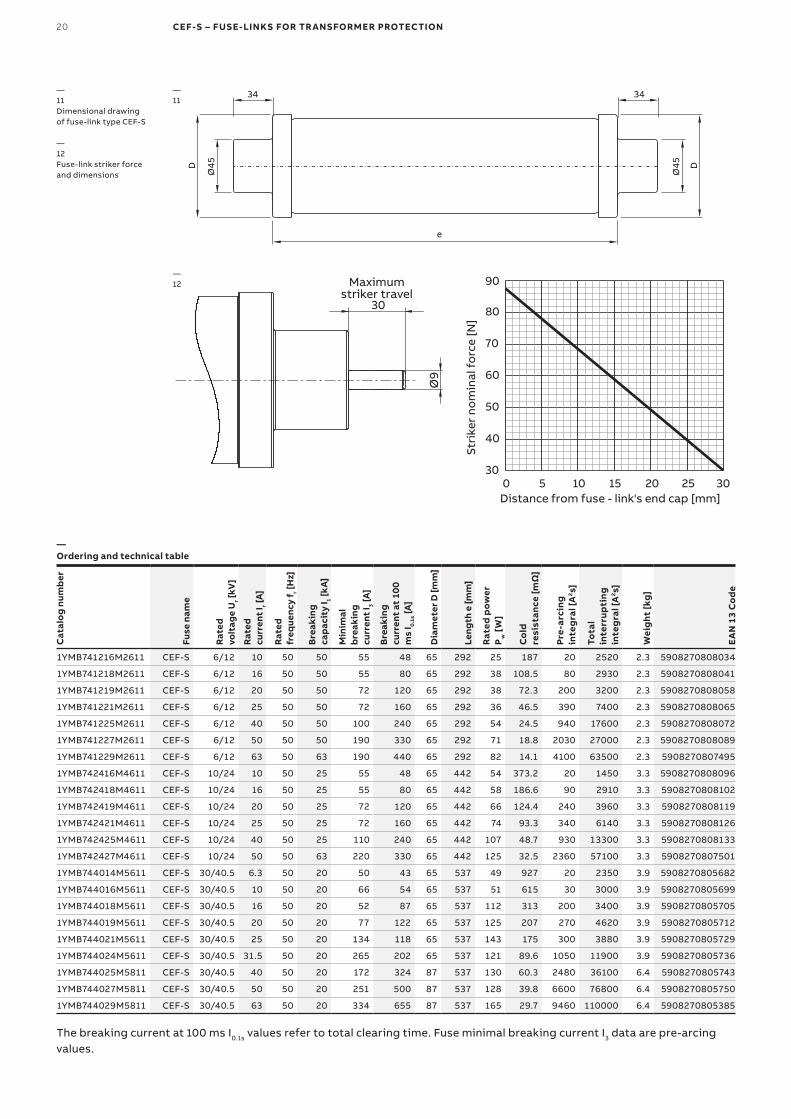
—11Dimensional drawing of fuse-link type CEF-S
—12Fuse-link striker force and dimensions
—11
—Ordering and technical table
Cat
alo
g nu
mb
er
Fuse
nam
e
Rat
ed
volt
age
Ur [
kV]
Rat
ed
curr
ent
I r [A
]
Rat
ed
freq
uenc
y f r [
Hz]
Bre
akin
g
capa
city
I 1 [kA
]
Min
imal
b
reak
ing
curr
ent
I 3 [A
]
Bre
akin
g
curr
ent
at 1
00
ms
I 0.1s
[A]
Dia
met
er D
[mm
]
Leng
th e
[mm
]
Rat
ed p
ower
P
w [
W]
Co
ld
resi
stan
ce [m
Ω]
Pre-
arci
ng
inte
gra
l [A
2 s]
Tota
l in
terr
upti
ng
inte
gra
l [A
2 s]
Wei
ght
[kg
]
EA
N 1
3 C
od
e
1YMB741216M2611 CEF-S 6/12 10 50 50 55 48 65 292 25 187 20 2520 2.3 5908270808034
1YMB741218M2611 CEF-S 6/12 16 50 50 55 80 65 292 38 108.5 80 2930 2.3 5908270808041
1YMB741219M2611 CEF-S 6/12 20 50 50 72 120 65 292 38 72.3 200 3200 2.3 5908270808058
1YMB741221M2611 CEF-S 6/12 25 50 50 72 160 65 292 36 46.5 390 7400 2.3 5908270808065
1YMB741225M2611 CEF-S 6/12 40 50 50 100 240 65 292 54 24.5 940 17600 2.3 5908270808072
1YMB741227M2611 CEF-S 6/12 50 50 50 190 330 65 292 71 18.8 2030 27000 2.3 5908270808089
1YMB741229M2611 CEF-S 6/12 63 50 63 190 440 65 292 82 14.1 4100 63500 2.3 5908270807495
1YMB742416M4611 CEF-S 10/24 10 50 25 55 48 65 442 54 373.2 20 1450 3.3 5908270808096
1YMB742418M4611 CEF-S 10/24 16 50 25 55 80 65 442 58 186.6 90 2910 3.3 5908270808102
1YMB742419M4611 CEF-S 10/24 20 50 25 72 120 65 442 66 124.4 240 3960 3.3 5908270808119
1YMB742421M4611 CEF-S 10/24 25 50 25 72 160 65 442 74 93.3 340 6140 3.3 5908270808126
1YMB742425M4611 CEF-S 10/24 40 50 25 110 240 65 442 107 48.7 930 13300 3.3 5908270808133
1YMB742427M4611 CEF-S 10/24 50 50 63 220 330 65 442 125 32.5 2360 57100 3.3 5908270807501
1YMB744014M5611 CEF-S 30/40.5 6.3 50 20 50 43 65 537 49 927 20 2350 3.9 5908270805682
1YMB744016M5611 CEF-S 30/40.5 10 50 20 66 54 65 537 51 615 30 3000 3.9 5908270805699
1YMB744018M5611 CEF-S 30/40.5 16 50 20 52 87 65 537 112 313 200 3400 3.9 5908270805705
1YMB744019M5611 CEF-S 30/40.5 20 50 20 77 122 65 537 125 207 270 4620 3.9 5908270805712
1YMB744021M5611 CEF-S 30/40.5 25 50 20 134 118 65 537 143 175 300 3880 3.9 5908270805729
1YMB744024M5611 CEF-S 30/40.5 31.5 50 20 265 202 65 537 121 89.6 1050 11900 3.9 5908270805736
1YMB744025M5811 CEF-S 30/40.5 40 50 20 172 324 87 537 130 60.3 2480 36100 6.4 5908270805743
1YMB744027M5811 CEF-S 30/40.5 50 50 20 251 500 87 537 128 39.8 6600 76800 6.4 5908270805750
1YMB744029M5811 CEF-S 30/40.5 63 50 20 334 655 87 537 165 29.7 9460 110000 6.4 5908270805385
The breaking current at 100 ms I0.1s values refer to total clearing time. Fuse minimal breaking current I3 data are pre-arcing values.
Ø9
30
Maximumstriker travel
30
40
50
60
70
80
90
0 5 10 15 20 25 30
Stri
ker
nom
inal
fo
rce
[N]
Distance from fuse - link's end cap [mm]
—12
DISTRIBUTION SOLUTIONS 21
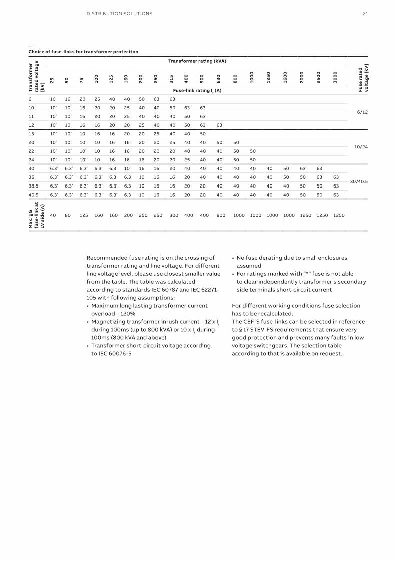
—Choice of fuse-links for transformer protection
Tran
sfo
rmer
ra
ted
volt
age
[kV
]
Transformer rating (kVA)
Fuse
rat
ed
volt
age
[kV
]
25 50 75 100
125
160
200
250
315
40
0
500
630
800
100
0
1250
160
0
200
0
250
0
300
0
Fuse-link rating Ir (A)
6 10 16 20 25 40 40 50 63 63
6/1210 10* 10 16 20 20 25 40 40 50 63 63
11 10* 10 16 20 20 25 40 40 40 50 63
12 10* 10 16 16 20 20 25 40 40 50 63 63
15 10* 10* 10 16 16 20 20 25 40 40 50
10/2420 10* 10* 10* 10 16 16 20 20 25 40 40 50 50
22 10* 10* 10* 10 16 16 20 20 20 40 40 40 50 50
24 10* 10* 10* 10 16 16 16 20 20 25 40 40 50 50
30 6.3* 6.3* 6.3* 6.3* 6.3 10 16 16 20 40 40 40 40 40 40 50 63 63
30/40.536 6.3* 6.3* 6.3* 6.3* 6.3 6.3 10 16 16 20 40 40 40 40 40 50 50 63 63
38.5 6.3* 6.3* 6.3* 6.3* 6.3* 6.3 10 16 16 20 20 40 40 40 40 40 50 50 63
40.5 6.3* 6.3* 6.3* 6.3* 6.3* 6.3 10 16 16 20 20 40 40 40 40 40 50 50 63
Max
. gG
fuse
-lin
k at
LV
sid
e (A
)
40 80 125 160 160 200 250 250 300 400 400 800 1000 1000 1000 1000 1250 1250 1250
Recommended fuse rating is on the crossing of transformer rating and line voltage. For different line voltage level, please use closest smaller value from the table. The table was calculated according to standards IEC 60787 and IEC 62271-105 with following assumptions:• Maximum long lasting transformer current
overload – 120%• Magnetizing transformer inrush current – 12 x Ir
during 100ms (up to 800 kVA) or 10 x Ir during 100ms (800 kVA and above)
• Transformer short-circuit voltage according to IEC 60076-5
• No fuse derating due to small enclosures assumed
• For ratings marked with “*” fuse is not able to clear independently transformer’s secondary side terminals short-circuit current
For different working conditions fuse selection has to be recalculated.The CEF-S fuse-links can be selected in reference to § 17 STEV-FS requirements that ensure very good protection and prevents many faults in low voltage switchgears. The selection table according to that is available on request.
22 CEF-S – FUSE-LINKS FOR TRANSFORMER PROTECTION
0.01
0.1
1
10
100
1000
10 100 1000
Pre-
arci
ng t
ime
[s]
Prospective current [A]
10A10A10A 16A 20A 25A 40A 50A 63A
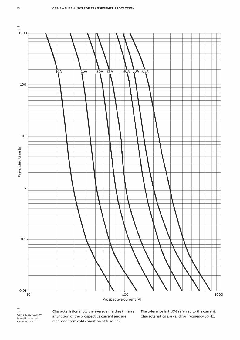
—13CEF-S 6/12, 10/24 kV fuses time-current characteristic
—13
Characteristics show the average melting time as a function of the prospective current and are recorded from cold condition of fuse-link.
The tolerance is ± 10% referred to the current.Characteristics are valid for frequency 50 Hz.
DISTRIBUTION SOLUTIONS 23
0.10.1
1
Max
imum
cut
-off
cur
rent
I pea
k [kA
]
10
100
1 10
Prospective short-circuit current Irms [kA]
100
1.8 x
√2 x
Ik
63A
50A
40A
25A
20A
16A
10A
—14CEF-S 6/12 kV, 10/24 kV cut-off current characteristics
—14
Characteristics show the cut-off current corresponding to a prospective short-circuit
current. Characteristics are valid for frequency 50Hz.
24 CEF-S – FUSE-LINKS FOR TRANSFORMER PROTECTION
—15CEF-S 30/40.5 kV time- -current characteristics
—15
Prospective current [A]
0.01
0.1
1
10
100
1000
10 100 1000 10000
Vir
tual
pre
-arc
ing
tim
e [s
]
63A50A
31.5A6.3A
10A16A
25A
40A20A
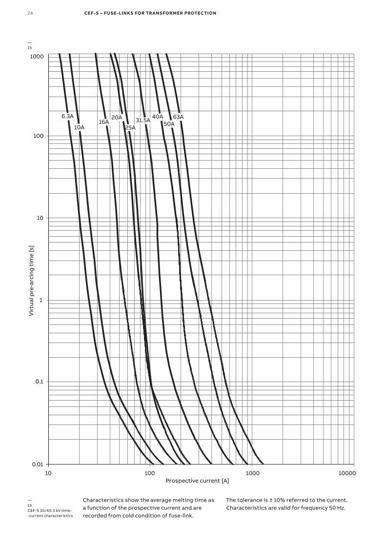
Characteristics show the average melting time as a function of the prospective current and are recorded from cold condition of fuse-link.
The tolerance is ± 10% referred to the current.Characteristics are valid for frequency 50 Hz.
DISTRIBUTION SOLUTIONS 25
1.8 x
√2 x
Ik
0.1
1
10
100
0.1 1 10 100
Prospective short-circuit current Irms [kA]
War
tość
szc
zyto
wa
prą
du
og
rani
czo
neg
o I p
eak [
kA]
63A
50A
40A
31.5A
25A
20A16A
6.3A
10A
—16CEF-S 30/40.5kV cut-off current characteristics
—16
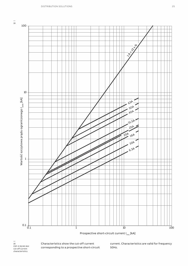
Characteristics show the cut-off current corresponding to a prospective short-circuit
current. Characteristics are valid for frequency 50Hz.
26 CEF-OT – OILTIGHT FUSE-LINKS FOR TRANSFORMER PROTECTION
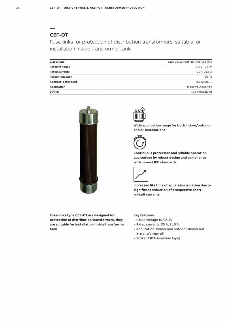
—CEF-OTFuse-links for protection of distribution transformers, suitable for installation inside transformer tank
Class, type Back-up, current limiting fuse-link
Rated voltages 12 kV – 24 kV
Rated currents 20 A, 31.5 A
Rated frequency 50 Hz
Applicable standard IEC 60282-1
Application Indoor/outdoor/oil
Striker 130 N (medium)
Wide application range for both indoor/outdoor and oil installations
Continuous protection and reliable operation guaranteed by robust design and compliance with newest IEC standards
Increased life time of apparatus isolation due to significant reduction of prospective short- -circuit currents
Fuse-links type CEF-OT are designed for protection of distribution transformers, they are suitable for installation inside transformer tank
Key features:• Rated voltage 10/24 kV• Rated currents: 20 A, 31.5 A• Application: indoor and outdoor, immersed
in transformer oil• Striker 130 N (medium type)
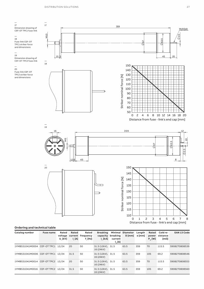
DISTRIBUTION SOLUTIONS 27
—17Dimension drawing of CEF-OT TPC1 fuse-link
—18Fuse-link CEF-OT TPC1 striker force and dimensions
—19Dimension drawing of CEF-OT TPC2 fuse-link
—20Fuse-link CEF-OT TPC2 striker force and dimensions
—17
—19
—18
—20
50
60
70
80
90
100
110
120
130
140
150
0 2 4 6 8 10 12 14 16 18 20
Stri
ker
nom
inal
fo
rce
[N]
Distance from fuse - link's end cap [mm]
4515
10M
5
359
20
2.5
Wybijak
63.5
67
Ordering and technical table
Catalog number Fuse name Rated voltage
Ur [kV]
Rated current
Ir [A]
Rated frequency
fr [Hz]
Breaking capacity
I1 [kA]
Minimal breaking
current I3 [A]
Diameter D [mm]
Length e [mm]
Rated power Pw [W]
Cold re-sistance
[mΩ]
EAN 13 Code
1YMB531041M0004 CEF-OT TPC1 12/24 20 50 31.5 (12kV), 16 (24kV)
31.5 63.5 359 70 115.5 5908270808539
1YMB531041M0006 CEF-OT TPC1 12/24 31.5 50 31.5 (12kV), 16 (24kV)
31.5 63.5 359 105 69.2 5908270808546
1YMB531041M0014 CEF-OT TPC2 12/24 20 50 31.5 (12kV), 16 (24kV)
31.5 63.5 359 70 115.5 5908270808553
1YMB531041M0016 CEF-OT TPC2 12/24 31.5 50 31.5 (12kV), 16 (24kV)
31.5 63.5 359 105 69.2 5908270808560
67
45
12
8
63.
5
6
2 .5
359
10
16
M6
12
110
115
120
125
130
135
140
145
150
0 1 2 3 4 5 6 7 8
Stri
ker
nom
inal
fo
rce
[N]
Distance from fuse - link's end cap [mm]
28 CEF-OT – OILTIGHT FUSE-LINKS FOR TRANSFORMER PROTECTION
0.01
0.1
1
10
100
1000
10000
1 10 100 1000Prospective current [A]
Pre-
arci
ng t
ime
[s]
31.5A20A
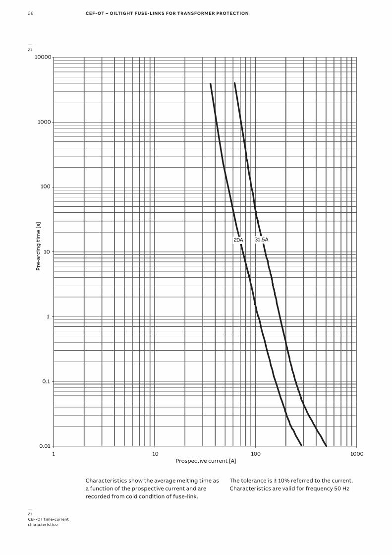
—21CEF-OT time-current characteristics:
—21
Characteristics show the average melting time as a function of the prospective current and are recorded from cold condition of fuse-link.
The tolerance is ± 10% referred to the current.Characteristics are valid for frequency 50 Hz
DISTRIBUTION SOLUTIONS 29
0.1
1
10
100
0.1 1 10 100Prospective short-circuit current Irms [kA]
Max
imum
cut
-off
cur
rent
I pea
k [kA
]
20A
31.5A
1.8 x
sqrt
(2) x
Ik
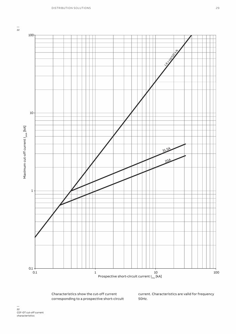
—22CEF-OT cut-off current characteristics
—22
Characteristics show the cut-off current corresponding to a prospective short-circuit
current. Characteristics are valid for frequency 50Hz.

30 MEDIUM-VOLTAGE FUSES 3 KV– 40.5 KV, 0.4 A – 315 A
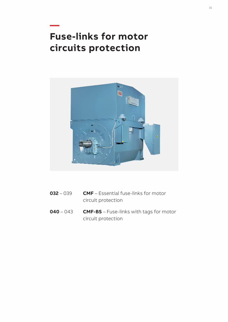
DISTRIBUTION SOLUTIONS 31
032 – 039 CMF – Essential fuse-links for motor circuit protection
040 – 043 CMF-BS – Fuse-links with tags for motor circuit protection
— Fuse-links for motor circuits protection
32 CMF – FUSE-LINKS FOR MOTOR PROTECTION
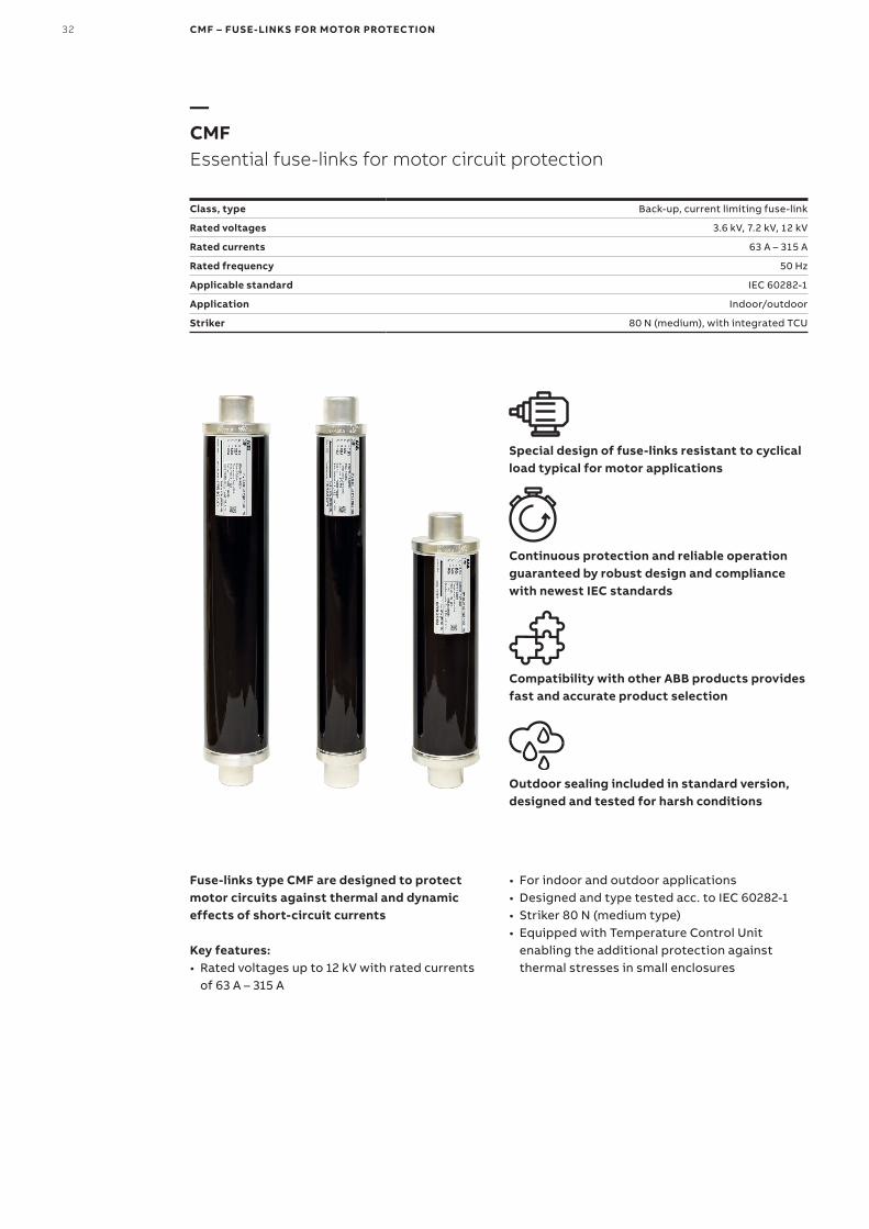
—CMFEssential fuse-links for motor circuit protection
Class, type Back-up, current limiting fuse-link
Rated voltages 3.6 kV, 7.2 kV, 12 kV
Rated currents 63 A – 315 A
Rated frequency 50 Hz
Applicable standard IEC 60282-1
Application Indoor/outdoor
Striker 80 N (medium), with integrated TCU
Special design of fuse-links resistant to cyclical load typical for motor applications
Continuous protection and reliable operation guaranteed by robust design and compliance with newest IEC standards
Compatibility with other ABB products provides fast and accurate product selection
Outdoor sealing included in standard version, designed and tested for harsh conditions
Fuse-links type CMF are designed to protect motor circuits against thermal and dynamic effects of short-circuit currents
Key features:• Rated voltages up to 12 kV with rated currents
of 63 A – 315 A
• For indoor and outdoor applications• Designed and type tested acc. to IEC 60282-1• Striker 80 N (medium type)• Equipped with Temperature Control Unit
enabling the additional protection against thermal stresses in small enclosures
DISTRIBUTION SOLUTIONS 33
34 34
e
D D
Ø45
Ø45
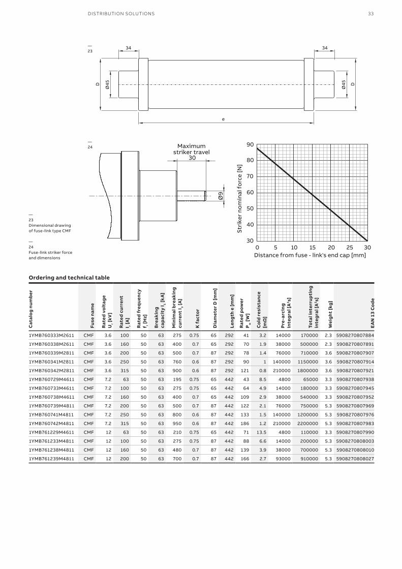
—23Dimensional drawing of fuse-link type CMF
—24Fuse-link striker force and dimensions
—23
Ø9
30
Maximumstriker travel
30
40
50
60
70
80
90
0 5 10 15 20 25 30
Stri
ker
nom
inal
fo
rce
[N]
Distance from fuse - link's end cap [mm]
—24
Ordering and technical table
Cat
alo
g nu
mb
er
Fuse
nam
e
Rat
ed v
olt
age
Ur [
kV]
Rat
ed c
urre
nt
I r [A
]
Rat
ed f
req
uenc
y f r [
Hz]
Bre
akin
g ca
pac
ity
I 1 [k
A]
Min
imal
bre
akin
g cu
rren
t I 3 [
A]
K f
acto
r
Dia
met
er D
[mm
]
Leng
th e
[mm
]
Rat
ed p
ower
P
w [
W]
Co
ld r
esis
tanc
e [m
Ω]
Pre-
arci
ng
inte
gra
l [A
2 s]
Tota
l int
erru
pti
ng
inte
gra
l [A
2 s]
Wei
ght
[kg
]
EA
N 1
3 C
od
e
1YMB760333M2611 CMF 3.6 100 50 63 275 0.75 65 292 41 3.2 14000 170000 2.3 5908270807884
1YMB760338M2611 CMF 3.6 160 50 63 400 0.7 65 292 70 1.9 38000 500000 2.3 5908270807891
1YMB760339M2811 CMF 3.6 200 50 63 500 0.7 87 292 78 1.4 76000 710000 3.6 5908270807907
1YMB760341M2811 CMF 3.6 250 50 63 760 0.6 87 292 90 1 140000 1150000 3.6 5908270807914
1YMB760342M2811 CMF 3.6 315 50 63 900 0.6 87 292 121 0.8 210000 1800000 3.6 5908270807921
1YMB760729M4611 CMF 7.2 63 50 63 195 0.75 65 442 43 8.5 4800 65000 3.3 5908270807938
1YMB760733M4611 CMF 7.2 100 50 63 275 0.75 65 442 64 4.9 14000 180000 3.3 5908270807945
1YMB760738M4611 CMF 7.2 160 50 63 400 0.7 65 442 109 2.9 38000 540000 3.3 5908270807952
1YMB760739M4811 CMF 7.2 200 50 63 500 0.7 87 442 122 2.1 76000 750000 5.3 5908270807969
1YMB760741M4811 CMF 7.2 250 50 63 800 0.6 87 442 133 1.5 140000 1200000 5.3 5908270807976
1YMB760742M4811 CMF 7.2 315 50 63 950 0.6 87 442 186 1.2 210000 2200000 5.3 5908270807983
1YMB761229M4611 CMF 12 63 50 63 210 0.75 65 442 71 13.5 4800 110000 3.3 5908270807990
1YMB761233M4811 CMF 12 100 50 63 275 0.75 87 442 88 6.6 14000 200000 5.3 5908270808003
1YMB761238M4811 CMF 12 160 50 63 480 0.7 87 442 139 3.9 38000 700000 5.3 5908270808010
1YMB761239M4811 CMF 12 200 50 63 700 0.7 87 442 166 2.7 93000 910000 5.3 5908270808027
34 CMF – FUSE-LINKS FOR MOTOR PROTECTION
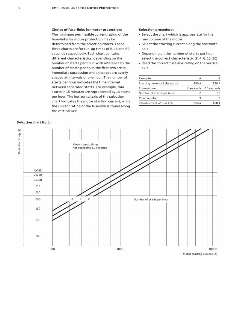
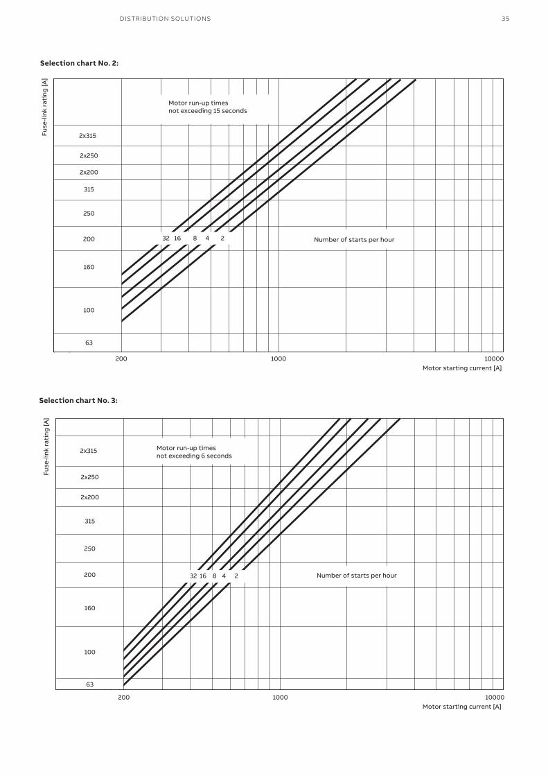
Choice of fuse-links for motor protection:The minimum permissible current rating of the fuse-links for motor protection may be determined from the selection charts. These three charts are for run-up times of 6, 15 and 60 seconds respectively. Each chart contains different characteristics, depending on the number of starts per hour. With reference to the number of starts per hour, the first two are in immediate succession while the rest are evenly spaced at intervals of one hour. The number of starts per hour indicates the time interval between separated starts. For example, four starts in 15 minutes are represented by 16 starts per hour. The horizontal axis of the selection chart indicates the motor starting current, while the current rating of the fuse-link is found along the vertical axis.
Selection procedure:• Select the chart which is appropriate for the
run-up time of the motor• Select the starting current along the horizontal
axis• Depending on the number of starts per hour,
select the correct characteristic (2, 4, 8, 16, 32)• Read the correct fuse-link rating on the vertical
axis.
Example A B
Starting current of the motor 850 A 250 A
Run-up time 6 seconds 15 seconds
Number of starts per hour 2 16
Chart number 3 2
Rated current of fuse link 250 A 160 A
Fuse
-link
rat
ing
[A]
Motor starting current [A]
Number of starts per hour
Motor run-up timesnot exceeding 60 seconds
2x315
2x250
2x200
315
250
200
160
100
63
200 1000 10000
8 4 2
Selection chart No. 1:
DISTRIBUTION SOLUTIONS 35
2x315
2x250
2x200
315
250
200 32 16 8 4 2
160
100
63
200 1000 10000
Fuse
-link
rat
ing
[A]
Motor starting current [A]
Number of starts per hour
Motor run-up timesnot exceeding 15 seconds
2x315
2x250
2x200
315
250
200 32 16 8 4 2
160
100
63
200 1000 10000
Fuse
-link
rat
ing
[A]
Motor starting current [A]
Number of starts per hour
Motor run-up timesnot exceeding 6 seconds
Selection chart No. 3:
Selection chart No. 2:
36 CMF – FUSE-LINKS FOR MOTOR PROTECTION
0.01
0.1
1
10
100
1000
100 1000 10000 100000
Pre-
arci
ngti
me
[s]
Prospective current [A]
100A
160A
200A
250A
315A
2x250A
2x315A
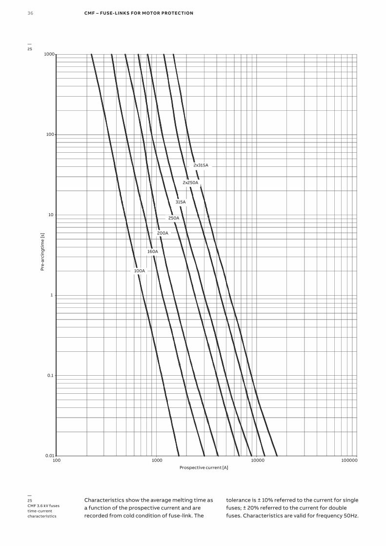
—25CMF 3.6 kV fuses time-current characteristics
—25
Characteristics show the average melting time as a function of the prospective current and are recorded from cold condition of fuse-link. The
tolerance is ± 10% referred to the current for single fuses; ± 20% referred to the current for double fuses. Characteristics are valid for frequency 50Hz.
DISTRIBUTION SOLUTIONS 37
0.01
0.1
1
10
100
1000
100 1000 10000 100000
Pre-
arci
ngti
me
[s]
Prospective current [A]
63A
100A
160A
200A
250A
315A
2x250A
2x315A
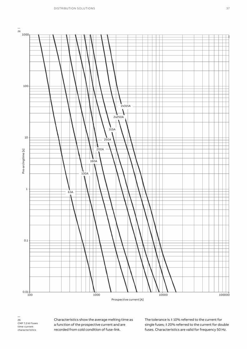
—26CMF 7.2 kV fuses time-current characteristics
—26
Characteristics show the average melting time as a function of the prospective current and are recorded from cold condition of fuse-link.
The tolerance is ± 10% referred to the current for single fuses; ± 20% referred to the current for double fuses. Characteristics are valid for frequency 50 Hz.
38 CMF – FUSE-LINKS FOR MOTOR PROTECTION
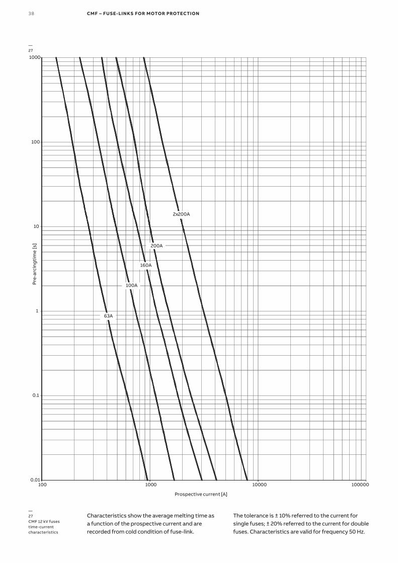
—27CMF 12 kV fuses time-current characteristics
—27
0.01
0.1
1
10
100
1000
100 1000 10000 100000
Pre
-arc
ing
tim
e [s
]
Prospective current [A]
63A
100A
160A
200A
2x200A
Characteristics show the average melting time as a function of the prospective current and are recorded from cold condition of fuse-link.
The tolerance is ± 10% referred to the current for single fuses; ± 20% referred to the current for double fuses. Characteristics are valid for frequency 50 Hz.
DISTRIBUTION SOLUTIONS 39
1
10
100
1 10 100
Max
imum
cut
-off
cur
rent
I pea
k [kA
]
Prospective short-circuit current I rms [kA]
63A1.8 x
sqrt
(2) x
Ik
100A
160A
200A
250A
315A
2x250A
2x315A
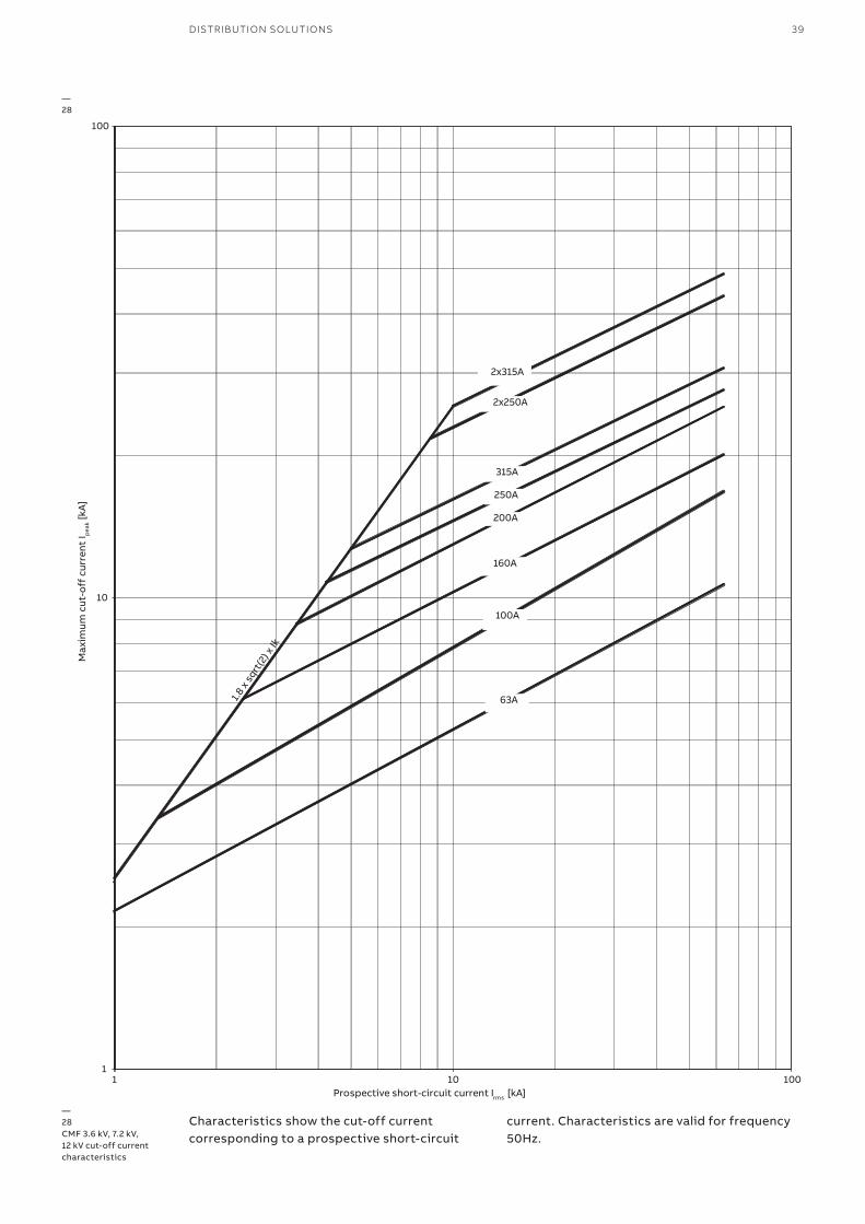
—28CMF 3.6 kV, 7.2 kV, 12 kV cut-off current characteristics
—28
Characteristics show the cut-off current corresponding to a prospective short-circuit
current. Characteristics are valid for frequency 50Hz.
40 CMF-BS – FUSE-LINKS FOR MOTOR PROTECTION
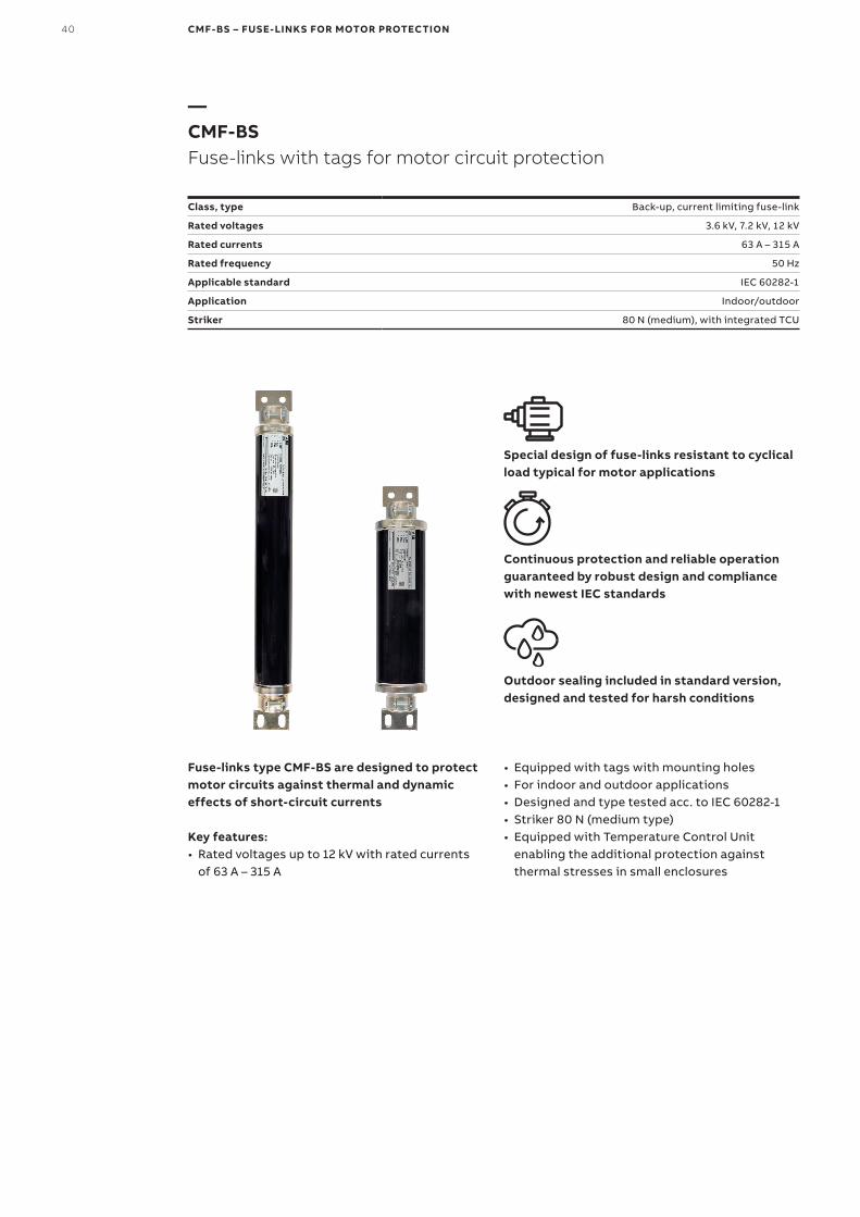
—CMF-BSFuse-links with tags for motor circuit protection
Class, type Back-up, current limiting fuse-link
Rated voltages 3.6 kV, 7.2 kV, 12 kV
Rated currents 63 A – 315 A
Rated frequency 50 Hz
Applicable standard IEC 60282-1
Application Indoor/outdoor
Striker 80 N (medium), with integrated TCU
Special design of fuse-links resistant to cyclical load typical for motor applications
Continuous protection and reliable operation guaranteed by robust design and compliance with newest IEC standards
Outdoor sealing included in standard version, designed and tested for harsh conditions
Fuse-links type CMF-BS are designed to protect motor circuits against thermal and dynamic effects of short-circuit currents
Key features:• Rated voltages up to 12 kV with rated currents
of 63 A – 315 A
• Equipped with tags with mounting holes• For indoor and outdoor applications• Designed and type tested acc. to IEC 60282-1• Striker 80 N (medium type)• Equipped with Temperature Control Unit
enabling the additional protection against thermal stresses in small enclosures
DISTRIBUTION SOLUTIONS 41
3
D
44
81 88
F
66.5
63
66.5
11
63
23
e
11
32
38
E
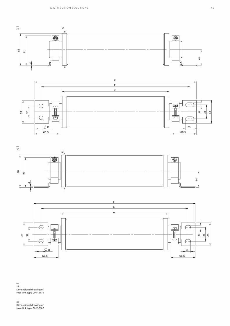
—29Dimensional drawing of fuse-link type CMF-BS-B
—30Dimensional drawing of fuse-link type CMF-BS-C
—29
—30
3 4
4
D
81 88
F
66.5
63
66.5
11
63
15
e
38
11
38
E
42 CMF-BS – FUSE-LINKS FOR MOTOR PROTECTION
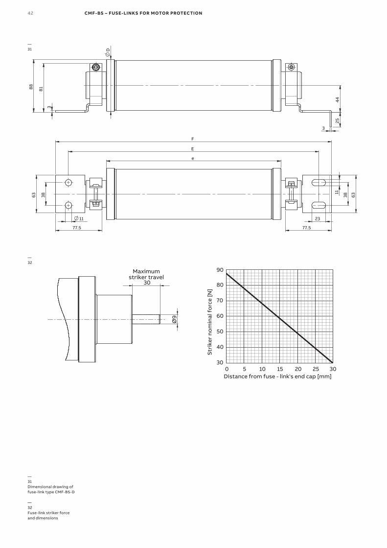
—31Dimensional drawing of fuse-link type CMF-BS-D
—32Fuse-link striker force and dimensions
3 4
4
D
81
25
88
3
F
77.5
63
77.5
11
63
23
e
38
11
38
E
—31
—32
Ø9
30
Maximumstriker travel
30
40
50
60
70
80
90
0 5 10 15 20 25 30
St
rike
r no
min
al f
orc
e [N
]
Distance from fuse - link's end cap [mm]
DISTRIBUTION SOLUTIONS 43
—Ordering and technical table
Cat
alo
g nu
mb
er
Fuse
nam
e
Rat
ed v
olt
age
Ur [
kV]
Rat
ed c
urre
nt
I r [A
]
Rat
ed f
req
uenc
y f r [
Hz]
Bre
akin
g ca
pac
ity
I 1 [k
A]
Min
imal
bre
akin
g cu
rren
t I 3 [
A]
Dia
met
er D
[mm
]
Leng
th e
[mm
]
Leng
th E
[mm
]
Leng
th F
[mm
]
Rat
ed p
ower
P
w [
W]
Co
ld r
esis
tanc
e [m
Ω]
Pre-
arci
ng
inte
gra
l [A
2 s]
Tota
l int
erru
pti
ng
inte
gra
l [A
2 s]
Wei
ght
[kg
]
EA
N 1
3 C
od
e
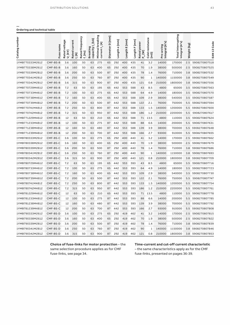
1YMB770333M2612 CMF-BS-B 3.6 100 50 63 275 65 292 400 435 41 3.2 14000 170000 2.5 5908270807518
1YMB770338M2612 CMF-BS-B 3.6 160 50 63 400 65 292 400 435 70 1.9 38000 500000 2.5 5908270807525
1YMB770339M2812 CMF-BS-B 3.6 200 50 63 500 87 292 400 435 78 1.4 76000 710000 3.8 5908270807532
1YMB770341M2812 CMF-BS-B 3.6 250 50 63 760 87 292 400 435 90 1 140000 1150000 3.8 5908270807549
1YMB770342M2812 CMF-BS-B 3.6 315 50 63 900 87 292 400 435 121 0.8 210000 1800000 3.8 5908270807556
1YMB770729M4612 CMF-BS-B 7.2 63 50 63 195 65 442 553 588 43 8.5 4800 65000 3.5 5908270807563
1YMB770733M4612 CMF-BS-B 7.2 100 50 63 275 65 442 553 588 64 4.9 14000 180000 3.5 5908270807570
1YMB770738M4612 CMF-BS-B 7.2 160 50 63 400 65 442 553 588 109 2.9 38000 540000 3.5 5908270807587
1YMB770739M4812 CMF-BS-B 7.2 200 50 63 500 87 442 553 588 122 2.1 76000 750000 5.5 5908270807594
1YMB770741M4812 CMF-BS-B 7.2 250 50 63 800 87 442 553 588 133 1.5 140000 1200000 5.5 5908270807600
1YMB770742M4812 CMF-BS-B 7.2 315 50 63 950 87 442 553 588 186 1.2 210000 2200000 5.5 5908270807617
1YMB771229M4612 CMF-BS-B 12 63 50 63 210 65 442 553 588 71 13.5 4800 110000 3.5 5908270807624
1YMB771233M4812 CMF-BS-B 12 100 50 63 275 87 442 553 588 88 6.6 14000 200000 5.5 5908270807631
1YMB771238M4812 CMF-BS-B 12 160 50 63 480 87 442 553 588 139 3.9 38000 700000 5.5 5908270807648
1YMB771239M4812 CMF-BS-B 12 200 50 63 700 87 442 553 588 166 2.7 93000 910000 5.5 5908270807655
1YMB780333M2612 CMF-BS-C 3.6 100 50 63 275 65 292 400 440 41 3.2 14000 170000 2.5 5908270807662
1YMB780338M2612 CMF-BS-C 3.6 160 50 63 400 65 292 400 440 70 1.9 38000 500000 2.5 5908270807679
1YMB780339M2812 CMF-BS-C 3.6 200 50 63 500 87 292 400 440 78 1.4 76000 710000 3.8 5908270807686
1YMB780341M2812 CMF-BS-C 3.6 250 50 63 760 87 292 400 440 90 1 140000 1150000 3.8 5908270807693
1YMB780342M2812 CMF-BS-C 3.6 315 50 63 900 87 292 400 440 121 0.8 210000 1800000 3.8 5908270807709
1YMB780729M4612 CMF-BS-C 7.2 63 50 63 195 65 442 553 593 43 8.5 4800 65000 3.5 5908270807716
1YMB780733M4612 CMF-BS-C 7.2 100 50 63 275 65 442 553 593 64 4.9 14000 180000 3.5 5908270807723
1YMB780738M4612 CMF-BS-C 7.2 160 50 63 400 65 442 553 593 109 2.9 38000 540000 3.5 5908270807730
1YMB780739M4812 CMF-BS-C 7.2 200 50 63 500 87 442 553 593 122 2.1 76000 750000 5.5 5908270807747
1YMB780741M4812 CMF-BS-C 7.2 250 50 63 800 87 442 553 593 133 1.5 140000 1200000 5.5 5908270807754
1YMB780742M4812 CMF-BS-C 7.2 315 50 63 950 87 442 553 593 186 1.2 210000 2200000 5.5 5908270807761
1YMB781229M4612 CMF-BS-C 12 63 50 63 210 65 442 553 593 71 13.5 4800 110000 3.5 5908270807778
1YMB781233M4812 CMF-BS-C 12 100 50 63 275 87 442 553 593 88 6.6 14000 200000 5.5 5908270807785
1YMB781238M4812 CMF-BS-C 12 160 50 63 480 87 442 553 593 139 3.9 38000 700000 5.5 5908270807792
1YMB781239M4812 CMF-BS-C 12 200 50 63 700 87 442 553 593 166 2.7 93000 910000 5.5 5908270807808
1YMB790333M2612 CMF-BS-D 3.6 100 50 63 275 65 292 419 462 41 3.2 14000 170000 2.5 5908270807815
1YMB790338M2612 CMF-BS-D 3.6 160 50 63 400 65 292 419 462 70 1.9 38000 500000 2.5 5908270807822
1YMB790339M2812 CMF-BS-D 3.6 200 50 63 500 87 292 419 462 78 1.4 76000 710000 3.8 5908270807839
1YMB790341M2812 CMF-BS-D 3.6 250 50 63 760 87 292 419 462 90 1 140000 1150000 3.8 5908270807846
1YMB790342M2812 CMF-BS-D 3.6 315 50 63 900 87 292 419 462 121 0.8 210000 1800000 3.8 5908270807853
Choice of fuse-links for motor protection – the same selection procedure applies as for CMF fuse-links, see page 34.
Time-current and cut-off current characteristic – the same characteristics apply as for the CMF fuse-links, presented on pages 36-39.

44 MEDIUM-VOLTAGE FUSES 3 KV– 40.5 KV, 0.4 A – 315 A
DISTRIBUTION SOLUTIONS 45
046 – 051 CEF-VT – Essential fuse-links for voltage transformer protection
052 – 058 WBP – Compact fuse-links for voltage transformer protection
— Fuse-links for voltage transformer protection
46 CEF-VT – FUSE-LINKS FOR VOLTAGE TRANSFORMER PROTECTION
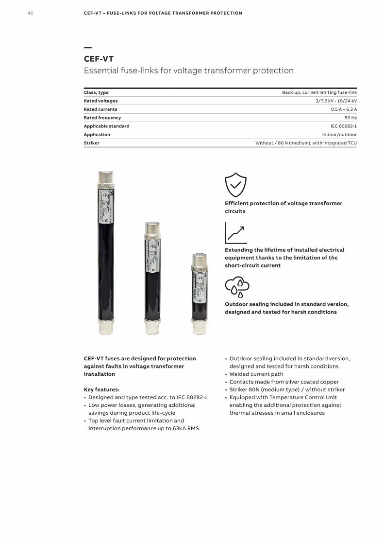
—CEF-VTEssential fuse-links for voltage transformer protection
Class, type Back-up, current limiting fuse-link
Rated voltages 3/7.2 kV - 10/24 kV
Rated currents 0.5 A – 6.3 A
Rated frequency 50 Hz
Applicable standard IEC 60282-1
Application Indoor/outdoor
Striker Without / 80 N (medium), with integrated TCU
Efficient protection of voltage transformer circuits
Extending the lifetime of installed electrical equipment thanks to the limitation of the short-circuit current
Outdoor sealing included in standard version, designed and tested for harsh conditions
CEF-VT fuses are designed for protection against faults in voltage transformer installation
Key features:• Designed and type tested acc. to IEC 60282-1• Low power losses, generating additional
savings during product life-cycle• Top level fault current limitation and
interruption performance up to 63kA RMS
• Outdoor sealing included in standard version, designed and tested for harsh conditions
• Welded current path• Contacts made from silver coated copper• Striker 80N (medium type) / without striker• Equipped with Temperature Control Unit
enabling the additional protection against thermal stresses in small enclosures
DISTRIBUTION SOLUTIONS 47
34 34
e
D D
Ø45
Ø45
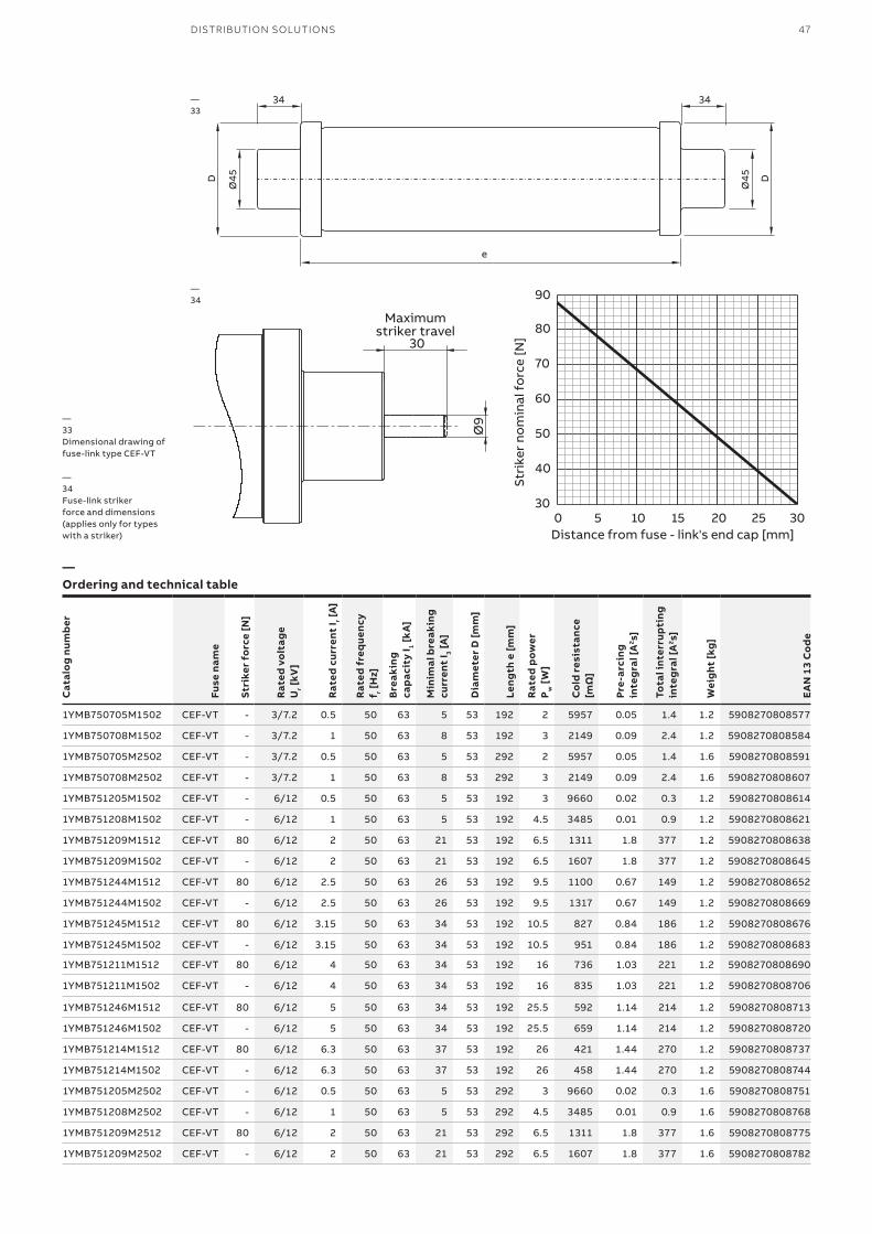
—33Dimensional drawing of fuse-link type CEF-VT
—34Fuse-link striker force and dimensions (applies only for types with a striker)
—33
Ø9
30
Maximumstriker travel
30
40
50
60
70
80
90
0 5 10 15 20 25 30
Stri
ker
nom
inal
fo
rce
[N]
Distance from fuse - link's end cap [mm]
—34
—Ordering and technical table
Cat
alo
g nu
mb
er
Fuse
nam
e
Stri
ker
forc
e [N
]
Rat
ed v
olt
age
Ur [
kV]
Rat
ed c
urre
nt I r [
A]
Rat
ed f
req
uenc
y f r [
Hz]
Bre
akin
g ca
pac
ity
I 1 [k
A]
Min
imal
bre
akin
g cu
rren
t I 3 [
A]
Dia
met
er D
[mm
]
Leng
th e
[mm
]
Rat
ed p
ower
P
w [
W]
Co
ld r
esis
tanc
e [m
Ω]
Pre-
arci
ng
inte
gra
l [A
2 s]
Tota
l int
erru
pti
ng
inte
gra
l [A
2 s]
Wei
ght
[kg
]
EA
N 1
3 C
od
e
1YMB750705M1502 CEF-VT - 3/7.2 0.5 50 63 5 53 192 2 5957 0.05 1.4 1.2 5908270808577
1YMB750708M1502 CEF-VT - 3/7.2 1 50 63 8 53 192 3 2149 0.09 2.4 1.2 5908270808584
1YMB750705M2502 CEF-VT - 3/7.2 0.5 50 63 5 53 292 2 5957 0.05 1.4 1.6 5908270808591
1YMB750708M2502 CEF-VT - 3/7.2 1 50 63 8 53 292 3 2149 0.09 2.4 1.6 5908270808607
1YMB751205M1502 CEF-VT - 6/12 0.5 50 63 5 53 192 3 9660 0.02 0.3 1.2 5908270808614
1YMB751208M1502 CEF-VT - 6/12 1 50 63 5 53 192 4.5 3485 0.01 0.9 1.2 5908270808621
1YMB751209M1512 CEF-VT 80 6/12 2 50 63 21 53 192 6.5 1311 1.8 377 1.2 5908270808638
1YMB751209M1502 CEF-VT - 6/12 2 50 63 21 53 192 6.5 1607 1.8 377 1.2 5908270808645
1YMB751244M1512 CEF-VT 80 6/12 2.5 50 63 26 53 192 9.5 1100 0.67 149 1.2 5908270808652
1YMB751244M1502 CEF-VT - 6/12 2.5 50 63 26 53 192 9.5 1317 0.67 149 1.2 5908270808669
1YMB751245M1512 CEF-VT 80 6/12 3.15 50 63 34 53 192 10.5 827 0.84 186 1.2 5908270808676
1YMB751245M1502 CEF-VT - 6/12 3.15 50 63 34 53 192 10.5 951 0.84 186 1.2 5908270808683
1YMB751211M1512 CEF-VT 80 6/12 4 50 63 34 53 192 16 736 1.03 221 1.2 5908270808690
1YMB751211M1502 CEF-VT - 6/12 4 50 63 34 53 192 16 835 1.03 221 1.2 5908270808706
1YMB751246M1512 CEF-VT 80 6/12 5 50 63 34 53 192 25.5 592 1.14 214 1.2 5908270808713
1YMB751246M1502 CEF-VT - 6/12 5 50 63 34 53 192 25.5 659 1.14 214 1.2 5908270808720
1YMB751214M1512 CEF-VT 80 6/12 6.3 50 63 37 53 192 26 421 1.44 270 1.2 5908270808737
1YMB751214M1502 CEF-VT - 6/12 6.3 50 63 37 53 192 26 458 1.44 270 1.2 5908270808744
1YMB751205M2502 CEF-VT - 6/12 0.5 50 63 5 53 292 3 9660 0.02 0.3 1.6 5908270808751
1YMB751208M2502 CEF-VT - 6/12 1 50 63 5 53 292 4.5 3485 0.01 0.9 1.6 5908270808768
1YMB751209M2512 CEF-VT 80 6/12 2 50 63 21 53 292 6.5 1311 1.8 377 1.6 5908270808775
1YMB751209M2502 CEF-VT - 6/12 2 50 63 21 53 292 6.5 1607 1.8 377 1.6 5908270808782
48 CEF-VT – FUSE-LINKS FOR VOLTAGE TRANSFORMER PROTECTION
Cat
alo
g nu
mb
er
Fuse
nam
e
Stri
ker
forc
e [N
]
Rat
ed v
olt
age
Ur [
kV]
Rat
ed c
urre
nt I r [
A]
Rat
ed f
req
uenc
y f r [
Hz]
Bre
akin
g ca
pac
ity
I 1 [k
A]
Min
imal
bre
akin
g cu
rren
t I 3 [
A]
Dia
met
er D
[mm
]
Leng
th e
[mm
]
Rat
ed p
ower
P
w [
W]
Co
ld r
esis
tanc
e [m
Ω]
Pre-
arci
ng
inte
gra
l [A
2 s]
Tota
l int
erru
pti
ng
inte
gra
l [A
2 s]
Wei
ght
[kg
]
EA
N 1
3 C
od
e
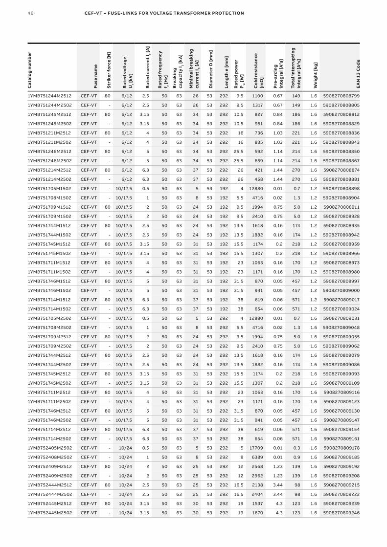
1YMB751244M2512 CEF-VT 80 6/12 2.5 50 63 26 53 292 9.5 1100 0.67 149 1.6 5908270808799
1YMB751244M2502 CEF-VT - 6/12 2.5 50 63 26 53 292 9.5 1317 0.67 149 1.6 5908270808805
1YMB751245M2512 CEF-VT 80 6/12 3.15 50 63 34 53 292 10.5 827 0.84 186 1.6 5908270808812
1YMB751245M2502 CEF-VT - 6/12 3.15 50 63 34 53 292 10.5 951 0.84 186 1.6 5908270808829
1YMB751211M2512 CEF-VT 80 6/12 4 50 63 34 53 292 16 736 1.03 221 1.6 5908270808836
1YMB751211M2502 CEF-VT - 6/12 4 50 63 34 53 292 16 835 1.03 221 1.6 5908270808843
1YMB751246M2512 CEF-VT 80 6/12 5 50 63 34 53 292 25.5 592 1.14 214 1.6 5908270808850
1YMB751246M2502 CEF-VT - 6/12 5 50 63 34 53 292 25.5 659 1.14 214 1.6 5908270808867
1YMB751214M2512 CEF-VT 80 6/12 6.3 50 63 37 53 292 26 421 1.44 270 1.6 5908270808874
1YMB751214M2502 CEF-VT - 6/12 6.3 50 63 37 53 292 26 458 1.44 270 1.6 5908270808881
1YMB751705M1502 CEF-VT - 10/17.5 0.5 50 63 5 53 192 4 12880 0.01 0.7 1.2 5908270808898
1YMB751708M1502 CEF-VT - 10/17.5 1 50 63 8 53 192 5.5 4716 0.02 1.3 1.2 5908270808904
1YMB751709M1512 CEF-VT 80 10/17.5 2 50 63 24 53 192 9.5 1994 0.75 5.0 1.2 5908270808911
1YMB751709M1502 CEF-VT - 10/17.5 2 50 63 24 53 192 9.5 2410 0.75 5.0 1.2 5908270808928
1YMB751744M1512 CEF-VT 80 10/17.5 2.5 50 63 24 53 192 13.5 1618 0.16 174 1.2 5908270808935
1YMB751744M1502 CEF-VT - 10/17.5 2.5 50 63 24 53 192 13.5 1882 0.16 174 1.2 5908270808942
1YMB751745M1512 CEF-VT 80 10/17.5 3.15 50 63 31 53 192 15.5 1174 0.2 218 1.2 5908270808959
1YMB751745M1502 CEF-VT - 10/17.5 3.15 50 63 31 53 192 15.5 1307 0.2 218 1.2 5908270808966
1YMB751711M1512 CEF-VT 80 10/17.5 4 50 63 31 53 192 23 1063 0.16 170 1.2 5908270808973
1YMB751711M1502 CEF-VT - 10/17.5 4 50 63 31 53 192 23 1171 0.16 170 1.2 5908270808980
1YMB751746M1512 CEF-VT 80 10/17.5 5 50 63 31 53 192 31.5 870 0.05 457 1.2 5908270808997
1YMB751746M1502 CEF-VT - 10/17.5 5 50 63 31 53 192 31.5 941 0.05 457 1.2 5908270809000
1YMB751714M1512 CEF-VT 80 10/17.5 6.3 50 63 37 53 192 38 619 0.06 571 1.2 5908270809017
1YMB751714M1502 CEF-VT - 10/17.5 6.3 50 63 37 53 192 38 654 0.06 571 1.2 5908270809024
1YMB751705M2502 CEF-VT - 10/17.5 0.5 50 63 5 53 292 4 12880 0.01 0.7 1.6 5908270809031
1YMB751708M2502 CEF-VT - 10/17.5 1 50 63 8 53 292 5.5 4716 0.02 1.3 1.6 5908270809048
1YMB751709M2512 CEF-VT 80 10/17.5 2 50 63 24 53 292 9.5 1994 0.75 5.0 1.6 5908270809055
1YMB751709M2502 CEF-VT - 10/17.5 2 50 63 24 53 292 9.5 2410 0.75 5.0 1.6 5908270809062
1YMB751744M2512 CEF-VT 80 10/17.5 2.5 50 63 24 53 292 13.5 1618 0.16 174 1.6 5908270809079
1YMB751744M2502 CEF-VT - 10/17.5 2.5 50 63 24 53 292 13.5 1882 0.16 174 1.6 5908270809086
1YMB751745M2512 CEF-VT 80 10/17.5 3.15 50 63 31 53 292 15.5 1174 0.2 218 1.6 5908270809093
1YMB751745M2502 CEF-VT - 10/17.5 3.15 50 63 31 53 292 15.5 1307 0.2 218 1.6 5908270809109
1YMB751711M2512 CEF-VT 80 10/17.5 4 50 63 31 53 292 23 1063 0.16 170 1.6 5908270809116
1YMB751711M2502 CEF-VT - 10/17.5 4 50 63 31 53 292 23 1171 0.16 170 1.6 5908270809123
1YMB751746M2512 CEF-VT 80 10/17.5 5 50 63 31 53 292 31.5 870 0.05 457 1.6 5908270809130
1YMB751746M2502 CEF-VT - 10/17.5 5 50 63 31 53 292 31.5 941 0.05 457 1.6 5908270809147
1YMB751714M2512 CEF-VT 80 10/17.5 6.3 50 63 37 53 292 38 619 0.06 571 1.6 5908270809154
1YMB751714M2502 CEF-VT - 10/17.5 6.3 50 63 37 53 292 38 654 0.06 571 1.6 5908270809161
1YMB752405M2502 CEF-VT - 10/24 0.5 50 63 5 53 292 5 17709 0.01 0.3 1.6 5908270809178
1YMB752408M2502 CEF-VT - 10/24 1 50 63 8 53 292 8 6389 0.01 0.9 1.6 5908270809185
1YMB752409M2512 CEF-VT 80 10/24 2 50 63 25 53 292 12 2568 1.23 139 1.6 5908270809192
1YMB752409M2502 CEF-VT - 10/24 2 50 63 25 53 292 12 2962 1.23 139 1.6 5908270809208
1YMB752444M2512 CEF-VT 80 10/24 2.5 50 63 25 53 292 16.5 2138 3.44 98 1.6 5908270809215
1YMB752444M2502 CEF-VT - 10/24 2.5 50 63 25 53 292 16.5 2404 3.44 98 1.6 5908270809222
1YMB752445M2512 CEF-VT 80 10/24 3.15 50 63 30 53 292 19 1537 4.3 123 1.6 5908270809239
1YMB752445M2502 CEF-VT - 10/24 3.15 50 63 30 53 292 19 1670 4.3 123 1.6 5908270809246
DISTRIBUTION SOLUTIONS 49
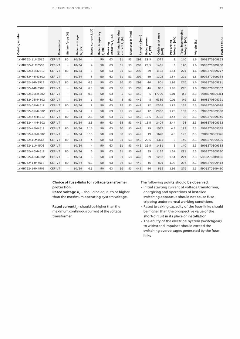
Choice of fuse-links for voltage transformer protection:Rated voltage Ur – should be equal to or higher than the maximum operating system voltage.
Rated current Ir – should be higher than the maximum continuous current of the voltage transformer.
The following points should be observed:• Initial starting current of voltage transformer,
energizing and operations of installed switching apparatus should not cause fuse tripping under normal working conditions
• Rated breaking capacity of the fuse-links should be higher than the prospective value of the short-circuit in its place of installation
• The ability of the electrical system (switchgear) to withstand impulses should exceed the switching overvoltages generated by the fuse-links
Cat
alo
g nu
mb
er
Fuse
nam
e
Stri
ker
forc
e [N
]
Rat
ed v
olt
age
Ur [
kV]
Rat
ed c
urre
nt I r [
A]
Rat
ed f
req
uenc
y f r [
Hz]
Bre
akin
g ca
pac
ity
I 1 [k
A]
Min
imal
bre
akin
g cu
rren
t I 3 [
A]
Dia
met
er D
[mm
]
Leng
th e
[mm
]
Rat
ed p
ower
P
w [
W]
Co
ld r
esis
tanc
e [m
Ω]
Pre-
arci
ng
inte
gra
l [A
2 s]
Tota
l int
erru
pti
ng
inte
gra
l [A
2 s]
Wei
ght
[kg
]
EA
N 1
3 C
od
e
1YMB752411M2512 CEF-VT 80 10/24 4 50 63 31 53 292 29.5 1375 2 140 1.6 5908270809253
1YMB752411M2502 CEF-VT - 10/24 4 50 63 31 53 292 29.5 1481 2 140 1.6 5908270809260
1YMB752446M2512 CEF-VT 80 10/24 5 50 63 31 53 292 39 1132 1.54 221 1.6 5908270809277
1YMB752446M2502 CEF-VT - 10/24 5 50 63 31 53 292 39 1202 1.54 221 1.6 5908270809284
1YMB752414M2512 CEF-VT 80 10/24 6.3 50 63 36 53 292 46 801 1.92 276 1.6 5908270809291
1YMB752414M2502 CEF-VT - 10/24 6.3 50 63 36 53 292 46 835 1.92 276 1.6 5908270809307
1YMB752405M4502 CEF-VT - 10/24 0.5 50 63 5 53 442 5 17709 0.01 0.3 2.3 5908270809314
1YMB752408M4502 CEF-VT - 10/24 1 50 63 8 53 442 8 6389 0.01 0.9 2.3 5908270809321
1YMB752409M4512 CEF-VT 80 10/24 2 50 63 25 53 442 12 2568 1.23 139 2.3 5908270806528
1YMB752409M4502 CEF-VT - 10/24 2 50 63 25 53 442 12 2962 1.23 139 2.3 5908270809338
1YMB752444M4512 CEF-VT 80 10/24 2.5 50 63 25 53 442 16.5 2138 3.44 98 2.3 5908270809345
1YMB752444M4502 CEF-VT - 10/24 2.5 50 63 25 53 442 16.5 2404 3.44 98 2.3 5908270809352
1YMB752445M4512 CEF-VT 80 10/24 3.15 50 63 30 53 442 19 1537 4.3 123 2.3 5908270809369
1YMB752445M4502 CEF-VT - 10/24 3.15 50 63 30 53 442 19 1670 4.3 123 2.3 5908270809376
1YMB752411M4512 CEF-VT 80 10/24 4 50 63 31 53 442 29.5 1375 2 140 2.3 5908270806535
1YMB752411M4502 CEF-VT - 10/24 4 50 63 31 53 442 29.5 1481 2 140 2.3 5908270809383
1YMB752446M4512 CEF-VT 80 10/24 5 50 63 31 53 442 39 1132 1.54 221 2.3 5908270809390
1YMB752446M4502 CEF-VT - 10/24 5 50 63 31 53 442 39 1202 1.54 221 2.3 5908270809406
1YMB752414M4512 CEF-VT 80 10/24 6.3 50 63 36 53 442 46 801 1.92 276 2.3 5908270809413
1YMB752414M4502 CEF-VT - 10/24 6.3 50 63 36 53 442 46 835 1.92 276 2.3 5908270809420
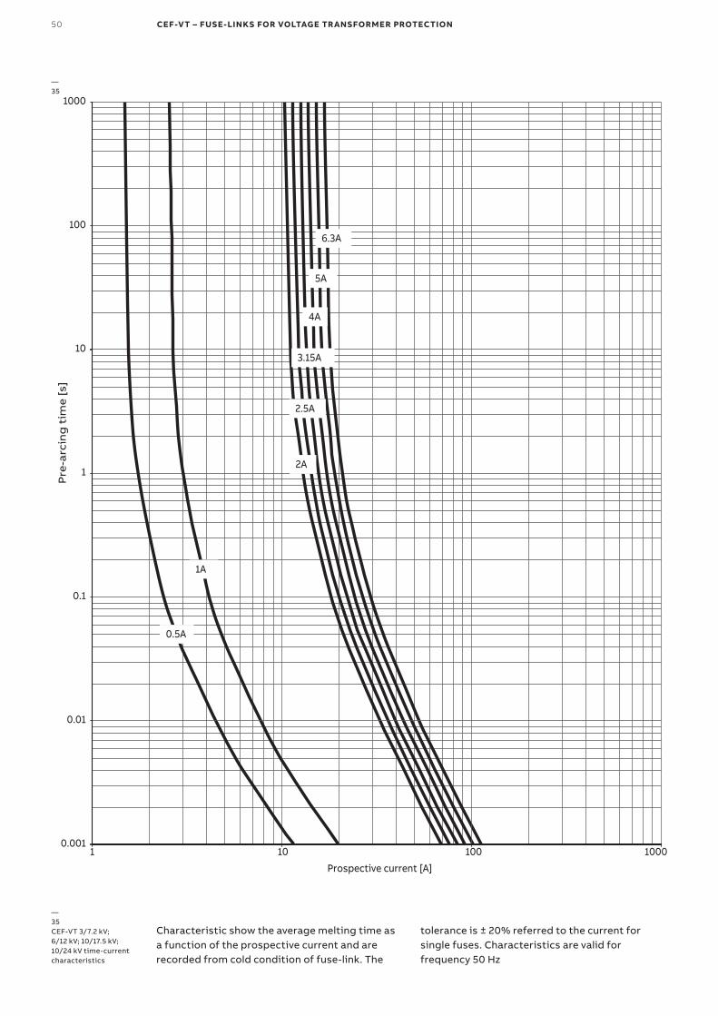
50 CEF-VT – FUSE-LINKS FOR VOLTAGE TRANSFORMER PROTECTION
0.001
0.01
0.1
1
10
100
1000
1 10 100 1000
Pre
-arc
ing
tim
e [s
]
Prospective current [A]
2A
0.5A
1A
2.5A
3.15A
4A
5A
6.3A
Characteristic show the average melting time as a function of the prospective current and are recorded from cold condition of fuse-link. The
tolerance is ± 20% referred to the current for single fuses. Characteristics are valid for frequency 50 Hz
—35CEF-VT 3/7.2 kV; 6/12 kV; 10/17.5 kV; 10/24 kV time-current characteristics
—35
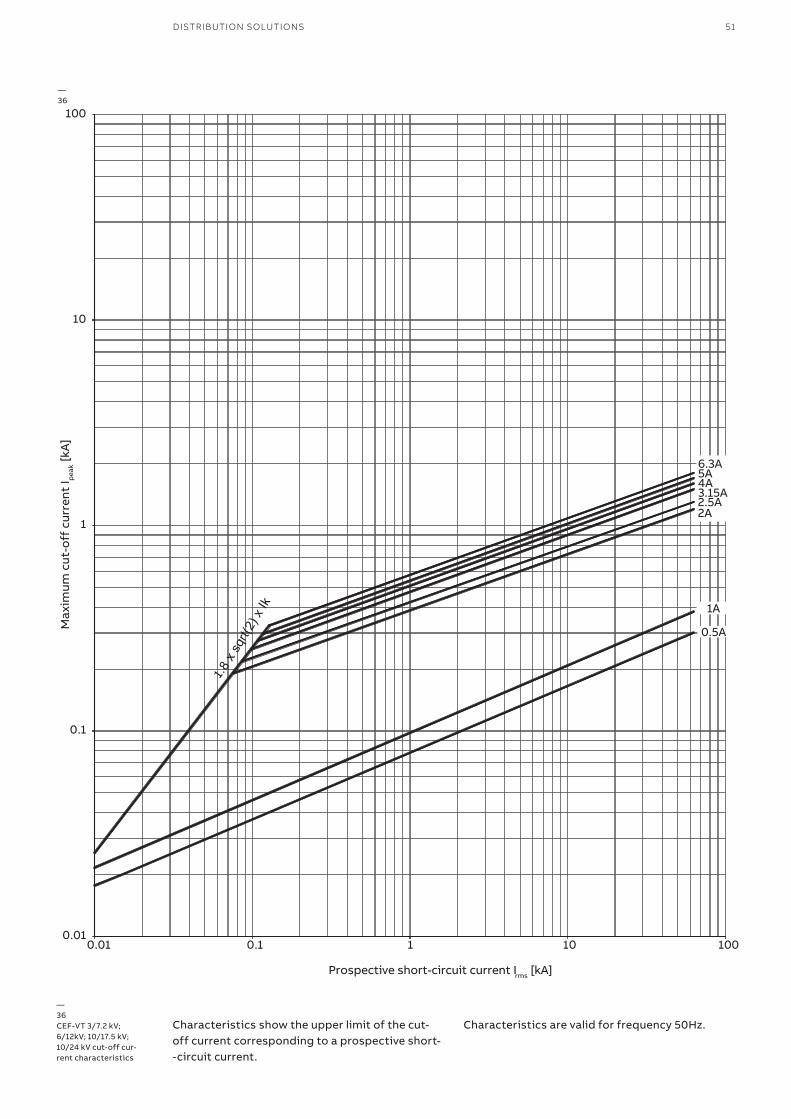
DISTRIBUTION SOLUTIONS 51
0.01
0.
.
1
1
1
10
100
0.01 0.1 1 10 100
Max
imum
cut
-off
cur
rent
I pea
k [kA
]
0.5A
1A
Prospective short-circuit current Irms [kA]
2A2.5A3.15A4A5A6.3A
Characteristics show the upper limit of the cut-off current corresponding to a prospective short- -circuit current.
Characteristics are valid for frequency 50Hz.
—36CEF-VT 3/7.2 kV; 6/12kV; 10/17.5 kV; 10/24 kV cut-off cur-rent characteristics
—36
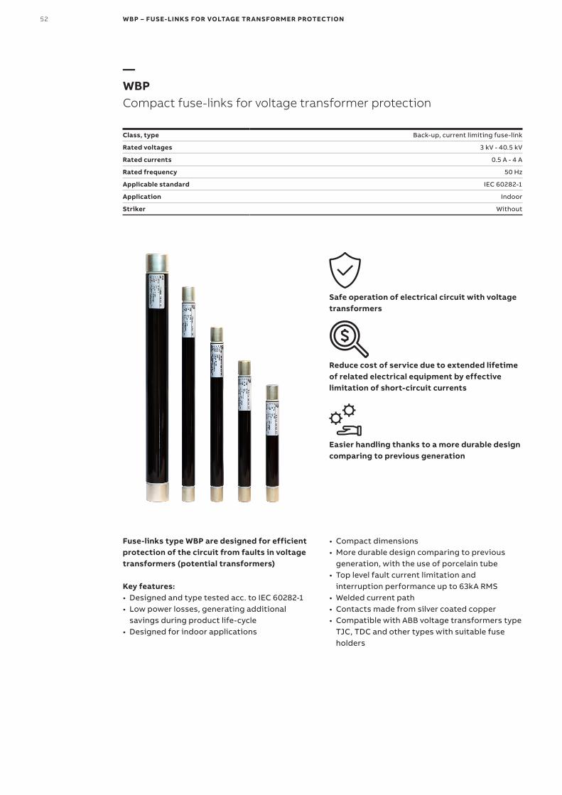
52 WBP – FUSE-LINKS FOR VOLTAGE TRANSFORMER PROTECTION
—WBPCompact fuse-links for voltage transformer protection
Class, type Back-up, current limiting fuse-link
Rated voltages 3 kV - 40.5 kV
Rated currents 0.5 A - 4 A
Rated frequency 50 Hz
Applicable standard IEC 60282-1
Application Indoor
Striker Without
Safe operation of electrical circuit with voltage transformers
Reduce cost of service due to extended lifetime of related electrical equipment by effective limitation of short-circuit currents
Easier handling thanks to a more durable design comparing to previous generation
Fuse-links type WBP are designed for efficient protection of the circuit from faults in voltage transformers (potential transformers)
Key features:• Designed and type tested acc. to IEC 60282-1• Low power losses, generating additional
savings during product life-cycle• Designed for indoor applications
• Compact dimensions• More durable design comparing to previous
generation, with the use of porcelain tube• Top level fault current limitation and
interruption performance up to 63kA RMS• Welded current path• Contacts made from silver coated copper• Compatible with ABB voltage transformers type
TJC, TDC and other types with suitable fuse holders
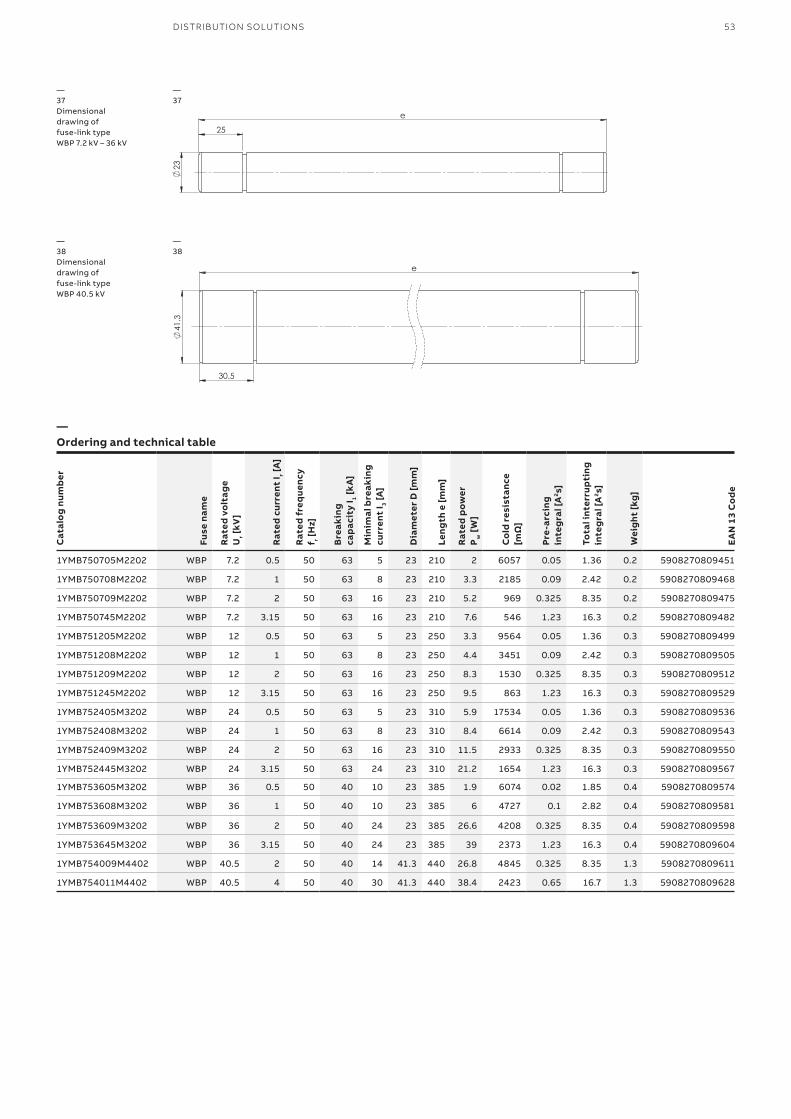
53DISTRIBUTION SOLUTIONS
—37Dimensionaldrawing offuse-link typeWBP 7.2 kV – 36 kV
—38Dimensionaldrawing offuse-link typeWBP 40.5 kV
—37
—38
—Ordering and technical table
Cat
alo
g nu
mb
er
Fuse
nam
e
Rat
ed v
olt
age
Ur [
kV]
Rat
ed c
urre
nt I r [
A]
Rat
ed f
req
uenc
y f r [
Hz]
Bre
akin
g ca
pac
ity
I 1 [k
A]
Min
imal
bre
akin
g cu
rren
t I 3 [
A]
Dia
met
er D
[mm
]
Leng
th e
[mm
]
Rat
ed p
ower
P
w [
W]
Co
ld r
esis
tanc
e [m
Ω]
Pre-
arci
ng
inte
gra
l [A
2 s]
Tota
l int
erru
pti
ng
inte
gra
l [A
2 s]
Wei
ght
[kg
]
EA
N 1
3 C
od
e
1YMB750705M2202 WBP 7.2 0.5 50 63 5 23 210 2 6057 0.05 1.36 0.2 5908270809451
1YMB750708M2202 WBP 7.2 1 50 63 8 23 210 3.3 2185 0.09 2.42 0.2 5908270809468
1YMB750709M2202 WBP 7.2 2 50 63 16 23 210 5.2 969 0.325 8.35 0.2 5908270809475
1YMB750745M2202 WBP 7.2 3.15 50 63 16 23 210 7.6 546 1.23 16.3 0.2 5908270809482
1YMB751205M2202 WBP 12 0.5 50 63 5 23 250 3.3 9564 0.05 1.36 0.3 5908270809499
1YMB751208M2202 WBP 12 1 50 63 8 23 250 4.4 3451 0.09 2.42 0.3 5908270809505
1YMB751209M2202 WBP 12 2 50 63 16 23 250 8.3 1530 0.325 8.35 0.3 5908270809512
1YMB751245M2202 WBP 12 3.15 50 63 16 23 250 9.5 863 1.23 16.3 0.3 5908270809529
1YMB752405M3202 WBP 24 0.5 50 63 5 23 310 5.9 17534 0.05 1.36 0.3 5908270809536
1YMB752408M3202 WBP 24 1 50 63 8 23 310 8.4 6614 0.09 2.42 0.3 5908270809543
1YMB752409M3202 WBP 24 2 50 63 16 23 310 11.5 2933 0.325 8.35 0.3 5908270809550
1YMB752445M3202 WBP 24 3.15 50 63 24 23 310 21.2 1654 1.23 16.3 0.3 5908270809567
1YMB753605M3202 WBP 36 0.5 50 40 10 23 385 1.9 6074 0.02 1.85 0.4 5908270809574
1YMB753608M3202 WBP 36 1 50 40 10 23 385 6 4727 0.1 2.82 0.4 5908270809581
1YMB753609M3202 WBP 36 2 50 40 24 23 385 26.6 4208 0.325 8.35 0.4 5908270809598
1YMB753645M3202 WBP 36 3.15 50 40 24 23 385 39 2373 1.23 16.3 0.4 5908270809604
1YMB754009M4402 WBP 40.5 2 50 40 14 41.3 440 26.8 4845 0.325 8.35 1.3 5908270809611
1YMB754011M4402 WBP 40.5 4 50 40 30 41.3 440 38.4 2423 0.65 16.7 1.3 5908270809628
23
25
e
41
.3
e
30.5

54 WBP – FUSE-LINKS FOR VOLTAGE TRANSFORMER PROTECTION
Choice of fuse-links for voltage transformer protection:
Rated voltage Ur - should be equal to orhigher than the maximum operatingsystem voltageRated current Ir - should be higher than themaximum continuous current of thevoltage transformer
The following points should be observed:• Initial starting current of voltage transformer,
energizing and operations of installed switching apparatus should not cause fuse tripping under normal working conditions
• Rated breaking capacity of the fuse-links should be higher than the prospective value of the short-circuit in its place of installation
• The ability of the electrical system (switchgear) to withstand impulses should exceed the switching overvoltages generated by the fuse-links
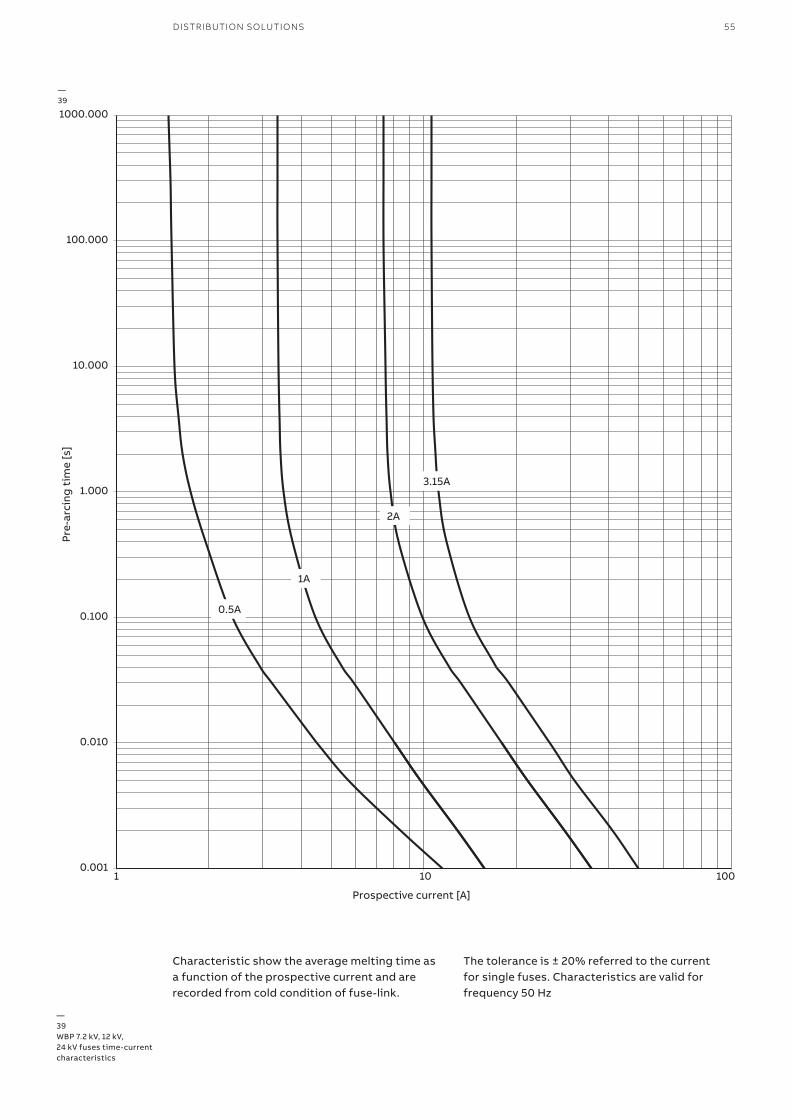
DISTRIBUTION SOLUTIONS 55DISTRIBUTION SOLUTIONS
Characteristic show the average melting time asa function of the prospective current and arerecorded from cold condition of fuse-link.
The tolerance is ± 20% referred to the currentfor single fuses. Characteristics are valid forfrequency 50 Hz
—39WBP 7.2 kV, 12 kV,24 kV fuses time-currentcharacteristics
—39
0.001
0.010
0.100
1.000
10.000
100.000
1000.000
1 10 100
Pre-
arci
ng t
ime
[s]
Prospective current [A]
2A
0.5A
1A
3.15A
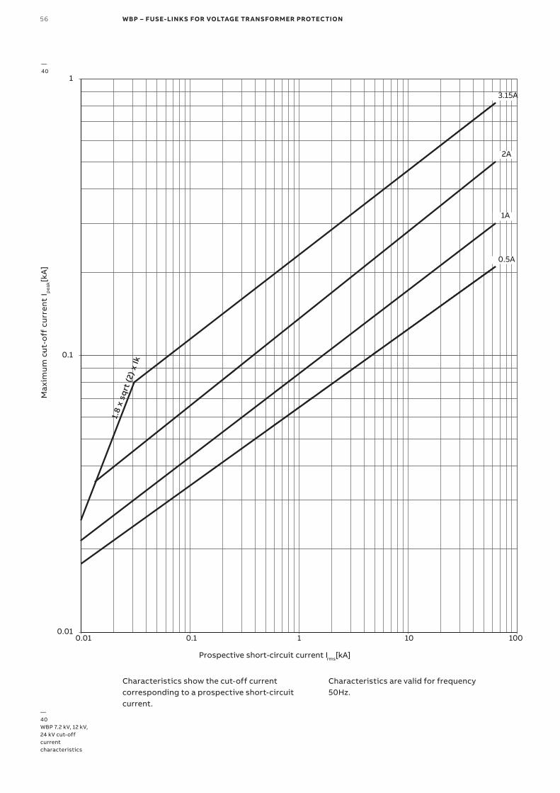
56 WBP – FUSE-LINKS FOR VOLTAGE TRANSFORMER PROTECTION
0.01
0.1
1
0.01 0.1 1 10 100
Max
imum
cut
-off
cur
ren
t I
1.8
x sq
rt (2
) x Ik
pea
k[kA
]-
Prospective short-circuit current Irms[kA]
0.5A
1A
2A
3.15A
Characteristics show the cut-off currentcorresponding to a prospective short-circuitcurrent.
Characteristics are valid for frequency50Hz.
—40WBP 7.2 kV, 12 kV,24 kV cut-offcurrentcharacteristics
—40

DISTRIBUTION SOLUTIONS 57
0.001
0.010
0.100
1.000
10.000
100.000
1000.000
1 10 100
Pre-
arci
ng t
ime
[s]
Prospective current [A]
2A
3.15A
0.5A
1A
4 A
Characteristic show the average melting time asa function of the prospective current and arerecorded from cold condition of fuse-link.
The tolerance is ± 20% referred to the currentfor single fuses. Characteristics are valid forfrequency 50 HZ
—41WBP 36 kV, 40.5kV fuses time-currentcharacteristics
—41
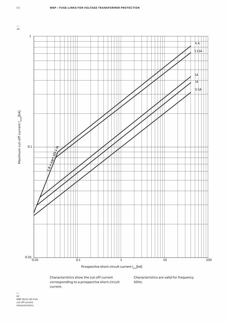
58 WBP – FUSE-LINKS FOR VOLTAGE TRANSFORMER PROTECTION
0.01
0.1
1
0.01 0.1 1 10 100
Max
imum
cut
-off
cur
rent
I pea
k[kA
]
Prospective short-circuit current Irms[kA]
0.5A
1A
2A
3.15A
4 A1.
8 x
sqrt
(2) x
Ik
Characteristics show the cut-off currentcorresponding to a prospective short-circuitcurrent.
Characteristics are valid for frequency50Hz.
—42WBP 36 kV, 40.5 kV, cut-off currentcharacteristics
—42

DISTRIBUTION SOLUTIONS 59

60 FUSE-BASES AND ACCESSORIES
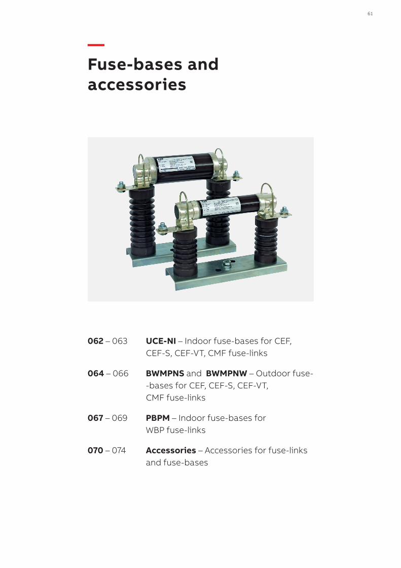
DISTRIBUTION SOLUTIONS 61
062 – 063 UCE-NI – Indoor fuse-bases for CEF, CEF-S, CEF-VT, CMF fuse-links
064 – 066 BWMPNS and BWMPNW – Outdoor fuse- -bases for CEF, CEF-S, CEF-VT, CMF fuse-links
067 – 069 PBPM – Indoor fuse-bases for WBP fuse-links
070 – 074 Accessories – Accessories for fuse-links and fuse-bases
— Fuse-bases and accessories
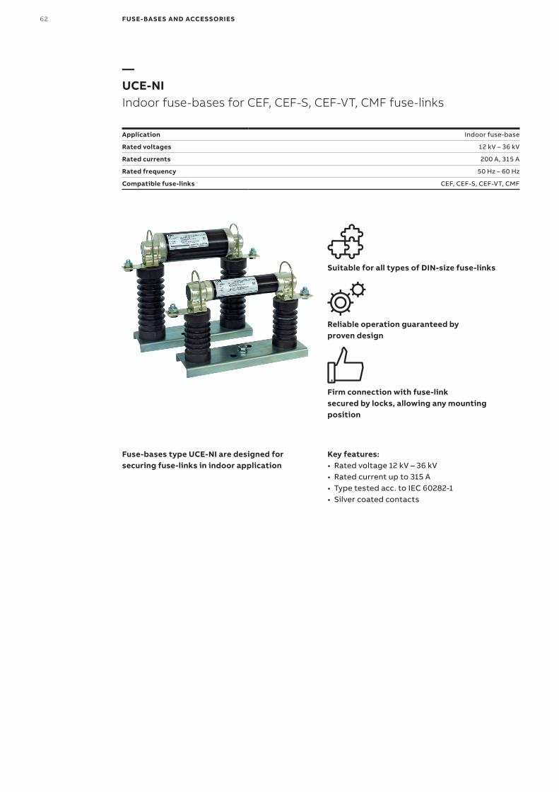
62 FUSE-BASES AND ACCESSORIES
—UCE-NIIndoor fuse-bases for CEF, CEF-S, CEF-VT, CMF fuse-links
Application Indoor fuse-base
Rated voltages 12 kV – 36 kV
Rated currents 200 A, 315 A
Rated frequency 50 Hz – 60 Hz
Compatible fuse-links CEF, CEF-S, CEF-VT, CMF
Suitable for all types of DIN-size fuse-links
Reliable operation guaranteed byproven design
Firm connection with fuse-linksecured by locks, allowing any mounting position
Fuse-bases type UCE-NI are designed for securing fuse-links in indoor application
Key features:• Rated voltage 12 kV – 36 kV• Rated current up to 315 A• Type tested acc. to IEC 60282-1• Silver coated contacts
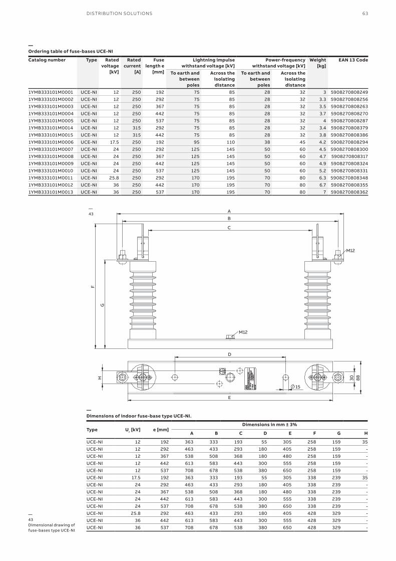
DISTRIBUTION SOLUTIONS 63
—Ordering table of fuse-bases UCE-NI
Catalog number Type Rated voltage
[kV]
Rated current
[A]
Fuse length e
[mm]
Lightning impulsewithstand voltage [kV]
Power-frequencywithstand voltage [kV]
Weight[kg]
EAN 13 Code
To earth and between
poles
Across the isolating distance
To earth and between
poles
Across the isolating distance
1YMB333101M0001 UCE-NI 12 250 192 75 85 28 32 3 59082708082491YMB333101M0002 UCE-NI 12 250 292 75 85 28 32 3.3 59082708082561YMB333101M0003 UCE-NI 12 250 367 75 85 28 32 3.5 59082708082631YMB333101M0004 UCE-NI 12 250 442 75 85 28 32 3.7 59082708082701YMB333101M0005 UCE-NI 12 250 537 75 85 28 32 4 59082708082871YMB333101M0014 UCE-NI 12 315 292 75 85 28 32 3.4 59082708083791YMB333101M0015 UCE-NI 12 315 442 75 85 28 32 3.8 59082708083861YMB333101M0006 UCE-NI 17.5 250 192 95 110 38 45 4.2 59082708082941YMB333101M0007 UCE-NI 24 250 292 125 145 50 60 4.5 59082708083001YMB333101M0008 UCE-NI 24 250 367 125 145 50 60 4.7 59082708083171YMB333101M0009 UCE-NI 24 250 442 125 145 50 60 4.9 59082708083241YMB333101M0010 UCE-NI 24 250 537 125 145 50 60 5.2 59082708083311YMB333101M0011 UCE-NI 25.8 250 292 170 195 70 80 6.3 59082708083481YMB333101M0012 UCE-NI 36 250 442 170 195 70 80 6.7 59082708083551YMB333101M0013 UCE-NI 36 250 537 170 195 70 80 7 5908270808362
—43Dimensional drawing of fuse-bases type UCE-NI
C
B
A
F
G
M12
M12
D
E
88
30
15
H
—Dimensions of indoor fuse-base type UCE-NI.
Type Ur [kV] e [mm]Dimensions in mm ± 3%
A B C D E F G H
UCE-NI 12 192 363 333 193 55 305 258 159 35UCE-NI 12 292 463 433 293 180 405 258 159 -UCE-NI 12 367 538 508 368 180 480 258 159 -UCE-NI 12 442 613 583 443 300 555 258 159 -UCE-NI 12 537 708 678 538 380 650 258 159 -UCE-NI 17.5 192 363 333 193 55 305 338 239 35UCE-NI 24 292 463 433 293 180 405 338 239 -UCE-NI 24 367 538 508 368 180 480 338 239 -UCE-NI 24 442 613 583 443 300 555 338 239 -UCE-NI 24 537 708 678 538 380 650 338 239 -UCE-NI 25.8 292 463 433 293 180 405 428 329 -UCE-NI 36 442 613 583 443 300 555 428 329 -UCE-NI 36 537 708 678 538 380 650 428 329 -
—43
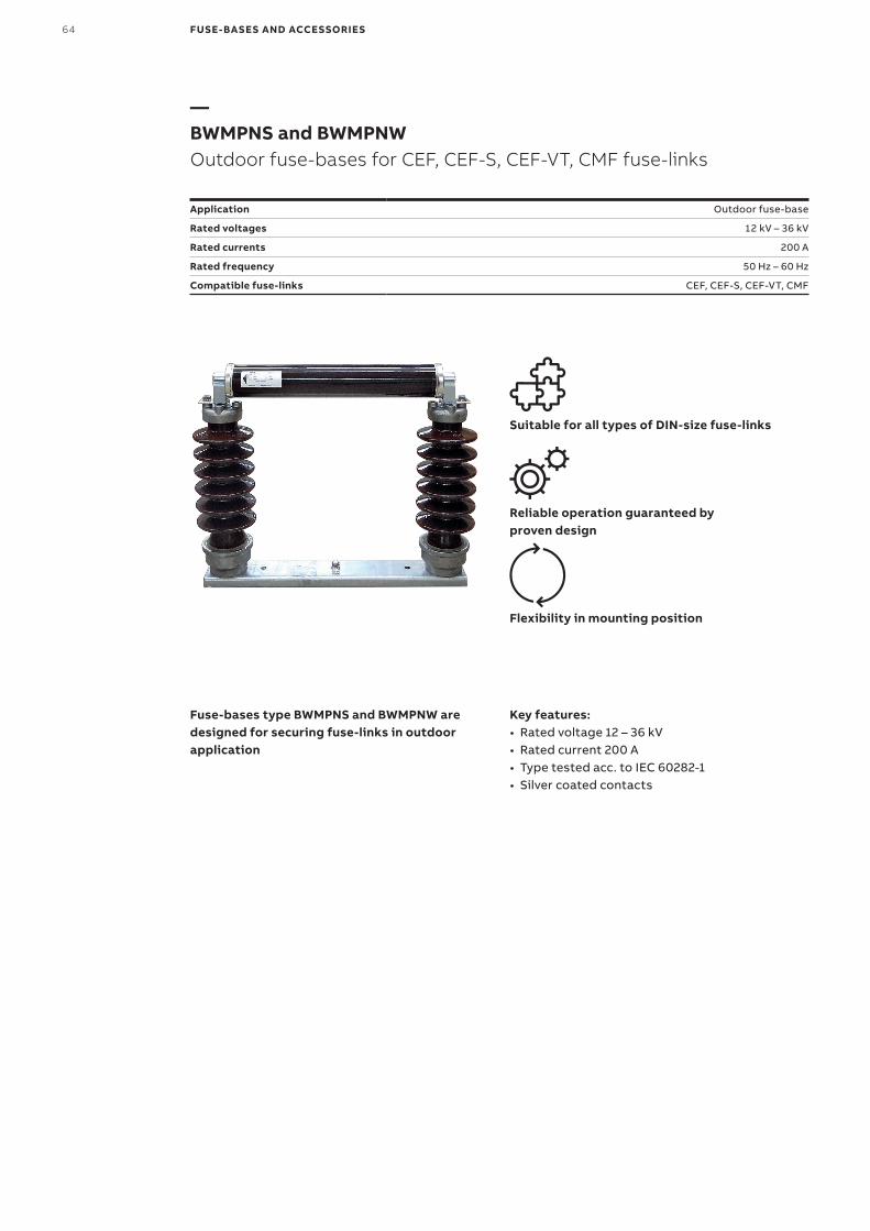
64 FUSE-BASES AND ACCESSORIES
—BWMPNS and BWMPNWOutdoor fuse-bases for CEF, CEF-S, CEF-VT, CMF fuse-links
Application Outdoor fuse-base
Rated voltages 12 kV – 36 kV
Rated currents 200 A
Rated frequency 50 Hz – 60 Hz
Compatible fuse-links CEF, CEF-S, CEF-VT, CMF
Suitable for all types of DIN-size fuse-links
Reliable operation guaranteed byproven design
Flexibility in mounting position
Fuse-bases type BWMPNS and BWMPNW are designed for securing fuse-links in outdoor application
Key features:• Rated voltage 12 – 36 kV• Rated current 200 A• Type tested acc. to IEC 60282-1• Silver coated contacts
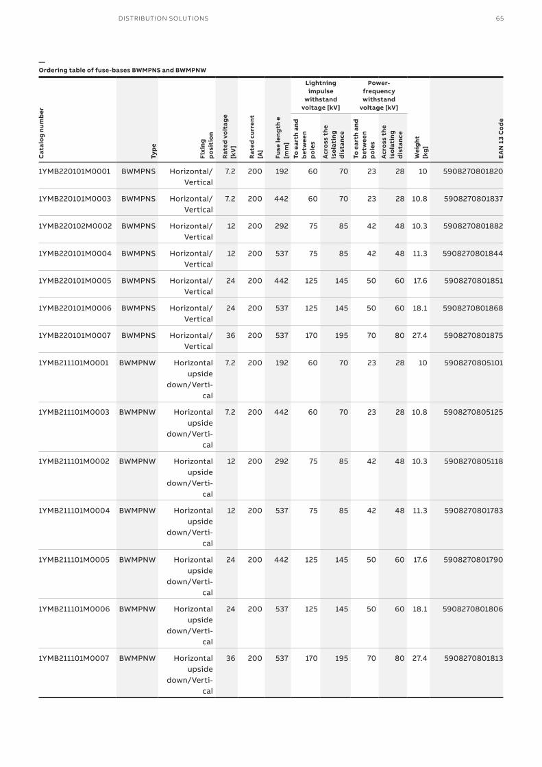
DISTRIBUTION SOLUTIONS 65
—Ordering table of fuse-bases BWMPNS and BWMPNW
Cat
alo
g nu
mb
er
Typ
e
Fixi
ngp
osi
tio
n
Rat
ed v
olt
age
[kV
]
Rat
ed c
urre
nt[A
]
Fuse
leng
th e
[mm
]
Lightning impulse
withstand voltage [kV]
Power-frequencywithstand
voltage [kV]
Wei
ght
[kg
]
EA
N 1
3 C
od
e
To e
arth
and
b
etw
een
po
les
Acr
oss
the
is
ola
ting
d
ista
nce
To e
arth
and
b
etw
een
po
les
Acr
oss
the
is
ola
ting
d
ista
nce
1YMB220101M0001 BWMPNS Horizontal/Vertical
7.2 200 192 60 70 23 28 10 5908270801820
1YMB220101M0003 BWMPNS Horizontal/Vertical
7.2 200 442 60 70 23 28 10.8 5908270801837
1YMB220102M0002 BWMPNS Horizontal/Vertical
12 200 292 75 85 42 48 10.3 5908270801882
1YMB220101M0004 BWMPNS Horizontal/Vertical
12 200 537 75 85 42 48 11.3 5908270801844
1YMB220101M0005 BWMPNS Horizontal/Vertical
24 200 442 125 145 50 60 17.6 5908270801851
1YMB220101M0006 BWMPNS Horizontal/Vertical
24 200 537 125 145 50 60 18.1 5908270801868
1YMB220101M0007 BWMPNS Horizontal/Vertical
36 200 537 170 195 70 80 27.4 5908270801875
1YMB211101M0001 BWMPNW Horizontal upside
down/Verti-cal
7.2 200 192 60 70 23 28 10 5908270805101
1YMB211101M0003 BWMPNW Horizontal upside
down/Verti-cal
7.2 200 442 60 70 23 28 10.8 5908270805125
1YMB211101M0002 BWMPNW Horizontal upside
down/Verti-cal
12 200 292 75 85 42 48 10.3 5908270805118
1YMB211101M0004 BWMPNW Horizontal upside
down/Verti-cal
12 200 537 75 85 42 48 11.3 5908270801783
1YMB211101M0005 BWMPNW Horizontal upside
down/Verti-cal
24 200 442 125 145 50 60 17.6 5908270801790
1YMB211101M0006 BWMPNW Horizontal upside
down/Verti-cal
24 200 537 125 145 50 60 18.1 5908270801806
1YMB211101M0007 BWMPNW Horizontal upside
down/Verti-cal
36 200 537 170 195 70 80 27.4 5908270801813
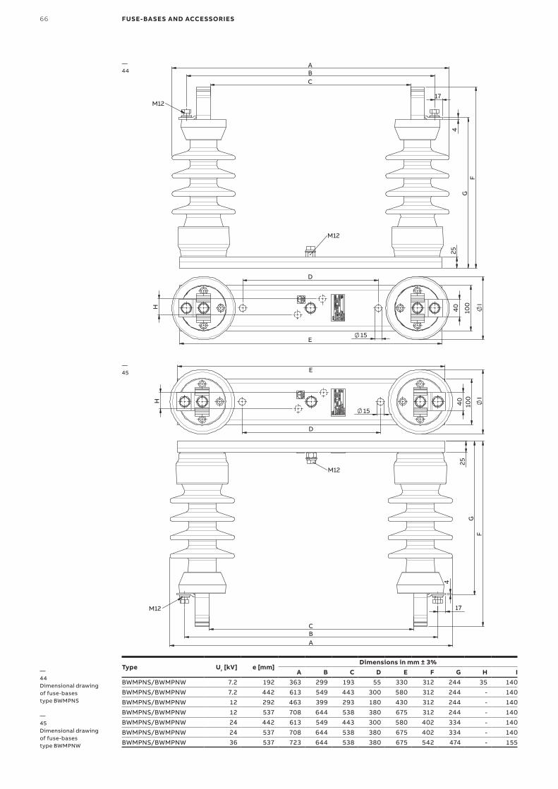
66 FUSE-BASES AND ACCESSORIES
—44Dimensional drawing of fuse-bases type BWMPNS
—45Dimensional drawing of fuse-bases type BWMPNW
—44
—45
C B
F
G
4
17
25
A
M12
M12
D
10
0
40
15 E
I
H
A B C
G
F
4
17
25 M12
M12
D
E
15
I
40
1
00
H
Type Ur [kV] e [mm]Dimensions in mm ± 3%
A B C D E F G H IBWMPNS/BWMPNW 7.2 192 363 299 193 55 330 312 244 35 140BWMPNS/BWMPNW 7.2 442 613 549 443 300 580 312 244 - 140BWMPNS/BWMPNW 12 292 463 399 293 180 430 312 244 - 140BWMPNS/BWMPNW 12 537 708 644 538 380 675 312 244 - 140BWMPNS/BWMPNW 24 442 613 549 443 300 580 402 334 - 140BWMPNS/BWMPNW 24 537 708 644 538 380 675 402 334 - 140BWMPNS/BWMPNW 36 537 723 644 538 380 675 542 474 - 155
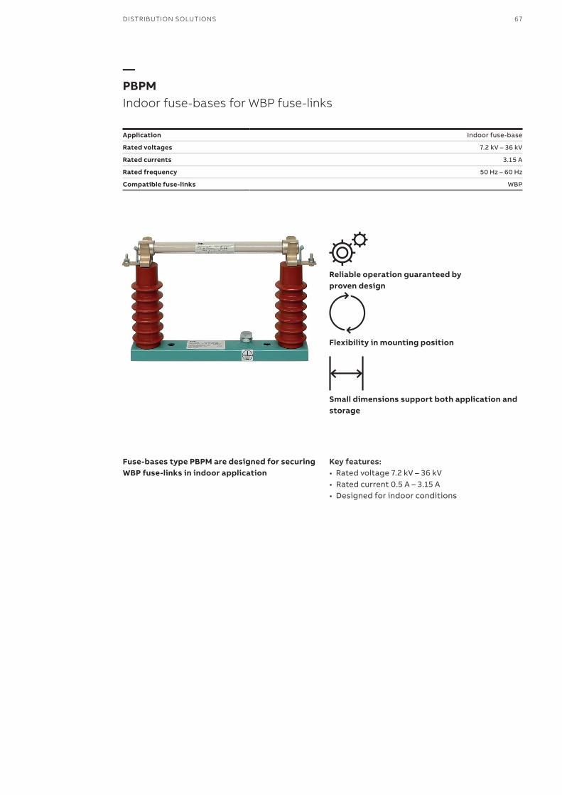
DISTRIBUTION SOLUTIONS 67
—PBPMIndoor fuse-bases for WBP fuse-links
Application Indoor fuse-base
Rated voltages 7.2 kV – 36 kV
Rated currents 3.15 A
Rated frequency 50 Hz – 60 Hz
Compatible fuse-links WBP
Reliable operation guaranteed byproven design
Flexibility in mounting position
Small dimensions support both application and storage
Fuse-bases type PBPM are designed for securing WBP fuse-links in indoor application
Key features:• Rated voltage 7.2 kV – 36 kV• Rated current 0.5 A – 3.15 A• Designed for indoor conditions
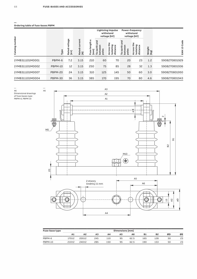
68 FUSE-BASES AND ACCESSORIES
—Ordering table of fuse-bases PBPM
Cat
alo
g nu
mb
er
Typ
e
Rat
ed v
olt
age
[kV
]
Rat
ed c
urre
nt[A
]
Fuse
leng
th e
[mm
]
Lightning impulsewithstand
voltage [kV]
Power-frequencywithstand
voltage [kV]
Wei
ght
[kg
]
EA
N 1
3 C
od
e
To e
arth
and
b
etw
een
po
les
Acr
oss
the
is
ola
ting
d
ista
nce
To e
arth
and
b
etw
een
po
les
Acr
oss
the
is
ola
ting
d
ista
nce
1YMB311101M0001 PBPM-6 7.2 3.15 210 60 70 20 23 1.2 5908270801929
1YMB311101M0002 PBPM-10 12 3.15 250 75 85 28 32 1.3 5908270801936
1YMB311101M0007 PBPM-20 24 3.15 310 125 145 50 60 3.0 5908270801950
1YMB311101M0004 PBPM-30 36 3.15 385 170 195 70 80 4.6 5908270801943
—46Dimensional drawings of fuse-bases type PBPM-6, PBPM-10 A1
A2
A3
M5
02
øE
M10
2
1B
2B
A5
A6
A4
øD0
4
51
2 otwory średnicy 11 mm
Fuse-base type Dimensions [mm]A1 A2 A3 A4 A5 A6 B1 B2 ØD ØE
PBPM-6 170±2 200±2 245 110 95 62.5 165 128 50 23
PBPM-10 210±2 240±2 285 150 95 62.5 190 153 50 23
—46
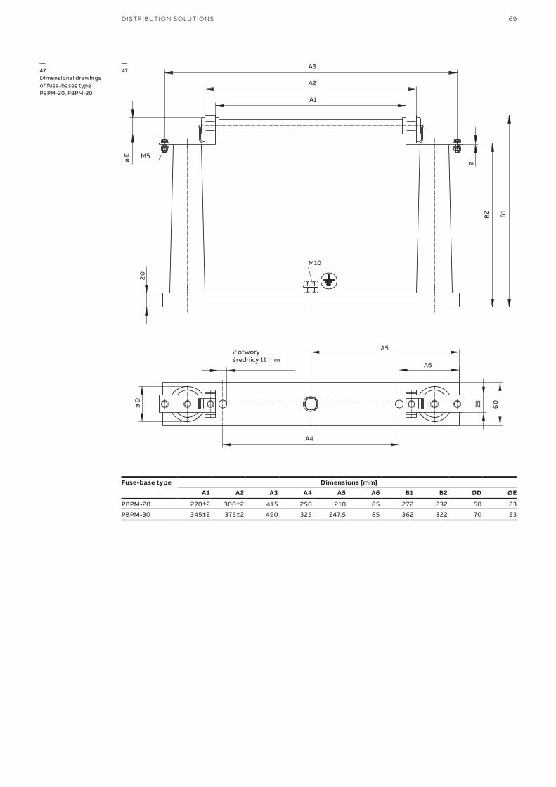
DISTRIBUTION SOLUTIONS 69
A1
A2
A3
øE M5
02
M10
2
2B
1B
øD 0
6
52
A5
A6
A4
2 otworyśrednicy 11 mm
—47Dimensional drawings of fuse-bases type PBPM-20, PBPM-30
—47
Fuse-base type Dimensions [mm]A1 A2 A3 A4 A5 A6 B1 B2 ØD ØE
PBPM-20 270±2 300±2 415 250 210 85 272 232 50 23
PBPM-30 345±2 375±2 490 325 247.5 85 362 322 70 23
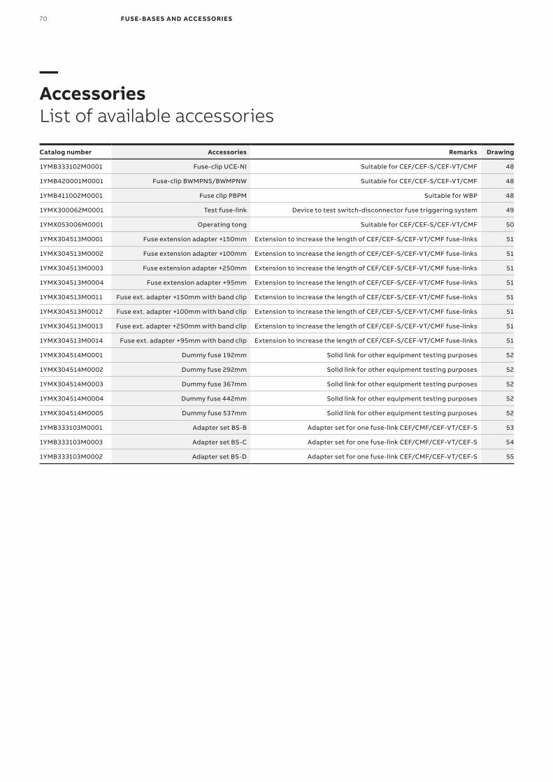
70 FUSE-BASES AND ACCESSORIES
—AccessoriesList of available accessories
Catalog number Accessories Remarks Drawing
1YMB333102M0001 Fuse-clip UCE-NI Suitable for CEF/CEF-S/CEF-VT/CMF 48
1YMB420001M0001 Fuse-clip BWMPNS/BWMPNW Suitable for CEF/CEF-S/CEF-VT/CMF 48
1YMB411002M0001 Fuse clip PBPM Suitable for WBP 48
1YMX300062M0001 Test fuse-link Device to test switch-disconnector fuse triggering system 49
1YMX053006M0001 Operating tong Suitable for CEF/CEF-S/CEF-VT/CMF 50
1YMX304513M0001 Fuse extension adapter +150mm Extension to increase the length of CEF/CEF-S/CEF-VT/CMF fuse-links 51
1YMX304513M0002 Fuse extension adapter +100mm Extension to increase the length of CEF/CEF-S/CEF-VT/CMF fuse-links 51
1YMX304513M0003 Fuse extension adapter +250mm Extension to increase the length of CEF/CEF-S/CEF-VT/CMF fuse-links 51
1YMX304513M0004 Fuse extension adapter +95mm Extension to increase the length of CEF/CEF-S/CEF-VT/CMF fuse-links 51
1YMX304513M0011 Fuse ext. adapter +150mm with band clip Extension to increase the length of CEF/CEF-S/CEF-VT/CMF fuse-links 51
1YMX304513M0012 Fuse ext. adapter +100mm with band clip Extension to increase the length of CEF/CEF-S/CEF-VT/CMF fuse-links 51
1YMX304513M0013 Fuse ext. adapter +250mm with band clip Extension to increase the length of CEF/CEF-S/CEF-VT/CMF fuse-links 51
1YMX304513M0014 Fuse ext. adapter +95mm with band clip Extension to increase the length of CEF/CEF-S/CEF-VT/CMF fuse-links 51
1YMX304514M0001 Dummy fuse 192mm Solid link for other equipment testing purposes 52
1YMX304514M0002 Dummy fuse 292mm Solid link for other equipment testing purposes 52
1YMX304514M0003 Dummy fuse 367mm Solid link for other equipment testing purposes 52
1YMX304514M0004 Dummy fuse 442mm Solid link for other equipment testing purposes 52
1YMX304514M0005 Dummy fuse 537mm Solid link for other equipment testing purposes 52
1YMB333103M0001 Adapter set BS-B Adapter set for one fuse-link CEF/CMF/CEF-VT/CEF-S 53
1YMB333103M0003 Adapter set BS-C Adapter set for one fuse-link CEF/CMF/CEF-VT/CEF-S 54
1YMB333103M0002 Adapter set BS-D Adapter set for one fuse-link CEF/CMF/CEF-VT/CEF-S 55
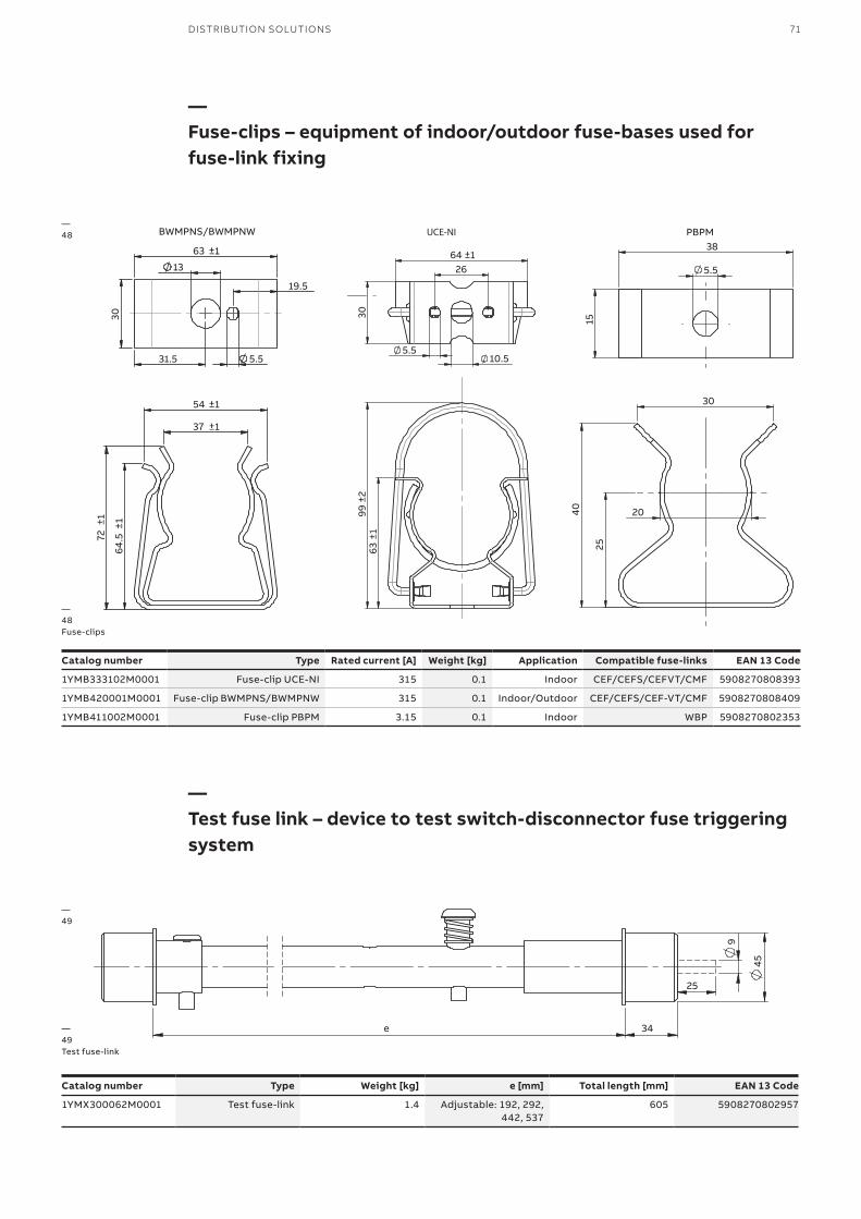
DISTRIBUTION SOLUTIONS 71
—Fuse-clips – equipment of indoor/outdoor fuse-bases used for fuse-link fixing
—Test fuse link – device to test switch-disconnector fuse triggering system
40
30
25
20
38
15
5.5
PBPM
Catalog number Type Rated current [A] Weight [kg] Application Compatible fuse-links EAN 13 Code
1YMB333102M0001 Fuse-clip UCE-NI 315 0.1 Indoor CEF/CEFS/CEFVT/CMF 5908270808393
1YMB420001M0001 Fuse-clip BWMPNS/BWMPNW 315 0.1 Indoor/Outdoor CEF/CEFS/CEF-VT/CMF 5908270808409
1YMB411002M0001 Fuse-clip PBPM 3.15 0.1 Indoor WBP 5908270802353
45
9
25
34 e
Catalog number Type Weight [kg] e [mm] Total length [mm] EAN 13 Code
1YMX300062M0001 Test fuse-link 1.4 Adjustable: 192, 292, 442, 537
605 5908270802957
—49Test fuse-link
—48
—49
99
±2
63
±1
30
5.5
64 ±1 26
10.5
UCE-NI
37 ±1
54 ±1
64.
5 ±1
72
±1
13
5.5
63
BWMPNS/BWMPNW
±1
30
31.5
19.5
—48Fuse-clips
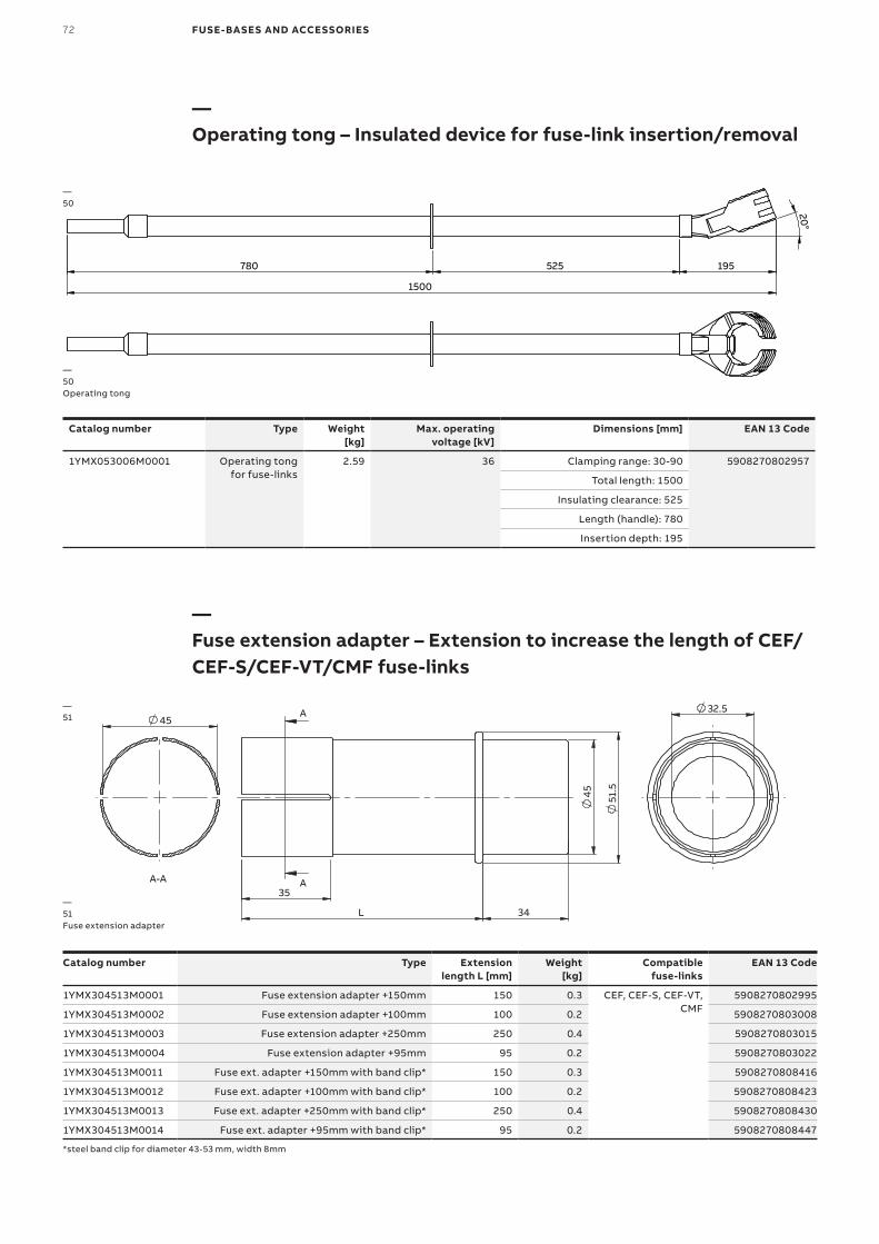
72 FUSE-BASES AND ACCESSORIES
—Operating tong – Insulated device for fuse-link insertion/removal
—Fuse extension adapter – Extension to increase the length of CEF/CEF-S/CEF-VT/CMF fuse-links
20°
1500
780 525 195
Catalog number Type Weight [kg]
Max. operating voltage [kV]
Dimensions [mm] EAN 13 Code
1YMX053006M0001 Operating tong for fuse-links
2.59 36 Clamping range: 30-90 5908270802957
Total length: 1500
Insulating clearance: 525
Length (handle): 780
Insertion depth: 195
L
45
51
.5
34
35
A
A
45
A-A
32.5
Catalog number Type Extension length L [mm]
Weight [kg]
Compatible fuse-links
EAN 13 Code
1YMX304513M0001 Fuse extension adapter +150mm 150 0.3 CEF, CEF-S, CEF-VT, CMF
5908270802995
1YMX304513M0002 Fuse extension adapter +100mm 100 0.2 5908270803008
1YMX304513M0003 Fuse extension adapter +250mm 250 0.4 5908270803015
1YMX304513M0004 Fuse extension adapter +95mm 95 0.2 5908270803022
1YMX304513M0011 Fuse ext. adapter +150mm with band clip* 150 0.3 5908270808416
1YMX304513M0012 Fuse ext. adapter +100mm with band clip* 100 0.2 5908270808423
1YMX304513M0013 Fuse ext. adapter +250mm with band clip* 250 0.4 5908270808430
1YMX304513M0014 Fuse ext. adapter +95mm with band clip* 95 0.2 5908270808447
*steel band clip for diameter 43-53 mm, width 8mm
—50Operating tong
—50
—51Fuse extension adapter
—51
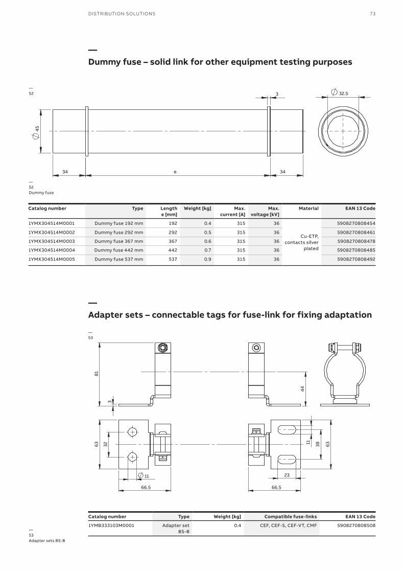
DISTRIBUTION SOLUTIONS 73
—Dummy fuse – solid link for other equipment testing purposes
—Adapter sets – connectable tags for fuse-link for fixing adaptation
45
e 34 34
3 32.5 —52
—52Dummy fuse
Catalog number Type Length e [mm]
Weight [kg] Max. current [A]
Max. voltage [kV]
Material EAN 13 Code
1YMX304514M0001 Dummy fuse 192 mm 192 0.4 315 36
Cu-ETP, contacts silver
plated
5908270808454
1YMX304514M0002 Dummy fuse 292 mm 292 0.5 315 36 5908270808461
1YMX304514M0003 Dummy fuse 367 mm 367 0.6 315 36 5908270808478
1YMX304514M0004 Dummy fuse 442 mm 442 0.7 315 36 5908270808485
1YMX304514M0005 Dummy fuse 537 mm 537 0.9 315 36 5908270808492
3
81
44
63
32
11
66.5
23
66.5
63
38 11
3
81
44
BS-C
63
38
11
66.5
15
66.5
63
38 11
3
81
25
44
63
38
11
77.5
23
38 11
63
77.5
BS-B
BS-D
Catalog number Type Weight [kg] Compatible fuse-links EAN 13 Code
1YMB333103M0001 Adapter set BS-B
0.4 CEF, CEF-S, CEF-VT, CMF 5908270808508
—53
—53Adapter sets BS-B
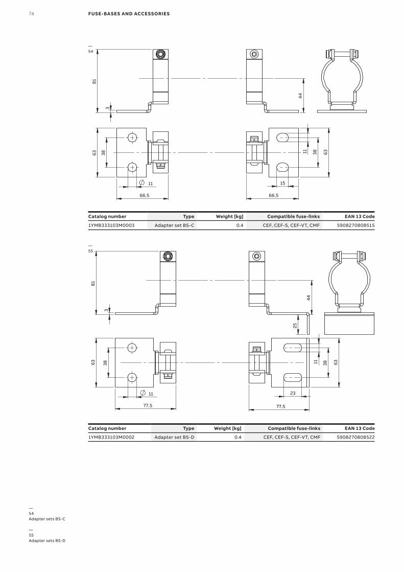
74 FUSE-BASES AND ACCESSORIES
3
81
44
63
32
11
66.5
23
66.5
63
38 11
3
81
44
BS-C
63
38
11
66.5
15
66.5
63
38 11
3
81
25
44
63
38
11
77.5
23
38 11
63
77.5
BS-B
BS-D
3
81
44
63
32
11
66.5
23
66.5
63
38 11
3
81
44
BS-C
63
38
11
66.5
15
66.5
63
38 11
3
81
25
44
63
38
11
77.5
23
38 11
63
77.5
BS-B
BS-D
—54
—54Adapter sets BS-C
—55Adapter sets BS-D
Catalog number Type Weight [kg] Compatible fuse-links EAN 13 Code
1YMB333103M0003 Adapter set BS-C 0.4 CEF, CEF-S, CEF-VT, CMF 5908270808515
—55
Catalog number Type Weight [kg] Compatible fuse-links EAN 13 Code
1YMB333103M0002 Adapter set BS-D 0.4 CEF, CEF-S, CEF-VT, CMF 5908270808522

DISTRIBUTION SOLUTIONS 75
240
1PL
1613
-W1-
en. E
dit
ion
02.
2020
We reserve the right to make technical changes or modify the contents of this document without prior notice. With regard to purchase orders, the agreed particulars shall prevail. ABB does not accept any responsibility whatsoever for potential errors or possible lack of information in this document.We reserve all rights in this document and in the subject matter and illustrations contained therein. Any reproduction, disclosure to third parties or utilization of its contents – in whole or in parts – is forbidden without prior written consent of ABB.
© Copyright 2020 ABB All rights reserved
—ABB Contact Centertel.: +48 22 22 37 777e-mail: [email protected]
ABB Sp. z o.o.Branch in Przasnysz59 Leszno St.06-300 Przasnysz, PolandPhone: +48 22 22 38 900 Fax: +48 22 22 38 950
www.abb.com


