Embed Size (px)
Citation preview
Computers and Electrical Engineering xxx (2014) xxx–xxx
Contents lists available at ScienceDirect
Computers and Electrical Engineering
journal homepage: www.elsevier .com/ locate/compeleceng
Distributed topology discovery in self-assembled nanonetwork-on-chip q
http://dx.doi.org/10.1016/j.compeleceng.2014.09.0030045-7906/� 2014 Elsevier Ltd. All rights reserved.
q Reviews processed and recommended for publication to the Editor-in-Chief by Guest Editor Dr. Masoud Daneshtalab.⇑ Corresponding author.
E-mail addresses: [email protected] (V. Catania), [email protected] (A. Mineo), salvatore.monteleone@diee(S. Monteleone), [email protected] (D. Patti).
Please cite this article in press as: Catania V et al. Distributed topology discovery in self-assembled nano network-on-chip. CompuEng (2014), http://dx.doi.org/10.1016/j.compeleceng.2014.09.003
Vincenzo Catania, Andrea Mineo, Salvatore Monteleone, Davide Patti ⇑DIEEI, University of Catania, V.le Andrea Doria 6, 95125 Catania, Italy
a r t i c l e i n f o
Article history:Received 24 February 2014Received in revised form 12 September 2014Accepted 12 September 2014Available online xxxx
Keywords:NanotechnologyDNASelf-assemblyRoutingDeadlock
a b s t r a c t
In this paper, we present DiSR, a distributed approach to topology discovery and defectmapping in a self-assembled nano network-on-chip. The main aim is to achieve thealready-proven properties of segment-based deadlock freedom requiring neither atopology graph as input, nor a centralized algorithm to configure network paths. Afterintroducing the conceptual elements and the execution model of DiSR, we show how theopen-source Nanoxim platform has been used to evaluate the proposed approach in theprocess of discovering irregular network topology while establishing network segments.Comparison against a tree-based approach shows how DiSR still preserves some importantproperties (coverage, defect tolerance, scalability) while avoiding resource hungry solu-tions such as virtual channels and hardware redundancy. Finally, we propose a gate-levelhardware implementation of the required control logic and storage for DiSR, demonstrat-ing a relatively acceptable impact ranging from 10 to about 20% of the budget of transistorsavailable for each node.
� 2014 Elsevier Ltd. All rights reserved.
1. Introduction and motivation
Exploring long-term alternatives to the CMOS technology is gaining more and more relevance as the scaling trend of suchdevices keeps introducing new challenges: power density, defect tolerance, testing costs and wire delays are only a few ofthe many critical aspects involved [1]. While software parallelism and multicore approaches [2,3] are partially mitigating theimpact of such constraints on performances, it is likely that a growing computing demand will eventually need even moreradical architectural modifications and paradigm shifts to address the Computer Design challenges of the upcoming decades.
In recent years, self-assembled nanoscale architectures [4] emerged as a promising technology due their tera/peta scale ofintegration, defect tolerance and huge potential computing capabilities. These technologies are certainly still at their earlystage of development; however, different laboratory demos and proofs-of-concept have been presented [5,6]. For a completesurvey on self-assembled architectures and how they compare against classical many-core systems in terms of technologies,fault tolerance, performance and software tools see also [7]. The main idea behind this approach is exploiting the physicalregularity and stability of DNA structures in order to create a scaffold onto which nano-devices (e.g. nanowires and CNFETs[8,9]) can be attached. This can be achieved by designing appropriate complementary DNA tags for each terminal to be
i.unict.it
t Electr

2 V. Catania et al. / Computers and Electrical Engineering xxx (2014) xxx–xxx
placed, so that a nano device will be attached only where its own DNA tag matches a complementary tag on the DNA gridscaffold (see Fig. 1a). Of course, a detailed description of the chemical properties involved is far beyond the scope of thispaper (see also [10]).
In this work, we present DiSR (Distributed Segment Routing), a distributed approach focused on addressing the threemain challenges that this new fabrication process introduces in nanoscale Network-on-Chip Design: (i) limited node complex-ity, (ii) large scale randomness and (iii) high defect rates. The limited node complexity aspect is directly related to the use ofcomplementary DNA tags in order to place circuit components. The traditional CMOS process introduces complexity withlarger photolithography masks: more complex (larger) circuits will only require larger masks. Conversely, a self-assemblyprocess achieves complexity by increasing the number of unique DNA tags, since having more different tags means havingmore control on component placement. Ideally, by specifying a single and unique tag for each nano device terminal, we couldexactly choose where each component would be placed in the design, but the number of DNA symbols forming the DNAsequence is limited (sequence of 4 nucleobases G, A, T, C) and so creating many different tags (of a predetermined length)would mean making them more similar to each other, increasing the probability of incorrect/partial matching. To avoid thisproblem, the number of unique tags must be limited, which limits also the complexity available at each node. In this work, abudget of about 10,000 CNFETs per node has been assumed, as estimated in [11]. Large scale randomness is the other funda-mental condition of self-assembled technology: DNA tags allow controlled placement inside the node grid, but there is nocontrol over the placement of these grids in the whole network. As a consequence, other typical properties of regular net-works cannot be guaranteed, e.g. being connected to a fixed number of neighbors, having a determined orientation andso on. Finally, defect rates: while they are hardly tolerated in mask-based top-down design, the same nature of a bottom-up self-assembly process cannot assume such a deterministic device placement process, thus defect tolerance is more adesign requirement than an exception to be avoided.
These aspects of a DNA self-assembly process lead to some important implications to be addressed when approaching tothe design of a nanoscale Network-on-Chip architecture: computational model should be based on a distributed network ofsmall processing and storage nodes, randomly placed and interconnected (see Fig. 1b). Proof-of-concept of such architecturescan be found for example in [5], where instruction and data operands are moved around the network in order to be pro-cessed. In addition, independently of the particular policy chosen to route instruction and data packets, such networks mustbe able to guarantee deadlock freedom without any prior assumption about the topology.
In this work, we introduce DiSR, a Distributed Segment-based approach to topology discovery and deadlock freedom inlarge scale DNA self-assembled on chip networks. Our contribution aims to achieve the classical properties of a segment-based approach [12] without requiring any topology graph, external defect map or centralized algorithm execution. The DiSR
approach is not intended to discover the ‘‘optimal’’ segment choice (ideally reachable with the knowledge of the topologygraph) but just to demonstrate a concrete model that can fit into such complex, irregular and large sized networks. It isimportant to underline that, although we can assume as background an architecture similar to the one depicted in Fig. 1,
(a) (b)
Fig. 1. (a) Strands of complementary DNA tags self assemble to generate larger structures. (b) The resulting irregular topology of processing (P) and storage(M) elements.
Please cite this article in press as: Catania V et al. Distributed topology discovery in self-assembled nano network-on-chip. Comput ElectrEng (2014), http://dx.doi.org/10.1016/j.compeleceng.2014.09.003
V. Catania et al. / Computers and Electrical Engineering xxx (2014) xxx–xxx 3
the DiSR topology discovery approach presented this work is more general and not strictly dependent on any underlyingcomputational model adopted.
The paper is organized as follows: in Section 2 we summarize the main approaches for topology agnostic deadlock free-dom. Next, in Section 3 are described the main elements and the execution model of the proposed approach. Further detailsabout node behavior in relation to the execution model are provided in Section 4. In Section 5, simulations are carried outwith the open-source tool Nanoxim to demonstrate how DiSR preserves some of the main segment-based properties andhow compares to the tree-based approaches. Finally a draft of an architectural implementation is shown in Section 6 to eval-uate the feasibility of the approach in terms of node complexity.
2. Background and contribution
Several works addressed the problem of topology agnostic deadlock freedom introducing virtual channels [13–15], butwhile they show interesting performances, the low resources available to prevent deadlocks makes them not suitable forthe DNA self-assembled networks we are assuming as scenario. Other topology independent algorithms do not requireany virtual channel but exploit the concept of ‘‘turn prohibition’’. In particular, authors of [16] exploit the creation of a span-ning tree of the topology, placing bidirectional restrictions to avoid that a packet can traverse a given link in both up anddown directions. The hierarchical nature of this approach can lead to an uneven traffic distribution, with many packets tra-versing upper links (near to the root), but this is quite acceptable in classical wide area networks topologies with a limitednumber of nodes. Other approaches such as FX [17] mitigate this issue, but the set of turn restrictions is still prefixed strictlydepending on the particular tree root selected. Other solutions try to approach the issue of irregular topologies by limitingthe number [18,19] or the location [20,21] of missing links. This restriction is clearly unacceptable given the hight-defectrates of DNA self-assembled networks scenario. For the same reason, we also avoid considering solutions based on hard-ware-redundancy to dynamically recover defects as in [22].
In [12] authors present an approach that solves these limitations setting turn restrictions locally, independently fromother restrictions. The whole network is partitioned into segments, and a bidirectional turn restriction can be freely chosenwithin a segment in order to guarantee deadlock freedom while preserving network connectivity. This locality independenceproperty, removing the requirement of choosing a particular tree/root, would make this approach the best choice for thegiven scenario; however, it still requires the knowledge of the whole network graph in order to find the segments.
The DiSR approach presented in this work is a first attempt to achieve the same goals of a segment based turn prohibitionrequiring neither the knowledge of a topology graph nor centralized execution. In particular, DiSR implements segment dis-covery and turn prohibition using a completely different mechanism, based on a distributed exchange of small setup packetsrequiring a limited and scalable portion of the available resource budget. The following main features distinguish DiSR fromclassic approaches to segment partitioning:
� No centralized entity is globally responsible and/or aware of what is going on, i.e. the status of the DiSR execution is col-lectively distributed among the nodes.� No defect map and/or topology graph is used as input, thus, the topology has to be discovered while segments are created.� At the end of the execution, no segment list is created or stored anywhere: each node is only aware of being part of a
segment, ignoring the presence of other nodes in the same segment and also the presence of other segments in thenetwork.
3. DiSR overview
The main concept behind the turn prohibition method we propose in this work is the segment. A segment Sb is basically apath of consecutive nodes and links, starting with a link attached to a node belonging to a different segment Sa and endingwith a link attached to a node of another segment Sc. In other words, a segment is a path connecting two other different seg-ments. The example in Fig. 2 shows the segment with id 1.4, starting with a link connected to the node 9, traversing nodes 4,3, 2 and ending with the link connected to node 1. Other segments depicted are, for example, 9.2 (link from 9, node 10, link tonode 3) and 9.3 (link from 9, node 8, link, node 7, link, node 6, link, node 5, link to node 1). Note also that starting/endinglinks can coincide and a segment can also be formed by one single link (e.g. the case of 7.2 and 5.4). An exception to the rulethat a segment must connect two other segments is the first segment established in the network, called starting segmentwhich is a loop beginning/ending on the same node.
A detailed description of the DiSR execution model as depicted in Fig. 4 will be discussed in SubSection 3.3. Roughlyspeaking, the execution phases consist of:
1. Injection of the DiSR process from an upper layer to set a bootstrap node.2. Broadcasting and confirmation to create the first segment of the subnet.3. Parallel segment requests starting from assigned nodes to discover other segments.4. Processing of resulting segment confirmation/cancel packets.5. Turn prohibition in each confirmed segment.
Please cite this article in press as: Catania V et al. Distributed topology discovery in self-assembled nano network-on-chip. Comput ElectrEng (2014), http://dx.doi.org/10.1016/j.compeleceng.2014.09.003

Fig. 2. Example of segments.
4 V. Catania et al. / Computers and Electrical Engineering xxx (2014) xxx–xxx
This first work is explicitly focused on demonstrating the feasibility and scalability of DiSR in the particular scenarioassumed; for this reason we will not investigate the degree of freedom that the last of the above steps introduces, i.e. choos-ing where to place the restriction in the context of a segment. This choice would strictly depend on the particular routingstrategy that will be used and could result in some interesting improvements. The scope of this work is understandinghow DiSR can implement a distributed topology discovery, mapping defects and creating a segment partitioning that willbe exploited in a second design phase which includes choosing and implementing a routing strategy. For this reason, sincewe can safely assume that a random turn (e.g. the first) can be prohibited once each segment has been confirmed, the lasttwo execution phases will be addressed as one.
3.1. DiSR data structures
We distinct between two different kinds of data stored in each node: Dynamic Behavior Status (DBS) and Local EnvironmentData (LED).
DBS information represent node status and is related to its current execution phase in the context of DiSR. The DBS canhave the following values:
� Free: a node that has not been yet considered by the DiSR algorithm.� Bootstrap: a node which has been explicitly set as bootstrap node from an upper layer via.� ActiveSearching: a node from which a new segments searching process has been started and not yet canceled or
confirmed.� Candidate: a node currently candidate to be part of a segment, but not being itself the node from which the searching
process was started.� CandidateStarting: same as above, but with the node considered as candidate for starting a segment.� Assigned: a node for which the segment has been determined.
LED variables are a kind of instant snapshot of the execution of DiSR algorithm consisting in the following variables:
� segID: a value used to specify the segment to which the node has been assigned or is currently candidate to be part of.� visited: a boolean value. When true then a segID different from NULL specifies the segment to which the node has been
assigned.� tvisited: a boolean value. If true, the node is being considered as candidate for a segment, and the segID value specifies
the segment ID for which the node is candidate.� link_visited[]: an array of values containing information about attached links (segID of the segment owning each link).
When NULL, the corresponding link has not yet been assigned.� link_tvisited[]: an array of values representing information about attached links (segID of the segment for which
the link is candidate). When NULL, the link is not candidate for any segment, i.e. it has already been assigned or itis free.
Please cite this article in press as: Catania V et al. Distributed topology discovery in self-assembled nano network-on-chip. Comput ElectrEng (2014), http://dx.doi.org/10.1016/j.compeleceng.2014.09.003
V. Catania et al. / Computers and Electrical Engineering xxx (2014) xxx–xxx 5
3.2. Message types required
The DiSR approach works with a distributed mechanism which is build upon an exchange of small control packets con-taining the following fields:
� packet_type: encodes the meaning of the control packet.� seg_ID: the id of the segment targeted by the DiSR control message.� src_ID: the id of the node that originated the packet.� TTL: a counter which makes the packet expire after a given number of retries.
With regard to the packet_type field, we can have the following control packets types:
� STARTING_SEGMENT_REQUEST: Injected by the bootstrap node when searching the first segment.� STARTING_SEGMENT_CONFIRM: used when establishing the starting segment.� SEGMENT_REQUEST: used to search candidates for a segment (not the first).� SEGMENT_CONFIRM: used to establish a segment.� SEGMENT_CANCEL: used to cancel the process of searching a segment along a specific link.
A quantitative analysis of the resources needed to implement and manage these structures is presented in Section 6where it is discussed the impact of DiSR control logic and storage on the node’s hardware implementation.
3.3. Execution model
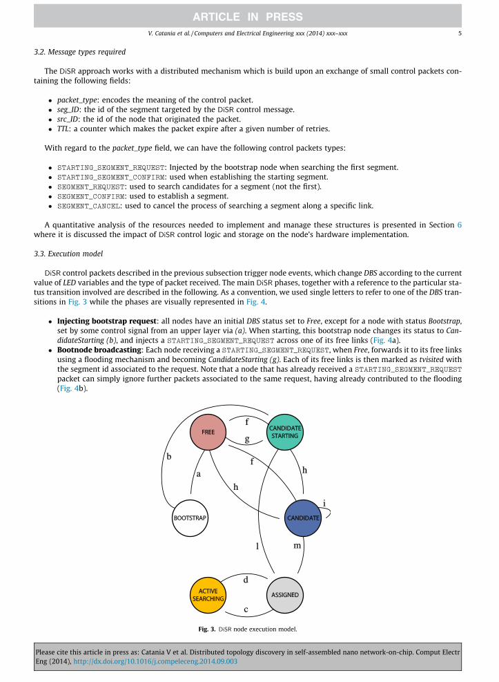
DiSR control packets described in the previous subsection trigger node events, which change DBS according to the currentvalue of LED variables and the type of packet received. The main DiSR phases, together with a reference to the particular sta-tus transition involved are described in the following. As a convention, we used single letters to refer to one of the DBS tran-sitions in Fig. 3 while the phases are visually represented in Fig. 4.
� Injecting bootstrap request: all nodes have an initial DBS status set to Free, except for a node with status Bootstrap,set by some control signal from an upper layer via (a). When starting, this bootstrap node changes its status to Can-didateStarting (b), and injects a STARTING_SEGMENT_REQUEST across one of its free links (Fig. 4a).
� Bootnode broadcasting: Each node receiving a STARTING_SEGMENT_REQUEST, when Free, forwards it to its free linksusing a flooding mechanism and becoming CandidateStarting (g). Each of its free links is then marked as tvisited withthe segment id associated to the request. Note that a node that has already received a STARTING_SEGMENT_REQUESTpacket can simply ignore further packets associated to the same request, having already contributed to the flooding(Fig. 4b).
f
g
h
hf
l m
i
a
b
d
c
Fig. 3. DiSR node execution model.
Please cite this article in press as: Catania V et al. Distributed topology discovery in self-assembled nano network-on-chip. Comput ElectrEng (2014), http://dx.doi.org/10.1016/j.compeleceng.2014.09.003
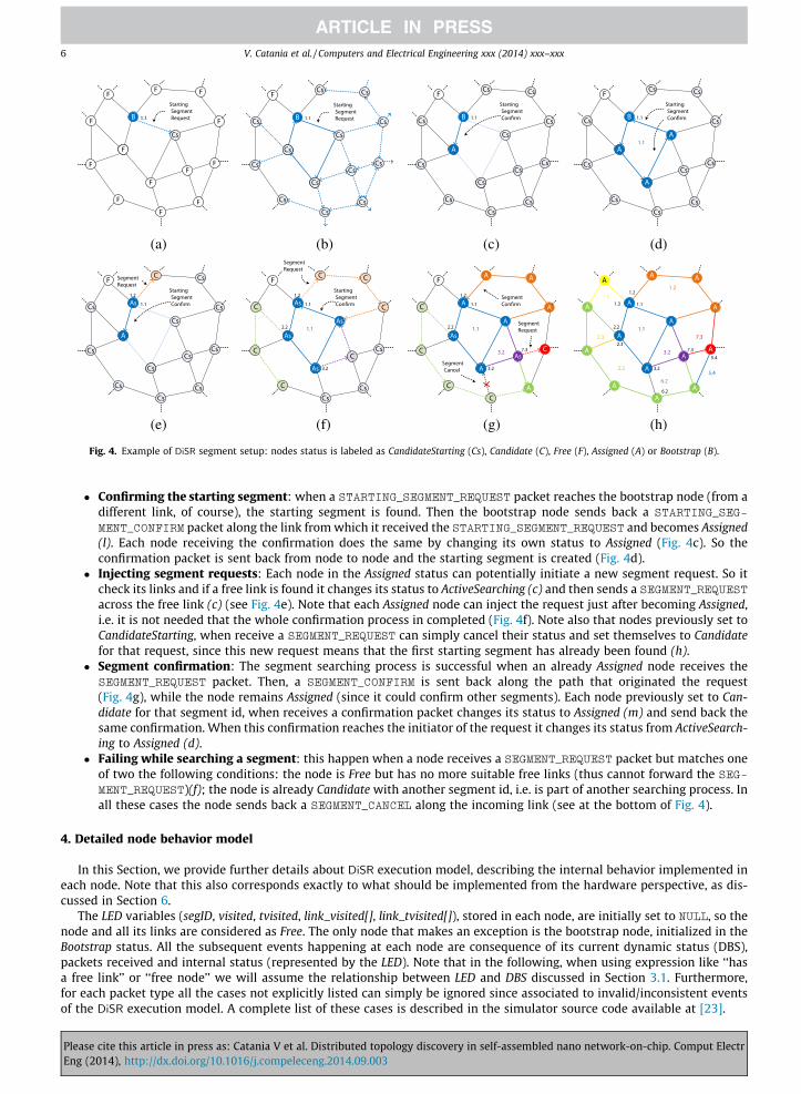
(a) (b) (c) (d)
(e) (f) (g) (h)
Fig. 4. Example of DiSR segment setup: nodes status is labeled as CandidateStarting (Cs), Candidate (C), Free (F), Assigned (A) or Bootstrap (B).
6 V. Catania et al. / Computers and Electrical Engineering xxx (2014) xxx–xxx
� Confirming the starting segment: when a STARTING_SEGMENT_REQUEST packet reaches the bootstrap node (from adifferent link, of course), the starting segment is found. Then the bootstrap node sends back a STARTING_SEG-MENT_CONFIRM packet along the link from which it received the STARTING_SEGMENT_REQUEST and becomes Assigned(l). Each node receiving the confirmation does the same by changing its own status to Assigned (Fig. 4c). So theconfirmation packet is sent back from node to node and the starting segment is created (Fig. 4d).
� Injecting segment requests: Each node in the Assigned status can potentially initiate a new segment request. So itcheck its links and if a free link is found it changes its status to ActiveSearching (c) and then sends a SEGMENT_REQUESTacross the free link (c) (see Fig. 4e). Note that each Assigned node can inject the request just after becoming Assigned,i.e. it is not needed that the whole confirmation process in completed (Fig. 4f). Note also that nodes previously set toCandidateStarting, when receive a SEGMENT_REQUEST can simply cancel their status and set themselves to Candidatefor that request, since this new request means that the first starting segment has already been found (h).
� Segment confirmation: The segment searching process is successful when an already Assigned node receives theSEGMENT_REQUEST packet. Then, a SEGMENT_CONFIRM is sent back along the path that originated the request(Fig. 4g), while the node remains Assigned (since it could confirm other segments). Each node previously set to Can-didate for that segment id, when receives a confirmation packet changes its status to Assigned (m) and send back thesame confirmation. When this confirmation reaches the initiator of the request it changes its status from ActiveSearch-ing to Assigned (d).
� Failing while searching a segment: this happen when a node receives a SEGMENT_REQUEST packet but matches oneof two the following conditions: the node is Free but has no more suitable free links (thus cannot forward the SEG-
MENT_REQUEST)(f); the node is already Candidate with another segment id, i.e. is part of another searching process. Inall these cases the node sends back a SEGMENT_CANCEL along the incoming link (see at the bottom of Fig. 4).
4. Detailed node behavior model
In this Section, we provide further details about DiSR execution model, describing the internal behavior implemented ineach node. Note that this also corresponds exactly to what should be implemented from the hardware perspective, as dis-cussed in Section 6.
The LED variables (segID, visited, tvisited, link_visited[], link_tvisited[]), stored in each node, are initially set to NULL, so thenode and all its links are considered as Free. The only node that makes an exception is the bootstrap node, initialized in theBootstrap status. All the subsequent events happening at each node are consequence of its current dynamic status (DBS),packets received and internal status (represented by the LED). Note that in the following, when using expression like ‘‘hasa free link’’ or ‘‘free node’’ we will assume the relationship between LED and DBS discussed in Section 3.1. Furthermore,for each packet type all the cases not explicitly listed can simply be ignored since associated to invalid/inconsistent eventsof the DiSR execution model. A complete list of these cases is described in the simulator source code available at [23].
Please cite this article in press as: Catania V et al. Distributed topology discovery in self-assembled nano network-on-chip. Comput ElectrEng (2014), http://dx.doi.org/10.1016/j.compeleceng.2014.09.003

V. Catania et al. / Computers and Electrical Engineering xxx (2014) xxx–xxx 7
4.1. Receiving a STARTING_SEGMENT_REQUEST
The request for the first segment should be managed differently since all nodes (except the bootstrap one) must forwardthe packet using a broadcasting mechanism. This is necessary since the request packet must return the bootstrap node.When a node receives a STARTING_SEGMENT_REQUEST, the following cases can happen:
� The node is Free: it should set itself to CandidateStarting and forward the packet along its free links, using broadcastingand marking these links as tvisited with segID found in the packet.
� The node is CandidateStarting with the same segID and src_id of the packet is equal to the node id: this means that thenode was the initiator of the request, thus a starting segment has just been found and should be confirmed sendingback a STARTING_SEGMENT_CONFIRM packet.
� The node is CandidateStarting, with the same segID of the packet but the src_id field is different from the node id: sincethe node is candidate with the same id, it means that it already accomplished the task of propagating that kind ofpackets, thus can simply ignore the event dropping the packet.
� The node is Candidate, with a different segID: this simply means that the STARTING_SEGMENT_REQUEST just received isdeprecated, because the node has already accepted a non-starting segment request originated from another Assignednode.
� The node is Assigned, with a different segID: same as the previous case.
4.2. Receiving a SEGMENT_REQUEST
When a node receives a SEGMENT_REQUEST, there are the following cases:
� The node is Assigned: a segment should be confirmed sending back a SEGMENT_CONFIRM packet.� The node is Candidate: it should discard the packet sending back a SEGMENT_CANCEL.� The node is Free and has free links: it marks itself as Candidate and forwards the SEGMENT_REQUEST to one of its free
links, according to some internal ordering.� The node is CandidateStarting: same as being Free, since a segment request circulating in the network indicates that
the starting segment process has been completed.
Note that the main difference between confirming a STARTING_SEGMENT_REQUEST and confirming a SEGMENT_REQUESTis that in the first case the node itself is included in the segment.
4.3. Receiving a SEGMENT_CONFIRM
When the node status is Candidate with a segID corresponding to the one indicated in the packet, the node set itself toAssigned to the segment segID. Further, it should forward this packet to the link where the original SEGMENT_REQUEST packetcame from, so that all candidate nodes can learn the id of the segment they belong to. Then, LED should be updated fromtvisited to visited.
4.4. Receiving a SEGMENT_CANCEL
When a node receives a SEGMENT_CANCEL packet it means that the research for a segment along that path was unsuc-cessful. If the node still has some other free link to try, it should forward a SEGMENT_REQUEST to the those links. A nodeforwards back the SEGMENT_CANCEL packet along the link that originated the SEGMENT_REQUEST packet only when thereare no more free links to try. If this is the case, the node modifies its status from Candidate to Free and forwards the SEG-
MENT_CANCEL packet to the link from which the request was received. The process stops when the SEGMENT_CANCEL packetreach the starting node that originated the request.
4.5. Intra-node vs inter-node parallelism
In the processes described above, we assumed that each node in the Assigned status can start a segment searching processby injecting a SEGMENT_REQUEST. However, different choices could have been made when defining DiSR, these choices arestrictly related to which kind and level of parallelism should be supported. The approach adopted currently is that, althoughthe nature of DiSR is intrinsically parallel, the use of parallelism should not make things work in a too complex/uncontrol-lable way. In other words, DiSR is parallel when needed, but it does not exploit parallelism as an ‘‘improving feature’’. Thus,when not needed, things should be serialized. For example: a node with free links could start several segment requests asso-ciated to the same segID, one for each free link, but serializing this operation, by investigating the free links in order, could bea simpler solution. We refer to this DiSR design choice saying that we avoid intra-node parallelism. Note that, conversely,avoiding inter-node parallelism could be more complex than allowing it: for example, we can imagine the effort generatedwhen trying to coordinate nodes so that a unique segment searching process is actually running in the whole subnet. Thus,
Please cite this article in press as: Catania V et al. Distributed topology discovery in self-assembled nano network-on-chip. Comput ElectrEng (2014), http://dx.doi.org/10.1016/j.compeleceng.2014.09.003

8 V. Catania et al. / Computers and Electrical Engineering xxx (2014) xxx–xxx
in contrast to the intra-node parallelism, the inter-node parallelism is a structural property of the DiSR algorithm and shouldnot be avoided.
5. Simulation and results
In this section we will test the proposed DiSR approach to demonstrate its effectiveness and compare it against a topologyagnostic approach based on spanning trees and broadcasting [16], to measure how DiSR performs in covering the networkstructure. Note that a direct comparison against the SR segment-based approach is not addressed here since, how describedin Section 1, our scenario assumes the non-feasibility of a centralized approach. However, all the properties of the centralizedapproach should be considered as preserved for all the nodes reached by the distributed segment coverage of DiSR. The mainpoints that remain to be addressed are:
� how DiSR compares against the state-of-art tree based approach applied to an equivalent scenario,� how DiSR scales with large networks,� the feasibility of actual implementation of the required hardware on the limited node size assumed.
5.1. Nanoxim environment
In order to quantitatively and qualitatively evaluate the proposed approach a specific simulation environment has beendeveloped, resulting in the open-source and freely available project called Nanoxim [23]. Nanoxim is a SystemC tool basedon an almost rewritten version of the Noxim Network-on-Chip simulator [24]. While some complex features have beenremoved (e.g. wormhole, congestion/topology aware routing and selection strategies) new features specifically tailoredfor the nanoscale scenario were introduced, e.g. the ability to simulate a random network, the implementation of DiSR toobtain the segment topology and the support for defective links and nodes.
5.2. Experimental setup
The following parameters have been taken into account while performing the DiSR simulation:
� Size of the network: number of nodes, on a range from 10 � 10 to 100 � 100 sized networks.� % defective nodes: the probability that a node is not working, thus having all its links not able to be utilized during DiSR
setup.� Bootstrap node: the node, from upper layer, that injects the DiSR process. When not explicitly investigating the impact
of each single bootstrap choice, a set representative regions have been considered, e.g. the central part of the networkand the corners.
To present the results, the following evaluation metrics have been adopted:
� Node coverage: this is the fraction of nodes that are assigned to a segment. In the ideal case, all the non defective nodesshould be assigned, so this metric is useful to show how some disconnected regions can negatively impact on thewhole DiSR effectiveness.
� Latency: this measures how the cycles required to complete the segment assignment scale for increasing networksizes and defect rates.
� Bootstrap node effect: this evaluates the impact of the chosen bootstrap node on the node coverage.
Since the distribution of defects and thus the resulting topology is randomly generated, a set of simulations with differentseeds has been run for each system configuration. We found that 20 repetitions are required in order to obtain statisticallysignificant results.
5.3. Results
In this section we analyze the results in terms of node coverage and latency with different network sizes, defect rates andbootstrap injection points. In particular Fig. 5 shows node coverage for DiSR and Reverse Path Forwarding (RPF) tree basedapproach (as adapted in [25]) respectively. While the first aim of DiSR is not to reach the optimal coverage, we still canobserve quite good performances as compared to the tree based approach. For low defect rates, i.e. below 10%, bothapproaches reach near ideal coverage for each of the tested network sizes. Higher defect rates seems to show more variancefor DiSR. For example, at the high 20% rate DiSR ranges from 60% to 75% while RPF remains stable at 75%. However, we canconsider this coverage sensibility at higher defect rates as still acceptable for this first, not yet optimized version of the pro-posed approach. Note that defect rates beyond 25% lead to many disconnected regions of nodes that DiSR currently cannothandle. This threshold can be intuitively related to the fact that, in the topologies simulated, a node has (on average) a
Please cite this article in press as: Catania V et al. Distributed topology discovery in self-assembled nano network-on-chip. Comput ElectrEng (2014), http://dx.doi.org/10.1016/j.compeleceng.2014.09.003

0 0.05 0.1 0.15 0.2 0.25 0.3 0.35 0.4 0.45 0.50
0.1
0.2
0.3
0.4
0.5
0.6
0.7
0.8
0.9
1DiSR Coverage
Node Defect Rate
Ideal10x1030x3050x50100x100
0 0.05 0.1 0.15 0.2 0.25 0.3 0.35 0.4 0.45 0.50
0.1
0.2
0.3
0.4
0.5
0.6
0.7
0.8
0.9
1
Node Defect Rate
Nod
e C
over
age
Nod
e C
over
age
Ideal10x1030x3050x50100x100
(a) (b)
Fig. 5. DiSR (a) and RPF (b) node coverage.
V. Catania et al. / Computers and Electrical Engineering xxx (2014) xxx–xxx 9
cardinality of 4 connections to other nodes. This means that with a defect rate bigger than 25% a node has at least one of itsfour paths as not-working, and this applies (on average) for each node, leading to higher probability of consecutive discon-nected nodes, which eventually create disconnected regions. For example Fig. 6 shows a 30 � 30 network with a 25% defectrate in which the bottom-left part cannot be reached due to disconnected regions. Note that the remaining defective nodesbelonging to connected regions are successfully surrounded by DiSR coverage; in any case, these defect levels should be con-sidered as worst case scenarios, so the achieved coverage of 0.5 is a satisfying result for this first version of DiSR. On the otherhand, the network size seems to have a limited impact when defect rate does not introduce too many disconnected regions.
The number of cycles required to complete segment mapping process is shown in Fig. 7. In this case the comparisonagainst the tree-based approach shows better (lower) values at different defect rates. Rather than the absolute numbers,what is more interesting to observe is how DiSR latency scales with network size. For example, moving from 900 to 2500nodes, at an average defect rate of 0.15, leads to an increase of latency from 3000 to 4500 cycles. It should be noticed alsohow for DiSR latency is increasing until the threshold of 0.25 is reached, meaning that the completion of the process is moreand more difficult due to the missing paths, but DiSR is still able to finish the segment discovery using the retry/cancel mech-anisms described in the previous section. This initial behavior is not reported in the RPF based approach, which does not usethe same retry/cancel approach as DiSR and then suffers higher latency values.
After the 0.25 threshold, the impact of disconnected regions becomes predominant and both approaches become faster incompleting the covering process, since far less nodes can be actually reached.
Finally, Fig. 8 visually represents the stability of the approach against a different bootstrap node choice in a 10 � 10 net-work. This is an important aspect to evaluate considering that one of the main advantages of DiSR against all the tree-basedapproaches is the possibility of choosing whatever bootstrap node, without having to care about the role assumed in thefuture by the chosen root node. In other words, after that the segments have been established, the bootstrap node is likeevery other node, i.e. it is not center of a structure, and it is not an hotspot for the traffic distribution. The results in termsof coverage, shown for low, medium and high defect profiles, demonstrate a relatively limited impact of the bootstrap nodechoice in the low/medium scenarios, while a 30% instability is found for very high defect rates. This also sounds acceptable,since when a lot of defective nodes are present, the particular position of the bootstrap node could lead to a completely dif-ferent evolution in the DiSR setup process.
5.4. Other optimizations
Some optimization parameters, which demonstrated to improve the DiSR results, have been fixed to some reasonabledefault values (see below) and are not subject to further investigations in this paper; once again the focus here is not theoptimal setup of segments, but just demonstrating a working approach. These parameters are:
� cycle_links: max number of retries across the set of links of each node. While searching for a free link due to an incom-ing SEGMENT_REQUEST, the request itself is canceled after a given number of tries. This gives to the preceding node onthe path the chance to test a different route instead of waiting indefinitely. Default value is set to 1, i.e. each link istried one time.
� time to live (TTL): when a segment request is canceled along a certain path (using a SEGMENT_CANCEL), a TTL field isdecreased in the request packet, so that requests that have been denied too much times are canceled, even if free linksare available. This is not only an optimization to shorten requests’ processes, but also solves some critical situations inwhich request packets are blocked in routing loops in a particular path.
� bootstrap_timeout: number of time units that a bootstrap node should wait before assuming that a livelock in thestarting segment process has occurred. In the worst case, we can imagine that the longest path required is the onereturning to bootstrap node after having traveled across all the links. So, although this is just an extreme situation,a good upper limit can be safely be set to N � N.
Please cite this article in press as: Catania V et al. Distributed topology discovery in self-assembled nano network-on-chip. Comput ElectrEng (2014), http://dx.doi.org/10.1016/j.compeleceng.2014.09.003

Fig. 6. Covered regions in a 30 � 30 network with 25% of defects.
0 0.05 0.1 0.15 0.2 0.25 0.3 0.35 0.4 0.45 0.5
2000
4000
6000
8000
10000
12000
14000
16000
18000
Node Defect Rate
Late
ncy
10x1030x3050x50100x100
0 0.05 0.1 0.15 0.2 0.25 0.3 0.35 0.4 0.45 0.50
2000
4000
6000
8000
10000
12000
14000
16000
18000
Node Defect Rate
Late
ncy
10x1030x3050x50100x100
(a) (b)
Fig. 7. Latency of DiSR (a) vs tree based RPF (b).
10 V. Catania et al. / Computers and Electrical Engineering xxx (2014) xxx–xxx
Please cite this article in press as: Catania V et al. Distributed topology discovery in self-assembled nano network-on-chip. Comput ElectrEng (2014), http://dx.doi.org/10.1016/j.compeleceng.2014.09.003

0 10 20 30 40 50 60 70 80 90 1000
0.1
0.2
0.3
0.4
0.5
0.6
0.7
0.8
0.9
1
Bootstrap Node
node
cov
erag
e
00.050.150.30
Fig. 8. Effect of bootstrap node.
V. Catania et al. / Computers and Electrical Engineering xxx (2014) xxx–xxx 11
� bootstrap_immunity: in order to avoid the failure of the whole DiSR setup process, a bootstrap node should not havedefective links. Enabling this optimization, a bootstrap node is immune to defects. We may think about a pre-boot-strap phase that properly selects (from upper layer via) a bootstrap node which is tested as properly connected. Weenabled this optimization, however empirical tests have shown us that only simulations using bootstrap nodes placedon edges would be heavily affected by similar issues since these nodes start with a lower number of links, e.g. cornernodes could only have two connected directions, so even a single defective link could prevent a STARTING_SEGMENTpacket from coming back to the bootstrap node to close the loop and create the first segment.
6. Hardware implementation
A possible hardware implementation of DiSR algorithm will be described in this section. Fig. 9 depicts the general struc-ture of a node in the particular scenario of DNA nano Network-On-Chip. In particular, such a node is composed of the fol-lowing fundamental elements:
� I/O buffers-transceivers: These elements, one for each port, are responsible for data transmission with neighborsnodes. The packets received or sent are stored in specific buffers named input and output buffers respectively.
� Switch matrix: Driven by a switch controller, it enables reciprocal connections among devices inside the node. Beforesegments’ creation, this controller receives information from DiSR block. After this phase, the switch controller will bedriven by the block implementing the routing algorithm. The Switch Matrix is essentially composed of a series of mul-tiplexers and demultiplexers.
Fig. 9. A possible node structure tailored for a DNA nano network-on-chip.
Please cite this article in press as: Catania V et al. Distributed topology discovery in self-assembled nano network-on-chip. Comput ElectrEng (2014), http://dx.doi.org/10.1016/j.compeleceng.2014.09.003
12 V. Catania et al. / Computers and Electrical Engineering xxx (2014) xxx–xxx
� Processing Element (PE): It is strictly related to the functionality and role that the node cover inside a given network(e.g. being a computation or storage node).
� DiSR-routing: The DiSR block contains all the hardware, control logic and configuration registers, needed by the imple-mentation of the proposed approach. The routing algorithm receives information from DiSR which indicates the statusof segments related to a particular node. Routing operations will take into account these information to obtain deadlockfreedom. Both Routing and DiSR are connected to the Switch Matrix in order to receive packets from the input buffer.Since the packets are processed one at a time, a specific arbiter should be present within the Switch Matrix controller.
6.1. DiSR architecture
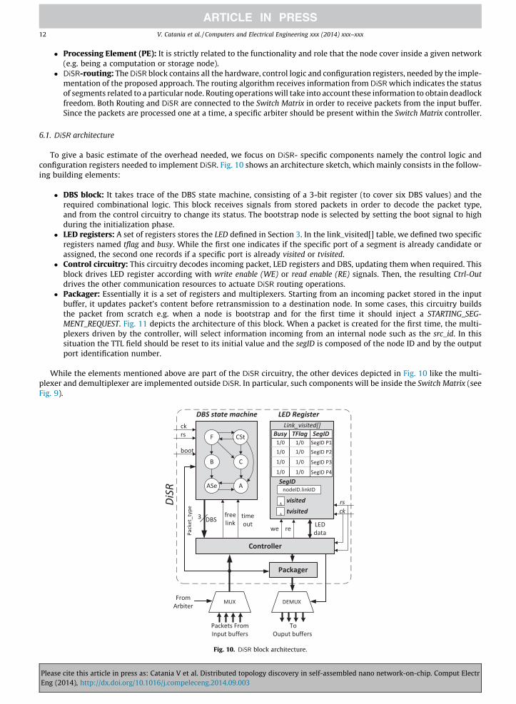
To give a basic estimate of the overhead needed, we focus on DiSR- specific components namely the control logic andconfiguration registers needed to implement DiSR. Fig. 10 shows an architecture sketch, which mainly consists in the follow-ing building elements:
� DBS block: It takes trace of the DBS state machine, consisting of a 3-bit register (to cover six DBS values) and therequired combinational logic. This block receives signals from stored packets in order to decode the packet type,and from the control circuitry to change its status. The bootstrap node is selected by setting the boot signal to highduring the initialization phase.
� LED registers: A set of registers stores the LED defined in Section 3. In the link_visited[] table, we defined two specificregisters named tflag and busy. While the first one indicates if the specific port of a segment is already candidate orassigned, the second one records if a specific port is already visited or tvisited.
� Control circuitry: This circuitry decodes incoming packet, LED registers and DBS, updating them when required. Thisblock drives LED register according with write enable (WE) or read enable (RE) signals. Then, the resulting Ctrl-Outdrives the other communication resources to actuate DiSR routing operations.
� Packager: Essentially it is a set of registers and multiplexers. Starting from an incoming packet stored in the inputbuffer, it updates packet’s content before retransmission to a destination node. In some cases, this circuitry buildsthe packet from scratch e.g. when a node is bootstrap and for the first time it should inject a STARTING_SEG-MENT_REQUEST. Fig. 11 depicts the architecture of this block. When a packet is created for the first time, the multi-plexers driven by the controller, will select information incoming from an internal node such as the src_id. In thissituation the TTL field should be reset to its initial value and the segID is composed of the node ID and by the outputport identification number.
While the elements mentioned above are part of the DiSR circuitry, the other devices depicted in Fig. 10 like the multi-plexer and demultiplexer are implemented outside DiSR. In particular, such components will be inside the Switch Matrix (seeFig. 9).
Fig. 10. DiSR block architecture.
Please cite this article in press as: Catania V et al. Distributed topology discovery in self-assembled nano network-on-chip. Comput ElectrEng (2014), http://dx.doi.org/10.1016/j.compeleceng.2014.09.003

V. Catania et al. / Computers and Electrical Engineering xxx (2014) xxx–xxx 13
All the blocks described above, react with the rising edge of the clock signal. An asynchronous system reset signal is alsopresent to restore all registers to their default values. When this signal is set, DBS state machines for each network node areset as Free. Fig. 12 shows the pipeline structure of the DiSR architecture. Packets incoming from neighbor nodes (or generatedlocally) are sent to the DBS state machine in order to ensure the status commutation. While DBS updates its state, in the nextclock cycle the control circuitry will update LED registers status and will drive the Switch Matrix in order to send the packetsto the right output buffer.
6.2. Synthesis results: timing, area and power consumption considerations
As discussed above, one of the main design challenges of DNA Self-Assembled systems is the limited number of resourcesavailable to implement both computations and routing decisions for each node. Assuming a budget of 104 CNFETs for eachnetwork’s node [11] we estimated the resources required to implement the entire DiSR block. The RTL description of the cir-cuitry described in the last section (with an hardware description language) has been written and synthesized at gate-levelusing Synopsys Design Compiler with a generic technology library (GTECH). Considering the specific layout of each single logicelement (NAND, full-adder, latch etc.), it has been possible to get a rough estimation of the number of transistors necessaryto implement DiSR logic. Fig. 13 shows the results of synthesis in terms of number of devices (CNFETs) versus the number ofnetwork nodes while the network scales up from 10� 10 to 100� 100 nodes.
In particular, Fig. 13 shows that the proposed implementation occupies about 17.5% of the node budget. The main con-tribution is due to the controller circuitry followed by LED registers. Further, more than the absolute number of devices itself,it is interesting to observe that the complexity of the circuitry necessary to implement DiSR increases with a slowlygrowing trend. This is due to the relatively simple logic of DiSR which is almost coded with scalable storage structures.For example, the number of registers implementing the link_visited[] and link_tvisited[] table follow the logarithmic functionNreg ¼ Nport � log2ðNÞ where Nport is the number of the routers ports and N is the number of networks nodes.
In order to have an idea of the maximum working clock frequency for the implemented circuitry, timing results can beobtained from a gate-level netlist. Since a complete technology library useful for commercial synthesis tool (e.g. Design Com-piler) is not available for this particular technology, we have synthesized the RTL description of DiSR, with a standard 32 nmCMOS library, obtaining a delay of about sDiSR ¼ 10 FO4 (fan-out of four). Considering the results obtained in [26], whichreports the ratio in terms of FO4 between a standard 32 nm CMOS technology and a carbon nanotube one, a rough delayestimation can be calculated. In particular in such work has been reported a ratio of:
PleaseEng (2
FO4CMOS
FO4CNFET¼ 2 ð1Þ
Considering that FO4 CMOS is about 30 ps, and the results of last equation, a FO4 for the CNFET case is equal to about 15 ps,the working frequency can be computed as:
fclk ¼1
Tmax¼ 1
sDiSR � FO4CNFET¼ 1
10 � 15 � 10�12 ¼ 6:6 GHz ð2Þ
where sDiSR is expressed in terms of FO4.With regard to the power consumption of the whole set of DiSR devices: due to the fact that DiSR circuitry will be active
only once during system startup, an accurate power analysis related to switching activity is not provided in this work. Afterthe setup phase, when all segments are mapped, the DiSR block will stop its activity passing all the information related tosegments to the routing algorithm. For this reason the dynamic power falls to zero and the only consumption is due to leak-age effects. A comparison between the proposed circuitry and the state of the art implementation for the RPF algorithm, pre-sented in [25], can show that there is not an appreciable discrepancy in terms of transistors cost and power consumption. Infacts, RPF requires an overhead of about 1692 CNFET for a 100� 100 network. Furthermore, regarding the power consump-tion, also the RPF approach has a setup phase beyond which, the consumption tends to zero.
Fig. 11. Packager block.
cite this article in press as: Catania V et al. Distributed topology discovery in self-assembled nano network-on-chip. Comput Electr014), http://dx.doi.org/10.1016/j.compeleceng.2014.09.003
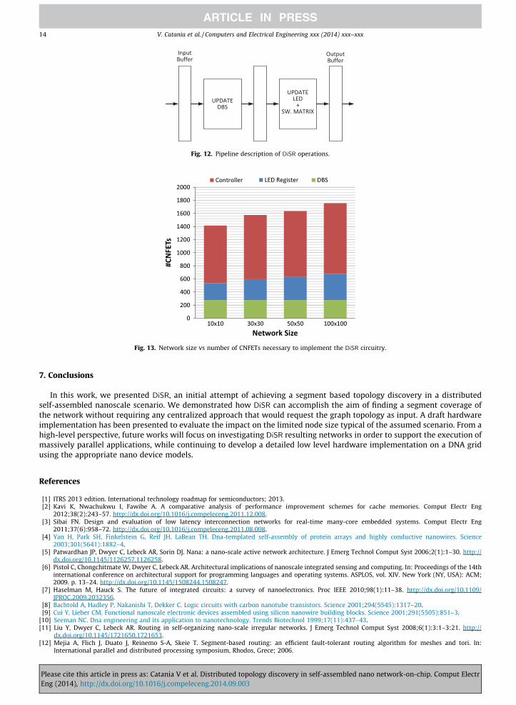
Fig. 12. Pipeline description of DiSR operations.
Fig. 13. Network size vs number of CNFETs necessary to implement the DiSR circuitry.
14 V. Catania et al. / Computers and Electrical Engineering xxx (2014) xxx–xxx
7. Conclusions
In this work, we presented DiSR, an initial attempt of achieving a segment based topology discovery in a distributedself-assembled nanoscale scenario. We demonstrated how DiSR can accomplish the aim of finding a segment coverage ofthe network without requiring any centralized approach that would request the graph topology as input. A draft hardwareimplementation has been presented to evaluate the impact on the limited node size typical of the assumed scenario. From ahigh-level perspective, future works will focus on investigating DiSR resulting networks in order to support the execution ofmassively parallel applications, while continuing to develop a detailed low level hardware implementation on a DNA gridusing the appropriate nano device models.
References
[1] ITRS 2013 edition. International technology roadmap for semiconductors; 2013.[2] Kavi K, Nwachukwu I, Fawibe A. A comparative analysis of performance improvement schemes for cache memories. Comput Electr Eng
2012;38(2):243–57. http://dx.doi.org/10.1016/j.compeleceng.2011.12.008.[3] Sibai FN. Design and evaluation of low latency interconnection networks for real-time many-core embedded systems. Comput Electr Eng
2011;37(6):958–72. http://dx.doi.org/10.1016/j.compeleceng.2011.08.008.[4] Yan H, Park SH, Finkelstein G, Reif JH, LaBean TH. Dna-templated self-assembly of protein arrays and highly conductive nanowires. Science
2003;301(5641):1882–4.[5] Patwardhan JP, Dwyer C, Lebeck AR, Sorin DJ. Nana: a nano-scale active network architecture. J Emerg Technol Comput Syst 2006;2(1):1–30. http://
dx.doi.org/10.1145/1126257.1126258.[6] Pistol C, Chongchitmate W, Dwyer C, Lebeck AR. Architectural implications of nanoscale integrated sensing and computing. In: Proceedings of the 14th
international conference on architectural support for programming languages and operating systems. ASPLOS, vol. XIV. New York (NY, USA): ACM;2009. p. 13–24. http://dx.doi.org/10.1145/1508244.1508247.
[7] Haselman M, Hauck S. The future of integrated circuits: a survey of nanoelectronics. Proc IEEE 2010;98(1):11–38. http://dx.doi.org/10.1109/JPROC.2009.2032356.
[8] Bachtold A, Hadley P, Nakanishi T, Dekker C. Logic circuits with carbon nanotube transistors. Science 2001;294(5545):1317–20.[9] Cui Y, Lieber CM. Functional nanoscale electronic devices assembled using silicon nanowire building blocks. Science 2001;291(5505):851–3.
[10] Seeman NC. Dna engineering and its application to nanotechnology. Trends Biotechnol 1999;17(11):437–43.[11] Liu Y, Dwyer C, Lebeck AR. Routing in self-organizing nano-scale irregular networks. J Emerg Technol Comput Syst 2008;6(1):3:1–3:21. http://
dx.doi.org/10.1145/1721650.1721653.[12] Mejia A, Flich J, Duato J, Reinemo S-A, Skeie T. Segment-based routing: an efficient fault-tolerant routing algorithm for meshes and tori. In:
International parallel and distributed processing symposium, Rhodos, Grece; 2006.
Please cite this article in press as: Catania V et al. Distributed topology discovery in self-assembled nano network-on-chip. Comput ElectrEng (2014), http://dx.doi.org/10.1016/j.compeleceng.2014.09.003

V. Catania et al. / Computers and Electrical Engineering xxx (2014) xxx–xxx 15
[13] Abbas A, Ali M, Fayyaz A, Ghosh A, Kalra A, Khan SU, et al. A survey on energy-efficient methodologies and architectures of network-on-chip. ComputElectr Eng 2014(0). http://dx.doi.org/10.1016/j.compeleceng.2014.07.012.
[14] Skeie T, Lysne O, Flich J, Lopez P, Robles A, Duato J. Lash-tor: a generic transition-oriented routing algorithm. In: Proceedings of the tenth internationalconference on parallel and distributed systems, 2004 (ICPADS 2004). IEEE; 2004. p. 595–604.
[15] Koibuchi M, Jouraku A, Watanabe K, Amano H. Descending layers routing: a deadlock-free deterministic routing using virtual channels in system areanetworks with irregular topologies. In: Proceedings of the international conference on parallel processing, 2003. IEEE; 2003. p. 527–36.
[16] Patwardhan JP, Dwyer C, Lebeck AR, Sorin DJ. Evaluating the connectivity of self-assembled networks of nano-scale processing elements. In: IEEEinternational workshop on design and test of defect-tolerant nanoscale architectures (NANOARCH 05); 2005.
[17] Sancho JC, Robles A, Duato J. A flexible routing scheme for networks of workstations. In: High performance computing. Springer; 2000. p. 260–7.[18] Gomez ME, Duato J, Flich J, Lopez P, Robles A, Nordbotten NA, et al. An efficient fault-tolerant routing methodology for meshes and tori. Comput
Architect Lett 2004;3(1). 3-3.[19] Koibuchi M, Matsutani H, Amano H, Pinkston TM. A lightweight fault-tolerant mechanism for network-on-chip. In: Proceedings of the second ACM/
IEEE international symposium on networks-on-chip. IEEE Computer Society; 2008. p. 13–22.[20] Flich J, Duato J. Logic-based distributed routing for nocs. Comput Architect Lett 2008;7(1):13–6.[21] Liu C, Zhang L, Han Y, Li X. A resilient on-chip router design through data path salvaging. In: Proceedings of the 16th Asia and South Pacific design
automation conference. IEEE Press; 2011. p. 437–42.[22] Ebrahimi M, Daneshtalab M, Plosila J, Tenhunen H. Minimal-path fault-tolerant approach using connection-retaining structure in networks-on-chip.
In: 2013 Seventh IEEE/ACM international symposium on networks on chip (NoCS); 2013. p. 1–8. http://dx.doi.org/10.1109/NoCS.2013.6558401.[23] Patti D. Nanoxim: nano network-on-chip simulator. <http://https://code.google.com/p/nanoxim/>.[24] Fazzino F, Palesi M, Patti D. Noxim: network-on-chip simulator. <http://noxim.sourceforge.net>.[25] Jaidev Patwardhan P, Chris D, Alvin RL. Design and evaluation of fail-stop self-assembled nanoscale processing elements. In: IEEE international
workshop on design and test of defect-tolerant nanoscale architectures (NANOARCH06); 2006.[26] Deng J, Patil N, Ryu K, Badmaev A, Zhou C, Mitra S, Wong HSP. Carbon nanotube transistor circuits: circuit-level performance benchmarking and
design options for living with imperfections. In: Solid-state circuits conference, 2007 (ISSCC 2007). Digest of technical papers. IEEE International; 2007.p. 70–588.
Vincenzo Catania received the Laurea degree in Electrical Engineering from the University of Catania, Italy, in 1982. Until 1984, he was responsible fortesting microprocessor system at STMicroelectronics, Catania. He is a full professor of computer science. His research interests include performance andreliability assessment in parallel and distributed system, VLSI design, low power design, and fuzzy logic.
Andrea Mineo received the BSc and MSc degrees in Electronic Engineering from the University of Catania, Italy, in 2010 and 2013, respectively, and iscurrently pursuing the PhD degree in Systems, Energy, Computer and Telecommunications Engineering at the University of Catania. His current researchinterests are VLSI systems, Network-on-Chip architectures and emerging interconnect technologies for on-chip networks.
Salvatore Monteleone is a post-doctoral research assistant at the Department of Electrical, Electronic and Computer Engineering, University of Catania,Italy. He obtained the BSc (2007) and MSc (2010) in Computer Engineering at University of Catania where he also completed the PhD course in Com-munications and Computer Engineering (2014). His interests comprehend cooperative systems, user-centric systems and Network-on-Chip architectures.
Davide Patti received the Laurea and PhD degrees in computer engineering from the University of Catania, Italy, in 2003 and 2007, respectively. Hisresearch focuses on Design Space exploration of VLIW systems, Network-on-Chip architectures, DNA self-assembled networks and Human-computerinterfaces. He is currently a research assistant at University of Catania.
Please cite this article in press as: Catania V et al. Distributed topology discovery in self-assembled nano network-on-chip. Comput ElectrEng (2014), http://dx.doi.org/10.1016/j.compeleceng.2014.09.003


![Report on Nano-Electronics, -Photonics, and –Magnetics ...blair/T/ece7960/papers/blair04nemp.pdf · crystalline substrate such as InAs/GaAs, Ge/Si, etc. [1,2] dubbed self-assembled](https://img.dokumen.tips/doc/110x75/606f548c1023fe3e71654647/report-on-nano-electronics-photonics-and-amagnetics-blairtece7960papers.jpg)