Embed Size (px)
Citation preview

A--7- x 0\-
DYNAMIC COMPATIBILITY OF ROTARY-WING
AIRCRAFT PROPULSION COMPONENTS
John M. Vance
Army Air Mobility Research and DevelopmentLaboratoryFort Eustis, Virginia
January 1973
DISTRIBUTED BY:
National Technical Information ServiceU. S. DEPARTMENT OF COMMERCE5235 Port Royal Road, Springfield Va. 22151

.- wZ _0 -S .- - ---
USAAMRDL TECHNICAL REPORT 73-10
DYNAMIC-COMPATIBILITY OF -ROTARY-WING AIRCRAFT
PROPULSION COMPONENTS
BYIohn V. Vance
lani 1813 -
EUJSTIS DI-RECTORATE-U. S. ARMY AIR -MOBILITY RESEARCH AND -DEVELOPMENT -LABORATORY
FORT EUSTIS, VIRGINIAR.ptcluced byNATIONAL TECHNICALINFORMATION SERVICE
U S Dr-ani ofComn-.,t.SP1.feld VA 22151
Approved for public release;distribution unlimited.

DIS-CLAIMERS
The finding? in this report are not to be construed as an official Department ofthe Army position unless so designated by other authorized documents.
--When Government drawings, specificat.ons, or other data are used for aihy purposeother than in connection with a definitely related Goveirment procurementoperation, the United States Government thereby incurs no responsibility nor anyobligation whatsoever; and the fact that the Government may have form]atred,furnished, or in any way supplied the said drawings, specificationsi or other data. not to regarded by implication or otherwise as in any manner licensing the holderor any other Ferson or corporation, or conveying any -rights or permission, to manu-facture, use, or sell any patented invention that may in any way be relted thereto.
Trade names cited in this report do not constitute an official endorsement orapproval of the use of such commercial hardware or software. -
DISPOSITION INSTRUCTIONS
Destroy this iwport when no longer needed. Do -nOt return it to the origirator.
N

r-I
Task IG162207AA7104House Task 71-26
USAAMRDL Technical -Report 73-10January 1973
DYNAMIC-%COMPATIBILITY1, OF ROTAWY -WING AIRCRAFTPROPULSION COMPONENTS
By
John- M. Vance
EUSTIS DIRECTORATEU. S. ARMY AIR MOBILITY RESEARCH AND DEVELOPMENT LABORATORY
FORT EUSTIS, VIRGINIA
Appved forpublic rease;]ditiio~nuimitedJ

UnclassifiedI Security Clastifletion
DOCUMENT CONTROL DATA. R DIse..ity classification at tite. body of abs tat a~ nd rirwi ennoDtion !"Ust be e.,t*#*d when 000 o.eeet reort 1e cieegofio4i
.ORIGINATING ACTIVITY (Cole~pfoo.U01,) 3,11.19POwR .gCUrnIVv C6ASW#PICAYION
U..Army Air Miobility Research and Development Laboratory W~ GROUPFotEustis._Virginia_______________
DYNAC COMPATIBILITY OF ROTARY-WING AIRCRAFT PROPULSION COMPONENTS
4. OCSCKIP IVS it FoI fCS(?~o of"P.ts"eJNiUve ratiiaj
6AV ,eOmitre# h~ni~, awot mila, last "ostr)
Iohn M. Vance
a.0PORTt'r 78 T& OTAL MO. OFP AOt rb ROareNP
January 1973 _________020
Cohil :T oft GRANT NC b.ORnSINCYOWS ACIPORT NuveRtiS
6.P~jC me. USAAMRDL Techinical ReporL 71-16
Task IG162207AA7 104 b~OhRNONLt(eS01 bn9G ayb
-tHouseTask_-11-6 ___________________
10. OLSI1U*4;IION STIT~t~ky
Approved fo.- public release: distribution unlimited.
11 UPPFL9SN'ARY "OTCJ 12 SPONSORING MALI ?ARV ACflIITV
Eustis Directorate
U.S. Army Air Mobility R&D Laboratory
-Astudy of problems related to vibration and dynamicm loads in helicoptcr propulsion systemis has:Z been made, it hik'-bcen- found that engine vibration, shaft whirling, and dynamic instabilities
seriously limit helicopter performance and reliability.
it is recommended that stuidies be made to justify an intelligent standardization of engine vibu-tionlimit specificaxions for helicopters, that impedancv-mobility methods be developed for optimizingcnginelairframe interface design. that research and development of helicopter power transmissionshafts and couplings be carried out to solve whirling problems, and that new methods and hardware
f be developed to eliminate torsional instabilities in helicopter drive systems with automaic fuelcontrol.
L"~v a.iarsotOW4,11K14Jm '"t
DDI"*V01 7 00 "' n~fe

Unclassified
.x OO INK( A j LINK S LINK C-
ROLVW ? mOLt wf *0C
VibrationHelicoptersTurboshaft EnginesDrive Shaft Dynamics
Torsional Stability
Ij.
sef Classificato

AStI'RACT
A -study of problems related to vibraton and dynamic loads in helicopter propulsionsystems h.s been made. I. las beeni found that engine -ibration, shaft whirling, anddynamic instabilities seriously limit helMopter peformance and reliability.
it is recommended that studies be made to justify an intelligent standardization ofengine vibharion hmit specAlcaions for helicopters, that impedance-mobility methods bedeveloped for optimizing engine/airframe interface design, that research and develop-ment of helicopter power transmission shafts and couplings be carried out to solvewhirling problem, and t.at new methods and hardware be developed to eliminate tor-sional instabilities in,-helicopter drive systems with automatic fuel control.
~iii
Preceding page blank

r7
FOREWORD
In. this report, -.he dynamic conipatibilivy of helicopter propulsion components is con-sidered from the sta.:dpoint -of assessing what can be done in this area ~o improvehelicopter reliability and performance.
The subject is divided into fou. major subareas: (1) engine vibration limits, (2)engine/airframne iAtory interface design, (3) drive tr~in dynamics, and (4) torsional
- -- stability. A section on each srharea briefly describes the state of the art, states themajor problems encounte , provides sicne motivation for the re-ommendations to bemade, and recornmencs research and development in specific directions.
- The importance of the i ferences listed at the end of the report should not beunderestimated. It is st ~tl ug dta noe int-nding to pursue the recoir-
mendations contained in 'ris report should became- familiar with these references.They in turn will suggest further study.
Addi tiona background m~aterial and pertinent informtion obtained from publishedreferences are given in the appendixes.
The work reporwed herein was authorized by DA Task IG162207AA7104, House Task71-26.
V
Fteceding PaIP Nank

TABLE OF CONTENTS
Paige
ABSTRACT ................................................................................ ii
FOREWORD ................................................................................. v
LIST OF ILLUSTRATIONS ................................ I............................. viii
LIST OF SYMBOLS.........................................................................x
INTRODUCTION............................................................................ 1
ENGINE VIBRATION LIMITS ............................................................ 3
ENGINE/AIRFRAME INTERFACE DESIGN............................................ 14
DRIVE TRAIN DYNAMG'S.......................... ................................... 22
TORSIONAL STABILiTY OF HELICOPTER DRIVES WITH AUTOMATICFUEL CONTROL......................................................................... 27
CONCLUSION............................................................................... 30
SUMMARY OF RECOMMENDATIONS.................................................. 31
LITERATURE CITED ...................................................................... 34
APPENDIXES
1. lIpedance- Mobility Methods for Vibai Analysis .................. 36
I. Cornputer Programs Currently in Use or Available forHelicopter Enginc/Airframe Vibration Analysis ..................... 45
DISTRIBUTION ............................................................................. 48
vii
precedine page blank
LIST OF ILLUSTRATIONS
Figure Page
1 Two Systems in Which the Ratio of Vibratory Strain to VibratoryVelocity Is and Is Not Independent of Frequency .................. 7
2 Art Engine Case/Rotor System With Disc Unbalance and Vibrating
M ount ....................................................................................................... . 8
3 Mobility Diagram for Case/Rotor Assembly With Airframe Excitation 9
4 Mobility Diagram for Case/Rotor Assembly With Unbalance Excitation 12
5 Mobility Schematic of Engine and Airframe To Be Connected byMounting Element Me Between Points ! and 2 .................................... 15
6 Equivalent System (for Me) Obtained by Application of Norton'sT heorem .................................................................................................... 15
7 Mobility Me of Soft Engine Mount ........................................................ 16
8 Internal Mobility of Engine/Airframe Assembly .................... 17
9 Blocked Force Fb in Rigid Mount ....................................................... 17
10 Mobility Schematic of Airframe With Engine and Mount To BeInstalled Between Points I and 3 ........................................................... 18
ii Equivalent System (for Me) Obtained by App cf Thdvenin'sT heorem ............................................................... ................ ............ 19
12 Mobility of Engine/Mount Assembly ....................................................... 19
13 Internal Mobility of Airframe ............................................................ 20
14 Free Velocity of M ount Point ............................................................... 20
15 Schematic of Typical Cross Shaft Assembly ........................................ 22
16 First Flexural Mode Shape for Drive Shaft ................ ... 23
17 Rigid.Body Mode Shape. Cylindrical Whirl ....................... 23
18 Rigid-Body Mode Shape, Conical Whirl .......................... 23
vii.:

M aear -ER -=
A
Figure Page
19 Mobilities of tEli Basic Elements ......................... ..... 38
20 Mobilitv Schematic for Dampcr. Spring. and Mass in Seri.es.............3
21 Mobility Schematic for Damper. Spring. and Mass in Parallel .......... 40
2 2 Simplified Model of Engine Case, Ru.tor Assembly...................... 4 11
23 Mobility Model for Response of Case to Rotor Unbalance.......4 1
24 Mobility M~ Added Between Two Points in an Existing Str'.cture 4 3
25 Th~vcnin's Equivalent Systemn................. ............................... 4
26 Norton's Equivalent System...................................................... 44

LIST OF SYMBOLS
An virrt- "h pcC 'An amh hi' n-
dampviig co-nstant, -
C cros,scucnail d~nmcnsuv; fr in nc _a xh t~~c ~bean, ;n.
D determlinant of matrix
ethe base of N a pC ic-- I'r-- m 2.53
E Y o un gs modulus. 'Iim?.
.or ce in a borce Enerator-l. lb
Fb blocke d frce. L
F, for-ce in ad-ded eir-emn.l
F; intrlnal force in Norton s equivalent systemn.l
F3.Fforce at stations i. 2. 1. and-A lb
area moment of inertia, in.4
KRB, K
m Spring concztant, lb-im.
t length.r~ of a beam. m.
Mn. m,1 l.senl-s. -
Ini.
momentE. In.-ib

; Met Mi,
MI, M2,
M2 mobility, in./ib-sec
11 an integer defining a vibratory mode
N an integer
t time. sec
VnI vibratory velocity in the nt h mode, in.
Vo free velocity, in./sec
V3 , V4 velocity of stations 1, 2, 3, and 4, in./sec
x position along a flexible member, in.
Xn vibratory displacement of a lumped mass in the nth mode, in.
Yn vibratory displacement along a flexible member, in the nth mode, in.
s lb-secZ impedance, -se-
in.
ex strain in the x direction, in./in.
lbsec2
p mass per unit length, -- T-
SOx stress in the x direction, lb/in.2
G) frequency, rad/sec
Cin frequency of the nth mode, rad/sec
SYMBOLS IN APPENDIX I
f force in basic physical elements, lb
F amplitude of f, lb
xi

lb-sec2in mass,
in.
M21 tra i-sfer mobility, in./scc-lb
v vibratory velocity of basic element, in./sc
V amplitude of v, in./sec
xii

INTRODUCTION
Vibration, shaft whirling, and dynamic instabilities have imposed major limitations onthe performance and reliability of helicopters since their inception. In addition to thelimitations that have been directly attributed to vibration, there is little doubt thatvibration contributes to proble!ms attributed to other'causes. Fo: example, turbineblade failures in helicopter engines, which are normally associated with thermal effects,might occur less frequently in a less severe dynamic environment.
Even if indirect effects are ignored, however, vibration-related failures of helicopterpropulsion components in the field make mandatory the establishment of betterdynamic compatibility of these components.
Vibratory excitation in a helicopter propulsion system can be either from mechanicalsources, such as the whirling of shafts, or from aerodynamic sources, such as theN/rev excitation at the hub of the rotary wing, generated by the air loads on the
blades as they alternately advance and recede in the direction of flight. Althoughneither of these sources of excitation can be completely eliminated, efforts can be andare being made to reduce the magnitude of both.
Mechanical excitations can be reduced by improved- balancing of rotating components,by the avoidance of near-resonant conditions, and -by the elimination of self-excitedwhirl and vibration. These techniques will be discussed further in subsequent sections.
The subject of aerodynamic excitation is so broad and complex, and is beingresearched so thoroughly by other investigators, that it will not be discussed in detailhere. Rather, it is assumed that a certain amount of aerodynamic excitation willalways be present in helicopters, and the question of optimum propulsion systemdesign to survive in this environment will be considered.
Devices to dynamically isolate the rotary-wing assembly (mast, hub, and blades) fromthe rest of the helicopter are under development. Some of these device.s are "active",requiring external energy to provide counterbalancing excitations over a wide frequencyrange; others are "passive", similar to the Frahm dynamic absorber. Reference 1summarizes the most promising concepts.
It should be recognized that the aerodynamic sources of excitation are governed to alarge extent by the basic design of the helicopter, such as the number of blades onthe rotor. If additional flight test data is obtained, it may become possible to quan-tify these effects to the extent that vibration can have proper consideration in earlydesign decisions. This report, however, is aimed at dealing directly with the currentproblems of dynamic compatibility in helicopters of contemporary design.
The adoption of turbine engines originally designed for fixed.wing applications hasemphasized the need to consider the dynamic interactions of engine, drive train
\1

(shafting, transmissions, and rotors), and helicopter airframes. In addition to beingoriginally intended for a dynamic environment less severe than that provided by thetypical- helicopter, the turboshaft engine has also required developmerst of power transmiMion systems with very high overall speed ratios and high horsepower capabilities.Since speed reduction must often be accomplihed-in s-stra stages -tha t may h&
physically remote from one another, it is difficult to pevent whirling and vibrationgenerated by the many rotational frequencies inhernt in- the shafting and gearboxes.
The advent of automatic speed governors on large -helicopters has created a specialproblem of maintaining torsional stability of the engine and drive train whqe at tiesame time providing a sufficiently rapid response to demand for power and speedchanges.
Thus the overall problem of achieving dynamic compatibility in helicopter propriisionsystems can be -conveniently divided into four major areas: (1) engine vibration limits,(2) design of tie engine/airframe-interface, (3) whirling and vibration of power trans-
mission- shafting, gearbioxes, and- bearings, and (4) torsional stability- of the engine- anddrive train with- clo sed-op fueLco-trols. These four -a'e a treated in detail ii_-the -sections- that follow, each with a -review of the -state of tihe ardt and reconintenda-tions for future -research and -develpiient.
2

II
T
forP~~oma~e~it~ ENGI VIRON LIMITS
The uffie-cts of virto ntrohf niereliability (and consequently on helicop.
ter pefrac iis r eonzdb ieengire manufacturers, recommendationsfor ngie viraton imit. -Oneof te ciefcharacteristics of thcsc limits is thate ih mnutctuerexpesss temin diferntform. Reference 2 discusses tileCesiabiity f sandrdizng he ethos o c ablishing and applying these limits.
Engine vibration firriks are usually expressed as maximum loal displacement,loctyacclertio, o bedin anleY,.susdiscrete freuecy of tile passing filter
or harmonic analysis. Sometimes limits oil overall mitus 1 summed over all
Both he loationof t e nasurciment transduce.rs and their orientation are specified
Somie of dhese iiiits were established with fixed-wing aircraft as the expected applica-tion, and there i, a question to be answered~ about their applicability to helicoptersbecause of ,lie lowoer trequencie,, and higher vibratory magnitudes encountered. Thisquestion really boils down to a more babic question:- What are the relat;-. contribu-rions to- -Lpgi ic vibration from (1) thhelicopter rotor and airframe and (2) theengine itself "such as turborotor unbalance),. in fact, there are several such questionswhich must he answered by experimental and analytical rgsearch before engine vibra-tin lirtits can be intellig'ently standardized. Some of -these questions are:
1. What is the rypIcal vibratory environment encountered by heclice-pterengines? Cart this environment be improved by airframe designerswith a reasonable amount of effort? Can it be improved by properengine rnount design? How does th -vibratory environment vary wthmission profiles? With the type- of helicopter (L., -number of blades,numher of rotors, etc.)
2. What is the best paramieter (displacement. veocity, acceleration) to usern riau ingad spccifying engine vibration? Which is the easiest to
mesre Th mos - convenient for analyis' The most directlyrelated to potertrial structural darvagc?-
3. What are -lhe best loc-tions and dir--ctional orientations for enginevibration transducrs t- measure severity of environment? To measurepratential of structural damage? To measure response of internal partsBauchas engine rotor whirl and flexurc)-f
Th-piamcr ea;siest to measure may not be best for other purposes.
3

4. What is the most itseful and realistic method of data analysis (i.e.,
discrete frequency magnitude, power spectral density. 1/3 octave?eeraging, etc.)? Is more than one method of data analysis required.n order to establish meaningful vibration limits?
Of course, all of these questions relate to the problem of c;zablishir.g engine vibrationcriteria that are both realistic and at the same time will improve helicopter reliabilityand performance.
With respect to question 1, the only way to accurately define the vibrational environ-ment in contemporary helicopters is through acquisition and analysis of flight test data.The present situation is best summarized by a quotation from Reference 1:
"... the most important finding of this study is as follows:An appallingly small amount of directly applicable experimeltaldata exists on the vibration environment in operational helicop-ters. Moreover, almost no data have been collected undercontrolled conditions in an operational setting to determine theeffects of this helicopter vibration regime on flight crew per-formance and physiology."
The same statement applies here if the last five words are changed to "engine per-formance and reliability," The key to this problem is that vibration data must beacquired at the proper locations and using the techniques which are designed for heuse to which the data are to be put. There are some data available, but they wereobtained mostly with the objective of defining aerodynamic loads and consequentlyare of little use in defining the engine en'ironment. Ideally, of course, engine dataand aerodynamic data should be obtained simultaneously so that the effect of thelatter on the former can be determined. In practice, such a test would tax instru-mentation capabilities to the limit and beyond.
It is recommended that exisr:ng flight test data be analyzed to determine:
* The spectrum of engine vibration amplitudes for typical military missions.
4 The relative contributions of engine and airframe to engine vibration.
" Amplitude versus discrete frequency ovr the range from 10 to 10,000 Hzfor flight conditions dorn.nating the mission profiles.
* Predominant responding mode shapes for the engine (both rigid body ;ndflexural- if possible).
4

I-
it is further recommended that additional flight test data be acquired from a repre-sertative group of the different types of helicopters for analysis as described above.
- On first corsiderarion of the question as to whether displacement, velocity, oracceleration is best for vibration me=nrement and specification, many vibrationengineers assert that it makes no difference since they ate directly related (for discretefrequencies) by rthi, frequencv w. Howe-,er, there are some whose experience inmeasuring e~cine vibration has led them to strong opinions in favor of one parameterever the ohers.
For ex ,mplc, White 3 suggests that the magnitude of vibratory velocity is the bestmeasure of the destructive potential of vibration. He bases this hypothesis on (1)observa-ions of the trends of test results and (2) consideration of the velocity-strain
relationship for simple mathematicil models i- which strain is proportional to curva-ture (e.g.. seams). To illustrate this concept, consider a simply supporri- Cniform
beam executing undr.mped free vibration in each of its natural modes (Figure ia).The displacement ard velocity of the nth mode are given by
nIxYi1 An cos Ont sin n~x
nixYn -A n i 't sin sin
where wn = n2w i2
Thus ihe peak velocity is
Vmax - n2 r
for the nt h mode.
The bending strain ex is given in terms of curvature by0x Mc dly
SE El dx 2
Thus for the nth mde, the strain is
exn =An I n I cos Wnt sini
n5

- - --7 -
and the maximum strain is
The ratio of maximumn vibratory velocity to maximum vibratory strain is then (for
each mode)
Vmaxex max P
which is seen to be independenc of frequency.
Vibration does not always invrive bending flexure, however. Especially at lowerfrequencies, a measured velocity may indicate rigid-body modes, in which the strainin springlike elements is proportional to displacement rather than velocity. Forexample, consider the lumped mass system of Figure 1b, in which the springs canrepresent any element which deflects in direct tension. compression, shear, or torsion.Displacement and velocity for the two modes are given by
X -- a sin cot
X2= a sin c'ol t
X2 a (i cos wi
and
X,= a sin CAY2 t
X= -a sin (W2 t=
1,= a W 2 COS (A) 2 t
R2 -a (A)2 COS (A), r
6

Mo d*
Nil XZ-~2ad _ _ _
it Mod#: X,
2.4 Modo: X, -X 2
Figure 1. Two Systems in Whi,:h the Ratio of Vibratory Strain to VibratorfVc!ocity Is (a) and Is Not (b) Independen~s of Frequency.
consider a& measurement to be made of the peak velocity of X, which is to be
Z related to the strain in the spring to the left of Xl. The stri is e= The
47-1 peak velocity in either mode Fs V = i o. The ratio of measured velocity cc peak
strain -is W-= z, which Le~ dependent on the frequency. Clearly, then, in this casevibratory velocity alone would not be a sufficieni measure of the destutv otntalof vibration.
I t is recommended that a study be made to determine the~ extent to which vibration-related engine component failures can be reliably related to vibratory vei.3chy alone.This study should consist of two phases:
1. A survay of vibratory engine failure historie-s made in conjunction withvibration surveys (flight test data analyses) of the same engine installations.
2.Analysis to relate vibratory strain in complex engire structural1 componentsto vibratory velocity measured at the locations recommendd by engine
W manufacturers.
Anothe~r reason given by White3 for preference of vibratory vele-city as a measurement- parameter is that the measured vibratory response tends to remain consraitt with
frequency. It is recommended that a study be made to ratioi'Aize thes observationson a sound theoretical basis, thus improving our understanding of engine vibratoryresponse to bioth interna! and externalJ excitation.
The question of vibration transducer- loration is treated in Article 3.17.3 of MIL-E.8593 by the statement: "The points ofaicrachment -or the vibration detecrors Shall
'Based on the maximum strain theory.
7
be shown on the engine installation drawing, and shall provide for determination ofvibration in chree mutually perpendiculair planes. In particular, Lhe vibration pickupmounting points shall be located in close proximity of at least two main bearings."
The evident attempt in this statcnient to require transducers to be located such thatbearing whirl (and thus, presumably, rotor whirl) would be detected is laudable, butit can be shown that the possibility exists for severe rotor whirl or vibration to occurwithout significant vibratory response of the external bearing housings or engine case.
Consider a simplified engine case/rotor assembly (Figure 2) in which the engine caseis representel by a beam of uniformly distributed mass and stiffness, the engine rotoris represented by a massless beam with a centrally located massive disc, and theengine mounts and rotor bearings are represented by springs. Since the system isassumed to be linear, response to external (airframe) excitation and internal (engineunbalance) excitation can be considered independently and later added together to givethe total response, if desired. The effect of damping is neglected.
Figure 2. An Engine Case/Rotor System With Disc Unbalanceand Vibrating Mount.
To demonstrate the relationship which a measured stcadystate vibratory velocity at"B" or "C" on the engine case has to the velocity of the rotor disc, the mobilitymethod of analysis will be used.
Impedance.mability methods for vibration analysis are described clearly in Reference 4.and a condensed description is given in Appendix i of this report. These methodsare especially well suited for problems enci'untercd in establishing vibratory compati-bility of helicopter propulsion components. Figure 3 shows a mobility model of thecase/rotor assem bly, with a velocity generator repres enting airframe excitation at theeulgine mounts.
8
iv

00
000 000 00 077777 7f777' 77l7TT
Figure 3. Mobility Diagram for Case/Rotor Assembly With Airframe Excitation.
The combined flexibility of the rotor and bearing supports is
_kRkB
k RB k + Irn
The mobility equations are
vt va ico.i V,% V3 iw.,
Tm- F3 RB
V'2 V4 iC~J V3 1F =C r iwa Md
V4 F2 + F3
which can be reduced by substitution to the matrix equation
(kc + k) - c&c V2 - m
k 0 M c kc) V4 0
with solution
_km (w, mdj IRB) (w, mc kIcV VB D V
9

2
-kRBkm (wi mc - kC)D
S-kck m (wil md - kRB)D
where
D = determinant of the matrix(c+ki) 2 2+ 2 2 -
=(kc + km ) (o1 md - kRB) (A)2mc- kc) + kc (W1 md kRB)
2 2+kRBW mnd (Co mc - kc)
Of special interest are the ratios of vibratory velocity at the rotor disc to vibratoryvelocity at points "B" and "C" on the engine case:
V3 Vd -kRB
V2 VB W2 md - kRB
V3 Vd kRB(co mc kc)
V4 Vc kc (o 2 md - kRB)
The conclusions that can be drawn from this model of engine respone to airframeexcitation are as follows:
1. In general, rotor disc response docs not follow the same trend as responseat engine case location "B" or "C". In particular, Vd/Vb Y- 1. Vd/Vc * 1.
- V, At other frequencies and2. When Vc = 0 at antiresonance, V d =kRmVB tohr rqece n
RBwhen the airframe excitation is fixed. ti~e best way of reducing vc to"acceptable" levels is through a reduction in mount stiffness kin, since this
also reduces the rotor response Vd
3. < -C 2 < k R B . that is, when the airframe excitation frequency
mc m d
falls between the first engine bending mode ani the first rotor mode.
10

I
Vc and Vf are 180 degrtes out of phase, a condition that maximizes the
possibi.ity for blade rub to occur. Practical values of damping will modifythis conclusion only slightly.
4. The engine case response near bearing locations (point "B") could be zerounder two conditions:
2(a) k RB = WI M d' or
2
(b) kc = WI me
-kmFor case (a). Vd = kRB
For case (b). Vd = 0
Therefore, from the standpoint of engine rotor response, a low measured level ofvibration at "B" can be more significant than a low level at "C", especially if thesystem is closer to case (b) than case (a) (which holds true, for example, in theCH-531T64-6 installations), or if the engine mounts are of low stiffness.
A similar analysis of the response to engine rotor unbalance (Figure 4) is given inAppendix 1. The results lead to the following conclusions:
1. In general, rotor disc r-!ponse does not follow the same trend as responseat engine case location "B" or "C". In particular, Vd/Vb * 1, V dV c * 1.
2. If point "B" is at antiresor.ance (VB = 0), then the rotor response toicw2 FI
unbalance, V d 2 , can be quite large (i.e., a low measured(W2 md - k RB)
level of vibration near bearing supports may not indicate a low level ofrotor response).
kc 2 kRB3. if < < . and if the engine rotor unbalance is fixed, a
reduction in mount stiffness km will lessen the rotor response to unbalance.
Of course, the mathematical models considered above are greatly oversimplified, andthe conclusions may not be applicable to some real engine installations. However.they do illus'ratc how ,neasurements of engine vibration at external locations mnay notbe representative of the vibratory response of internal engine parts (specifically rotors1 .
I1I

r_-4 V3 v= v
MC 2
O000 000 O-7777777 t777/I!1711771
Figure 4. Mobility Diagram for Case/Rotor Assembly With Unbalance Excaawn.
If engine case vibration is to be used as a measure of acceptability for enizne vibra-tory limits, it is recommended that thorough investigations be conducted to determinethe relationship of vibration at the points of measurement to response at othercritical locations.
With regard to engine rotor response, it is recommended that special attention begiven to the effect of squeeze fulm bearing dampers being used in the most recentengine designs. These dampers may render the conclusions reached from thec mathe-nmtical models considered above invalid.
If exte~rnal engine vibration measurements are to be related to engine rotor whirl andvibraion, L.:ter methods of measuring zotor whirl will have tco be- de-mloped. Tilsis especially true of flexural whirl, which cannot be measured at bearing journal lo-ca-tions. It is therefore recommended .lhat an investigation bW_ made to deter.-ine thebest methods for measur-M~g engine rotor flexure undcr operating conditions. and thatthe most promising methcds be developed to a practical stare.
The final question to be- answered before en me vibration limit- can be sz..ndardzed..,t egard to the best method for data analysis, tray have a multipl- answer. Th.
discrete frequency methoad, which is in fairly common use for expre-s'%e. engine hmnits.ire the followfing disadvantages:
• mpitds t ert fferenE frequenies may e idivdually swniz~ tbut may sum to unacceptable values, especially if one V--e*uency ,.s amult*
pie intezet of another.
" it is difficult to perform discrete frequency measurentns. They requitesophisticated equipment and extensive processig.
On the Other hand. measurement. of overall vibratory amplitu.de, summewd o-e-r A!ifrequ- ncies. may nor, be sufficient since there is no way of de-erminng me-de sh-avor the relative contributions from a,¢tfime and engine exci-ta~t:.n.
- w -12
3
This question of data analysis is closely tied in with the previous question of trans-ducer location. For example, an ambiguous aspect of some specifications presentlyfurnished by engine manufacturers is caused by all measurementb" being taken in oneplane, especially a transverse plane. This type of specification makes a measurementof both amplitude and frequency almost mandatory.
It is recommended that vibration data acquisition and analysis on future programs beconducted with sufficient detail to identify both amplitudes and modes of responseuntil enough is known about engine limits to allow a simplification of methods with-out sacrificing predictability of failures. The identification of modes will usual '
require phase data in addition to frequency data, and will also require intelligentplacement of transducers at more locations than is presently zustomary.
13

ENGINE/AIRFRAME INTERFACE DESIGN
An investigation to determine optimum engine/airframe interface characteristics of ameditim transport helicopter was supported by the Navy BuWeps as an addition to thehelcopter development program. Except for stiffness in the roll mode to resist enginetorque, the engine mounts were made "soft" in order to isolate the engine from theairframe at frequencies above about 15 cps.
Results from the mobility analyses of the simplified engine case/rotor models con-sidered in the previous section also indicate that, for several cases of interest, areduction of engine mount stiffness can reduce v'bratory response to both airframeexcitation and engine rotor unbalance.*
The impedance-mobility methods of analysis hav characteristics which make themuniquely well suited to the problem of determining optimum engine mount properties.This is especially true since the engine vibration response is to be measured only at afew select points of interest. The mobility methods to be .Jlustrated below are formedin terms of the ratios of the vibratory velocities of these points of interest to thedriving force. If the poi'-- of interest is the same point at which the driving force isapplied, the ratio is called "driving point mobility"; otherwise, the ratio is "transfermobility". The response of complex structures, or several combined structures, tosteady-state excitation can be analyzed in terms of "mobility boxes", wlich greatlysimplify the system conceptually and which eliminate the unneccssary zonsideration ofinternal parameters (i.e., parameters not associated with the points of inteest)-
Another factor which makes mobility methods especially well suited to engine/airframeinterface design analysis is the usual early availability of the designated engine inhardware form while the airframe is still on the drawing board. Since the enginemobilities can be determined by testing, a very accurate and condensed model of theengine strcture can be included in the overall dynamic model in the form of thesemobilities.
Finally. there are theorems in mobility analysis, to be illustrated below, which greatlyfacilitate determination of the effects of inserting a single connecting element into astructure, such as an eng-ne mount.-
Consider first the problem of determining the effect of replacing a very stiff enginemI ount by a softer one in an already existing engine/hirframe design. Figure 5 showsthe air.rame and engine represented schematically by mobilities M, and M2 , with
*A significant factor not considered, however, is engine-transmission shaft nmisalign-inent. which can become a serious problem when soft engine mounts are used
"Engin- mount is used in the singular sense here because the models to be used forillustration will be simple and one dimensional, requiring combination of the effectsof all mounts, say, in the vertical direction, into a single effective "mount".
14

points I and 2 to be connected rigidly. The airframe mobility M, is a driving-pointmobility looking back from engine mount point 1. The engine mobility M2 is adriving-point mobility looking into the point of attachment 2. A source of airframe
excitation is designated by Fej(Lt, representing a vector component (say, vertical) oftle sum of aerodynamic blade forces at the hub for frequency w
2 1
- 1 II ..
R*2
ENGINE AIRFRAME
Figure 5. Mobility Schematic of Engine and Air" i,ne To Be Connectedby Mounting Element Me Between Points I and 2.
Figure 6 shows an equivalent system obtained by application of Norton's theorem, 4
which can be used to determine the force and relative velocity across the soft mount.
V 2 - V
000
Figure 6. Equivalent System (for Me) Obtainedby Application of Norton's Theorem.
15
Me represents the mobility of the soft mount, Mi is the "internal mobility" of theengine/airframe system without Me, and Fb is the steady-state force that would existin a rigid link connecting points 1 and 2 (i.e.. in the rigid mount). The internalmobility Mi is simply the sum of driving point mobilities M, and M2 •
An analysis of the equivalent system yields the steady-state force Fe in the softmounts and the relative velocity between engine and airframe at the poiats of attach-ment. The force F. can then be used in conjunction with engine transfer mobilities(perhaps experimentally measured) to .2redict vibratory response at points of intereston the engine.
To illustrate this method, let the airframe and engine be simply represented by singlerigid masses m, and m2 respectively, and let the soft engine mount consist of aspring of stiffness k. From Figure 7, the engine mount mobility is given byme = iw/k (see Appendix 1I).
000 0
Figure 7. Mobility Me of Soft Engine Moun..
Frcm Figure 8, the internal mobility is
mi 2 + M I
Mi = i(mjm2 = MI + M2
From Figure 9, the "blocked force" is Fb = M -- F. An analysis of the
equivalent system shown in Figure 6 yields
VI V2 VI - V2Fb Fe + Fi Me + Mi
16

MeMi 2 m 2 FVa - V2 = Fb Me + Mi iwk o 2 mlm 2 - k(m, + m2 ))
V I - V2 - km 2 FFe = Me = Amm 2 - k(mI + m2)
0000
FF = F
Figure 8. Internal Mobility of Engine/Airframe Assembly.
2L V's,. 6
F, - v
F,6 F VI ao
Figure 9. Blocked Force Fb in Rigid Mount.
17

Then, to find V2
M 2 V2 V2I-, V2 = -kFFe iWm 2 ico[o 2 mnm 2 - k(m + m2)l
of course, for such an oversimplified model, a less complicated method of analysiswill vieid the same result. However, the example illstrates the following possibilitiesfor real systems:
1. The blocked force Fb can be directly measured in an existing helicopterwith a rigid engine mount.
2. The internal mobility Mi is made up of driving point mobilities M, and M 2,
either one of which can be either calculated using existing computer analysesor measured in a shake test.
3. For a more realistic model, the mobility %2 used in the final step would bea transfer mobility for the response of so=e particular point of interest onthe engine; this mobility could be accurately determined from engine shaketests.
similar scheme for applying Norton's theorem in terms of electrical analogies is givenin Reference 6 for a missile-payload problem.
Another theorem that can be dsed to advantage in dynamic interface problems isThdvenin's theorem.4 Figure 10 show . xframe represented by mobility MI,excitation at the rotor hub represented by a harmonic forcing function, and with anengine and mount assembly to be represented by mobility M e and instaied betweenpoints I and 3. where 3 is ground. Figure 11 shows the equivalent system obtainedby Thdvenin's theorem. M i is the driving-point mobility looking back into the air-frame from the engine mount point 1, and Vo is the free vibratory velocity of point1 without M e.
AlMe f
ENGINE & MOUNT AIRFRAME
Figure 10. Mobility Schematic of Airframe With Engine and MountTo Be Installed Between Points I and 3.
18

II
rv =0
Figur 11 ivlnrSse frMe bandb
k0 0
Asa im le trto of __ aplcain cosdrtesm sse k t r
From ~ Figure 12 M obility of ngine/mount assembly.
19 -M

From Figures 13 and 14, the internal mobility of the airframe is Mi : . ,and
the free velocity of the engine mount point is Vo = Fla0mj
V
Al0 = V = _ _ t
FFFigure 13. Internal Mobility of Airframe.
F F
F Z r4 'm
Figure 14. Free Velocity of Mount Point.
Analysis of the equivalent system shown in Figure 11 yields the force in the engineas
Fe Vo -km 2 F
Me + Mi o2M rM 2 - k (m, + M 2 )
20

Once again, the oversimplification of the system does not justify the method of analy-sts. However, for realistic models, it can be seen how the mobility method allowsexperimental measurements or computer resuits to be integrated into the analysis formaximum advantage. This might be done in the analysis just described as follows:
* The mobility Me can be deteim-ined from an engine shake test.
* The internal mobility Mi can be calculated with existing computer programsfor structural dynamics, such as NASTRAN (see Appendix 11).
- The free velocity V. can be determined from a program such as NASTRANand later verified by an airframe shake test.
* For a realistic model, the final step would require a transfer mobilityVN/Fe, where VN is the velocity of a point of interest on the engine.
This mobility can be obtained from an engine shake test.
More extensive application of mobility methods to the problems of engine/airframevibration should make the relatitly independent analytical amd experimental studiesof engine contractors and airframe contractors easier to combine, resulting in morecompatible systems.
Therefore, it is recommended that studies be made to develop schemes similar tothose illustrated on the simple models above for applying mobility methods torealistic multidimensional analyses of helicopter/engine ins- "ations. References 6through 9 may be helpful as a starting point.
In developing these methods, special efforts should be made to use the already existingcomputer analyses and vibration test facilities that have been developed by the engineand airframe contractors for vibration studies. A list of the major computer programs,that are applicable to the subject program is given in Appendix Ii.
'The list is restricted to El: )SC programs that the author became aware of during thisstudy.
21
L _ ___
DRIVE TRAIN DYNAMICS
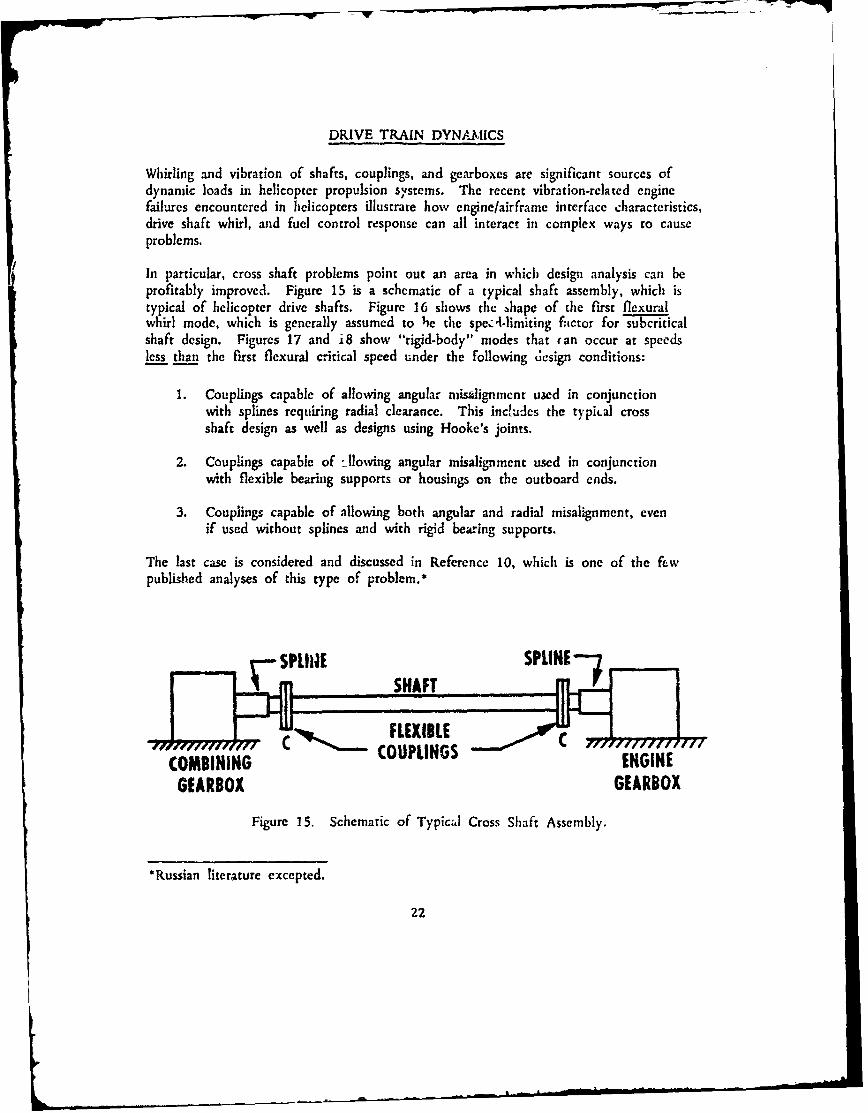
Whirling and vibration of shafts, couplings, and gearboxes are significant sources ofdynamic loads in helicopter propulsion s'stems. The recent vibration-related enginefailures encountered in helicopters illustrate how engine/airframe interface characteristics,drive shaft whirl, and fuel control response can all interact in complex ways to causeproblems.
In particular, cross shaft problems point out an area in which design analysis can beprofitably improved. Figure 15 is a schematic of a typical shaft assembly, which istypical of helicopter drive shafts. Figure 16 shows the !hape of the first flexuralwhirl mode, which is generally assumed to he the spe.-limiting factor for subcriticalshaft design. Figures 17 and i8 show "rigid-body" modes that (an occur at speedsless than the first flexural critical speed under the following design conditions:
1. Couplings capable of allowing angular misdignment used in conjunctionwith splines requiring radial clearance. This inctudes the typiLal crossshaft design as well as designs using Hooke's joints.
2. Couplings capable of llowing angular misalignment used in conjunctionwith flexible bearing supports or housings on the outboard ends.
3. Couplings capable of allowing both angular and radial misalignment, evenif used without splines and with rigid bearing supports.
The last case is considered and discussed in Reference 10, which is one of the fewpublished analyses of this type of problem.*
SPLINE SATSPLINE-"
COMBINING C'COUPLINGS EGNGEARBOX GEARBOX
Figure 15. Schematic of Typical Cross Shaft Assembly.
*Russian literature excepted.
22

C C
Figure 16. First Flexural Mode Shape for Drive Shaft.
Figure 17. Rigid-Body Mode Shape, Cylindrical Whirl.
Figure 18. Rigid-Body Mode Shape, Conical Whirl.
Rigid-body modes, which can occur in many drive shaft configurations using flexiblecouplings, are often ignored in the preliminary design analysis of a helicopter propul-sion system. If whirling problems occur at a later stage of development, these modesmay then be investigated, but the analytical tools generally used for this purpose havesome or all of the following limitations:
1. The whirling problen; is represented by a lateral vibration model.
2. As a result of 1, gyroscopic moments and the coupling of whirl with lateralvibration of housings are often neglected.
3. The effect of rotational acceleration on whirl is neglected.
4. The effect of internal friction in couplings, splines, sieeves, or U-joints isneglected.
These problems have been generally overlooked or underestimated in the past because= unbalance response in synchronous rigid-body whir! modes . usually limited in ampli-tude by nonlinearities or discontinuities in system parameters, thus allowing passagethrough these critical speeds without dire consequences. However, the last-mentionedeffect of internal friction can cause a drive shaft to become unstable and self-destructive at speeds above the rigid-body criticals. Cases of severely violent whirl inshaft-coupling systems which have been observed in past development programs havesometimes been attributed to this effect, but the solution has usually been to changethe design%. thus prevearing verification of the hypothesis or analysis of the cause.
'Such as a change to a different type of shaft coupling, perhaps sacrificing desirableLL-iracteristics of the original coupling that was the basis of its choice.
23

low!
A quote from Reference 10 describes the situation for a particulai type of coupling,but it applies to many other configurations as well:
"A significant feature of the results for this example is thewide gap which exists between the second and third .riticalspeeds. This gap may provide a suitable region for highspeed, super-critical applications. Such operations could per-mit the Bossier couplings to be designed with more misalign-ment capability and with less weight. Supercritical operationalso opens the possibility for very smoothly operating designswhich employ dynamic self-balancing. However, it is importantto note that a potential problem area also exists. The built-upnature of the Bossier coupling creates a possibility for awhirling instability involving non-synchronous precession (Reference11) when operated above the first critical speed. The dynamicstability characteristics of supercritical systems employing Bossiercouplings are unknown at present."
It is important to note that the critical speeds referred to above are rigid-body criti-cals, not the flexural criticals which are often used as criteria for shaft design andwhich the research on supercritical shaft design by Battelle Memorial Institute"1 wasrelated to.
A report of whirling induced by internal friction in a pinion shaft test rig is givenin Reference 12. Reference 13 reports a similar occurrence and the "fix" for aturbine engine rotor shaft.
The source of internal friction inducing the whirl reported in Reference 13 was aspline coupling. In analyzing the problem, the spline friction force had to be calcu-lated from assumed values of the friction factor, since no appropriate data on splinefriction was available.
The tendency for whirl speed to remain constant regardless of shaft speed, a charac-teristic of friction-induced whirl, is illustrated by an experimental observation fromReference 12:
"Rotating single-mass systems with large spans continued towhirl at the natural frequency as the rotating speed increasedto twice that frequency."
This could be a partial explanation of the wide discrepancies sometimes noted betweenvibration measurements made on the same helicopter propulsion system by differentinvestigators, since filters are sometimes used which admit only the frequenciesexpected at speeds synchronous with the various rotational speeds.
Even if 'he rigid-body modes in a drive train do not result in friction-induced whirlinstability, the synchronous response to unbalance can cause rapid wear of couplings.
24

splines, and bear:ngs, especially during start-up. when grease may be cold and clearancesmay be large.
It is therefore recommended that a study be made to identify al of the specific rigid-body shaft whirl modes that can and do occur in contemporary helicopter propulsionsystems, and that analyses be conducted to determine ways to reduce the magnitudeof response to these modes and to ensure stability under all operating conditions,
In order to effectively apply the results of this study, it "rili be necessary to havedetailed information on the dynamic properties (such a,. stiffness, damping. etc.) of thediffere nt types of couplings now in use or being considered for use. It is thereforerecomrr,.nded that experimental studies of these properties be made and methodsdeveloped for predicting these properties under various operating conditions.
One of the oldest and simplest types of shaft coupling is the Hooke's joint, or univcr-sal joint. This coupling has proved to be efficient and reliable in many applicationsfor transmitting torque while accommodating misalignments. but recent high-speedapplications have proved troublesome. As a result, other more expensive types ofcouplilzgs have been developed for high speeds which sacrifice some of the desirableproperties of the U-joint associated with its simplicity.
At high speeds. the dynamics of a shaft with U-joint couplings are quite complex.This is due in part to the oscillating speed characteristic of the coupling and in partto its bearing friction which plays the part of the internal friction discussed above.As a result, when past experience with U-joint couplings in low-speed applications hasbeen applied to high-speed power transmission shafts, problems of whirl and vibrationhave been encountered.
It is possible that a more complete understanding of the dynamics of shafts withU-joint couplings can make possible an advantageous use of these couplings in high-speed applications
It is therefore recommended that a study be made, preferably both analytical and ex-perimental, to determine optimum design criteria for smooth and efficient operation ofshafts with U-joints at high speeds for helicopter applications. Reference 14, whichtreats torsional dynamic effects and bending moments induced by misahgnment. maybe found helpful as a starting point.
Finally, shaft couplings should be recognized as potential fransmitters of vibration fromone component to another in a drive train, as well as sources of excitation.
For example, the engine-to-transmission drive shaft on the UH-1 helicopter uses aspherical spline coupling to accommodate misalignment between the rigidly mountedengine and the compliantly mounted transmission. The transverse vibratory shear3 andmoments transmitted by spline friction across the interface are unknown quantities. Itcan be surmised that these shears; and moments vary with spline clearance. lubrication,misalignment, transmitted torque, vibratory velocity or displacement, and vibratory fire-quency.
25

It is recommended thar measurements be made on existing heiicop'ers to determie thl-magnitude of the transverse vibratorv shears and muments transmitted across splineshaft couplings used in power transmission ,natts.
if these measurements indicate that the transmitted shears and moments arc stigfica.-
it is recommended that experimental and analtiical research be carried o.t to dew,mi:t how they vary with the factors listed above or with any other factors found tobe significant.
It should be possible to predict analytically the transverse shears and morment- trans-mitted across other types of couplings by using information obtained from the stud-es
of coupling dynamic properties which were recommended earlier for Shaft whi ana! -sis.
TORSIONAL STABILITY OF HELICOPTER DRIVESWITH AUTOMATIC FUEL CONTROL
Although this topic propedy belongs in the preceding section on drive train dynamics,it has been treated independently by SAE-Aerospace Recommended Practice 704 be-caust; of its connection with automatic speed governors. and accordingly it is treatedas a separate topic here.
In tile past, the approach to designing helicopter drive systems with automatic speedcontrol has been to define a set of fuel control charactetistics which, when combinedwith a pr-etermined mechanical drive, would result in acceptable control resporisewithout objectionable oscillations or instabilities. This approach has not alway., led tooptimum speed control ch.iracteristics, since the desired high gain of tile governormu-s sometimes be sacrificed to ohtain stability.
The methods and tools presently available for stability analysis are not always s , ZSS
ful in predicting conditions for torsional itability in helicopter propulsion s)stems.This is due in part to the linear restrictions on analytical tests for stability and inpart to the designer's incornplete knowledge of s)4.em parameters.
For example, Reference 15 reports on stability problems encountered in a mediumtransport helicopter which were not predicted by the initial design analysis. A Holzertorsional analysis initially predicted a natural frequency involving rotor blade lagmotion which turned out to be about 25 percent too low. A study of systeri-parameters eventually revealed that the lag damper characteristics used in the analysiswere in er"or. It is significant that the final solut*--'i was to reduce tile fuel controlgain, since a proposed modification to the lag damper was reported to produceunacceptable ground resonance characteriztics. It can also be observed that a fuelcontrol mocification is usually less expensive to an airframe manufacturer than a.esign cha-ge in the helicopter drive train or rotor.
Another point of significance in this example is that analytical predictions of drivetrain response were ultimately made from digital simulations, marching out step-by-stepsolutions to the equations of motion for each test case. That is, linear servo analysiswas not adequate for the problem due to the inherent nonlinearities and Lomplexityof the system. Computational expense could have been greatly reduced or eliminatedif a satisfactory method had been available for finding regions of stability in conciseform for complex nonlinear systems.
One :ossibility is to extend the present methods for predicting stability of linearsystems to include "equivalent linear" systems. That is, the significant nonlinearitiesin a drive train and governor might be represented by predictable linear characterist;.'_r,to produce nearly the saine resporn-e.
27

Another possibility is to apply the second method of Lyapunov, which is the mostgeneral approach currently available for the study of strbility in dynamic systems. 1 6
The generality of the method is the basis of considerable difficulty encountered indeveloping systematic techniques for its application to specific classes of problems.Significant work has been done, however, toward developing methods which are wellsuited to high-speed digital computation of the "Lyapunov functions"."7
A second-rate substitute or first-class companion to the development of better stabilityanalyses would be the development of faster and more efficient marching solutions fordigital simulation. For example, a method for direct application of Hamilton's princi-ple to the derivation) of first-order difference equations for c' namic systems has beenderived by the author of tiis report.18 Since this method eliminates the need totake second derivatives in writing equations of motion and thereby eliminates one ofthe usual steps in machine computation,* it should be possible to :reduce man .:nd/ormachine effort in obtaining solutions to test cases.
IL is therefore recommended that studies be made to develop improved methods forstability analysis of complex ,nonlinear drive systems with closed-loop fuel control,and/or methods for more rapid digital simulation of drive train dynamic response.
As pointed out in the introductory paragraphs to this section, the usual solution todrive train torsional instabilities is to modify the fuel control characteristics. This isbecause modifications to the inechanical components of already existing shafts, traris-missions, and rotors are costly and sometimes result in less-than-optimum systemperformance by some other criteria. On the other hand, the modifications usuallynecessary to the fuel control to obtain stability often result in poor speed controlresponse chat -_teristics.
It is possible that new mechanical components for helicopter drive trains can bedeveloped which will allow improvements in speed control response without sacrificingtorsional stability.
For example, Reference 19 describes the design and application of a shaft couplingwhich uses centrifugal force to provide a zero torsional stiffness characteristic at apartirular point on the torque-speed curve. The zero stiffness property of the cou-pling effectively decouples the torsional inertias on opposite sides of the coupling andhas been found to eliminate the first resonant mode completely and to reduce thesecond mode significantly in a two-degree of-freedom shaft-rotor system. The couplingis now in service in a tugboat drive, with one of the previously resonant torsionalfrequencies completely eliminated. A similar coupling developed in Russia is describedin Reference 20.
it is recnmmended that the application of zero-torsional-stiffness couplings to helicopterdrive shafts be investigated with the objective of eliminating or favorably modifyingresonant modes of tormicnal oscillation.*For c.imple, in the Runge-Kutta integration algorithm, the exact first integrals of
many of the accelerations are obtained without numerical integration.
28

It is also recommended that favorable consideration be given to the development ofrany other mechanical devices which appear capable of enhancing the torsional stability
of helicopter drive trains without compromising speed control characteristics.
29

CONCLUSION
The basic conclusion of this report is that the reliability and performance of U. S.Army helicopters can be improved by specific research and development work in theareas of -enine/Airirarne vibratory compatibility, power transmission shaft dynamics,and- drive systemnIgovernor stability. The programs which appear to offer the greatestpotential for przctical --esulrs at the present time are described in the Summary ofRecommendations.
30

SUMMARY OF RECOMMENDATIONS
1. It is recommended that existing flight test data on engine vibration inhelicopters be analyzed to determine:* The spectrum of engine vibration amplitudes for typical military
missions.
* The relative contributions of engine and airframe to engine vibration.
0 Amplitude versus discrete frequency over the _range of 10 to 10,000 Hzfor flight conditions dominating the mission -profiles.
0 Predominant responding mode shapes for the engine, both rigid-bodyand flexural.
A list of some of the presently available flight test data is given in Appendix
2. It is -recommended that additional flight test data be acquired- fim a repre-sentative group of the different types of helicopters (i.e , :smgle rotor, iandemrotor, two blades, four blades, etc.) for analysis as described in recommenda-tion 1.
3. It is recommended that a study be made to determine the extent to whichvibration-related engine component failures can be reliably related to vibratoryvelocity alone (with no frequency dependence). This study should consiacof two phases:
* A survey of vibratory engine failure histories made in conjunction withvibration surveys (flight test data analyses) of the- same engine installa-tions.
* Analysis to relate vibratory strain in engine sti ctural components tovibratory velocity measured at t,-e locations recommended by enginemanufacturers.
4. It has been observed that measured engine vibratory velocity tends to remainconstant over a wide frequency range. It is recommended that a study bemade to rationalize this observation on a sound theoretical basis, thus im-proving our understanding of engino vibratory response to both internal andexternal excitation.
31
J. It is recommended that investigations be conducted to determine therelationship of vibration at recommended points of measurement t. vibratoryresponse of critical engine components, especially rotors. With regard toengine rotor response, it is recommended that special attention be given tothe eff.-ct of the squeeze film betiring dampers bei'- used in many -ecen:engine designs.
6. It is recommended that an investigation be made to determine the bestme,.thods for measuring engine rotor flexure under opera.ing conditions, andthat the most promising methods be developed to a statz that will encouragetheir use.
7. It is reconmnuded that vibration data on future helicopter development pro-grams be acquired and analyzed in suficient detail to identify both ampli-tudes and modes of responses until enough is known ;,bout engine vibratorylmits to allow a simplification of methods without sacrificing predictabilityof failures, The identification of modes will usually require phase data inaddition to frequency data, and will also require inteiligent placement oftransducers at mote locations than is presently customarv
8. It is recommended that impedance-mobilitj methods be developed forenginelairframe vibratory interface analysis. A primary objective should beto achieve optimum use of mobilities obtained from shake tests or f-omexisting computer piwgrams in the overall analysis. A list of some eyistingcomputer programs is given in Appendix I1.
9. It is believed that problems associated with rigid-body whirl modes* inhelicopter drive shafts with flexible couplings have been treated too lightlyin design analysis, it is therefore recommended that a study bc made toidentify all of tfe specific rigid-body shaft whirl modes thac can and dooccur in contemporary helicopter drive trains, and that analyses be conductedito determine methods for reducing the magnitude of response to these modesand ensurhig stability under all operating conditions.
10. It is recommended that experimental studies be made to determine thedynamic properties, such as stiffness, damping, and inertia, of the differenttypes of shaft couplings now in use or being contemplated for use. Athoughsorme of these properties are known and available, they are inc.implete foran adequate dynamic analysis. In making these studies, shaft couplingsshould be recognized _. potential transmi::ers of vibration from one com-ponent to another in a drive train, as well as sources of excitation.
-Modes that cannot be deter.nined simply from a consideration of lateral bendingvibration of shafts, modeled as beams.
32
11. It is recommended that an analytical and experimental study be made todetermine optimum design criteria for smooth and efficient operation ofshafts with Hooke's joints at high speeds for helicopter applications.Reference 14, which treats torsional dynamic effects and bending momentsinduced by misalignment, may be helpful as a starting point. The effectsof flexible bearing mounts or support housings should not be neglectedunless they are proved to be insignificant for a particular configuration.
12. It is recommended that the magnitude of the transverse vibratory shearsand moments transmitted across spline shaft couplings used in power trans-mission shafts be measured on existing helicopters. if these measurementsindicate that the tra,.mitted shears and moments are significant, it Lrecommended thrr experimental and analytical studies be made to determinehow they vari with the pertinent parameters, such as spline clearance, mis-alignment, a:id transmitted torque.
13. It is believed that the methods presently used fer torsional stability analysisof governor-controlled rotor drive systems are not adequate for the problemsbeing encountered. It is therefore recommended that studies be made todevelop improved methods for stability analysis of complex nonlinear drivesystems with closed-loop fuel control, and/or methods for more rapid digitalsimulation of drive train torsional response.
14. It is recommended that the application of zero torsional stiffness couplingsto helicopter drive shafts be investigated with the ojective of eliminatingor favorably modifying resonant modes of torsional oscillation. It is alsorecommended that favorable consideration be given to the development ofany other mechanical devices that appear to be capable of enhancing thetorsional stability of helicopter drive trains without compromising speed con-trol characteristics.
33

LITERATURE CITED
1. Ketchel, J. M., Danaher, J. W., and Morrissey, C. J., EFFECTS OF VIBRATIONON NAVY AND MARINE CORPS HELICOPTER FLIGHT CREWS, Matrix Re-search Co. Report for tho Office of Naval Research, August 1, 1969, AD 698194.
2. Balke, R. W., A REVIEW OF TURBINE ENGINE VIBRATION CRITERIA FORVTOL AIRCRAFT, Joint S% mposium on Environmental Effects on VTOL Designs,American Helicopter Society Preprint No. SW-70-18, November 1'970.
3. White, R. F., Paper presented at 14th Meeting of Mechancal Failures PreventionGroup, Office of Naval Research, Los AngeleS, California, JZ.h,• y 25, 1971.
4. Plunkett, R., MECHANICAL IMPEDANCE METHODS FOR MLCHANICAL VI-BRATIONS, a compilation of papers from the ASME Annual Meeting, New York,December 2, 1958.
5. Mard, K. C., and von Hardenberg, P. W., TURBINE ENGINE DYNAMIC COM-PATIBILITY WITH HELICOPTER AIRFRAMES, Shock and Vibration Bulletin 39,Part 3. January 1969, pp. 17-30.
6. On, F. J., and Besheim, R. 0., A THEORETICAL BASIS FOR MECHANICALIMPEDANCE SIMULATION IN SHOCK AND VIBRATION TESTING OF ONE-DIMENSIONAL SYSTEMS, NASA TN D-1854, August 1963.
7. On, F.J., MECHANICAL IMPEDANCE ANALYSIS FOR LUMPED PARAMETERMULTI-DEGREE OF FREEDOM/MULTI-DIMENSIONAL SYSTEMS, NASA TND-3865. May 1967.
8. Flannelly, William G., Berman, Alex. and Barnsby, Roger M.. THEORY OFSTRUCTURAL DYNAMIC TESTING USING IMPEDANCE TECHNIQUES,VOLUME I - Ti-HEORETICAL DEVELOPMENT, Kaman Aerospace Corporation;USAAVLABS Technical Report 70-6A, U. S. Army Aviation Materiel Laboratories,Fort Eustis, Virginia, June 1970, AD 874509.
9. Berman, A., and Flannelly, W. G., THE "r9EORY OF INCOMPLETE MODELSOF DYNAMIC STRUr-rURES, presented L, the AIAA/ASME lth Structures,Structural Dynamics and Materials Conference, Denver, Colorado, April 22-24.1970.
LO. Mayerjak, R. J.. and Bossier, R. B., Jr., THE BOSSLER COUPLING. NASACR-1241. January 1969.
34

11. Prouse, R. H., Meacham, H. C., and Voorhees, J. E., THE DESIGN ANDEVALUATION OF A SUPERCRITICAL-SPEED HELICOPTER POWER-TRANSMISSION SHAFT, Jr-urnal of Engineering for Industry, November 1967,pp. 719-728.
12. Seirig, A., WHIRLING OF SHAFTS IN GEARED SYSTEMS, Journal ofEngineercg for Industry, May 1967, pp. 278-284.
13. Williams, R., Jr., and Trent, R., THE EFFECTS OF NONLINER ASYMMET-RIC SUPPORIS ON TURBINE ENGINE ROTOR STABILITY, SAE Paper700320, presented at the National Air Transportation Meeting, New York, N.Y.,April 20-23, 1971.
14. Bossier, R. B., Jr., and Flannelly, W. G., HOW TO PREDICT DRIVE-TRAINVIBRATION CAUSED BY HOOKE's JOINTS, Machine Design, June 18, 1964,pp. 194-198.
15. Rumford, K., Fredrickson, C.. and Stcphenson, C., FACTORS AFFECTINGFUEL CONTROL STABILITY OF A TURBINE ENGINE/HELICOPTER ROTORDRIVE SYSTEM, presented at the 27th Annual National V/STOL Forum ofthe American Helicopter Society, Washington, D. C., May 1971.
16. Kalman, R. E., and Bertram, J. E., CONTROL SYSTEM ANALYSIS ANDDESIGN VIA THE SECOND METHOD OF LYAPUNOV, Journal of BasicEngineering, June 1960, Part I, pp. 371-393, Part II, pp. 394-410.
17. Weisse~iburger, S., STABILITY ANALYSIS OF RELAY-CONTROL SYSTEMSVIA THE DIRECT METHOD OF LYAPUNOV, NASA CR-320, October 1965
18. Vance, J. M., and Sitchin, A., DERIVATION OF FIRST-ORDER DIFFERENCEEQUATIONS FOR DYNAMICAL SYSTEMS BY DIRECT APPLICATION OFHAMILTON'S PRINCIPLE, Journal of Applied Mechanics, June 1970.pp. 276-278.
19. Chapman, C. W., ZERO (OR LOW) TORSIONAL STIFFNESS COUPLINGS.Journal of Mechanical Engineering Science, February 1969, pp. 76-87.
20. Balzhi, M. F., and Esin, G. D., FLEXIBLE METALLIC COUPLINGS WITHDYNAMIC LINKS, The Engineer's Digest, Vol. 21, No. 4, April 1960,pp. 98-99.
35

APPENDIX IIMPEDANCE - MOBILITY METHODS FOR VIBRATION ANALYSIS
Impedance - mobility methods are ideally suited for steady-state vibration analysis ofcomplex structures when the following conditions prevail:
* Vibration is to be measured at only a few selected points in the structure,and the response of these points is to be predicted by analysis.
• It is desired to ccmbine experimental measurements with the analyticalmodel so as to improve the accuracy of simulation.
* It is desired to predict the effect of changing specific elements in isolatedparts of the structure or at an interface
* It is desired to predict the vibratory response of an assemblage of com-ponent structures, when the vibratory response of each component isknown.
Impedance - mobility methods were first developed by electrical engineers for circuitdesign analysis, and they were later adopted for vibration analysis by some mechanicalengineers. However, acceptance of these methods has not been widespread in themechanical engineering field, mainly because they arc so often presented in terms ofelcctrical analogies. An excellent elementary position of these methods is given inpurely mechanical terms in Reference 4. The remainder of this appendix will bedevoted to summarizing a few of the basic features of mobility analysis and motiva-ting their application to helicopters.
In mobility analysis it is convenient to express vibratory force and velocity as com-plex quantities:
i'otf = Fe F (cos ot + i sin w.t) (1)
iWtv = Ve V (cos Wt + i sin ct) (2)
where F and V in general are complex.
In linear vibration analysis of lumped parameter systems, the three basic physicalelements are the mass. damper, and spring. The equations of equilibrium for thesecomponents arc
mass: Mn f 31
damper: cv =f 4
36

t
~f- spring: ' d 5)
to
Snbstitution of Equations (1) and (2) into (3). (4), and (5) yields
mass: iotaV = F (6)
damper: cV = F (7)
kspring: - V F (8)
It should be recalled that the imaginary component of a complex vector correspondsto the sine term of harmonic motion while the real component corresponds to thecosine term. Thus the complex notation expresses both the amplitude of a vibratoryvector (given by the modulus) and the phase angle.
Mechanical impedance is defined as the ratio of vibratory force to vibratory velocity,
F~zrV
Mobility is the inverse of impedance and is therefore defined as the ratio of vibratoryvelocity to vibratory force.
V IF Z
The choice of either impedance or mobility as a working quantity is basically arbi-trary, but may be influenced by special characteristics of the problem of interest.Mobility will be used in this report, because velocity is the quantity to be measuredmost often, while the excirttion will often be expressed in terms of force.
If the velocity and force are taken at the same point in a structure, the resultingmobility is called "driving point mobility". if the velocity and force are taken atdifferent locations, the resulting mobility is called "transfer mobility".
Every element or combination of elements in a structure has a characteristic mobility.The mobilities of the three basic physical elements are obtained from Equations (6).(7). and (8). as shown in Figure 19. by dividing the relative velocity across eachelement by the exciting force. Special notice should be taken of the fact tilat theve!ocity of one side of a mass element must always be taken as zero. since Newton'sSecond Law is valid only in an inertial reference rrame. That is. the velocity usedto obtain mass mobility must be absolute.
Mobilities of combinations of elements are obtained in exaztly the same way, and theanalysis o any structure is reduced to the solu,;on of a set of algebraic equar-ons bythe requirements of velocity compatibility and force equilibrium.
37

000
M ass -7
Mo t = I from Equation (6)
v, rv,+v
C
000 000
Damper = =-V from Equation (7)Mobility = c F c
Spring _ fromMobility-- F m Equation (8)
Figure 19. Mobilities of the Basic Elements.
38

I For example, consider a damper, spring, and mass connected ;n ser~es and excited bya harmonic force generator. A mobility schematic is shown in Figure 20, with thelinks numbered to identify for-cs.
C Fe~J
Figure 20. Mobility Schem-atic for- Damper. Spring, and Mass in Scries.
The mobility ecquaions are
v - v2 1 V - V3 i(I- V3 IF, c F2 - ; F 3 w irn
and equilibrium of forces requires
F, F = P3 = F
The driving point mobility which the force generator 'looks in to" is calculated as
V V_ 1 V 2 - V ,i2 V3 13
Mt V, V, - V, V, - V3 V3M, +F F F F
l iw 1c+ T +
- mwk + ic 1wom - k,mnwkc
39

-w
which illustrates the basic rule that mobilities connected in series can be added toobtain the mobility of the resu!ting assembly. The transfer mobility for velocity V,is
V2 V, V1 - V2, 7 7 F j= - -
(c,2m - k)
kwm
Figure 21 shows the mubility dchrnatic of the sane elements connected in parallel.The mobility equations are
V, V2 ico I 1
F WmI'F 3 k F4 c
The equilibrium of forces requires
F = F, + F, ; F, 3 + F4
and the compatibility of velocities requires V, = V'.
The driving point mobility seen by t.e force generator is calct_;ated as
V, m N1k Me
F Mk Mc + M Mc + M Mk
=V
3
ii
4. 1
00 0 *7i

To illustrate applications of these techniques, consider the problem of determining thevibratory response of a turboshai. engine to rotor unbalance if thle response is to bemeasured at an external location onl ti'u entine case. A grc. 'v simptlified model of thethe rotor/case assembly is shown in Figure 22. The case wiq reseitted by a uniformbeami of mnass per unit length p and stiffness El .The rotor is represented by amassless shaft carrying a centrally located disc cf mnass Md .The bearing support:engine mounts are represented by springs of stiffnless kBI2 and krn/ 2 respectively.
Figure 23 shows thle mobility model with rotor disc unbalance represented by a forcegenerator. The engine cakse is reduced to a single -degree-o f- free dotm system in thlei-obility model. thus preserving oi-ay the fundamcnal mode. Thle case 'atiffuiess and
ro ' tffness are repiresented by kc and kR respectively.
K- e ---W
Figure 22. Simplified tv4-idel of Engine Case/Rotor Assembly,
4
f4O
Figure 23. Mobility Model for Responst. of Case to Rotor Unbalance.
414

It ;,s desired to compare the vibratory velo-:-y at locations B at~d C on the enginecase to the response of the rotor disc. The ;nobility equations are
Vi I VI - V2 iW2
F2 ioA2 md F3 kRB
V 2 - V 3 iw,') V 2 4(02
F4 kc FS kin
V3 I
F 4 'W2TMc
and the equations for equilibrium of forces are
F, = F2 + F 3 ; F3 = F 4 '+ FS
Taken together, these rct:esent a system of seven algebraic equations in seven un-knowns, which can easily be reduced by substitution to the following third-oidermatrix equation:I-
(2o' md - kRB) kRB Vio
kc (W2m - kc) V2 0
kRB )(km + kRBM j m V3
Cramer's rule yields the solution as
kc Owm + (km + kR. w2, c kc) 2 C C)Vi = Vd = -D oW2FI)
kRB (2 mc - kc) 2 F,-~V V = Vb = D ( ,F
-kRBk cV3 = Vc - D J (i 2F, )
42

D (kc + km) (WI lm d - kRB) (w2im c - kc) + kc (tl 2 md - kRB)
+ kRBw 12 md (w) 2 m
c - kc).
Of special interest are the ratios of rotor disc response to !.ae response which wouldbe measured at locations B and C:
Vi Vd km + kRB k com cV2 Vb kRB k (o~mc - kc)
V, Vd km (Wm - kc) + kRB W2 mc
V3 Vc kRBkc
Inspection of the solutions shows that the rotor disc response Lan be very large evenwhen the measured response on the case is zero. For example, if
Vb - 0 (antiresonance, kc = o2mc)
iw02 F1Vd = (A22md - kRB)
Mobility (or impedance) analysis of large and complex structural assemblies is facilita-ted by the application of special matrix techniques as described and/or used inReferences 4 and 8.
The mobility approach is made especially powerful for analysis of the effects ofchanging or inserting individual elements in a complex structure by the use ofThevenin's theorem and Norton's theorem.
Consider a system which is to have an element (or combination of elements) installedbetween -wo junction points, say, points 1 and 2. Figure 24 illustrates the concept,with the mobility of the added element represented by M e .
rfLi_liI I I
I RURUE I STRUCTUREI
Figure 24. Mobility M e Added Between Two Points in an Existing Structure.
43

__ -
The force and relative velocity across mobility Me installed in the structure, with all
force and velocity generators activated, can be determined from an analysis of arelatively simple equivalent system given by Thdveni's rheorera. Thdvenin's equivalentsystem is shown :a Figure 25, where
me = mobility of the added elemint
Mi "- driving point mobility of point 2 with respect to I with all generatorsdeactivated (a deactivated ve zmty generator becomes a rigid link whilea deactivated force generator disappears) and no Me
Vo = free velocity V, - V, with all generators active and no Me.i- v, 7 - V2
Figure 25. Thdvenin's Equivalent System.
An alternate equivalent system which can be constructed from Norton's theorem isshown in Figure 26, where Fb is the "blocked force" that would be transmittedthrough a rigid link if it were inserted to prevent relative motion of points 1 and 2when the generators are activated. The mobilities Me and M; are defined the same asfor Thdvenin's equiva!ent system. An example of direct application of Norton'sequivalent system is the determination of vibratory force and velocity across a softengine mount to be installed between an engine and airframe. The blocked force Fbwould be the force measured or calculated in a rigid engine mount at the samelocation.
Figure 26. Norton's Equivalent System.
44

APPENDIX 11COMPUTER PROGRAMS CURRENTLY IN USE OR
AVAILABLE FOR HELICOPTER ENGINE/AIRFRAME VIBRATION ANALYbIS
The major specialized computer programs for engine/air frame vibratory analysis wvithwhich the author of th~is report became familiar d-iring the study preceding the reportarc listed below. The list is intended solely a3 a convenience for future researchersin this area and does not constitute in any way a commendation by inclusion or acriticism by omission of any contractor or o~ther organization. All of the helicopterengine and airframe contractors have general analytical capabilities which may not beincluded in the list.
1. VAST, "System Vibration and Static Analysis"
a. Source and User: General Electric, Aircraft Engine Group, Lynn,Massachusetts.
b. Description: Based on Prohl's method for calculating critical speeds ofrotors and expanded to include the engine frame and associated componentsmodeled as bLams. Effects of bearing clearances, squeeze film dampers,aircraft maneuver loads, etc., have been added. Calculates critical speeds andforced response of turboshaft engines.
C. Pertinent refe-ences:
(1) Sevcik, J. K., "System Vibration and Static Analysis", ASME Paper No.63-AHGT-57, presented at the Aviatioti and Space, Hydraulic, and GasTurbine Conference and Products Show, Los Angeles, California, March3-7, 1963.
(2) Prohil, M. A., "A General Method for Calculating Critical Speeds ofFlexible Rotors", journal of Applied Mechanics, September 1945, pp.A-142 through A-148.
2. Critical Speed Analysis of Turbo Rotor Systems (Lycoming)
a. Source and User: Lycoming Division, Avco Corporation, Stratford,Connecticut.
45

b. Description: Based on a planar multiple beam model that allows reasonablyaccurate predictions for critical speeds but which is dependent on an accurateknowledge of damping for reliable predictions of forced response. The capa-bility exists for determining the response to shock or impulse inputs at theengine mounts. The program calculates both critical speeds and foicedresponse of turboshaft engines.
c. Pertinent reference:
Bohm, R. T., "Designing Complex Turbo Rotor Systems With ControlledVibration Characteristics", SAE Paper No. 928B, presented at the NationalTransportation, Powerplant, and Fu-ls and Lubricants Meeting, Baltimore,Maryland, October 19-23, 1964.
3. COSMOS - USA, Dynamic Structural Analysis of Helicopter Airframes
a. Source a:d user: The Boeing Company, Vertol Division, Philadelphia.Pennsylvania.
b. Description: Based on the stiffness method for calculating eigenvalues of anelastic structure. Uses a "unified structural analysis (USA)" method whichavoids breaking a structure into substructures. Eigenvalues are obtained bysimilarity transformations. Mass elements are strategically located atrelatively few points in the model. The method is efficient but is not welladapted to studying the response of a small part of the structure in greatdetail (e.g., an engine or a transmission). Calculates critical frequencies andmode shapes of complicated structures and zssemblages.
c. Pertinent references:
(1) Sciarra, J. J., "A Computer Method for Dynamic Structural AnalysisUsing Stiffness Matrices", Journal of Aircraft, Vol. 6, No. 1, Jan.Feb1969, pp. 3-8.
(2) Kiersky, L. B., "COSMOS, A Computer Program for Structural Analysis",Doc. D2-4513, The Boeing Co., 1962.
4. NASTRAN. "NASA Structural Analysis Computer System"
a. Source; NASTRAN, Systems Management Office, NASA Langley ResearchCenter, Hampton, Virginia.
b. User: Bell Helicopter Co., Hurst, Texas.
c. Description: This program performs both static and dynamic structuralanalysis. The dynamic analysis solves for natural frequencies, mode shapes,
46

r jrtransient response in terms of modal coordinates, transient response in termsof grid-point coordinates, and forced response to a spectrum of harmonicinputs. Output is obtainable as curves against time or frequency, or as plotsof structural deformation at specific time intervals.
d. Pertinent references:
(1) Butler, T. G., and Michel, D., "NASTRAN, A Summary of the Functionsand Capabilities of the NASA Structural Analysis Computer System".
NASA SP-260, 1971.
(2) McCormick, C. W., "NASTRAN Beginner's Guide", MS 139-1, preparedfor NASA Langley Research Center, Hampton, Virginia, by the MacNeal-Schwendler Corporation.
t
47