Embed Size (px)
Citation preview

The content and copyrights of the attached material are the property of its owner.
Distributed by:
www.Jameco.com 1-800-831-4242
Declaration of RoHS Conformity To minimize the environmental impact and take more responsibility to the earth we live, MEAN WELL hereby confirms that the following product series comply with Directive 2002/95/EC of the European Parliament - RoHS (Restriction of Hazardous Substances). Content of Compliance Lead <0.1 % by weight (1000 ppm) Mercury <0.1 % by weight (1000 ppm) Cadmium <0.01 % by weight (100 ppm) Hexavalent Chrome (Cr+6) <0.1 % by weight (1000 ppm) PBBs <0.1 % by weight (1000 ppm) PBDEs <0.1 % by weight (1000 ppm) Product Series Please refer to the attached list for details. Delivery The actual delivery date for RoHS compliance products will depend on our inventory status. Please contact our sales representatives for details. How to Recognize The serial number on each PSU originally was Cxxxxxxxxx and right now will be changed to Rxxxxxxxxx or Exxxxxxxxx (or add “R” for serial number that only specify the production weeks) for RoHS compliance products for the ease of identification.
Jerry Lin / President MEAN WELL Enterprises Co., Ltd.

Product Family Series
G3 RS-25/35/50/75/100/150, RD-35/50/65/85/125, RID-50/65/85/125, RT-50/65/85/125, RQ-50/65/85/125
G2 S-25/40/60/100F/150/240, T-40, D/ID/T/IT/Q/IQ-60, D/T/Q-120, SC-150
PFC SP-75/100/150/200/320/480/500/750, USP-225/350, TP-75/100/150, QP-100/150/200/320/375
AD ADS-55/155, AD-55/155, ADD-55/155
CL/PL CLG-60/100, PLN-30/60/100
MDR-20/40/60, DR-30/45/60/75/100/120, DRH-120, DRP-240/480/480S, DRT-240/480/960, DR-RDN20, DR-UPS40 DIN
Modular MP-450/650/1K0, MS-75/150/300, MD-100
Parallel PSP-500/600/1000/1500, RSP-1000/1500, RCP-1000, RCP-1U
NFM-05/10/15/20, PM-05/10/15/20, PS/PD-25, PS-35, PS/PD/PT-45, PS/PD/PT-65, RPD/RPT-65, PD-110, PQ-100, PPQ-100, PPS/PPT-125, LPS-50/75/100, LPP-100/150, ASP-150, PPS-200, PID-250, MPS-30, MPS/MPD/MPT-45, RPS/RPD/RPT-60, MPS/MPD/MPT-65, RPS/RPD/RPT-75, MPS/MPD/MPT/MPQ-120, MPS/MPD/MPT/MPQ-200
Open Frame
Charger GC-30, PA/PB/PS-120, ESC/ESP-120, ESC/ESP-240, PB-300/360
Adaptor GS-06/15/18/25, ES-18/25, P25, P30, P40, P50, P66, U65S, MES-30/50, ATX-100, AS-120P
PC/IPC Power YP-350J, IPC-200/250/300
SD-25/50/100/150/200/350, SDM30, ASD10H/15H, NSD10/15, SBT, SFT, DET, SRS, SUS, SPR, SPU, SCW, SLW, SKE SKA, DCW, DLW, DKE, DKA, TKA DC/DC Converter
Inverter TN/TS-1500, A301/A302
Power Cord YP** + YC** ** For other products not listed above, please contact our sales representatives for availability
2007.04 update

SPECIFICATION
MODEL
DC VOLTAGE
RATED CURRENT
CURRENT RANGE
RATED POWER
OUTPUT VOLTAGE ADJ. RANGE
LINE REGULATION
LOAD REGULATION
SETUP, RISE TIME
HOLD UP TIME (Typ.)
VOLTAGE RANGE Note.5
FREQUENCY RANGE
EFFICIENCY (Typ.)INPUT
FUNCTION
INRUSH CURRENT (Typ.)
LEAKAGE CURRENT
OVER TEMPERATURE
WORKING TEMP.
CURRENT SHARING(CS)Note.7
OUTPUT VOLTAGE TRIM Note.6
DC OK SIGNAL
REMOTE ON/OFF CONTROL Note.6
AUXILIARY POWER(AUX)
WORKING HUMIDITY
STORAGE TEMP., HUMIDITY
TEMP. COEFFICIENT
VIBRATION
MTBF
DIMENSIONOTHERS
NOTE
PACKING
OVERLOAD
OVER VOLTAGE
AC CURRENT (Typ.)
300ms, 50ms at full load
16ms/230VAC 16ms/115VAC at full load
90 ~ 264VAC 127 ~ 370VDC
47 ~ 63Hz
12A/115VAC 6A/230VAC
25A/115VAC 40A/230VAC
<2.0mA / 240VAC
105 ~ 125% rated output power
Protection type : Constant current limiting, recovers automatically after fault condition is removed
13.8 ~ 16.8V 17 ~ 20.5V 27.6 ~ 32.4V 31 ~ 36.5V 56.6 ~ 66.2V
Protection type : Shut down o/p voltage, re-power on to recover
85 5 (TSW2 ) detect on heatsink of O/P diode; 75 5 (TSW1 ) detect on heatsink of power transistor
Protection type : Shut down o/p voltage, recovers automatically after temperature goes down
-20 ~ +60 (Refer to output load derating curve)
Power on : short between on/off(pin6) & -S(pin2) on CN50 Power off : open between on/off(pin6) & -S(pin2) on CN50
Open collector signal low when PSU turns on, Max. sink current :10mA
Adjustment of output voltage is possible between 40 ~ 110% of rated output
Please refer to function manual
5V @ 0.5A (+5%, -8%)
20 ~ 90% RH non-condensing
-40 ~ +85 , 10 ~ 95% RH
0.02%/ (0 ~ 50 )
10 ~ 500Hz, 2G 10min./1cycle, 60min. each along X, Y, Z axes
35K hrs min. MIL-HDBK-217F (25 )
295*127*41mm (L*W*H)
1.95Kg; 6pcs/12.7Kg/0.99CUFT
83% 85% 88% 88% 90%
0.5% 0.5% 0.5% 0.5% 0.5%
0.5% 0.5% 0.5% 0.5% 0.5%
1.0% 1.0% 1.0% 1.0% 1.0%
150mVp-p
10 ~ 13.5V
150mVp-p
13.5 ~ 16.5V
150mVp-p
20 ~ 26.4V
150mVp-p
24 ~ 30V
150mVp-p
43 ~ 55V
12V
60A
0 ~ 60A
720W
15V
50A
0 ~ 50A
750W
24V
40A
0 ~ 40A
960W
27V
37A
0 ~ 37A
999W
48V
21A
0 ~ 21A
1008W
RSP-1000-12 RSP-1000-15 RSP-1000-24 RSP-1000-27 RSP-1000-48
1. All parameters NOT specially mentioned are measured at 230VAC input, rated load and 25 of ambient temperature.2. Ripple & noise are measured at 20MHz of bandwidth by using a 12" twisted pair-wire terminated with a 0.1uf & 47uf parallel capacitor.3. Tolerance : includes set up tolerance, line regulation and load regulation.4. The power supply is considered a component which will be installed into a final equipment. The final equipment must be re-confirmed that it still meets
EMC directives.5. Derating may be needed under low input voltages. Please check the derating curve for more details.6. The power supply unit will have no output if the shorting connector is not assembled. It contains two shorting wires: one is from on/off(pin6) to -s(pin2)
and the other is from Vco(pin8) to Vca(pin10). Please refter to function manual for details.7. In parallel connection, maybe only one unit operate if the total output load is less than 5% of rated load condition.8. Please consult MEAN WELL for applications of more units connecting in parallel.
POWER FACTOR (Typ.) 0.95/230VAC 0.98/115VAC at full load
SAFETY STANDARDS
HARMONIC CURRENT
EMS IMMUNITY
UL60950-1, TUV EN60950-1 approved
Compliance to EN55022 (CISPR22)
Compliance to EN61000-3-2,-3
Compliance to EN61000-4-2,3,4,5,6,8,11; ENV50204, EN55024, EN61000-6-2, EN61204-3, heavy industry level, criteria A
1000W Single Output Power Supply RSP-1000 ser i es
RIPPLE & NOISE (max.) Note.2
VOLTAGE TOLERANCE Note.3
EMI CONDUCTION & RADIATION
WITHSTAND VOLTAGE
ISOLATION RESISTANCE
I/P-O/P:3KVAC I/P-FG:1.5KVAC O/P-FG:0.5KVAC
I/P-O/P, I/P-FG, O/P-FG:100M Ohms/500VDC
ENVIRONMENT
SAFETY &
EMC(Note 4)
PROTECTION
Universal AC input / Full range
AC input active surge current limiting
Built-in 5V/0.5A auxiliary power
Built-in active PFC function, PF>0.95
Protections: Short circuit / Overload / Over voltage / Over temperature
Output voltage can be trimmed between 40 ~ 110% of the rated output voltage
Forced air cooling by built-in DC fan
Active current sharing up to 4000W(3+1)
DC OK Signal
Built-in remote ON-OFF control
Built-in remote sense function
3 years warranty
(Note.8)
High power density 10.7w/inch
1U low profile 41mm
3
Features :
..

Mechanical Specification
Derating Curve Static Characteristics
Case No. 952B Unit:mm
LO
AD
(%
)
INPUT VOLTAGE (VAC) 60Hz
90 95 100 115 264
90
100
80
70
60
50
40
Block Diagram
AMBIENT TEMPERATURE ( )
LO
AD
(%
)
20
40
60
80
100
-20 0 10 20 30 40 50 60 70
Ta=25
PFC fosc : 110KHz
PWM fosc : 90KHz
FAN
O.V.P.
-V+VRECTIFIERS
&FILTER
-S
+S
CIRCUITDETECTION
POWERAUX
REMOTECONTROL
ON/OFF
FILTER&
RECTIFIERSAUX POWER(5V/0.5A)
SHARINGLOAD
CS
DC-OK
LIMITING
ACTIVE
CURRENTINRUSH
CONTROL
INGI/P SWITCH-
POWERRECTIFIERS
FILTEREMI
PWM
&PFC
PFCCONTROL
O.T.P.
O.L.P.
AC Input TerminalPin No. Assignment
Pin No.
1
3
2
Assignment
FG
AC/L
AC/N
CN502
12
1
11
TB1
3
2
1
7
+V
-V
3-M4 L=6
20
.5
SVR51Air flowdirection
41
12
7
18
.5
3-M4 L=4
90
10
6
277.7
25
.47
.8
21 34.5
59
295
3-M4 L=6
277.7
25
.47
.86
20
.5
Control (CN50) : JST B12B-PHDSS or equivalentpin number assignment
Pin No.Pin No.Pin No.
951
106
11,127
8
2
3
4
AssignmentAssignmentAssignment
VciDC-OK+S
Vca
GND
-S
CS
ON/OFF
Vco
G-AUX
5V-AUX
Mating Housing
JST PHDR-12VSor equivalent
Terminal
JST SPHD-002T-P0.5or equivalent
1000W Single Output Power Supply RSP-1000 ser i es
File Name:RSP-1000-SPEC 2007-05-07
(HORIZONTAL)

TB1
Fig 1.1
LOAD
-+
SVR51 CN50
1 112 12
-V+V
The power supply unit will have no output if the shorting connector (accessory comes along with the PSU) is not assembled. It contains
two shorting wires : one is from ON/OFF (pin6) to -S (pin2) and the other is from Vco (pin8) to Vca (pin10).
+S
1
-S
2
AUXG
AUX
DC_OK
ON/OFF
CS
CN50
(Shorting connector)
Vco
Vci
Vca
GND
11
GND
12
1000W Single Output Power Supply RSP-1000 ser i es
Function Description of CN50
Function Manual
1."Remote ON/OFF" and "Output voltage trim" functions are not used.
Pin No. Function Description
1
4
5
7
8
10
11,12
2
3
6
9
+S
5V-AUX
DC_OK
CS
Vco
Vca
GND
-S
G-AUX
ON/OFF
Vci
Auxiliary voltage output, 4.6~5.25V, referenced to pin 3(G-AUX). The maximum load current is 0.5A. This output has the built-in oringdiodes and is not controlled by the "remote ON/OFF control".
Open collector signal, referenced to pin11,12(GND). Low when PSU turns on. The maximum sink current is 10mA and the maximumexternal voltage is 5.6V.
Current sharing signal. When units are connected in parallel, the CS pins of the units should be connected to allow current balancebetween units.
Short connecting between Vco (pin8) and Vca (pin10) if output voltage trim function is not used.
Connect to external resistor (1/8W) for output voltage triming. Output voltage can be trimmed between 40 ~ 110% of the rated outputvoltage. Please refer to function manual for details.
These pins connect to the negative terminal (-V). Return for DC_OK Signal output.
Turns the output on and off by electrical or dry contact between pin 6 ( ON/OFF) and pin 2 (-S). Short: Power ON, Open: Power OFF.
Connect to external DC voltage source for output voltage triming, referenced to pin 2 (-S). Output voltage can be trimmed between40 ~ 110% of the rated output voltage.
Negative sensing. The -S signal should be connected to the negative terminal of the load. The -S and +S leads should be twisted in pair tominimize noise pick-up effect. The maximum line drop compensation is 0.5V.
Positive sensing. The +S signal should be connected to the positive terminal of the load. The +S and -S leads should be twisted in pair tominimize noise pick-up effect. The maximum line drop compensation is 0.5V.
Auxiliary voltage output ground. The signal return is isolated from the output terminals (+V & -V).
File Name:RSP-1000-SPEC 2007-05-07

1000W Single Output Power Supply RSP-1000 ser i es
The remote sensing compensates voltage drop on the
load wiring up to 0.5V.
Fig 4.1
-V+V TB1CN50SVR51
-+
LOAD-S(pin2)
Sense lines shouldbe twisted in pairs
+S(pin1)
4.Remote Sense
Fig 3.1
CN50
1 112 12
1 112 12
-V+V TB1SVR51
3.DC_OK signal
"DC_OK" is an open collector signal.
It indicates the output status of the PSU. It can operate
in two ways : One is sinking current from external TTL
signal ; the other is sending out a TTL voltage signal.
The maximum sink current is 10mA and the maximum
external voltage is 5.6V.
3-1 Sink current :
3-2 TTL voltage signal :
Between DC- OK(pin5) and GND(pin11&12)
Between ON/OFF(pin6) and -S(pin2)
0 ~ 1V
SW ON (Short)
3.3 ~ 5.6V
SW OFF (Open)
Output Status
Output Status
ON
ON
OFF
OFF
2.Remote ON/OFF
TB1
Fig 2.1
LOAD
-+
SVR51 CN50
1 112 12
SW
-V+V
The PSU can be turned ON/OFF by using the "Remote
ON/OFF" function
+S
+S
+S
1
1
1
-S
-S
-S
2
2
2
AUXG
AUXG
AUXG
AUX
AUX
AUX
DC_OK
DC_OK
DC_OK
ON/OFF
ON/OFF
ON/OFF
CS
CS
CS
CN50
CN50
CN50
Vco
Vco
Vco
Vci
Vci
Vci
Vca
Vca
Vca
GND
GND
GND
11
11
11
GND
GND
GND
12
12
12
File Name:RSP-1000-SPEC 2007-05-07

(1)Using external voltage source between
"Vci"(pin9) and "-S"(pin2) that is shown in Fig5.1
Output voltage of RSP-1000 can be trimmed between
40% ~ 110% of its rated value by the following methods :
(2)Connecting a resistor externally that in shown in Fig 5.2 & Fig 5.3
(A) O/P voltage goes down
(B)O/P voltage goes up
EXTERNAL VOLTAGE (VDC)
EXTERNAL RESISTOR ( )
EXTERNAL RESISTOR ( )
1
390
2
560
open
3
820
4
1K2
18K
5
2K2
6
4K7
7K5
open
Vci(Referenced to -S)
R1, 1/8W(Typ.)
R2, 1/8W(Typ.)
100
80
110
120
90
100
Vout
Vout
Vout
OVP 120%(Typ.)
OVP 120%(Typ.)
Non-Linear80
70
60
60
Non-Linear
Non-Linear
105
40
50
20
40
100
TB1SVR51
R1
R2
-V+V
+S
1
1
+S
-S
2
2
-S
AUXG
AUXG
AUX
AUX
DC_OK
ON/OFF
DC_OK
ON/OFF
CS
CS
CN50
CN50
Vco
Vco
Vci
Vci
Vca
Vca
GND
11
11
GND
GND
12
12
GND
5.Output Voltage TRIM
OU
TP
UT
VO
LTA
GE
(%
)O
UT
PU
T V
OLT
AG
E (
%)
OU
TP
UT
VO
LTA
GE
(%
)
CN50
1 112 12
Fig 5.1
Fig 5.2
Fig 5.3
External Voltage
+S
1
-S
2
AUXG
AUX
DC_OK
ON/OFF
CS
CN50
Vco
Vci
Vca
GND
11
GND
12
1000W Single Output Power Supply RSP-1000 ser i es
File Name:RSP-1000-SPEC 2007-05-07

PSU PSU PSU PSU
-V Sense lines shouldbe twisted in pairs
SVR51 SVR51 SVR51 SVR51
+V
LOAD
CN50 CN50 CN50 CN50TB1 TB1 TB1 TB1+V +V +V +V-V -V -V -V
6.Current Sharing with Remote Sensing
RSP-1000 has the built-in active current sharing function and can be connected in parallel to provide higher output power :
(1)Parallel operation is available by connecting the units shown as below.
(+S,-S and CS are connected mutually in parallel).
(2)Difference of output voltages among parallel units should be less than 2%.
(3)The total output current must not exceed the value determined by the following equation.
(4)In parallel operation 4 units is the maximum, please consult the manufacturer for applications of more connecting in parallel.
(5)The power supplies should be paralleled using short and large diameter wiring and then connected to the load.
(output current at parallel operation)=(Rated current per unit) (Number of unit) 0.9
Note : In parallel connection, maybe only one unit (master) operate if the total output load is less than 5% of rated load condition.
The other PSUs (slaves) may go into standby mode and their output LEDs will not turn on.
1 112 12
1 112 12
1 112 12
1 112 12
+S+S+S+S
1111
-S-S-S-S
2222
AUXGAUXGAUXGAUXG
AUXAUXAUXAUX
DC_OKDC_OKDC_OKDC_OK
ON/OFFON/OFFON/OFFON/OFF
CSCSCSCS
VcoVcoVcoVco
VciVciVciVci
VcaVcaVcaVca
GNDGNDGNDGND
11111111
GNDGNDGNDGND
12121212
CN50CN50CN50CN50
1000W Single Output Power Supply RSP-1000 ser i es
Fig 6.1
CS(pin7)
+S(pin1)
-S(pin2)
File Name:RSP-1000-SPEC 2007-05-07

1000W Single Output Power Supply RSP-1000 series
Model: RSP-1000-24 Test Report 1 / 6
MODEL:RSP-1000-24
OUTPUT FUNCTION TEST NO TEST ITEM SPECICATION TEST CONDITION RESULT VERDICT
1 RIPPLE & NOISE V1: 150 mVp-p (Max ) I/P: 230VAC O/P:FULL LOAD Ta:25
V1: 21 mVp-p (Max )
P
2 OUTPUT VOLTAGE ADJUST RANGE
CH1: 20 V~ 26.4 V I/P: 230 VAC I/P: 115 VAC O/P:MIN LOAD Ta:25
19.19 19.19
V~ V~
27.65 27.65
V/ 230 VAC V/ 115 VAC
P
3 OUTPUT VOLTAGE TOLERANCE
V1: 1 %~ -1 % (Max) I/P: 100VAC / 264 VAC O/P:FULL/ MIN LOAD Ta:25
V1: 0.11 %~ -0.11 %
P
4 LINE REGULATION V1: 0.5 %~ -0.5 % (Max) I/P:100 VAC ~ 264 VAC O/P:FULL LOAD Ta:25
V1: 0.03 %~ -0.03 %
P
5 LOAD REGULATION V1: 0.5 %~ -0.5 % (Max) I/P: 230 VAC O/P:FULL ~MIN LOAD Ta:25
V1: 0.11 %~ -0.11 %
P
230VAC: 300 ms (Max) 230VAC/ 51 ms 6 SET UP TIME 115 VAC: 300 ms (Max)
I/P: 230 VAC I/P: 115 VAC O/P:FULL LOAD Ta:25
115VAC/ 72 ms P
230VAC: 50 ms (Max) 230VAC/ 21 ms 7 RISE TIME 115VAC: 50 ms (Max)
I/P: 230 VAC I/P: 115 VAC O/P:FULL LOAD Ta:25
115VAC/ 20 ms P
230VAC: 16 ms (TYP) 230VAC/ 19.3 ms 8 HOLD UP TIME 115VAC: 16 ms (TYP)
I/P: 230 VAC I/P: 115 VAC O/P:FULL LOAD Ta:25
115VAC/ 18.4 ms P
9 OVER/UNDERSHOOT TEST < +5% I/P: 230 VAC O/P:FULL LOAD Ta:25
TEST: <5 % P
10 DYNAMIC LOAD V1: 2400 mVp-p I/P: 230 VAC O/P:FULL /Min LOAD 90%DUTY/1KHZ Ta:25
746 mVp-p
P

1000W Single Output Power Supply RSP-1000 series
Model: RSP-1000-24 Test Report 2 / 6
INPUT FUNCTION TEST NO TEST ITEM SPECICATION TEST CONDITION RESULT VERDICT
I/P:TESTING O/P:FULL LOAD Ta:25
82V~264V 1 INPUT VOLTAGE RANGE 90VAC~264 VAC
I/P: LOW-LINE-3V= 87V HIGH-LINE+15%=300 V O/P:FULL/MIN LOAD ON: 30 Sec . OFF: 30 Sec 10MIN ( AC POWER ON/OFF NO DAMAGE )
TEST: OK
P
2 INPUT FREQUENCY RANGE 47HZ ~63 HZ NO DAMAGE OSC
I/P: 90 VAC ~ 264 VAC O/P:FULL~MIN LOAD Ta:25
TEST: OK P
0.95 / 230 VAC(TYP) PF= 0.971 / 230 VAC 3 POWER FACTOR
0.98 / 115 VAC(TYP)
I/P: 230 VAC I/P: 115 VAC O/P:FULL LOAD Ta:25
PF= 0.997 / 115 VAC P
4 EFFICIENCY 88 % (TYP) I/P: 230 VAC O/P:FULL LOAD Ta:25
88.4 % P
230V/ 6 A (TYP) I = 4.9 A/ 230 VAC 5 INPUT CURRENT 115V/ 12 A (TYP)
I/P: 230 VAC I/P: 115 VAC O/P:FULL LOAD Ta:25
I = 10.1 A/ 115 VAC P
230V/ 40 A (TYP) I = 36 A/ 230 VAC
115V/ 25 A(TYP)
6 INRUSH CURRENT
COLD START
I/P: 230 VAC I/P: 115 VAC O/P:FULL LOAD Ta:25
I = 18 A/ 115 VAC P
L-FG: 0.98 mA 7 LEAKAGE CURRENT < 2 mA / 240 VAC I/P: 254 VAC O/P:Min LOAD Ta:25
N-FG: 0.98 mA P
PROTECTION FUNCTION TEST NO TEST ITEM SPECICATION TEST CONDITION RESULT VERDICT
1 OVER LOAD PROTECTION 105 %~ 125 % I/P: 230 VAC I/P: 115 VAC O/P:TESTING Ta:25
118 %/ 230 VAC 118 %/ 115 VAC Constant Current Limiting
P
2 OVER VOLTAGE PROTECTION CH1: 27.6V~ 32.4 V I/P: 230 VAC I/P: 115 VAC O/P:MIN LOAD Ta:25
30 V/ 230 VAC 30V/ 115 VAC Shunt down Re- power ON
P
3 OVER TEMPERATURE PROTECTION SPEC: TSW1: 75 + 5 O.T.P. TSW2: 85 + 5 O.T.P. NO DAMAGE
I/P: 230 VAC O/P:FULL LOAD
O.T.P. Active Shut down o/p voltage,recovers automatically after temperature goes down
P
4 SHORT PROTECTION SHORT EVERY OUTPUT 1 HOUR NO DAMAGE
I/P: 264 VAC O/P:FULL LOAD Ta:25
NO DAMAGE Constant Current Limiting
P

1000W Single Output Power Supply RSP-1000 series
Model: RSP-1000-24 Test Report 3 / 6
CONTROL FUNCTION TEST NO TEST ITEM SPECICATION TEST CONDITION RESULT VERDICT
1 FAN LOCK TEST FAN LOCK :POWER OFF FAN UNLOCK :POWER ON
I/P: 230 VAC O/P:FULL LOAD
FAN LOCK :POWER OFF FAN UNLOCK :POWER ON P
2 FAN SPEED CONTROL Fan Voltage : NO LOAD: 7.7V ~9.4V 100% LOAD: 11.2V~ 12.2V
I/P: 230 VAC O/P:TESTING Ta:25
Fan Voltage: NO LOAD: 8.04 V 100% LOAD: 11.69 V P
3 REMOTE ON/OFF ON/OFF~ -S SHORT : POWER ON ON/OFF~ -S OPEN : POWER OFF that is shown in Fig2.1(SPEC)
I/P: 230 VAC O/P:FULL LOAD Ta:25
ON/OFF& -S SHORT : POWER ON ON/OFF& -S OPEN : POWER OFF P
4 DC OK Signal Sink current 10mA DC_OK – GND : 0~1V output ON DC_OK – GND : 3.3~5.6V output OFF that is shown in Fig3.1(SPEC)
I/P: 230 VAC O/P:FULL LOAD Ta:25
Output ON : 0V Output OFF : 4.99 V
P
5 REMOTE SENSE >0.5V that is shown in Fig4.1(SPEC)
I/P: 230 VAC O/P:FULL LOAD Ta:25
>0.5V
P
6 Output voltage TRIM Adjustment of output voltage is possible between 40 %~110 % of rated output (1)Using external voltage source between Vci ~ -s that is shown in Fig5.1(SPEC) (2)Connecting a resistor externally that in
shown in Fig5.2& Fig5.3(SPEC)
I/P: 230 VAC O/P:FULL LOAD Ta:25
(1) External Voltage 40% Voltage= 1.9 V
100% Voltage= 5 V (2) External Resistor (A) Fig5.2
40% Voltage= 380 Ω
100% Voltage= ∞Ω (OPEN)
(B) Fig5.3 100% Voltage= ∞Ω (OPEN) 110% Voltage= 6.5 KΩ
P
O/P:100% PSU1: 1077W PSU2: 1064 W PSU3: 1140W
7 CURRENT SHARING PSU1-PSU2 < 10% that is shown in Fig6.1(SPEC)
I/P: 230 VAC O/P:FULL/50% LOAD Ta:25
O/P:50% PSU1: 513 W PSU2: 525 W PSU3: 614W
P
8 AUX ILIRY POWER (AUX) 5V @ 0.5A (+5%,-8%) I/P: 230 VAC O/P:FULL LOAD Ta:25
5.08 V
P
1000W Single Output Power Supply RSP-1000 series
Model: RSP-1000-24 Test Report 4 / 6
ENVIRONMENT TEST NO TEST ITEM SPECICATION TEST CONDITION RESULT VERDICT
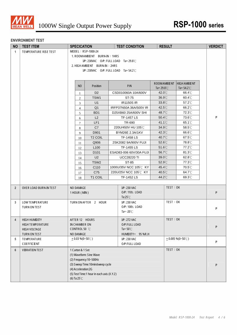
1 TEMPERATURE RISE TEST MODEL:RSP-1000-24 1. ROOM AMBIENT BURN-IN:1HRS I/P: 230VAC O/P: FULL LOAD Ta= 29.8
2. HIGH AMBIENT BURN-IN:2HRS I/P: 230VAC O/P: FULL LOAD Ta= 54.2
NO Position P/N ROOM AMBIENT
Ta= 29.8 HIGH AMBIENT
Ta= 54.2 1 D2 CSD010060A 10A/600V 42.0 66.4
2 TSW1 ST-75 36.9 60.4
3 U1 IR1150S IR 33.8 57.2
4 Q1 IRFP37N50A 36A/500V IR 42.5 66.2
5 BD1 D25XB60 25A/600V SHI 48.7 72.3
6 L2 TF-1457 LS 50.4 73.6
7 LF1 TR-690 41.1 65.1
8 C7 220U/450V HU 105 34.9 58.5
9 D901 BYM26E 2.3A/1KV 42.3 66.6
10 T2 COIL TF-1458 LS 40.7 67.5
11 Q906 2SK2082 9A/900V FUJI 52.6 78.8
12 L100 TF-1455 LS 51.6 77.2
13 D101 ESAD83-006 60V/30A FUJI 56.7 81.3
14 U2 UCC28220 TI 39.0 62.8
15 TSW2 ST-85 52.9 77.3
16 C110 1000U/35V NCC 105 KY 45.4 70.5
17 C75 220U/25V NCC 105 KY 40.5 64.7
18 T1 COIL TF-1452 LS 44.2 69.3
P
2 OVER LOAD BURN-IN TEST NO DAMAGE 1 HOUR ( MIN )
I/P: 230 VAC O/P: 110﹪LOAD Ta:25
TEST:OK P
3 LOW TEMPERATURE TURN ON TEST
TURN ON AFTER 2 HOUR
I/P: 230 VAC O/P: 100﹪LOAD Ta= -20
TEST:OK
P
4 HIGH HUMIDITY HIGH TEMPERATURE HIGH VOLTAGE TURN ON TEST
AFTER 12 HOURS IN CHAMBER ON CONTROL 50 NO DAMAGE
I/P: 272 VAC O/P:FULL LOAD Ta= 50 HUMIDITY= 95 %R.H
TEST:OK
P
5 TEMPERATURE COEFFICIENT
+ 0.03 %(0~50) I/P: 230 VAC O/P:FULL LOAD
+ 0.005 %(0~50) P
6 VIBRATION TEST 1 Carton & 1 Set (1) Waveform: Sine Wave (2) Frequency:10~500Hz (3) Sweep Time:10min/sweep cycle (4) Acceleration:2G (5) Test Time:1 hour in each axis (X.Y.Z) (6) Ta:25
TEST:OK
P

1000W Single Output Power Supply RSP-1000 series
Model: RSP-1000-24 Test Report 5 / 6
SAFETY TEST NO TEST ITEM SPECICATION TEST CONDITION RESULT VERDICT
I/P-O/P: 9.89 mA I/P-FG: 8.1 mA
O/P-FG: 7.02 mA
1 WITHSTAND VOLTAGE I/P-O/P: 3 KVAC/min I/P-FG: 1.5 KVAC/min O/P-FG: 0.5 KVAC/min
I/P-O/P: 3.6 KVAC/min I/P-FG: 1.8 KVAC/min O/P-FG: 0.6 KVAC/min Ta:25 NO DAMAGE
P
I/P-O/P: 10 GΩ
I/P-FG: 9 MΩ O/P-FG: 2 MΩ
2 ISOLATION RESISTANCE I/P-O/P:500VDC>100MΩ I/P-FG: 500VDC>100MΩ O/P-FG:500VDC>100MΩ
I/P-O/P: 500 VDC I/P-FG: 500 VDC O/P-FG: 500 VDC Ta:25
NO DAMAGE
P
3 GROUNDING CONTINUITY FG(PE) TO CHASSIS OR TRACE < 100 mΩ
40 A / 2min Ta:25
17 mΩ P
4 APPROVAL TUV: Certificate NO :R50094068 UL: File NO :R50094068 P
E.M.C TEST
NO TEST ITEM SPECICATION TEST CONDITION RESULT VERDICT 1 HARMONIC EN61000-3-2
CLASS D I/P: 230 VAC/50HZ O/P:FULL LOAD Ta:25
PASS P
2 CONDUCTION EN55022 CLASS B
I/P: 230 VAC (50HZ) O/P:FULL/50% LOAD Ta:25
PASS Test by certified Lab P
3 RADIATION EN55022 CLASS B
I/P: 230 VAC (50HZ) O/P:FULL LOAD Ta:25
PASS Test by certified Lab P
4 E.S.D EN61000-4-2 INDUSTRY AIR:8KV / Contact:4KV
I/P: 230 VAC/50HZ O/P:FULL LOAD Ta:25
CRITERIA A
P
5 E.F.T EN61000-4-4 INDUSTRY INPUT: 2KV
I/P: 230 VAC/50HZ O/P:FULL LOAD Ta:25
CRITERIA A
P
6 SURGE IEC61000-4-5 INDUSTRY L-N :2KV L,N-PE:4KV
I/P: 230 VAC/50HZ O/P:FULL LOAD Ta:25
CRITERIA A
P
7 Test by certified Lab & Test Report Prepare
M.T.B.F & LIFE CYCLE CALCULATION NO TEST ITEM SPECICATION TEST CONDITION RESULT VERDICT
1 CAPACITOR LIFE CYCLE
RSP-1000-24 : SUPPOSE C110 IS THE MOST CRITICAL COMPONENT I/P: 230VAC O/P:FULL LOAD Ta= 25 LIFE TIME= 1025344 HRS I/P: 230VAC O/P:FULL LOAD Ta= 50 LIFE TIME= 172662 HRS
P
2 MTBF MIL-HDBK-217F NOTICES2 PARTS COUNT TOTAL FAILURE RATE: 35K HRS
P

1000W Single Output Power Supply RSP-1000 series
Model: RSP-1000-24 Test Report 6 / 6
COMPONENT STRESS TEST
NO TEST ITEM SPECICATION TEST CONDITION RESULT VERDICT (1) 870 V 1 Power Transistor
( D to S) or (C to E) Peak Voltage Q900 Rated 2SK2082 : 900 V 9A
I/P:High-Line +3V = 267 V O/P: (1)Full Load Turn on (2) Output Short Ta:25
(2) 830 V P
(1) 83.5 V 2 Diode Peak Voltage D102 Rated S30JC10 : 100V 30A
I/P:High-Line +3V = 267 V O/P: (1)Full Load Turn on (2)Output Short Ta:25
(2) 46 V P
3 Clamp Diode Peak Voltage D900 Rated BYM26E : 1KV 2.3 A
I/P:High-Line +3V = 267 V O/P: (1) Dynamic Load 90%Duty/1KHz Ta:25
(1) 830 V
P
(1) 404 V
(2) 396 V
4 Input Capacitor Voltage C5 Rated : 220u / 450V/ 105
I/P:High-Line +3V = 267 V O/P: (1)Full Load Turn on /Off (2) Min load Turn on /Off
(3)Full Load /Min load Change Ta:25
(3) 404 V
P
(1) 14 V (2) 14 V
5 Control IC Voltage Test U2 Rated UCC28220D : 15 V
I/P:High-Line +3V = 267 V O/P: (1)Full Load Turn on /Off (2) Min load Turn on /Off
(3)Full Load /Min load Change Ta:25
(3) 14 V P
DATE SAMPLE TEST RESULT TESTER APPROVAL
2006/8/4 RD SAMPLE PASS VINCENT TSENG MAX LIN
2006/11/20 PRODUCT SAMPLE W0609A18 PASS VINCENT TSENG MAX LIN
2007/1/5 PRODUCT SAMPLE W0612A26 PASS VINCENT TSENG MAX LIN
2003/12/12 A50-F023