Embed Size (px)
Citation preview

Distributed Antennas:The Concept of Virtual Antenna Arrays
Mischa Dohler of France Telecom R & Dand
A. Hamid Aghvami of King’s College
Presented by Matthew PughAugust 18, 2009
Page 1
Outline
• Basic Idea: Cooperation
• Combining Great Ideas: Relays and MIMO
• Network Topologies and Application to Existing Architectures
• MIMO Capacity
– Ergodic Capacity– Orthogonal MIMO Channel Capacity
• Resource Allocation
Page 2
Basic Idea
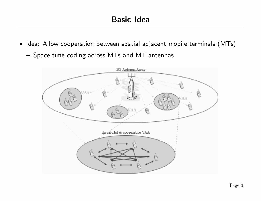
• Idea: Allow cooperation between spatial adjacent mobile terminals (MTs)
– Space-time coding across MTs and MT antennas
Page 3
Motivation: Relay Channels
• Practical Importance: MT relay to other MTs on service boundary
• Theoretical Motivation: information theoretic formulation by Cover and ElGamal
• Simple Proposed Protocols:
– Senonaris: MTs broadcast to BS, adjacent MTs retransmit to BS– Wornell: Similar but with decode-and-forward and amplify-and-forward
• Laneman: cooperation yields full spatial diversity Scaling Laws:
– Gupta & Kumar: per MT capacity decreases with number of users in fixed(although could be random) topology
– Grossglauser & Tse: Mobility counter-acts decrease in per MT capacity∗ hand off information to MTs that are passing by
Page 4

Motivation: MIMO Systems
• Telatar: Capacity gains with additional antennas
• Alamouti: Space-time codes to achieve full transmit diversity
• Tarokh: Generalized theory of space-time codes
• MIMO Relaying results of Gupta & Kumar:
– Considered general topology allowing MTs to communicate to whomeveris needed to maximize the system capacity
– Characterized achievable rate region of the network∗ Requires sophisticated multi-user coding schemes to achieve∗ How achieve in real systems?
Page 5
Virtual Antenna Array Relaying Topology
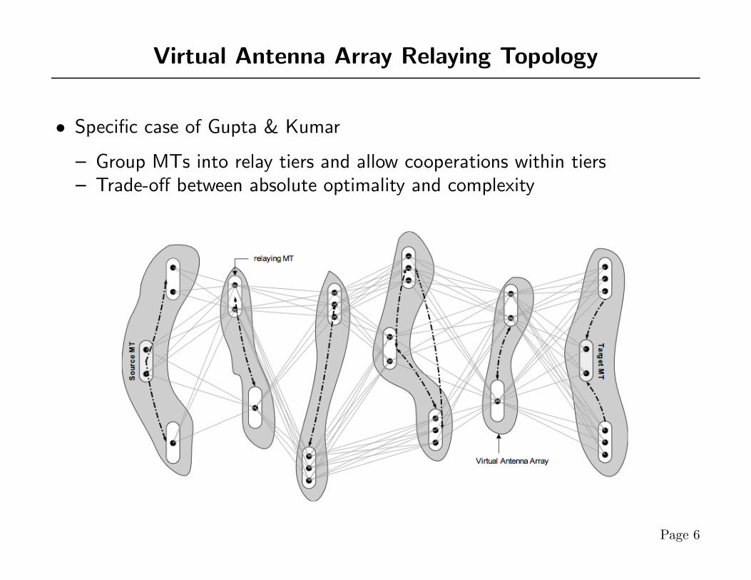
• Specific case of Gupta & Kumar
– Group MTs into relay tiers and allow cooperations within tiers– Trade-off between absolute optimality and complexity
Page 6
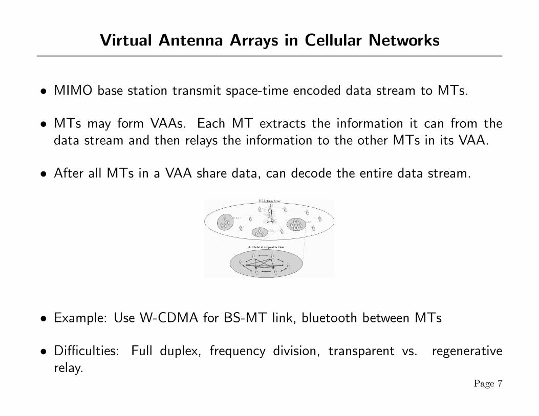
Virtual Antenna Arrays in Cellular Networks
• MIMO base station transmit space-time encoded data stream to MTs.
• MTs may form VAAs. Each MT extracts the information it can from thedata stream and then relays the information to the other MTs in its VAA.
• After all MTs in a VAA share data, can decode the entire data stream.
• Example: Use W-CDMA for BS-MT link, bluetooth between MTs
• Difficulties: Full duplex, frequency division, transparent vs. regenerativerelay.
Page 7
Virtual Antenna Arrays in other Networks
• WLAN
– Issues at coverage edges and possible interference between access points.– Rarely power issues.– WLAN protocol to access point; blue tooth or UWB between devices.– HiperLAN2: direct communication between terminals
• Ad Hoc Networks
– No QoS. Trade-off capacity for latency, jitter, and overhead– Robustness
• Sensor Networks
– Severely power limited– VAAs may save on transmit power, but more reception/processing power
is required.
Page 8
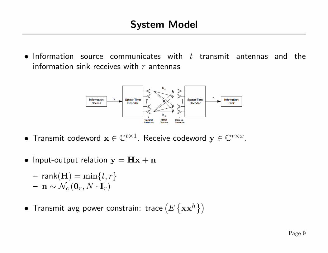
System Model
• Information source communicates with t transmit antennas and theinformation sink receives with r antennas
• Transmit codeword x ∈ Ct×1. Receive codeword y ∈ Cr×x.
• Input-output relation y = Hx + n
– rank(H) = min{t, r}– n ∼ Nc (0r, N · Ir)
• Transmit avg power constrain: trace(E{xxh
})Page 9

Ergodic MIMO Capacity
• Telatar’s result for uncorrelated Rayleigh fading
– Apply to VAA ⇒ distances between MTs in cluster small compared todistances between clusters
C =∫ ∞
0
m log2
(1 +
λ
t
S
N
)·
1m
m−1∑k=0
k!(k + n−m)!
[Ln−mk (λ)
]2λn−me−λ · dλ
λ = unordered eigenvalues of the associated Wishart matrix, m , min{r, t},n , max{r, t}, and Ln−mk (λ) is the Laguerre polynomal of order k.
• Asymptotic Capacity (d , n−m)
C → m log2
(1t
S
N
)+
1log(2)
m−1∑µ=1
m− µd+ µ
+m
d∑µ=1
1µ
− C
Page 10

Orthogonal MIMO Channels
• Orthogonal space-time block codes orthogonalize the MIMO channel intoparallel SISO channels.
– Can optimize over simplified structure
• Space-time block code structure
– Encoder receivers symbols x1, xx, . . . , xs which are part of a longercodeword x.
– Space-time encoder uses a matrix G ∈ Cd×t where d is the number ofsymbol durations required to transmit the space-time codeword and t isthe number of (distributed) transmit elements.
– Transmission rate R , sd
• Note: space-time codes improve diversity, but do not provide coding gains.
Page 11
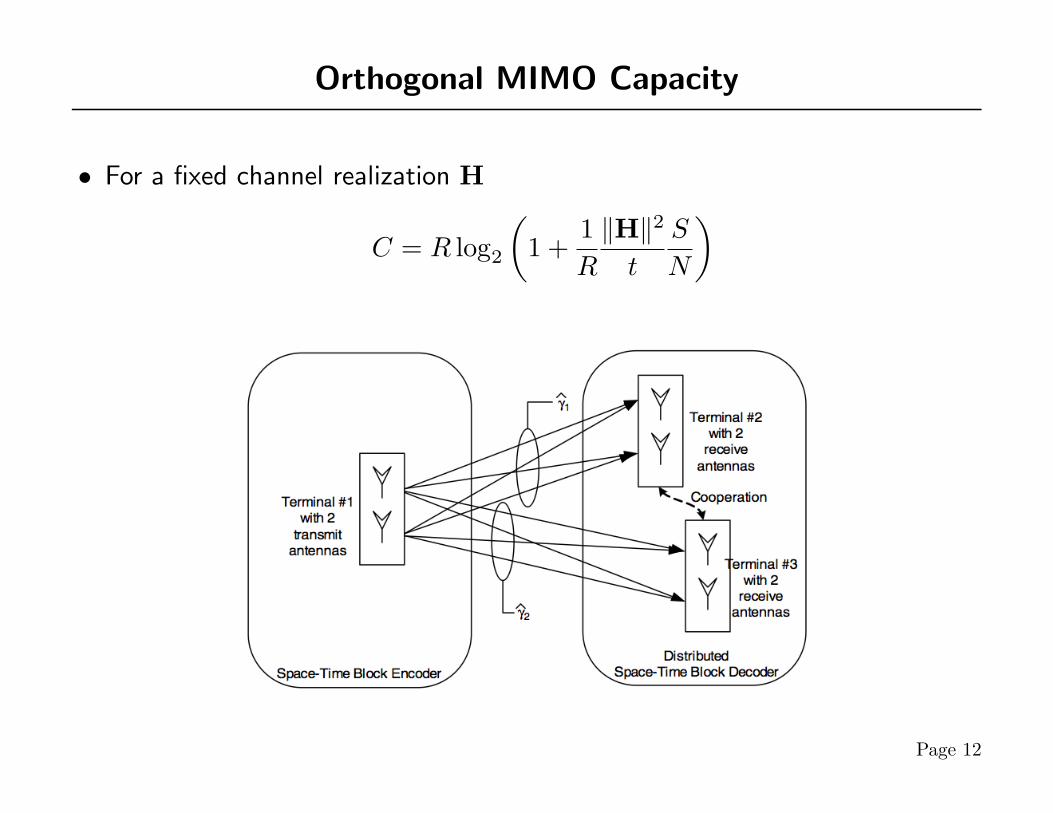
Orthogonal MIMO Capacity
• For a fixed channel realization H
C = R log2
(1 +
1R
‖H‖2
t
S
N
)
Page 12
System Model
• Source MT (s-MT) wants to transmit to target MT (t-MT)
• Spatially adjacent relaying MT (r-MT) are grouped into VAAs.
– Optimization of topology not considered– MTs can have arbitrary number of antennas
• Cost of architecture: complexity. Ignoring relaying power and bandwidth.
• Intra-VAA communication assumed error free.
• Orthogonal Relaying: resources partitioned such that no interference betweenrelaying stages
• Non-Orthogonal Relaying: resource reuse, but interference between stages
• Average channel conditions of all links assumed to be known at all nodes
Page 13
Resource Allocation Protocols
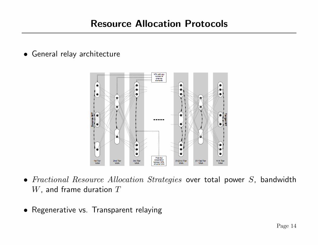
• General relay architecture
• Fractional Resource Allocation Strategies over total power S, bandwidthW , and frame duration T
• Regenerative vs. Transparent relaying
Page 14

End-to-End Throughput
• In relaying architecture, capacity limited by the weakest link.
– Strength of MIMO channel measured by # of receive antenna– Generally desirable to have cooperation so all virtual MIMO clusters have
the same # of receive antenna
C = supα,β {min {C1(α1, β1, λ1, γ1), . . . , CK(αK, βK, λK, γK)}}
Cv = αv · Eλv{mv log2
(1 + λv
γvtv
βvαv
SN
)}Page 15
Optimal Resource Allocation
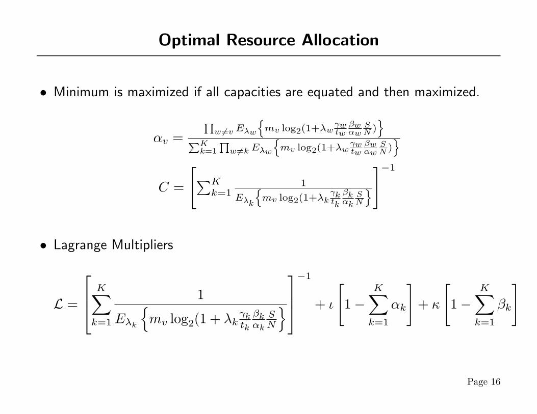
• Minimum is maximized if all capacities are equated and then maximized.
αv =Qw 6=v Eλw
nmv log2(1+λw
γwtw
βwαw
SN )
oPKk=1
Qw 6=kEλw
nmv log2(1+λw
γwtw
βwαw
SN )
o
C =
[∑Kk=1
1
Eλk
nmv log2(1+λk
γktk
βkαk
SN
o]−1
• Lagrange Multipliers
L =
K∑k=1
1
Eλk
{mv log2(1 + λk
γktk
βkαk
SN
}−1
+ ι
[1−
K∑k=1
αk
]+ κ
[1−
K∑k=1
βk
]
Page 16

Resource Allocation Strategies
• Near-optimal fractional bandwidth and fractional power allocation
K∑k=1
βkαk≈ K
• Equal fractional bandwidth but optimized fractional power allocation
αv =1K
• Equal fractional bandwidth and power allocation
– Select minimum of Cv
Cv =1KEλv
{mv log2(1 + λv
γvtv
S
N
}Page 17
Conclusions
• MIMO + Relay = Virtual Antenna Arrays
• Applications to existing domains
• Review of MIMO capacity
• Resource allocation in a relay network
Thank You for Listening
Page 18


![Design of antennas and antenna arrays [ D12 ] - ETH Z](https://img.dokumen.tips/doc/110x75/589ecee61a28ab244d8b5400/design-of-antennas-and-antenna-arrays-d12-eth-z.jpg)

