Embed Size (px)
Citation preview
Structures xxx (2016) xxx–xxx
ISTRUC-00112; No of Pages 11
Contents lists available at ScienceDirect
Structures
j ourna l homepage: www.e lsev ie r .com/ locate /s t ructures
Distortional Influence of Pallet Rack Uprights Subject to Combined Compressionand Bending
J. Bonada ⁎, M.M. Pastor, F. Roure, M. CasafontStrength of Materials and Structural Engineering Department, ETSEIB, UPC, Spain
⁎ Corresponding author.E-mail addresses: [email protected] (J. Bonada), m
(M.M. Pastor), [email protected] (F. Roure), miquel(M. Casafont).
http://dx.doi.org/10.1016/j.istruc.2016.05.0072352-0124/© 2016 The Institution of Structural Engineers
Please cite this article as: Bonada J, et al, Disto(2016), http://dx.doi.org/10.1016/j.istruc.20
a b s t r a c t
a r t i c l e i n f oArticle history:Received 27 January 2016Received in revised form 12 April 2016Accepted 21 May 2016Available online xxxx
A pallet rack is a structure in which the beams and uprights are cold-formed steel sections. The beam-uprightconnections are normally clipped in order to select the beam levels required and for ease of assembly. For thisreason, the uprights contain holes and perforations distributed along their length. The complexity of thesecomponents,with local, distortional and torsional/flexural buckling behaviour, represents a challenge in structur-al design. The loads acting on the structure are induced by the weight of pallets to be stored, and transmitted tothe uprights by the semi-rigid connection system. Therefore, the uprights are thin-walled singly symmetricalperforated open cross-sections bearing axial load and bending moment simultaneously. The main objective ofthis paper is to analyse the influence of the bendingmoment on the load bearing capacity of rack uprights subjectto axial load together with bending moment. Bending is induced by means of axial forces eccentrically applied.The influence of bending on the strength capacity of rack uprights is analysed through finite element analysis,where residual stresses and strength enhancement induced during cold forming of sections are also considered.Experimental tests have been performed reproducing the load conditions in order to validate the FEA results. Theultimate load has also been calculated according to the European Standards and compared to experimentalresults.
© 2016 The Institution of Structural Engineers. Published by Elsevier Ltd. All rights reserved.
Keywords:Rack uprightsCombined compression and bendingFE analysisExperimental testing
1. Introduction
The main components of a steel storage pallet are the uprights, thepallet beams and the diagonals. The uprights are usually subjected toaxial load and bending moment. The loads carried by the pallet beamsare transmitted to the uprights through semi-rigid connections. Whenthe loads are symmetrically distributed, at both sides of an upright,then it is working in pure compression. Whereas when the loadingscheme is asymmetric, then the upright is subjected to compressionand bending. The case of pure axial load is extremely rare in rack designpractice and it is generally associated with the verification of lacings.With reference to the uprights, in addition to the contribution due toaxial load, it is of fundamental importance to take into account alsothe presence of bending moments along the principal axes of thecross-section [1].
Extensive research has been focused onmembers loaded under purecompression; among these, [2,3] that are devoted to experimental test-ing of compressed members. Three methods (analytical, experimentaland FEA) to estimate the effective area and the position of the centre
[email protected]@upc.edu
. Published by Elsevier Ltd. All rights
rtional Influence of Pallet Rac16.05.007
of gravity for perforated sections are presented in [2]. Experimentaldeformationsweremeasured on specimen lengths prone to distortionalbuckling failure in order to analyse the interaction between distortionaland global buckling modes [3].
However, little research has been done to date about the behaviourof uprights subjected to combined compression and bending. Millerand Pekoz [4] investigated the behaviour of cold-formed steel lipped-channel columns with rectangular perforation patterns eccentricallyloaded, and code predictions were compared with empirical responses.The results from an experimental investigation and a finite elementanalysis of cold-formed channel columns with inclined simple edgestiffeners subjected to eccentric loads presented by Zhang et al. in [5],show that loading position affects the load carrying capacity and failuremode of specimens. Mohri et al. [6] investigated bi-symmetric cross-sections under combined bending and axial forces and compared anon-linear model for the stability analysis to non-linear finite elementresults. An experimental campaign [7] is conducted on the behaviourof cold-formed steel lipped-channel beam-columns under bi-axialbending and compression to characterize the failure modes and themember capacity, and the results are used to verify the reliability ofcode predictions about the strength of beam-columns.
Concerning racks, Davies et al. [8] compared both GBT (with treat-ment of perforations) and FEA for predicting the failure load of perforat-ed cold-formed steel sections subject to axial load and bendingwith test
reserved.
k Uprights Subject to Combined Compression and Bending, Structures

Fig. 1. Main dimensions of the analysed rack upright.
2 J. Bonada et al. / Structures xxx (2016) xxx–xxx
results. Crisan et al. [9] carried out a testing programme including bend-ing about minor axis of single uprights with web in compression andtension, according to Annex A.2.9 [10]. Bernuzzi and Simoncelli [11]analysed the interaction between axial loads and bending moments inrack uprights, therefore three European design approaches were com-pared to evaluate the beam-column capacity.
The purpose of this paper is to investigate eccentrically compressedrack members in order to reproduce compression and uniform bendingload case and analyse the influence of distortional buckling in theupright. Uniform axial bending and compression were reproduced bymeans of a loading set-up specifically designed to apply eccentric axialloads. Experimental tests are performed on 700 mm upright lengthwith eccentricities defined on the non-symmetrical axis of the cross-section. Two different methodologies to obtain the load carrying capac-ity of the upright by FEA are presented and compared to experimentalresults. Finally, the failure load is also obtained through the EuropeanStandards in order to analyse its agreement with experimentalmeasurements.
2. Experimental tests
2.1. Analysed cross-section and material testing
The analysed rack upright (steel grade S355) is shown in Fig. 1. It is acommercial open cold-formed steel section, whose main dimensionsare: web width of 80 mm, flange height of 69 mm, 1.8 mm of thicknessand 4.4mm of corner radii. The holes are located at themiddle positionof flange parts.
Most of rack sections are manufactured by cold-roll forming. As aconsequence, the mechanical properties of the material may be differ-ent from the virgin sheet coil. Therefore, several tensile coupons werecut out from flat and corner areas of the upright in order to determinate
Fig. 2. Flat and corner zones were tensile coupons were cut out.
Please cite this article as: Bonada J, et al, Distortional Influence of Pallet Rac(2016), http://dx.doi.org/10.1016/j.istruc.2016.05.007
their stress–strain behaviour. Flat coupons were cut out from the onlypart of the flange without any perforation. All corners radii of thecross-section have the same value, thus the enhancement of itsmechanical properties was evaluate though coupons obtained fromcorner area shown in Fig. 2.
Table 1 shows the values of yield and ultimate strength obtainedfrom the tensile tests following the recommendations of EN100002-1European Standard. It can be observed that the yield and ultimatestrength in corner areas are 17.5% and 7.7% higher than in flat areasdue to strain hardening, respectively. Moreover, the engineeringstress–strain curves for all tensile coupons are plotted in Fig. 3. It canbe observed the enhancement of the yield stress and ultimate stress ofcorner coupons as a consequence of strain hardening. On the otherhand the ductility has decreased.
2.2. Experimental set-up
Several experimental tests have been done to determine the loadcarrying capacity of the rack upright subject to a combined compressionand bending. Bending is induced by means of axial forces eccentricallyapplied. At each end of the rack upright a plate made of 30 mm thicksteel is used to restrain the distortion and warping displacement ofthe section (Fig. 4). In order to introduce the eccentric axial force, asecond steel plate of 15mmof thickness is fixed to the first one througha system of slotted holes and bolts, which allows the lateral displace-ment (Z direction) of the longitudinal upright axis from the applicationpoint of the axial force (Fig. 5). In addition, the whole sample has theflexural deformation modes pinned at both ends by means of twosteel balls that fix the load application point (Fig. 6). Finally, a specialdevice avoids the rotation around the longitudinal axis of the specimenby means of guides and cylinders (Figs. 6–7).
The axial load is applied by means of a hydraulic jack, with a loadspeed of 150 N/s and measured by a force transducer. The shortening
Table 1Yield and ultimate strength of flat and corner areas of the rack section.
Sample fy (MPa) fu (MPa)
Flat 1 417 478Flat 2 416 483Flat 3 422 479Flat (Mean) 418 480Corner 1 486 506Corner 2 500 527Corner 3 510 521Corner 4 477 510Corner 5 478 510Corner 6 492 530Corner (Mean) 491 (Δ17.5%) 517 (Δ7.7%)
k Uprights Subject to Combined Compression and Bending, Structures
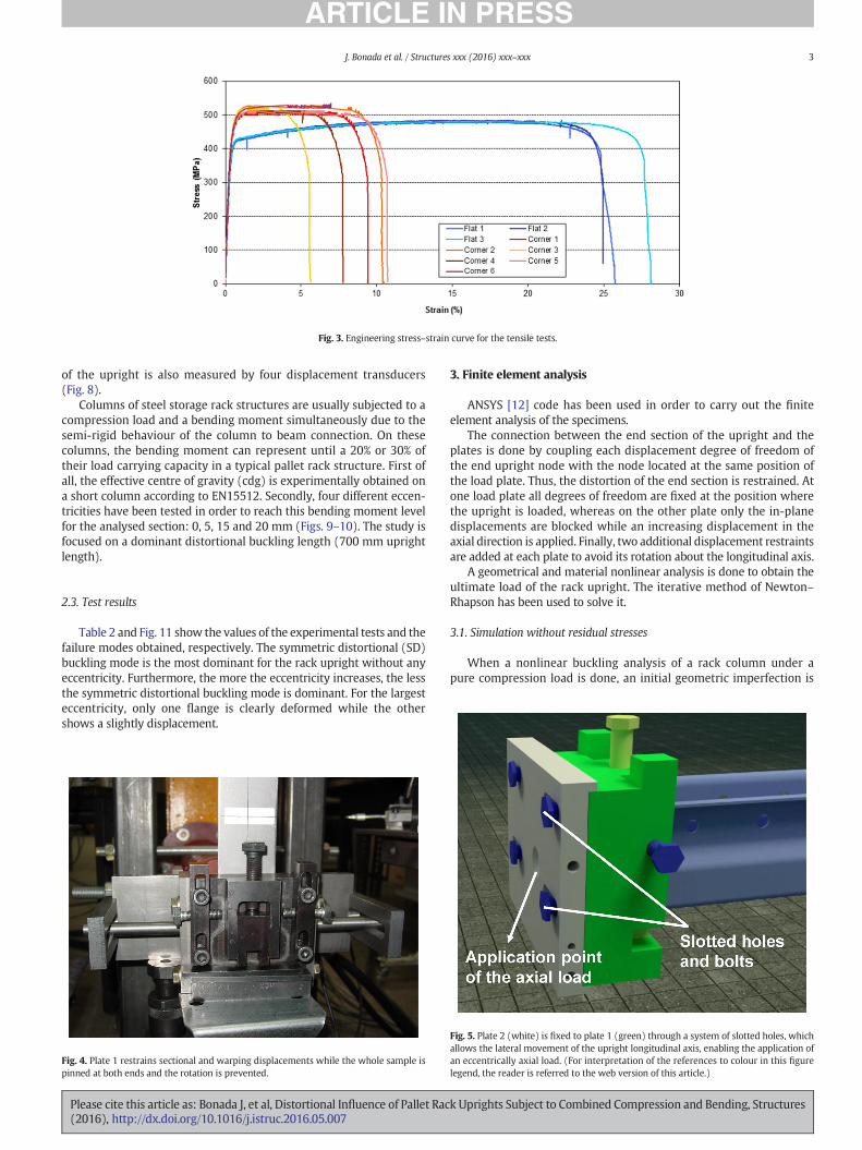
Fig. 3. Engineering stress–strain curve for the tensile tests.
3J. Bonada et al. / Structures xxx (2016) xxx–xxx
of the upright is also measured by four displacement transducers(Fig. 8).
Columns of steel storage rack structures are usually subjected to acompression load and a bending moment simultaneously due to thesemi-rigid behaviour of the column to beam connection. On thesecolumns, the bending moment can represent until a 20% or 30% oftheir load carrying capacity in a typical pallet rack structure. First ofall, the effective centre of gravity (cdg) is experimentally obtained ona short column according to EN15512. Secondly, four different eccen-tricities have been tested in order to reach this bending moment levelfor the analysed section: 0, 5, 15 and 20 mm (Figs. 9–10). The study isfocused on a dominant distortional buckling length (700 mm uprightlength).
2.3. Test results
Table 2 and Fig. 11 show the values of the experimental tests and thefailure modes obtained, respectively. The symmetric distortional (SD)buckling mode is the most dominant for the rack upright without anyeccentricity. Furthermore, the more the eccentricity increases, the lessthe symmetric distortional buckling mode is dominant. For the largesteccentricity, only one flange is clearly deformed while the othershows a slightly displacement.
Fig. 4. Plate 1 restrains sectional and warping displacements while the whole sample ispinned at both ends and the rotation is prevented.
Please cite this article as: Bonada J, et al, Distortional Influence of Pallet Rac(2016), http://dx.doi.org/10.1016/j.istruc.2016.05.007
3. Finite element analysis
ANSYS [12] code has been used in order to carry out the finiteelement analysis of the specimens.
The connection between the end section of the upright and theplates is done by coupling each displacement degree of freedom ofthe end upright node with the node located at the same position ofthe load plate. Thus, the distortion of the end section is restrained. Atone load plate all degrees of freedom are fixed at the position wherethe upright is loaded, whereas on the other plate only the in-planedisplacements are blocked while an increasing displacement in theaxial direction is applied. Finally, two additional displacement restraintsare added at each plate to avoid its rotation about the longitudinal axis.
A geometrical and material nonlinear analysis is done to obtain theultimate load of the rack upright. The iterative method of Newton–Rhapson has been used to solve it.
3.1. Simulation without residual stresses
When a nonlinear buckling analysis of a rack column under apure compression load is done, an initial geometric imperfection is
Fig. 5. Plate 2 (white) is fixed to plate 1 (green) through a system of slotted holes, whichallows the lateral movement of the upright longitudinal axis, enabling the application ofan eccentrically axial load. (For interpretation of the references to colour in this figurelegend, the reader is referred to the web version of this article.)
k Uprights Subject to Combined Compression and Bending, Structures
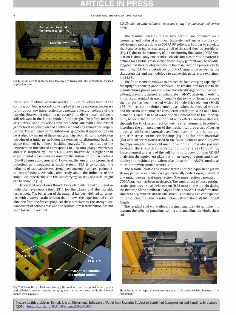
Fig. 6. Set-up used to apply the axial force by a hydraulic jack. The steel balls fix the loadapplication point.
4 J. Bonada et al. / Structures xxx (2016) xxx–xxx
introduced to obtain accurate results [13]. On the other hand, if thecompression load is eccentrically applied it can be no longer necessaryto introduce any imperfection to generate a flexural collapse of theupright. However, it might be necessary if the distortional buckling isstill relevant in the failure mode of the upright. Therefore, for eacheccentricity, two simulations have been done, one with a distortionalgeometrical imperfection and another without any geometrical imper-fection. The influence of the distortional geometrical imperfection canbe studied by means of these analyses. The geometrical imperfectionintroduced as initial perturbation is a symmetrical distortional bucklingshape obtained by a linear buckling analysis. The magnitude of theimperfection introduced corresponds to 1.38 mm (flange width/50)and it is inspired by EN1993-1-5. This magnitude is higher thanexperimental measurements done by the authors of similar sections(0.6–0.85 mm approximately). However, the aim of this geometricalimperfection introduced as initial state in FEA is to consider theinfluence of residual stresses, strength enhancement and real geometri-cal imperfections. An exhaustive study about the influence of theamplitude imperfections on the load carrying capacity of a rack uprightcan be found in [13].
The created model uses 8-node brick elements (Solid 185) and 4-node shell elements (Shell 181) for the plates and the upright,respectively. The behaviour of the material has been defined as isotro-pic, with a stress–strain relation that follows the experimental curveobtained from the flat coupons. For these simulations, the strength en-hancement of corner areas and the residual stress distribution has notbeen taken into account.
Fig. 7. Detail of the steel ball used to apply the axial force and the special device (guidesand cylinders) used to restrain the upright torsion at both ends while the flexuralmodes remain pinned.
Please cite this article as: Bonada J, et al, Distortional Influence of Pallet Rac(2016), http://dx.doi.org/10.1016/j.istruc.2016.05.007
3.2. Simulation with residual stresses and strength enhancement of cornerareas
The residual stresses of the rack section are obtained via ageometric and material nonlinear finite element analysis of the coldroll-forming process done in COPRA RF software. In order to simulatethe manufacturing process only a half of the steel sheet is considered(Fig. 12) due to the symmetry of the roll forming line. Once COPRA sim-ulation is done, only one residual elastic and plastic strain pattern isdefined for a virtual cross-section without any perforation. The residuallongitudinal stresses obtained due to the manufacturing process can beseen in Fig. 13. More details about COPRA simulation as well as thecharacteristics and methodology to define this pattern are explainedin [14,15].
The finite element analysis to predict the load carrying capacity ofthe upright is done in ANSYS software. The residual stresses due to themanufacturing process are considered by introducing the residual strainpattern, previously defined, as initial state in ANSYS analysis. In order tointroduce all residual strain component's due to the roll forming processthe upright has been meshed with a 20-node brick element (SOLID186). Notice that the finite element used when the residual stressesand the strain hardening are considered is different. A 20-node brickelement is used instead of 4-node shell element due to the impossi-bility to correctly reproduce the cold work effects (residual stresses)through the thickness direction with a shell element. In order tointroduce the enhancement of the mechanical properties of cornerareas two different materials have been used to mesh the upright.The true stress–strain relationship (Fig. 14) for both materials(flat and corner regions) used in the finite element model followsthe experimental curves obtained in Section 2.1. It is also possibleto obtain the strength enhancement of corner areas through thefinite element analysis of the roll-forming process done in COPRAanalysing the equivalent plastic strain or curved regions and intro-ducing the residual equivalent plastic strain in ANSYS modes asinitial state with similar results [15].
The residual elastic and plastic strain (not the equivalent plasticstrain) pattern is extended on a geometrically perfect upright, withoutany initial geometrical imperfection (the imperfection generated inCOPRA analysis has been neglected). The equilibrium of these residualstrains produces a small deformation (0.25 mm) on the upright duringthe first step of the nonlinear analysis done in ANSYS. This deformation,similar to a symmetric distortional mode, is obtained as a consequenceof introducing the same residual strain pattern along all the uprightlength.
The residual cold work effects obtained and used do not take intoaccount the effect of punching, coiling and uncoiling the virgin sheetcoil.
Fig. 8. Set-up of the displacement transducers used to obtain the axial displacement of therack upright.
k Uprights Subject to Combined Compression and Bending, Structures
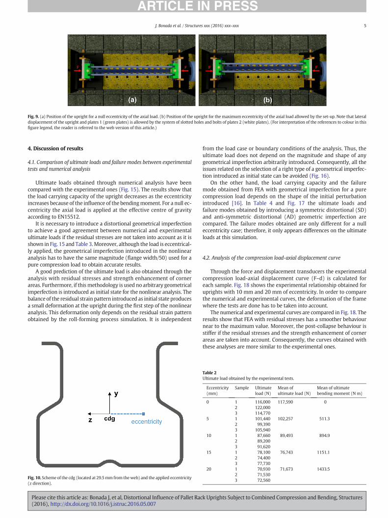
Fig. 9. (a) Position of the upright for a null eccentricity of the axial load. (b) Position of the upright for the maximum eccentricity of the axial load allowed by the set-up. Note that lateraldisplacement of the upright and plates 1 (green plates) is allowed by the system of slotted holes and bolts of plates 2 (white plates). (For interpretation of the references to colour in thisfigure legend, the reader is referred to the web version of this article.)
5J. Bonada et al. / Structures xxx (2016) xxx–xxx
4. Discussion of results
4.1. Comparison of ultimate loads and failure modes between experimentaltests and numerical analysis
Ultimate loads obtained through numerical analysis have beencompared with the experimental ones (Fig. 15). The results show thatthe load carrying capacity of the upright decreases as the eccentricityincreases because of the influence of the bendingmoment. For a null ec-centricity the axial load is applied at the effective centre of gravityaccording to EN15512.
It is necessary to introduce a distortional geometrical imperfectionto achieve a good agreement between numerical and experimentalultimate loads if the residual stresses are not taken into account as it isshown in Fig. 15 and Table 3.Moreover, although the load is eccentrical-ly applied, the geometrical imperfection introduced in the nonlinearanalysis has to have the same magnitude (flange width/50) used for apure compression load to obtain accurate results.
A good prediction of the ultimate load is also obtained through theanalysis with residual stresses and strength enhancement of cornerareas. Furthermore, if thismethodology is used no arbitrary geometricalimperfection is introduced as initial state for the nonlinear analysis. Thebalance of the residual strain pattern introduced as initial state producesa small deformation at the upright during the first step of the nonlinearanalysis. This deformation only depends on the residual strain patternobtained by the roll-forming process simulation. It is independent
Fig. 10. Scheme of the cdg (located at 29.5mm from theweb) and the applied eccentricity(z direction).
Please cite this article as: Bonada J, et al, Distortional Influence of Pallet Rac(2016), http://dx.doi.org/10.1016/j.istruc.2016.05.007
from the load case or boundary conditions of the analysis. Thus, theultimate load does not depend on the magnitude and shape of anygeometrical imperfection arbitrarily introduced. Consequently, all theissues related on the selection of a right type of a geometrical imperfec-tion introduced as initial state can be avoided (Fig. 16).
On the other hand, the load carrying capacity and the failuremode obtained from FEA with geometrical imperfection for a purecompression load depends on the shape of the initial perturbationintroduced [16]. In Table 4 and Fig. 17 the ultimate loads andfailure modes obtained by introducing a symmetric distortional (SD)and anti-symmetric distortional (AD) geometric imperfection arecompared. The failure modes obtained are only different for a nulleccentricity case; therefore, it only appears differences on the ultimateloads at this simulation.
4.2. Analysis of the compression load-axial displacement curve
Through the force and displacement transducers the experimentalcompression load-axial displacement curve (F–d) is calculated foreach sample. Fig. 18 shows the experimental relationship obtained foruprights with 10 mm and 20 mm of eccentricity. In order to comparethe numerical and experimental curves, the deformation of the framewhere the tests are done has to be taken into account.
The numerical and experimental curves are compared in Fig. 18. Theresults show that FEA with residual stresses has a smoother behaviournear to the maximum value. Moreover, the post-collapse behaviour isstiffer if the residual stresses and the strength enhancement of cornerareas are taken into account. Consequently, the curves obtained withthese analyses are more similar to the experimental ones.
Table 2Ultimate load obtained by the experimental tests.
Eccentricity(mm)
Sample Ultimateload (N)
Mean ofultimate load (N)
Mean of ultimatebending moment (N m)
0 1 116,000 117,590 02 122,0003 114,770
5 1 101,440 102,257 511.32 99,3903 105,940
10 1 87,660 89,493 894.92 89,2003 91,620
15 1 78,100 76,743 1151.12 74,4003 77,730
20 1 70,930 71,673 1433.52 71,5303 72,560
k Uprights Subject to Combined Compression and Bending, Structures
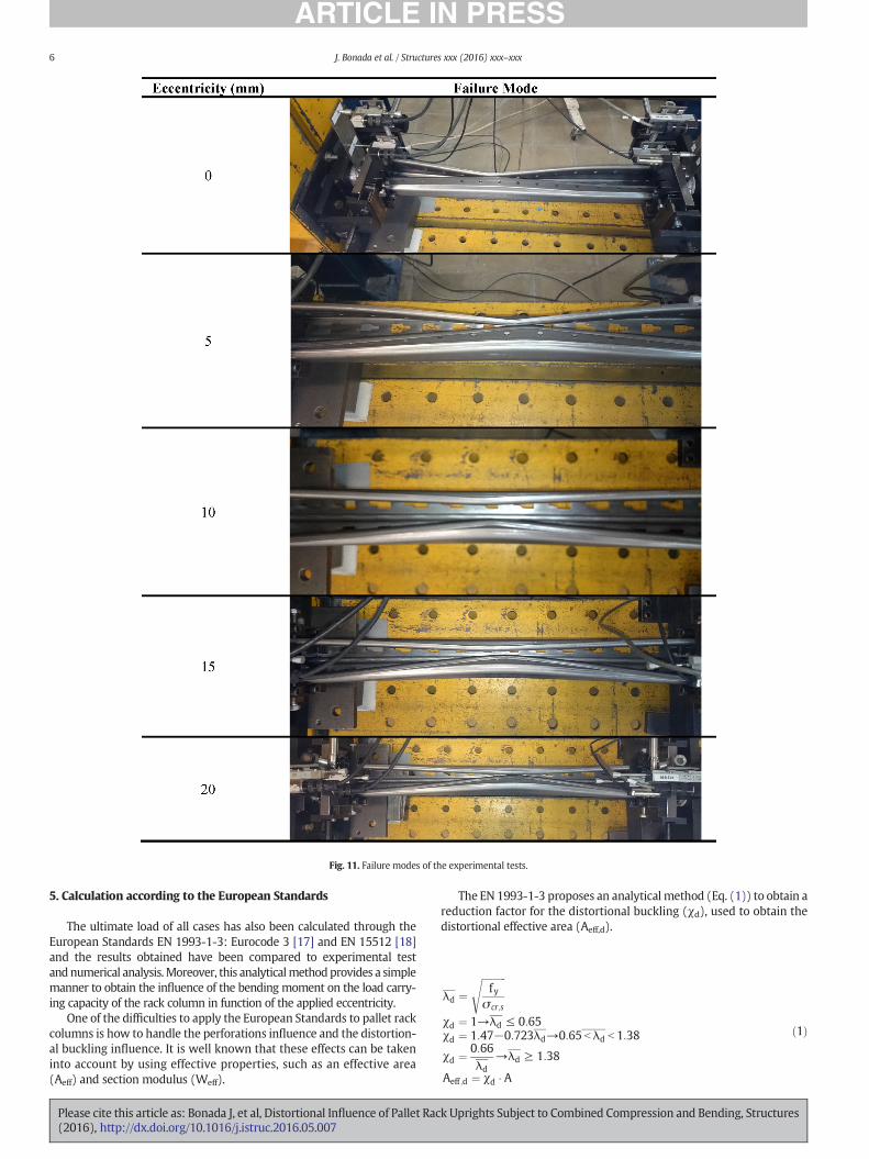
Fig. 11. Failure modes of the experimental tests.
6 J. Bonada et al. / Structures xxx (2016) xxx–xxx
5. Calculation according to the European Standards
The ultimate load of all cases has also been calculated through theEuropean Standards EN 1993-1-3: Eurocode 3 [17] and EN 15512 [18]and the results obtained have been compared to experimental testandnumerical analysis.Moreover, this analyticalmethodprovides a simplemanner to obtain the influence of the bending moment on the load carry-ing capacity of the rack column in function of the applied eccentricity.
One of the difficulties to apply the European Standards to pallet rackcolumns is how to handle the perforations influence and the distortion-al buckling influence. It is well known that these effects can be takeninto account by using effective properties, such as an effective area(Aeff) and section modulus (Weff).
Please cite this article as: Bonada J, et al, Distortional Influence of Pallet Rac(2016), http://dx.doi.org/10.1016/j.istruc.2016.05.007
The EN 1993-1-3 proposes an analytical method (Eq. (1)) to obtain areduction factor for the distortional buckling (χd), used to obtain thedistortional effective area (Aeff,d).
λd ¼ffiffiffiffiffiffiffiffiffiffify
σ cr;s
s
χd ¼ 1→λd ≤ 0:65χd ¼ 1:47−0:723λd→0:65 b λd b 1:38
χd ¼ 0:66λd
→λd ≥ 1:38
Aeff ;d ¼ χd � A
ð1Þ
k Uprights Subject to Combined Compression and Bending, Structures
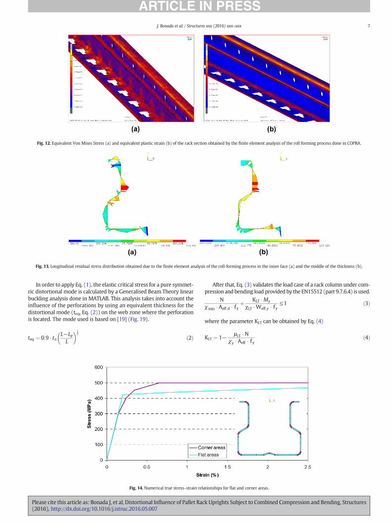
Fig. 12. Equivalent Von Mises Stress (a) and equivalent plastic strain (b) of the rack section obtained by the finite element analysis of the roll forming process done in COPRA.
Fig. 13. Longitudinal residual stress distribution obtained due to the finite element analysis of the roll-forming process in the inner face (a) and the middle of the thickness (b).
7J. Bonada et al. / Structures xxx (2016) xxx–xxx
In order to apply Eq. (1), the elastic critical stress for a pure symmet-ric distortional mode is calculated by a Generalised Beam Theory linearbuckling analysis done in MATLAB. This analysis takes into account theinfluence of the perforations by using an equivalent thickness for thedistortional mode (teq, Eq. (2)) on the web zone where the perforationis located. The mode used is based on [19] (Fig. 19).
teq ¼ 0:9 � tn L−LpL
� �13
ð2Þ
Fig. 14. Numerical true stress–strain rela
Please cite this article as: Bonada J, et al, Distortional Influence of Pallet Rac(2016), http://dx.doi.org/10.1016/j.istruc.2016.05.007
After that, Eq. (3) validates the load case of a rack column under com-pression andbending load providedby the EN15512 (part 9.7.6.4) is used.
Nχmin � Aeff ;d � fy
þ KLT �My
χLT �Weff ;y � fy≤1 ð3Þ
where the parameter KLT can be obtained by Eq. (4)
KLT ¼ 1− μLT � Nχy � Aeff � fy
ð4Þ
tionships for flat and corner areas.
k Uprights Subject to Combined Compression and Bending, Structures

Fig. 15. Influence of the eccentricity in the load carrying capacity of the upright.
Table 3Comparison of the results obtained. GI (analysis with geometrical imperfection), NGI(analysis without geometrical imperfection) and RS (analysis with residual stresses andstrength enhancement).
Eccentricity (mm) FEA ultimate loads (N) FEA/EXP
GI NGI RS GI NGI RS
0 115,283 138,104 117,476 0.98 1.17 1.005 103,827 113,697 101,480 1.02 1.11 0.9910 89,360 96,826 88,132 1.00 1.08 0.9815 79,113 85,010 78,064 1.03 1.11 1.0220 70,556 75,505 70,081 0.98 1.05 0.98
Mean 1.00 1.11 0.99St 0.02 0.04 0.02
Table 4Ultimate loads obtained by introducing a symmetric distortional (SD) or anti-symmetricdistortional (AD) geometric imperfection on the analysis.
Eccentricity (mm)FEA GI ultimate loads (N) FEA/EXP
SD AD SD AD
0 115,283 122,658 0.98 1.045 103,827 103,374 1.02 1.0110 89,360 89,280 1.00 1.0015 79,113 78,431 1.03 1.0220 70,556 70,404 0.98 0.98
Mean 1.00 1.01St 0.02 0.02
8 J. Bonada et al. / Structures xxx (2016) xxx–xxx
For the determination of KLT parameter, the distortional effectivearea (Aeff,d) has been used instead of the local effective area obtain-ed through the experimental stub column test due to its smallervalue.
In these analyses, the bending moment is applied by means of axialforces eccentrically applied, therefore, Eq. (4) can be written to obtainthe maximum axial load that the rack column can carry out (Eq. (5)).
Nχmin � Aeff ;d � fy
þ1− μLT � N
χy � Aeff ;d � fy
!� ecc � N
χLT �Weff;y � fy¼ 1 ð5Þ
where ecc is the applied eccentricity during the experimental test.Table 5 and Fig. 20 show the results of the maximum axial load
obtained by the analytical model provided by the European Standards.
Fig. 16. Failure modes obtained from experimental tests and FEA with residual stres
Please cite this article as: Bonada J, et al, Distortional Influence of Pallet Rac(2016), http://dx.doi.org/10.1016/j.istruc.2016.05.007
It can be observed that the analytical model provides a good agreementwith the experimental test in spite of the difficulties to handle theperforations effect and the distortional influence on the load carryingcapacity of the upright.
Moreover, the contribution of the each effort on the load carryingcapacity of the rack upright has been obtained through Eq. (5), wherethe first term corresponds to the axial load and the second to the bend-ing moment. Table 6 shows that the maximum applied eccentricityproduces a contribution of the bendingmoment around38%, a contribu-tion that could be found in a typical pallet rack structure.
6. Conclusions
A study of the structural behaviour of a rack upright subjected tocombined compression and bending load has been presented. Two
ses and strain hardening for an eccentricity of 0 mm and 20 mm, respectively.
k Uprights Subject to Combined Compression and Bending, Structures
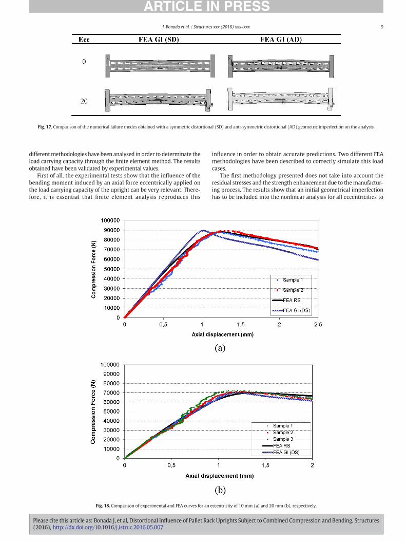
Fig. 17. Comparison of the numerical failure modes obtained with a symmetric distortional (SD) and anti-symmetric distortional (AD) geometric imperfection on the analysis.
9J. Bonada et al. / Structures xxx (2016) xxx–xxx
differentmethodologies have been analysed in order to determinate theload carrying capacity through the finite element method. The resultsobtained have been validated by experimental values.
First of all, the experimental tests show that the influence of thebending moment induced by an axial force eccentrically applied onthe load carrying capacity of the upright can be very relevant. There-fore, it is essential that finite element analysis reproduces this
Fig. 18. Comparison of experimental and FEA curves for an e
Please cite this article as: Bonada J, et al, Distortional Influence of Pallet Rac(2016), http://dx.doi.org/10.1016/j.istruc.2016.05.007
influence in order to obtain accurate predictions. Two different FEAmethodologies have been described to correctly simulate this loadcases.
The first methodology presented does not take into account theresidual stresses and the strength enhancement due to themanufactur-ing process. The results show that an initial geometrical imperfectionhas to be included into the nonlinear analysis for all eccentricities to
ccentricity of 10 mm (a) and 20 mm (b), respectively.
k Uprights Subject to Combined Compression and Bending, Structures
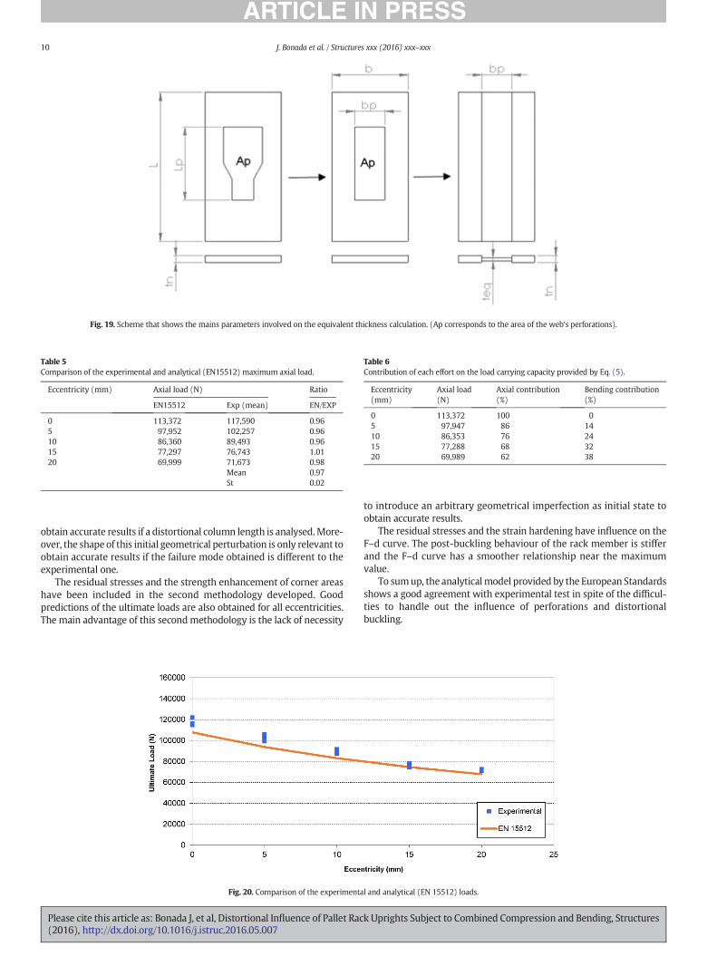
Fig. 19. Scheme that shows the mains parameters involved on the equivalent thickness calculation. (Ap corresponds to the area of the web's perforations).
Table 5Comparison of the experimental and analytical (EN15512) maximum axial load.
Eccentricity (mm) Axial load (N) Ratio
EN15512 Exp (mean) EN/EXP
0 113,372 117,590 0.965 97,952 102,257 0.9610 86,360 89,493 0.9615 77,297 76,743 1.0120 69,999 71,673 0.98
Mean 0.97St 0.02
Table 6Contribution of each effort on the load carrying capacity provided by Eq. (5).
Eccentricity(mm)
Axial load(N)
Axial contribution(%)
Bending contribution(%)
0 113,372 100 05 97,947 86 1410 86,353 76 2415 77,288 68 3220 69,989 62 38
10 J. Bonada et al. / Structures xxx (2016) xxx–xxx
obtain accurate results if a distortional column length is analysed.More-over, the shape of this initial geometrical perturbation is only relevant toobtain accurate results if the failure mode obtained is different to theexperimental one.
The residual stresses and the strength enhancement of corner areashave been included in the second methodology developed. Goodpredictions of the ultimate loads are also obtained for all eccentricities.The main advantage of this secondmethodology is the lack of necessity
Fig. 20. Comparison of the experimenta
Please cite this article as: Bonada J, et al, Distortional Influence of Pallet Rac(2016), http://dx.doi.org/10.1016/j.istruc.2016.05.007
to introduce an arbitrary geometrical imperfection as initial state toobtain accurate results.
The residual stresses and the strain hardening have influence on theF–d curve. The post-buckling behaviour of the rack member is stifferand the F–d curve has a smoother relationship near the maximumvalue.
To sumup, the analyticalmodel provided by the European Standardsshows a good agreement with experimental test in spite of the difficul-ties to handle out the influence of perforations and distortionalbuckling.
l and analytical (EN 15512) loads.
k Uprights Subject to Combined Compression and Bending, Structures
11J. Bonada et al. / Structures xxx (2016) xxx–xxx
References
[1] Bernuzzi C, Gobetti A, Gabbianelli G, Simoncelli M. Unbraced pallet rack design inaccordance with European practice—part2: essential verification checks. Thin-Walled Struct 2015;86:208–29.
[2] Roure F, Pastor MM, Casafont M, Somalo MR. Stub column tests for racking design:experimental testing, FE analysis and EC3. Thin-Walled Struct 2011;49:167–84.
[3] Casafont M, Pastor MM, Roure F, Pekoz T. An experimental investigation of distor-tional buckling of steel storage rack columns. Thin-Walled Struct 2011;49:933–46.
[4] Miller TH, Pekoz T. Load-eccentricity effects on cold-formed steel lipped-channelcolumns. J Struct Eng 1994;120(3):805–23.
[5] Zhang Y, Wang C, Zhang Z. Tests and finite element analysis of pin-ended channelcolumns with inclined simple edge stiffeners. J Constr Steel Res 2007;63(3):383–95.
[6] Mohri F, Bouzerira C, Potier-Ferry M. Lateral buckling of thin-walled beam-columnelements under combined axial and bending loads. Thin-Walled Struct 2008;46(3):290–302.
[7] Torabian S, Zheng B, Schafer BW. Experimental response of cold-formed steel lippedchannel beam-columns. Thin-Walled Struct 2015;86:225–41.
[8] Davies JM, Leach P, Tylor A. The design of perforated cold-formed steel sectionssubject to axial load and bending. Thin-Walled Struct 1997;29(1–4):141–57.
[9] Crisan A, Ungureanu V, Dubina D. Influence of web members on the in-plane andout-of-plane capacities steel storage upright frames. Thin-Walled Struct 2014;81:175–84.
[10] EN15512:2009. Steel static storage systems – adjustable pallet racking systems –principles for structural design. Brussels: CEN; 2009.
Please cite this article as: Bonada J, et al, Distortional Influence of Pallet Rac(2016), http://dx.doi.org/10.1016/j.istruc.2016.05.007
[11] Bernuzzi C, Simoncelli M. European design approaches for isolated cold-formedthin-walled beam-columns with mono-symmetric cross-section. Eng Struct 2015;89:152–68.
[12] ANSYS Mechanical APDL 15.0.[13] Pastor MM, Casafont M, Bonada J, Roure F. Imperfection amplitudes for nonlinear
analysis of open thin-walled steel cross-sections used in rack column uprights.Thin-Walled Struct 2014;76:28–41.
[14] Pastor MM, Bonada J, Roure F, CasafontM. Residual stresses and initial imperfectionsin non-linear analysis. Eng Struct 2013;46:493–507.
[15] Bonada J, Pastor MM, Roure F, Casafont M. Influence of the cold work effects inperforated rack columns under pure compression load. Eng Struct 2015;97:130–9.
[16] Bonada J, Casafont M, Roure F, Pastor MM. Selection of the initial geometrical imper-fection in nonlinear FE analysis of cold-formed steel rack columns. Thin-WalledStruct 2012;51:99–111.
[17] EN 1993-1-3. Eurocode 3 – design of steel structures – part 1–3: general rules— sup-plementary rules far cold-formed members and sheeting; September 2005.
[18] EN 15512. Steel static storage systems – adjustable pallet racking system – principlesfor structural design. European Standard. European Committee for Standardization;March 2009.
[19] Casafont M, Pastor M, Bonada J, Roure F, Peköz T. Linear buckling analysis of perfo-rated steel storage rack columns with the Finite Strip Method. Thin-Walled Struct2012;61:71–85.
k Uprights Subject to Combined Compression and Bending, Structures


![› downloads › brochure › [1].pdfThree standard slotted uprights Hooks Rail & Uprights in Detail Rail The rail is manufactured from anodised aluminium extrusion and supplied in](https://img.dokumen.tips/doc/110x75/5f19fbfe98a0404c693f6302/a-downloads-a-brochure-a-1pdf-three-standard-slotted-uprights-hooks-rail.jpg)