Embed Size (px)
Citation preview
User Manual Please read the Important Notice and Warnings at the end of this document V1.0
www.infineon.com page 1 of 40 2021-03-31
User Manual
Distance2GoL (Software-Controlled FMCW
radar) software user manual
24 GHz-based radar applications
About this document
Scope and purpose
This user manual describes the Distance2GoL firmware, supported algorithms and the development
recommendations required to build low-power applications around Infineon’s Distance2GoL demo kit.
It describes the demonstration firmware applications of the Distance2GoL radar demo board based on the
BGT24LTR11, with details of package architecture and contents.
This document provides guidelines for novice users on how to build and run Distance2GoL radar applications
such as range detection and human tracking, and also to support ease-of-use and faster-to-market integration.
Intended audience
This document is intended for users of the Distance2GoL demo kit who want to get started with Infineon’s
Distance2GoL firmware solution, test several sensing demonstrations, and implement custom radar
applications in the 24 GHz industrial, scientific and medical (ISM) band.
Related documents
Additional information can be found in the supplementary documentation provided with the Distance2GoL kit
in the Infineon Toolbox or from www.infineon.com/24GHz:
• Distance2GoL Application Note (AN615)
• Radar Baseboard XMC4700 Application Note (AN602)

User Manual page 2 of 40 V1.0
2021-03-31
Distance2GoL (Software-Controlled FMCW radar) software user
manual 24 GHz-based radar applications
Table of contents
Table of contents
About this document ....................................................................................................................... 1
Table of contents ............................................................................................................................ 2
List of figures ................................................................................................................................. 3
List of tables .................................................................................................................................. 4
1 Introduction .......................................................................................................................... 5
2 Basic radar concepts ............................................................................................................... 6
2.1 About Doppler radar................................................................................................................................ 6
2.2 About FMCW radar ................................................................................................................................... 7
2.2.1 Target range estimation from FMCW ................................................................................................. 7
2.2.2 Doppler estimation with FMCW ......................................................................................................... 8
3 Hardware overview ............................................................................................................... 10
3.1 Distance2GoL ......................................................................................................................................... 10
3.2 Radar Baseboard XMC4700 ................................................................................................................... 10
3.3 BGT24LTR11 Shield ............................................................................................................................... 12
4 Firmware description ............................................................................................................ 14
4.1 Overview ................................................................................................................................................ 14
4.2 Global architecture................................................................................................................................ 14
4.3 Firmware concept ................................................................................................................................. 16
4.4 Firmware implementation .................................................................................................................... 17
4.5 Raw data acquisition ............................................................................................................................. 18
4.5.1 Chirp generation .............................................................................................................................. 18
4.5.2 Jump offset....................................................................................................................................... 21
4.5.3 Data sampling .................................................................................................................................. 22
4.6 Radar control layer ................................................................................................................................ 24
4.6.1 Radar control APIs ............................................................................................................................ 24
4.6.2 Data store module ............................................................................................................................ 24
4.6.3 Data store and EEPROM management ............................................................................................ 26
4.7 DAVE™ project overview ........................................................................................................................ 27
4.8 Firmware package overview ................................................................................................................. 30
4.9 Footprint ................................................................................................................................................ 30
4.10 Firmware timings .................................................................................................................................. 31
4.11 Firmware customization and configuration......................................................................................... 32
5 1D-tracking algorithm ........................................................................................................... 33
6 RF frequency calibration ........................................................................................................ 34
6.1 Initial boot-up calibration ..................................................................................................................... 34
6.2 Frame-wise frequency check and recalibration ................................................................................... 34
7 Authors ................................................................................................................................ 37
8 References ........................................................................................................................... 38
Revision history............................................................................................................................. 39

User Manual page 3 of 40 V1.0
2021-03-31
Distance2GoL (Software-Controlled FMCW radar) software user
manual 24 GHz-based radar applications
List of figures
List of figures
Figure 1 Doppler effect ...................................................................................................................................... 6
Figure 2 FMCW radar system block diagram .................................................................................................... 7
Figure 3 Basic principle of operation of the FMCW radar system .................................................................... 7
Figure 4 Multiple chirp configuration of FMCW for Doppler estimation .......................................................... 8
Figure 5 Chirp signal with amplitude; frequency as a function of time ........................................................... 9
Figure 6 Single-chirp vs. multi-chirp signal ...................................................................................................... 9
Figure 7 Distance2GoL hardware platform .................................................................................................... 10
Figure 8 Radar Baseboard XMC4700 ............................................................................................................... 11
Figure 9 XMC4700 block diagram .................................................................................................................... 12
Figure 10 BGT24LTR11 Shield board ................................................................................................................ 13
Figure 11 Firmware architecture....................................................................................................................... 14
Figure 12 Firmware flow diagram ..................................................................................................................... 16
Figure 13 Timing flow implementation in firmware ........................................................................................ 17
Figure 14 Raw data acquisition flow diagram .................................................................................................. 18
Figure 15 FMCW chirp generation flow diagram .............................................................................................. 18
Figure 16 All control signals .............................................................................................................................. 20
Figure 17 Chirp generation ................................................................................................................................ 20
Figure 18 Frame structure and terminology .................................................................................................... 21
Figure 19 DAC output/feed signal for tuning voltage filter input .................................................................... 22
Figure 20 Distance2GoL data acquisition and sampling flow.......................................................................... 23
Figure 21 Data store hardware device and algorithm settings structures ...................................................... 24
Figure 22 Interconnection of the data store module with other firmware modules ...................................... 25
Figure 23 EEPROM block diagram ..................................................................................................................... 26
Figure 24 EEPROM structure ............................................................................................................................. 26
Figure 25 ADC DAVE™ app configuration .......................................................................................................... 28
Figure 26 DMA DAVE™ app configuration ......................................................................................................... 29
Figure 27 Package folder structure ................................................................................................................... 30
Figure 28 Raw data acquisition timings ........................................................................................................... 31
Figure 29 Calibration cycle, two frequency measurements ............................................................................ 35
Figure 30 Calibration cycle ................................................................................................................................ 36
User Manual page 4 of 40 V1.0
2021-03-31
Distance2GoL (Software-Controlled FMCW radar) software user
manual 24 GHz-based radar applications
List of tables
List of tables
Table 1 Distance2GoL control and data signals description ........................................................................ 19
Table 2 DAVE™ project apps used .................................................................................................................. 27
Table 3 PWM and GPIO pin configurations .................................................................................................... 28
Table 4 Distance2GoL firmware footprint ..................................................................................................... 31
Table 5 Define statements used for radar firmware configuration .............................................................. 32
User Manual page 5 of 40 V1.0
2021-03-31
Distance2GoL (Software-Controlled FMCW radar) software user
manual 24 GHz-based radar applications
Introduction
1 Introduction
The Distance2GoL (D2GL) radar demo kit is a demonstration platform for Infineon’s silicon-germanium 24 GHz
radar chipset BGT24LTR11. It consists of two boards: the main Radar Baseboard XMC4700 and a radar front-end board BGT24LTR11 Shield.
This document focuses on the demonstration firmware for a Software-Controlled Frequency Modulated
Continuous Wave (SC-FMCW) radar implementation.
The Distance2GoL board is designed to evaluate the capabilities of the BGT24LTR11 IC, comprising one transmit
and one receive channel with the XMC4700 microcontroller utilizing Infineon’s powerful, free-of-charge toolchain
DAVE™ for microcontroller programming.
User Manual page 6 of 40 V1.0
2021-03-31
Distance2GoL (Software-Controlled FMCW radar) software user
manual 24 GHz-based radar applications
Basic radar concepts
2 Basic radar concepts
Below, some basic radar concepts mentioned in this document are explained.
2.1 About Doppler radar
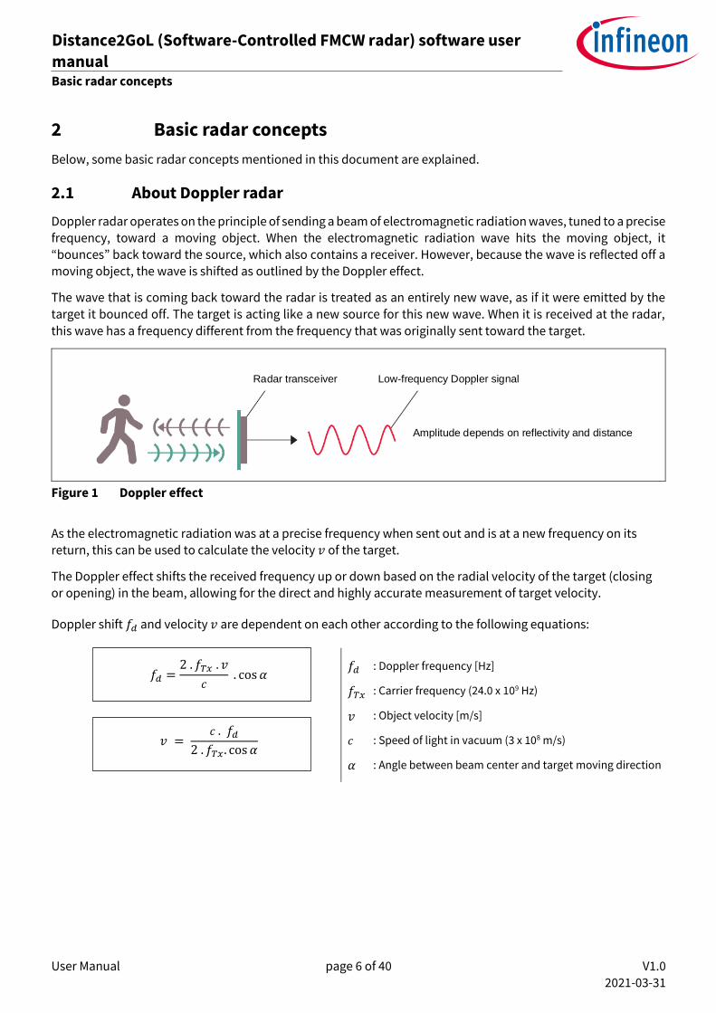
Doppler radar operates on the principle of sending a beam of electromagnetic radiation waves, tuned to a precise frequency, toward a moving object. When the electromagnetic radiation wave hits the moving object, it “bounces” back toward the source, which also contains a receiver. However, because the wave is reflected off a moving object, the wave is shifted as outlined by the Doppler effect.
The wave that is coming back toward the radar is treated as an entirely new wave, as if it were emitted by the
target it bounced off. The target is acting like a new source for this new wave. When it is received at the radar,
this wave has a frequency different from the frequency that was originally sent toward the target.
Radar transceiver Low-frequency Doppler signal
Amplitude depends on reflectivity and distance
Figure 1 Doppler effect
As the electromagnetic radiation was at a precise frequency when sent out and is at a new frequency on its
return, this can be used to calculate the velocity 𝑣 of the target.
The Doppler effect shifts the received frequency up or down based on the radial velocity of the target (closing or opening) in the beam, allowing for the direct and highly accurate measurement of target velocity.
Doppler shift 𝑓𝑑 and velocity 𝑣 are dependent on each other according to the following equations:
𝑓𝑑 =
2 . 𝑓𝑇𝑥 . 𝑣
𝑐 . cos 𝛼
𝑣 = 𝑐 . 𝑓𝑑
2 . 𝑓𝑇𝑥. cos 𝛼
𝑓𝑑
𝑓𝑇𝑥
𝑣
𝑐
𝛼
: Doppler frequency [Hz]
: Carrier frequency (24.0 x 10⁹ Hz)
: Object velocity [m/s]
: Speed of light in vacuum (3 x 10⁸ m/s)
: Angle between beam center and target moving direction

User Manual page 7 of 40 V1.0
2021-03-31
Distance2GoL (Software-Controlled FMCW radar) software user
manual 24 GHz-based radar applications
Basic radar concepts
2.2 About FMCW radar
This diagram is inspired by the start-up guide for EVALBGT60TR24B.
Figure 2 FMCW radar system block diagram
Figure 2 shows the flow of a typical Frequency Modulated Continuous Wave (FMCW) radar system. A frequency modulated transmitted signal is sent through the transmit antenna. The reflected signal from the target is obtained at the receive antenna. This signal is mixed with the transmitted signal at the mixer to obtain the
Intermediate Frequency (IF) output. The IF signal is then digitized at the Analog-to-Digital Converter (ADC) to obtain the data samples of the received output.
2.2.1 Target range estimation from FMCW
Figure 3 shows the basic operation of the FMCW radar system. The transmitted signal is a frequency-modulated
signal. The received signal at the receiver output is obtained after mixing the transmitted signal and the received signal. This generates an IF signal, which can be seen in the figure as a sinusoidal signal. The frequency of the IF signal corresponds to the beat frequency. This beat frequency is used to estimate the range of the target. In case
of multiple targets, the IF signal comprises sinusoids with different frequencies corresponding to the target
ranges.
Figure 3 Basic principle of operation of the FMCW radar system

User Manual page 8 of 40 V1.0
2021-03-31
Distance2GoL (Software-Controlled FMCW radar) software user
manual 24 GHz-based radar applications
Basic radar concepts
Figure 3 shows how to obtain the beat frequency by computing a Fast Fourier Transform (FFT) over the IF signal. The range of the target can be estimated from the beat frequency as follows:
𝑅 = 𝐶 𝑇𝑐 𝑓𝑏
2 𝐵 𝑅
𝐶
𝑇𝑐
𝑓𝑏
𝐵
: Target distance [m]
: Speed of light in vacuum (3 x 10⁸ m/s)
: Up-chirp time [s]
: Beat frequency corresponding to the target [Hz]
: Bandwidth [Hz]
2.2.2 Doppler estimation with FMCW
time
frequency
...
2 3
Tc: Up-Chirp
Standby Time
Down-Chirp
N
PRT: Pulse Repetition Time
Tf: Frame Time
Figure 4 Multiple chirp configuration of FMCW for Doppler estimation
Motion in targets produces changes in the IF signal at the receiver. The frequency of the IF signal remains almost the same; however, the phase of the IF signal shows changes. This change in phase of the IF signal from one chirp to another is related to the radial velocity of the targets, and can be given as:
Δ𝜔 =
4 𝜋𝑣𝑟 𝑇𝑐
𝜆
Δ𝜔
𝑣𝑟
𝑇𝑐
𝜆
: Change in phase [rad]
: Radial velocity of moving target [m/s]
: Chirp duration [s]
: Wavelength [m]
The change of phase can be evaluated over multiple chirps to obtain the velocity of the moving target. This can be accomplished by computing FFT over the chirps.
• Sample – each up-chirp is digitized by an ADC to 12-bit, complex (I/Q) and time-domain raw data stored as 2-byte values. Currently, the maximum capturable number of samples per received chirp is defined by the SAMPLES_PER_CHIRP macro in the config.h header file.
User Manual page 9 of 40 V1.0
2021-03-31
Distance2GoL (Software-Controlled FMCW radar) software user
manual 24 GHz-based radar applications
Basic radar concepts
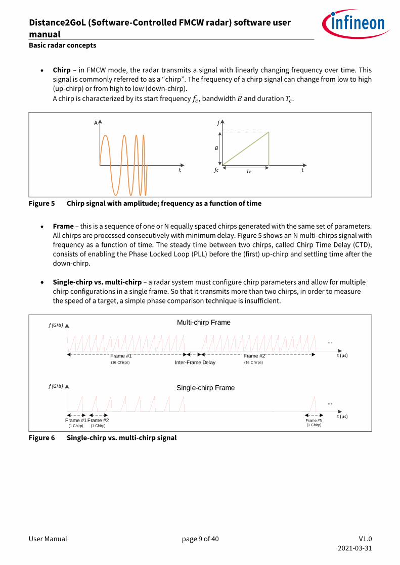
• Chirp – in FMCW mode, the radar transmits a signal with linearly changing frequency over time. This signal is commonly referred to as a “chirp”. The frequency of a chirp signal can change from low to high (up-chirp) or from high to low (down-chirp).
A chirp is characterized by its start frequency 𝑓𝑐, bandwidth 𝐵 and duration 𝑇𝑐.
f
tfc Tc
B
A
t
Figure 5 Chirp signal with amplitude; frequency as a function of time
• Frame – this is a sequence of one or N equally spaced chirps generated with the same set of parameters.
All chirps are processed consecutively with minimum delay. Figure 5 shows an N multi-chirps signal with frequency as a function of time. The steady time between two chirps, called Chirp Time Delay (CTD),
consists of enabling the Phase Locked Loop (PLL) before the (first) up-chirp and settling time after the down-chirp.
• Single-chirp vs. multi-chirp – a radar system must configure chirp parameters and allow for multiple
chirp configurations in a single frame. So that it transmits more than two chirps, in order to measure
the speed of a target, a simple phase comparison technique is insufficient.
f (GHz)
...
t (µs) Frame #1 (16 Chirps) Inter-Frame Delay
Frame #2 (16 Chirps)
f (GHz)
...
t (µs)Frame #1
(1 Chirp)
Frame #2(1 Chirp)
Multi-chirp Frame
Single-chirp Frame
Frame #N
(1 Chirp)
Figure 6 Single-chirp vs. multi-chirp signal
User Manual page 10 of 40 V1.0
2021-03-31
Distance2GoL (Software-Controlled FMCW radar) software user
manual 24 GHz-based radar applications
Hardware overview
3 Hardware overview
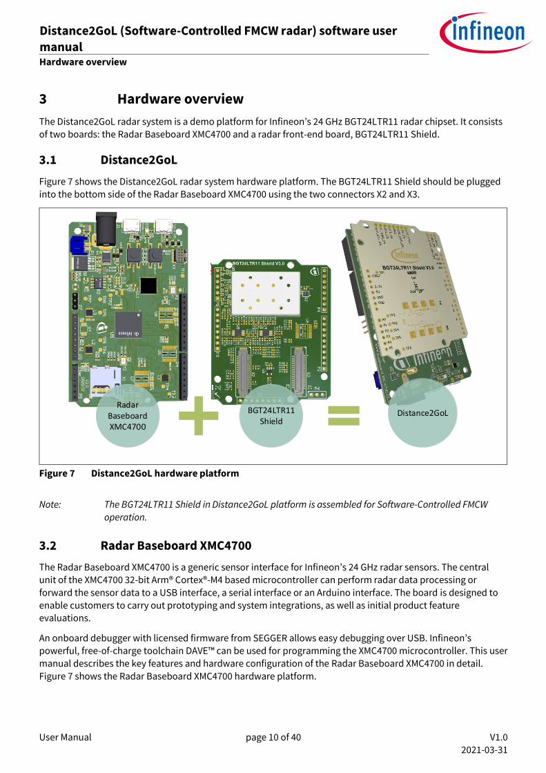
The Distance2GoL radar system is a demo platform for Infineon’s 24 GHz BGT24LTR11 radar chipset. It consists
of two boards: the Radar Baseboard XMC4700 and a radar front-end board, BGT24LTR11 Shield.
3.1 Distance2GoL
Figure 7 shows the Distance2GoL radar system hardware platform. The BGT24LTR11 Shield should be plugged into the bottom side of the Radar Baseboard XMC4700 using the two connectors X2 and X3.
Distance2GoL
Radar Baseboard XMC4700
BGT24LTR11 Shield
Distance2GoL
Figure 7 Distance2GoL hardware platform
Note: The BGT24LTR11 Shield in Distance2GoL platform is assembled for Software-Controlled FMCW
operation.
3.2 Radar Baseboard XMC4700
The Radar Baseboard XMC4700 is a generic sensor interface for Infineon’s 24 GHz radar sensors. The central unit of the XMC4700 32-bit Arm® Cortex®-M4 based microcontroller can perform radar data processing or
forward the sensor data to a USB interface, a serial interface or an Arduino interface. The board is designed to enable customers to carry out prototyping and system integrations, as well as initial product feature evaluations.
An onboard debugger with licensed firmware from SEGGER allows easy debugging over USB. Infineon’s powerful, free-of-charge toolchain DAVE™ can be used for programming the XMC4700 microcontroller. This user manual describes the key features and hardware configuration of the Radar Baseboard XMC4700 in detail.
Figure 7 shows the Radar Baseboard XMC4700 hardware platform.

User Manual page 11 of 40 V1.0
2021-03-31
Distance2GoL (Software-Controlled FMCW radar) software user
manual 24 GHz-based radar applications
Hardware overview
55
mm
85 mm
Arduino-compatible
connectors
Arduino-compatible
connectors
Connectors to
BGT24LTR11
Shield
LDO
LDO
J-K
FlipflopCurrent
sensor
XMC4700 MCUXMC4200
Debugger MCU
Current
sensor
SD
card
reader
Voltage level
translator
Cortex®
Debugger
Connector
XMC Boot Level
Jumper
Current
sensor
Linear Charge
Management
Controller
External Power
Connector
LiPo battery
connector
Figure 8 Radar Baseboard XMC4700
The Radar Baseboard XMC4700 embeds Infineon’s XCM4700, 32-bit Arm® Cortex®-M4 based microcontroller. It can be used to perform radar data processing, configure the board’s peripherals and RF shield management,
and enable radar data communication via a USB or serial interface.
The Distance2GoL firmware is running in the XMC4700 microcontroller and configures the following peripherals:
• Analog-to-Digital Converter (ADC)
• Digital-to-Analog Converter (DAC)
• Direct Memory Access (DMA)
• General-Purpose Input Output (GPIO)
• USIC for I2C serial interface
• CCU8/4 for timer and PWM control signals
• Capture and Compare Unit (CCU)
• Hardware interrupts
• USB interface for host communication
User Manual page 12 of 40 V1.0
2021-03-31
Distance2GoL (Software-Controlled FMCW radar) software user
manual 24 GHz-based radar applications
Hardware overview
Co
nn
ecto
r to Sh
ield
ADC ADC
AD
C
ADC
CCU8
CCU4
USIC
XMC4700
UART
SWDSCK
Debug LED
User LED
User LED
XMC4200 (Debugger)
Micro USB
User LED
Micro USB
USB
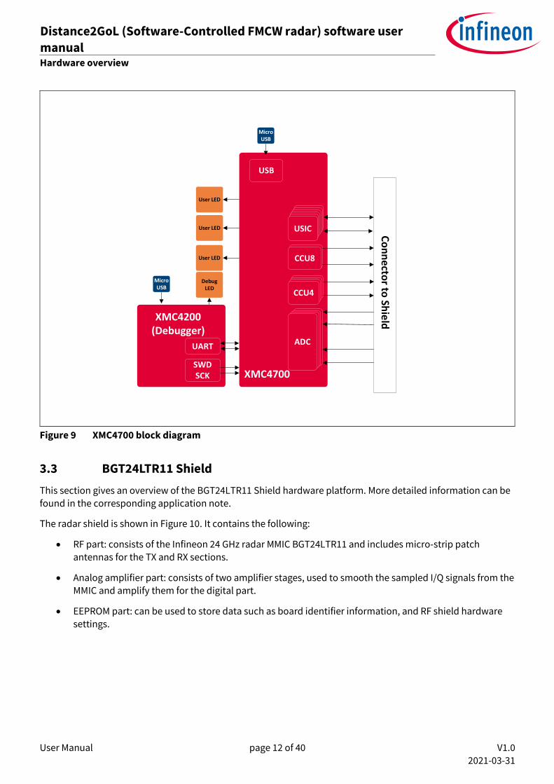
Figure 9 XMC4700 block diagram
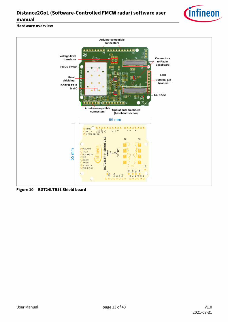
3.3 BGT24LTR11 Shield
This section gives an overview of the BGT24LTR11 Shield hardware platform. More detailed information can be found in the corresponding application note.
The radar shield is shown in Figure 10. It contains the following:
• RF part: consists of the Infineon 24 GHz radar MMIC BGT24LTR11 and includes micro-strip patch antennas for the TX and RX sections.
• Analog amplifier part: consists of two amplifier stages, used to smooth the sampled I/Q signals from the MMIC and amplify them for the digital part.
• EEPROM part: can be used to store data such as board identifier information, and RF shield hardware settings.
User Manual page 13 of 40 V1.0
2021-03-31
Distance2GoL (Software-Controlled FMCW radar) software user
manual 24 GHz-based radar applications
Hardware overview
BGT24LTR11
MMIC
PMOS switch
Operational amplifiers
(baseband section)
Connectors
to Radar
Baseboard
External pin
headers
LDO
Voltage-level
translator
55
mm
66 mm
Arduino-compatible
connectors
Arduino-compatible
connectors
EEPROM
Metal
shielding
Figure 10 BGT24LTR11 Shield board
User Manual page 14 of 40 V1.0
2021-03-31
Distance2GoL (Software-Controlled FMCW radar) software user
manual 24 GHz-based radar applications
Firmware description
4 Firmware description
4.1 Overview
The Distance2GoL firmware is a piece of software written in C language to control different ICs and peripherals via the host processor, which is the XMC4700 32-bit Arm® Cortex®-M4 MCU in the Radar Baseboard XMC4700.
The Distance2GoL firmware is developed with Infineon’s DAVE™4 (Digital Application Virtual Engineer), a free development toolchain. It is a C/C++-language software development and code-generation tool for XMC™ microcontroller applications. It is based on graphical user interface (GUI) apps to configure the MCU peripherals (ADC, DMA, CCU4…), which reduces development time and allows for quick porting of the firmware across
XMC™-series MCUs.
The Distance2GoL firmware includes various radar demonstration applications to demonstrate the Distance2GoL board’s capabilities and facilitate the development of user applications, and that can be used for:
• motion detection
• speed detection and direction of movement of multiple targets
• distance detection of closest human or moving target.
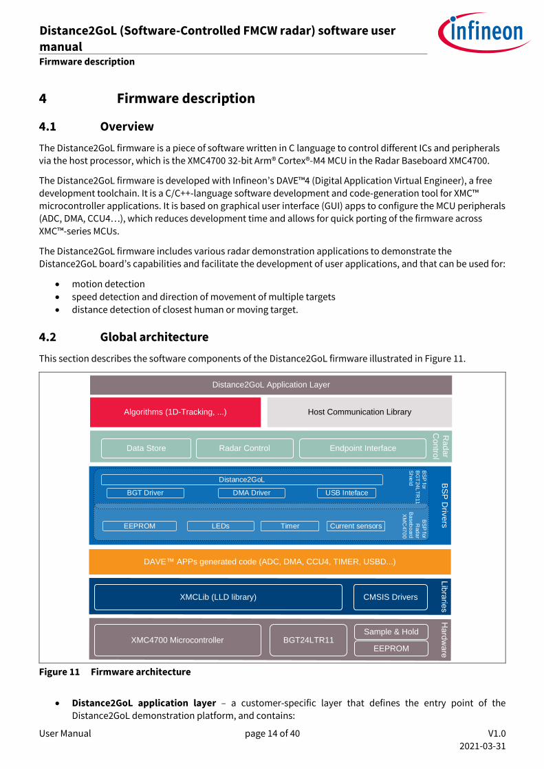
4.2 Global architecture
This section describes the software components of the Distance2GoL firmware illustrated in Figure 11.
DAVE APPs generated code (ADC, DMA, CCU4, TIMER, USBD...)
XMC4700 Microcontroller
Host Communication Library
XMCLib (LLD library) CMSIS Drivers
BS
P D
rive
rs
BGT24LTR11Sample & Hold
EEPROM
Ra
da
r
Co
ntro
l
Distance2GoL Application Layer
Algorithms (1D-Tracking, ...)
BGT Driver DMA Driver USB Inteface
Distance2GoL
Data Store Radar Control Endpoint Interface
EEPROM LEDs Timer Current sensors
BS
P fo
r
Rad
ar
Ba
seb
oard
XM
C47
00
BS
P fo
r
BG
T24
LT
R11
Sh
ield
Figure 11 Firmware architecture
• Distance2GoL application layer – a customer-specific layer that defines the entry point of the Distance2GoL demonstration platform, and contains:

User Manual page 15 of 40 V1.0
2021-03-31
Distance2GoL (Software-Controlled FMCW radar) software user
manual 24 GHz-based radar applications
Firmware description
o the initialization functions for XMC™ peripherals, host communication library and radar control layer
o the main application state machine
o a function template for the user to add their own code (data acquisition callbooks, algorithms process…).
• Algorithms – provided as a pre-compiled IP library, which contains the supported algorithms by the Distance2GoL demonstration platform implementations, e.g. range FFT used for processing and calculating information out of radar raw data in order to detect and track closest human or moving target
(refer to the 1D-tracking algorithm section for more details).
• Communication library – contains a set of functions to ensure USB data communication between the
Distance2GoL board and the Radar GUI tool:
o defines all communication endpoints
o contains communication endpoint settings and configurations
o contains a protocol communication layer.
• Radar control layer – contains high-level functions that can be used to set the specific mode for the Distance2GoL board, basically classified into three categories:
o radar control – offers high-level radar services to the user application and host communication
library layers, e.g. radar device initialization, radar start, radar stop, set/get calibration…
o data store – contains global structures for hardware settings and algorithm configurations
o endpoint interface – ensures communication between the host communication library and the
radar control layer.
• BSP driver – the Board Support Package (BSP) driver is a set of functions that can be used to control and
manage all components embedded in the Distance2GoL board, and it contains:
o low-layer functions to initialize and control the specific board features (BGT24LTR11, EEPROM,
LED…)
o functions to control power-up and power-down sequences for all hardware components
o functions to manage the data acquisition process from BGT to XMC™ microcontroller internal
RAM memory (DMA, timer, ADCs, DACs).
• DAVE™ apps generated code – contains the generated library sources from DAVE™-configured building-block apps for XMC4700 MCU peripherals. It contains Application Program Interfaces (APIs) and data structures meant to be used in application code.
• Libraries – contains the following libraries:
o CMSIS – Cortex® Microcontroller Software Interface Standard (CMSIS) is a vendor-independent hardware abstraction layer for the Cortex®-M processor series and defines generic tool interfaces.
The CMSIS enables consistent device support and establishes simple software interfaces to the processor and the peripherals, simplifying software reuse, reducing the learning curve for
microcontroller developers, and reducing the time-to-market for new devices.
User Manual page 16 of 40 V1.0
2021-03-31
Distance2GoL (Software-Controlled FMCW radar) software user
manual 24 GHz-based radar applications
Firmware description
o XMC-Lib – consists of various low-level drivers for the XMC™ microcontroller’s family peripherals. Each driver consists of a set of routines and data structures covering all peripheral functionalities. Built on top of the CMSIS, it provides access to all XMC4000 peripheral features.
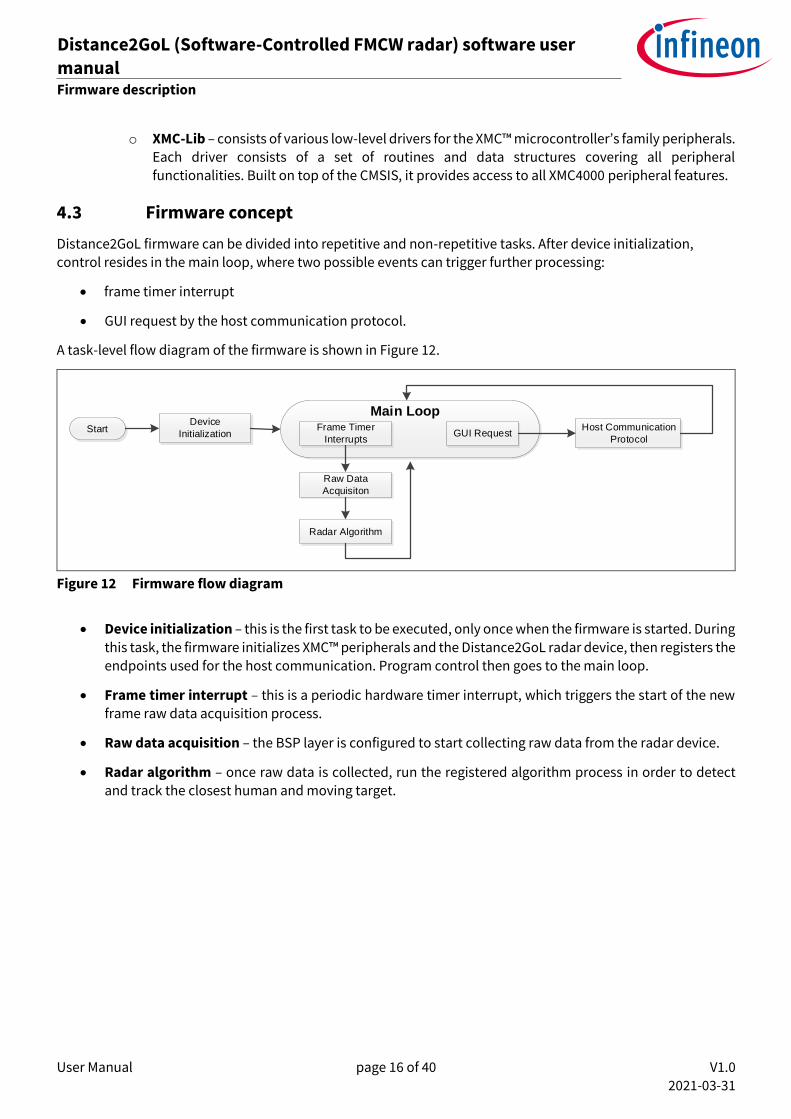
4.3 Firmware concept
Distance2GoL firmware can be divided into repetitive and non-repetitive tasks. After device initialization,
control resides in the main loop, where two possible events can trigger further processing:
• frame timer interrupt
• GUI request by the host communication protocol.
A task-level flow diagram of the firmware is shown in Figure 12.
Device
InitializationStart
Raw Data
Acquisiton
Radar Algorithm
Frame Timer
InterruptsGUI Request
Main LoopHost Communication
Protocol
Figure 12 Firmware flow diagram
• Device initialization – this is the first task to be executed, only once when the firmware is started. During
this task, the firmware initializes XMC™ peripherals and the Distance2GoL radar device, then registers the endpoints used for the host communication. Program control then goes to the main loop.
• Frame timer interrupt – this is a periodic hardware timer interrupt, which triggers the start of the new
frame raw data acquisition process.
• Raw data acquisition – the BSP layer is configured to start collecting raw data from the radar device.
• Radar algorithm – once raw data is collected, run the registered algorithm process in order to detect and track the closest human and moving target.
User Manual page 17 of 40 V1.0
2021-03-31
Distance2GoL (Software-Controlled FMCW radar) software user
manual 24 GHz-based radar applications
Firmware description
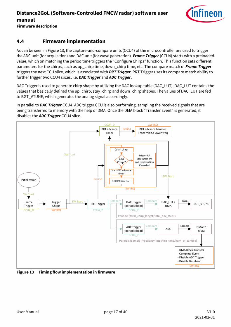
4.4 Firmware implementation
As can be seen in Figure 13, the capture-and-compare units (CCU4) of the microcontroller are used to trigger the ADC unit (for acquisition) and DAC unit (for wave generation). Frame Trigger (CCU4) starts with a preloaded
value, which on matching the period time triggers the “Configure Chirps” function. This function sets different parameters for the chirps, such as up_chirp time, down_chirp time, etc. The compare match of Frame Trigger
triggers the next CCU slice, which is associated with PRT Trigger. PRT Trigger uses its compare match ability to further trigger two CCU4 slices, i.e. DAC Trigger and ADC Trigger.
DAC Trigger is used to generate chirp shape by utilizing the DAC lookup table (DAC_LUT). DAC_LUT contains the
values that basically defined the up_chirp, stay_chirp and down_chirp shapes. The values of DAC_LUT are fed
to BGT_VTUNE, which generates the analog signal accordingly.
In parallel to DAC Trigger CCU4, ADC trigger CCU is also performing, sampling the received signals that are
being transferred to memory with the help of DMA. Once the DMA block “Transfer Event” is generated, it disables the ADC Trigger CCU4 slice.
PRT advance Timer
CCU4_0
SW Start
Trigger Chirps
SW IRQ
PRT Trigger
CCU4_2
PRT advance handler: From mid to lower freq
SW IRQ
- DMA Block Transfer - Complete Event - Disable ADC Trigger - Disable Baseband
SW IRQ
SW Start
SW Start
Period
Period
SW Start
SW IRQ
Last Chirp ?
Start PRT advance timer
Count chirps
Trigger RF Measurement
and recalibration if needed
Restart DAC_LUT
DAC Trigger(periodic beat)
CCU4_2
Frame Trigger
CCU4_0
ADC Trigger(periodic beat)
CCU4_2
DAC_LUT / DMA
ADC
BGT_VTUNE
DMA to MEM
Compare
Compare
DAC
sample
Periodic (Sample-Frequency) (upchirp_time/num_of_sample)
Periodic (total_chirp_lenght/total_dac_steps)
Compare
Initialization
Figure 13 Timing flow implementation in firmware

User Manual page 18 of 40 V1.0
2021-03-31
Distance2GoL (Software-Controlled FMCW radar) software user
manual 24 GHz-based radar applications
Firmware description
4.5 Raw data acquisition
Figure 14 shows the main blocks of the Distance2GoL raw data acquisition phase in detail, before going through the radar algorithm processing phase. There are more details about the chirp generation and data sampling
phases in the next sections.
IDLE
Frame 1 Frame 2 Frame 3 Frame 4 ...
Radar Algorithm Processing
GUI Requests
Data Acquisition
Chirp Generation Data Sampling
Frame Timer Interrupt
Figure 14 Raw data acquisition flow diagram
4.5.1 Chirp generation
Chirp generation is the first part of the data acquisition process; it is triggered by an internal frame timer, which will start generating chirps. The Distance2GoL firmware communicates with and controls the BGT via PWM signals. It generates periodic and continuous pulses based on the number of data samples required.
In order to keep the output frequency within the ISM band and generate the frequency ramp, the tuning voltage
is software-controlled via a DAC in the MCU. The concept is a software-based closed loop to periodically
measure the frequency and tune the voltage-controlled oscillator (VCO) accordingly for frequency control and ramp generation. Thus, an external hardware PLL is omitted, which saves cost, power and PCB space.
Figure 15 shows the flow diagram for FMCW chirp signal generation.
Chirp 2
TX ON
Post-chirp 2
Ramp N
TX OFF TX OFF
VCC ON
Post-chirp 1
Ramp 1FrameProlog
Soft Timer
DAC ramp/ADC
Ramp 2
VCC ON
TX ONTX ON
PRT (HW)
FrameEpilogChirp 1
Figure 15 FMCW chirp generation flow diagram
User Manual page 19 of 40 V1.0
2021-03-31
Distance2GoL (Software-Controlled FMCW radar) software user
manual 24 GHz-based radar applications
Firmware description
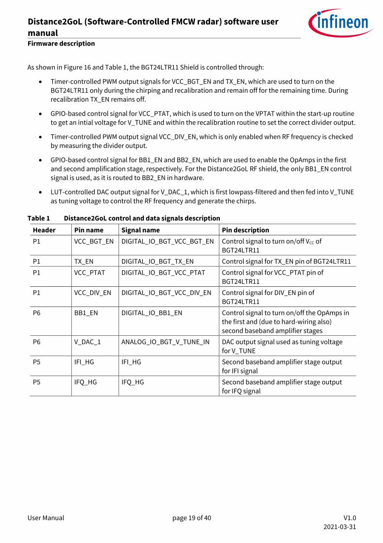
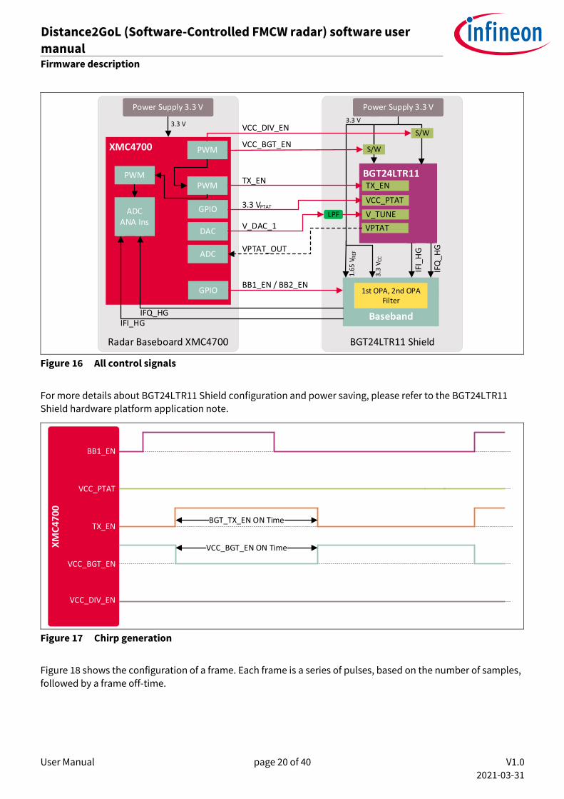
As shown in Figure 16 and Table 1, the BGT24LTR11 Shield is controlled through:
• Timer-controlled PWM output signals for VCC_BGT_EN and TX_EN, which are used to turn on the
BGT24LTR11 only during the chirping and recalibration and remain off for the remaining time. During recalibration TX_EN remains off.
• GPIO-based control signal for VCC_PTAT, which is used to turn on the VPTAT within the start-up routine
to get an intial voltage for V_TUNE and within the recalibration routine to set the correct divider output.
• Timer-controlled PWM output signal VCC_DIV_EN, which is only enabled when RF frequency is checked
by measuring the divider output.
• GPIO-based control signal for BB1_EN and BB2_EN, which are used to enable the OpAmps in the first
and second amplification stage, respectively. For the Distance2GoL RF shield, the only BB1_EN control signal is used, as it is routed to BB2_EN in hardware.
• LUT-controlled DAC output signal for V_DAC_1, which is first lowpass-filtered and then fed into V_TUNE
as tuning voltage to control the RF frequency and generate the chirps.
Table 1 Distance2GoL control and data signals description
Header Pin name Signal name Pin description
P1 VCC_BGT_EN DIGITAL_IO_BGT_VCC_BGT_EN Control signal to turn on/off VCC of
BGT24LTR11
P1 TX_EN DIGITAL_IO_BGT_TX_EN Control signal for TX_EN pin of BGT24LTR11
P1 VCC_PTAT DIGITAL_IO_BGT_VCC_PTAT Control signal for VCC_PTAT pin of
BGT24LTR11
P1 VCC_DIV_EN DIGITAL_IO_BGT_VCC_DIV_EN Control signal for DIV_EN pin of
BGT24LTR11
P6 BB1_EN DIGITAL_IO_BB1_EN Control signal to turn on/off the OpAmps in the first and (due to hard-wiring also)
second baseband amplifier stages
P6 V_DAC_1 ANALOG_IO_BGT_V_TUNE_IN DAC output signal used as tuning voltage
for V_TUNE
P5 IFI_HG IFI_HG Second baseband amplifier stage output
for IFI signal
P5 IFQ_HG IFQ_HG Second baseband amplifier stage output
for IFQ signal
User Manual page 20 of 40 V1.0
2021-03-31
Distance2GoL (Software-Controlled FMCW radar) software user
manual 24 GHz-based radar applications
Firmware description
BGT24LTR11 ShieldRadar Baseboard XMC4700
BGT24LTR11
XMC4700
Baseband
PWM
GPIO
GPIO
PWM
ADC ANA Ins
PWM
Power Supply 3.3 V
IFQ_HGIFI_HG
Power Supply 3.3 V
1st OPA, 2nd OPA Filter
VCC_PTAT
TX_EN
S/W
3.3 V
3.3
V
1.6
5 V
S/W
VCC_BGT_EN
TX_EN
BB1_EN / BB2_EN
REF
CC
DAC
ADC
V_TUNE
VPTAT
VPTAT_OUT
V_DAC_1
3.3 V VCC_DIV_EN
LPF
IFI_
HG
3.3 VPTAT
IFQ
_HG
Figure 16 All control signals
For more details about BGT24LTR11 Shield configuration and power saving, please refer to the BGT24LTR11 Shield hardware platform application note.
BB1_EN
VCC_PTAT
TX_EN
VCC_BGT_EN
VCC_DIV_EN
XM
C4
70
0
Figure 17 Chirp generation
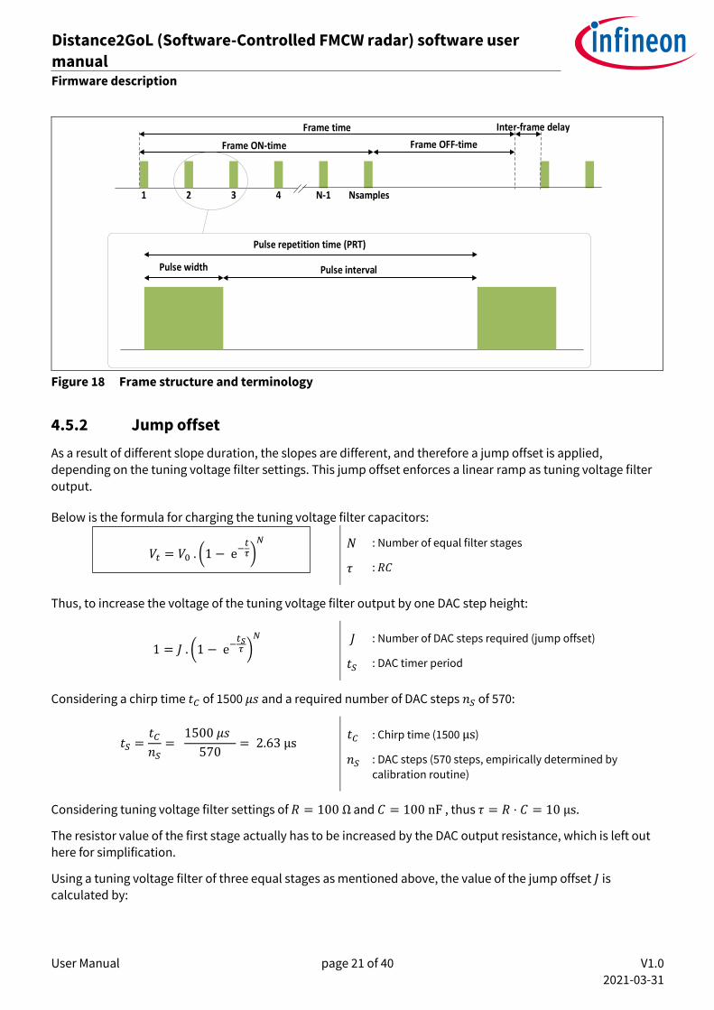
Figure 18 shows the configuration of a frame. Each frame is a series of pulses, based on the number of samples,
followed by a frame off-time.
User Manual page 21 of 40 V1.0
2021-03-31
Distance2GoL (Software-Controlled FMCW radar) software user
manual 24 GHz-based radar applications
Firmware description
1 32 4 N-1 Nsamples
Frame ON-time Frame OFF-time
Frame time
Pulse width Pulse interval
Pulse repetition time (PRT)
Inter-frame delay
Figure 18 Frame structure and terminology
4.5.2 Jump offset
As a result of different slope duration, the slopes are different, and therefore a jump offset is applied,
depending on the tuning voltage filter settings. This jump offset enforces a linear ramp as tuning voltage filter
output.
Below is the formula for charging the tuning voltage filter capacitors:
𝑉𝑡 = 𝑉0 . (1 − e−
𝑡𝜏)
𝑁
𝑁
𝜏
: Number of equal filter stages
: 𝑅𝐶
Thus, to increase the voltage of the tuning voltage filter output by one DAC step height:
1 = 𝐽 . (1 − e−
𝑡𝑆𝜏 )
𝑁
𝐽
𝑡𝑆
: Number of DAC steps required (jump offset)
: DAC timer period
Considering a chirp time 𝑡𝐶 of 1500 𝜇𝑠 and a required number of DAC steps 𝑛𝑆 of 570:
𝑡𝑆 =
𝑡𝐶
𝑛𝑆=
1500 𝜇𝑠
570= 2.63 μs
𝑡𝐶
𝑛𝑆
: Chirp time (1500 μs)
: DAC steps (570 steps, empirically determined by
calibration routine)
Considering tuning voltage filter settings of 𝑅 = 100 Ω and 𝐶 = 100 nF , thus 𝜏 = 𝑅 ⋅ 𝐶 = 10 μs.
The resistor value of the first stage actually has to be increased by the DAC output resistance, which is left out here for simplification.
Using a tuning voltage filter of three equal stages as mentioned above, the value of the jump offset 𝐽 is calculated by:
User Manual page 22 of 40 V1.0
2021-03-31
Distance2GoL (Software-Controlled FMCW radar) software user
manual 24 GHz-based radar applications
Firmware description
J = (1 − e−𝑡𝑠𝜏 )
−𝑁
= (1 − e−
1500𝑒−6
570100 × 100𝑒−9 )
−3
= 81
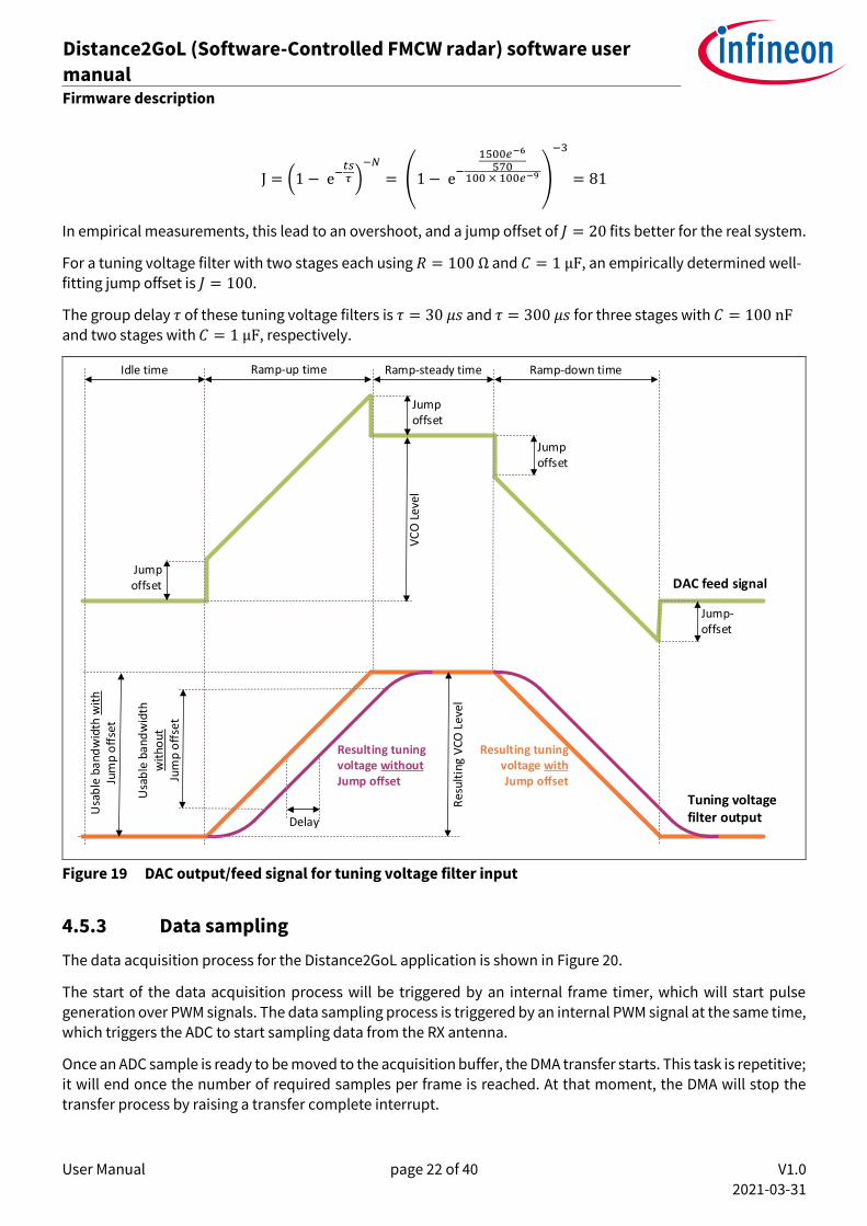
In empirical measurements, this lead to an overshoot, and a jump offset of 𝐽 = 20 fits better for the real system.
For a tuning voltage filter with two stages each using 𝑅 = 100 Ω and 𝐶 = 1 μF, an empirically determined well-
fitting jump offset is 𝐽 = 100.
The group delay 𝜏 of these tuning voltage filters is 𝜏 = 30 𝜇𝑠 and 𝜏 = 300 𝜇𝑠 for three stages with 𝐶 = 100 nF and two stages with 𝐶 = 1 μF, respectively.
Resulting tuning voltage without Jump offset
DAC feed signal
Tuning voltage filter output
Idle time Ramp-up time Ramp-steady time Ramp-down time
Jump offset
Jump offset
Jump offset
VC
O L
evel
Jump-offset
Res
ult
ing
VC
O L
evel
Usa
ble
ba
nd
wid
th w
ith
Jum
p o
ffse
t
Usa
ble
ban
dw
idth
wit
hou
t Ju
mp
off
set
Delay
Resulting tuning voltage with Jump offset
Figure 19 DAC output/feed signal for tuning voltage filter input
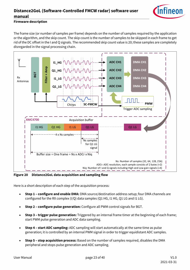
4.5.3 Data sampling
The data acquisition process for the Distance2GoL application is shown in Figure 20.
The start of the data acquisition process will be triggered by an internal frame timer, which will start pulse generation over PWM signals. The data sampling process is triggered by an internal PWM signal at the same time, which triggers the ADC to start sampling data from the RX antenna.
Once an ADC sample is ready to be moved to the acquisition buffer, the DMA transfer starts. This task is repetitive; it will end once the number of required samples per frame is reached. At that moment, the DMA will stop the
transfer process by raising a transfer complete interrupt.
User Manual page 23 of 40 V1.0
2021-03-31
Distance2GoL (Software-Controlled FMCW radar) software user
manual 24 GHz-based radar applications
Firmware description
The frame size (or number of samples per frame) depends on the number of samples required by the application or the algorithm, and the skip count. The skip count is the number of samples to be skipped in each frame to get rid of the DC offset in the I and Q signals. The recommended skip count value is 20; these samples are completely disregarded in the signal processing chain.
XMC4700 Acquisition buffer
Filt
er +
Am
p
BG
T
ADC CH1
ADC CH2
ADC CH3
ADC CH4
DMA CH1
DMA CH2
DMA CH3
DMA CH4
Ns: Number of samples (32, 64, 128, 256)ADCr: ADC resolution, each sample consists of 2 bytes (=2)
Niq: Number of I and Q signals including High and Low gain signals (=4)
I1_HG
Q1_HG
I1_LG
Q1_LG
Q1 LG
Chirps PMW
Trigger ADC sampling
I1 HG Q1 HG I1 LG Q1 LG
4 x Ns samples
Ns samplesfor Q1 LG
signal
Buffer size = One frame = Ns x ADCr x Niq
SC-FMCW
RxAntennas
Figure 20 Distance2GoL data acquisition and sampling flow
Here is a short description of each step of the acquisition process:
• Step 1 – configure and enable DMA: DMA source/destination address setup; four DMA channels are
configured for the RX complex (I/Q) data samples (Q1 HG, I1 HG, Q1 LG and I1 LG).
• Step 2 – configure pulse generation: Configure all PWM control signals for BGT.
• Step 3 – trigger pulse generation: Triggered by an internal frame timer at the beginning of each frame;
start PWM pulse generation and ADC data sampling.
• Step 4 – start ADC sampling: ADC sampling will start automatically at the same time as pulse generation; it is controlled by an internal PWM signal in order to trigger equidistant ADC samples.
• Step 5 – stop acquisition process: Based on the number of samples required, disables the DMA peripheral and stops pulse generation and ADC sampling.

User Manual page 24 of 40 V1.0
2021-03-31
Distance2GoL (Software-Controlled FMCW radar) software user
manual 24 GHz-based radar applications
Firmware description
4.6 Radar control layer
The Distance2GoL software package provides a simple interface to the radar kit through the radar control layer, which offers full flexibility to configure all radar parameters based on the application end requirements.
4.6.1 Radar control APIs
The APIs define the high-level interface used to configure the radar RF parameters, the behavior and capabilities of the component, and its inputs and outputs, and provide a set of firmware methods to manage
radar functionalities. Radar control APIs are called from the application layer and are prefixed by “radar_”.
Detailed technical information about the radar APIs available to the user is provided in a compiled HTML file in
the Firmware_Software/Documentation/FW_API folder, where all the functions and parameters are described.
4.6.2 Data store module
The data store module is apart from the radar control layer; it mainly contains the hardware device settings and the algorithm settings structures, as shown in Figure 21.
Figure 21 Data store hardware device and algorithm settings structures
User Manual page 25 of 40 V1.0
2021-03-31
Distance2GoL (Software-Controlled FMCW radar) software user
manual 24 GHz-based radar applications
Firmware description
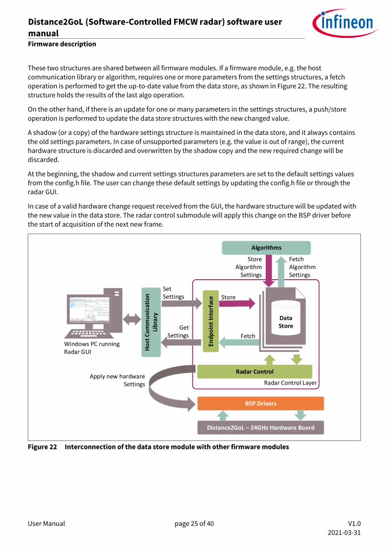
These two structures are shared between all firmware modules. If a firmware module, e.g. the host communication library or algorithm, requires one or more parameters from the settings structures, a fetch operation is performed to get the up-to-date value from the data store, as shown in Figure 22. The resulting structure holds the results of the last algo operation.
On the other hand, if there is an update for one or many parameters in the settings structures, a push/store
operation is performed to update the data store structures with the new changed value.
A shadow (or a copy) of the hardware settings structure is maintained in the data store, and it always contains
the old settings parameters. In case of unsupported parameters (e.g. the value is out of range), the current hardware structure is discarded and overwritten by the shadow copy and the new required change will be discarded.
At the beginning, the shadow and current settings structures parameters are set to the default settings values
from the config.h file. The user can change these default settings by updating the config.h file or through the radar GUI.
In case of a valid hardware change request received from the GUI, the hardware structure will be updated with
the new value in the data store. The radar control submodule will apply this change on the BSP driver before
the start of acquisition of the next new frame.
Radar Control Layer
Windows PC running Radar GUI
Radar Control
Ho
st C
om
mu
nic
atio
n
Lib
rary
Endp
oin
t In
terf
ace
Distance2GoL – 24GHz Hardware Board
Set Settings
Get Settings
StoreAlgorithm
Settings
Fetch Algorithm Settings
BSP Drivers
Algorithms
Store
Fetch
Apply new hardwareSettings
Data Store
Figure 22 Interconnection of the data store module with other firmware modules
User Manual page 26 of 40 V1.0
2021-03-31
Distance2GoL (Software-Controlled FMCW radar) software user
manual 24 GHz-based radar applications
Firmware description
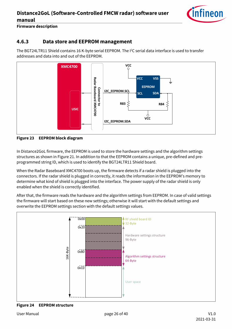
4.6.3 Data store and EEPROM management
The BGT24LTR11 Shield contains 16 K-byte serial EEPROM. The I2C serial data interface is used to transfer addresses and data into and out of the EEPROM.
EEPROM
VCC
VCC VSS
SCL
Co
nn
ecto
r to
Rad
ar Base
bo
ard X
MC
47
00
SDAI2C_EEPROM.SCL
I2C_EEPROM.SDAVCC
R83 R84
USIC
XMC4700
Figure 23 EEPROM block diagram
In Distance2GoL firmware, the EEPROM is used to store the hardware settings and the algorithm settings
structures as shown in Figure 21. In addition to that the EEPROM contains a unique, pre-defined and pre-programmed string ID, which is used to identify the BGT24LTR11 Shield board.
When the Radar Baseboard XMC4700 boots up, the firmware detects if a radar shield is plugged into the connectors. If the radar shield is plugged in correctly, it reads the information in the EEPROM’s memory to determine what kind of shield is plugged into the interface. The power supply of the radar shield is only
enabled when the shield is correctly identified.
After that, the firmware reads the hardware and the algorithm settings from EEPROM. In case of valid settings
the firmware will start based on these new settings; otherwise it will start with the default settings and
overwrite the EEPROM settings section with the default settings values.
0x00
0x20
0x80
0xC0
16
K-B
yte
RF shield board ID32-Byte
Hardware settings structure96-Byte
Algorithm settings structure64-Byte
User space
Figure 24 EEPROM structure
User Manual page 27 of 40 V1.0
2021-03-31
Distance2GoL (Software-Controlled FMCW radar) software user
manual 24 GHz-based radar applications
Firmware description
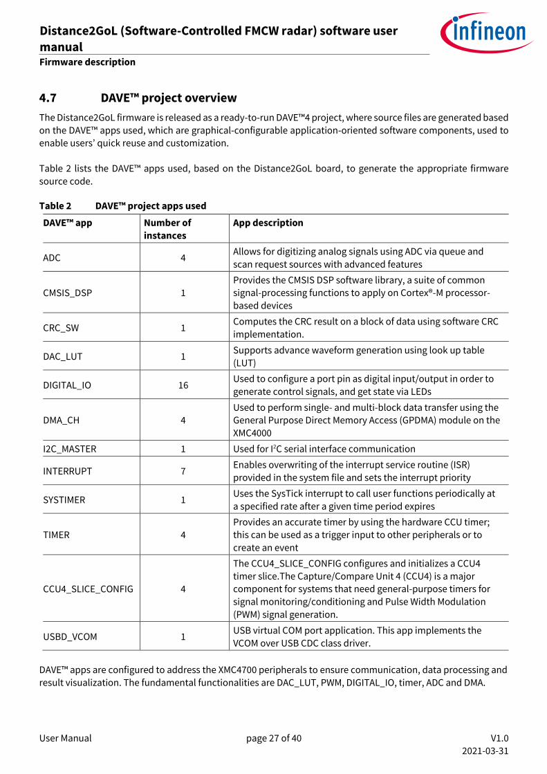
4.7 DAVE™ project overview
The Distance2GoL firmware is released as a ready-to-run DAVE™4 project, where source files are generated based
on the DAVE™ apps used, which are graphical-configurable application-oriented software components, used to enable users’ quick reuse and customization. Table 2 lists the DAVE™ apps used, based on the Distance2GoL board, to generate the appropriate firmware
source code.
Table 2 DAVE™ project apps used
DAVE™ app Number of
instances
App description
ADC 4 Allows for digitizing analog signals using ADC via queue and
scan request sources with advanced features
CMSIS_DSP 1
Provides the CMSIS DSP software library, a suite of common signal-processing functions to apply on Cortex®-M processor-
based devices
CRC_SW 1 Computes the CRC result on a block of data using software CRC
implementation.
DAC_LUT 1 Supports advance waveform generation using look up table
(LUT)
DIGITAL_IO 16 Used to configure a port pin as digital input/output in order to
generate control signals, and get state via LEDs
DMA_CH 4
Used to perform single- and multi-block data transfer using the
General Purpose Direct Memory Access (GPDMA) module on the
XMC4000
I2C_MASTER 1 Used for I2C serial interface communication
INTERRUPT 7 Enables overwriting of the interrupt service routine (ISR)
provided in the system file and sets the interrupt priority
SYSTIMER 1 Uses the SysTick interrupt to call user functions periodically at
a specified rate after a given time period expires
TIMER 4
Provides an accurate timer by using the hardware CCU timer;
this can be used as a trigger input to other peripherals or to
create an event
CCU4_SLICE_CONFIG 4
The CCU4_SLICE_CONFIG configures and initializes a CCU4
timer slice.The Capture/Compare Unit 4 (CCU4) is a major component for systems that need general-purpose timers for
signal monitoring/conditioning and Pulse Width Modulation
(PWM) signal generation.
USBD_VCOM 1 USB virtual COM port application. This app implements the
VCOM over USB CDC class driver.
DAVE™ apps are configured to address the XMC4700 peripherals to ensure communication, data processing and
result visualization. The fundamental functionalities are DAC_LUT, PWM, DIGITAL_IO, timer, ADC and DMA.

User Manual page 28 of 40 V1.0
2021-03-31
Distance2GoL (Software-Controlled FMCW radar) software user
manual 24 GHz-based radar applications
Firmware description
Table 3 PWM and GPIO pin configurations
Pin name Pin
functionality
Description
Control signals
DIGITAL_IO_BGT_VCC_BGT_EN Output P5.11 pin: Power
Enable/disable VCC 3.3 V power for BGT24LTR11
DIGITAL_IO_BGT_VCC_DIV_EN Output P5.7 pin: Power
Enable/disable VCC 3.3 V power for BGT24LTR11 divider
DIGITAL_IO_BGT_TX_EN Output P5.10 pin: Control
Control signal to enable/disable output power for
BGT24LTR11
DIGITAL_IO_BGT_VCC_PTAT Output P0.14 pin: Power
Provide 3.3 V for PTAT voltage source for BGT24LTR11
LED configuration
BLUE_LED Output P1.13 pin: Control
Turn on/off LED
GREEN_LED Output P1.14 pin: Control
Turn on/off LED
RED_LED Output P1.15 pin: Control
Turn on/off LED
• ADC configuration – the XMC4700 integrated 12-bit ADC is used to sample and process the analog down-converted signals in the baseband. The ADC peripheral configuration is set to:
o conversion mode: 12-bit resolution
o four channels, two channels for each IF (IF_I_HG, IF_Q_HG, IF_I_LG, IF_Q_LG), with two bytes per
sample for each ADC channel
o sample time [ns]: 75.
The ADC mode has an impact on the maximum possible sample rate. Higher resolution reduces the
maximum sample rate. Figure 25 shows the configuration of the ADC DAVE™ app:
Figure 25 ADC DAVE™ app configuration
User Manual page 29 of 40 V1.0
2021-03-31
Distance2GoL (Software-Controlled FMCW radar) software user
manual 24 GHz-based radar applications
Firmware description
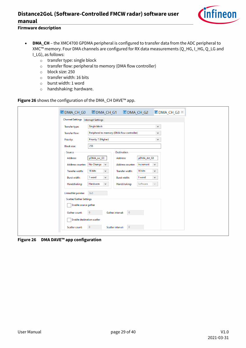
• DMA_CH – the XMC4700 GPDMA peripheral is configured to transfer data from the ADC peripheral to XMC™ memory. Four DMA channels are configured for RX data measurements (Q_HG, I_HG, Q_LG and I_LG), as follows:
o transfer type: single block
o transfer flow: peripheral to memory (DMA flow controller) o block size: 250 o transfer width: 16 bits o burst width: 1 word
o handshaking: hardware.
Figure 26 shows the configuration of the DMA_CH DAVE™ app.
Figure 26 DMA DAVE™ app configuration

User Manual page 30 of 40 V1.0
2021-03-31
Distance2GoL (Software-Controlled FMCW radar) software user
manual 24 GHz-based radar applications
Firmware description
4.8 Firmware package overview
D2GL_SC_FMCW is a firmware package for XMC™ microcontrollers and BGT24LTR11 radar chips. It provides a complete solution to build radar applications in a single package containing the source code for various
exemplary applications facilitating the development of user applications. Figure 28 shows a top-level view of the Distance2GoL package file structure.
Figure 27 Package folder structure
4.9 Footprint
The purpose of the following sections is to provide the memory requirements for all the Distance2GoL firmware
modules, including devices’ drivers, algorithms and main radar applications. The aim is to have an estimation of
fixed and customizable memory requirements in case of removal or addition of a module or feature. The footprint
data are provided for the following environments:
• Board – Distance2GoL (Radar Baseboard XMC4700 V2.0 + BGT24LTR11 Shield V3.0) • Firmware – D2GL_SC_FMCW (V1.0.0) • Toolchain – DAVE™ v4.4.2
After building a project, the build result is displayed in the console window, where the code size figures are listed. The values are organized according to memory areas, arranged by the linker file (*.ld) into the text, data and bss sections. Table 4 shows the Distance2GoL build memory utilization for the radar firmware configurations, main
modules and algorithms. The information has been gathered by analyzing the corresponding (*.elf) file.

User Manual page 31 of 40 V1.0
2021-03-31
Distance2GoL (Software-Controlled FMCW radar) software user
manual 24 GHz-based radar applications
Firmware description
Table 4 Distance2GoL firmware footprint
Firmware Footprint
Version DAVETM project Optimization Text(1)
[byte]
Data
[byte]
bss(2)
[byte]
Total [byte]
v1.0.0 D2GL_SC_FMCW None (-O0) 124900 2108 193120 320128 byte (0x4e280)
D2GL_SC_FMCW Optimize most (-O3) 89028 2096 193108 284232 byte (0x45648) (1) Text: code. (2) bss: statically allocated variables that are not explicitly initialized to any value.
4.10 Firmware timings
This section presents the typical timings of the Distance2GoL firmware that should be used to ensure correct execution of the important radar application sequences.
//
Frame Timer
Chirps
60 ms 40 ms
Frame ON Time Frame OFF Time
5 ms
Frame Period
Frame Settings: • Chirps per Frame: 10• Samples per Chirp: 64• Frame Rate: 10 Hz• Pulse Repetition Time: 5 ms• Ramp Up Time: 1.5 ms• Ramp Stay Time: 0.2 ms• Ramp Down Time: 0.3 ms
//
Figure 28 Raw data acquisition timings
User Manual page 32 of 40 V1.0
2021-03-31
Distance2GoL (Software-Controlled FMCW radar) software user
manual 24 GHz-based radar applications
Firmware description
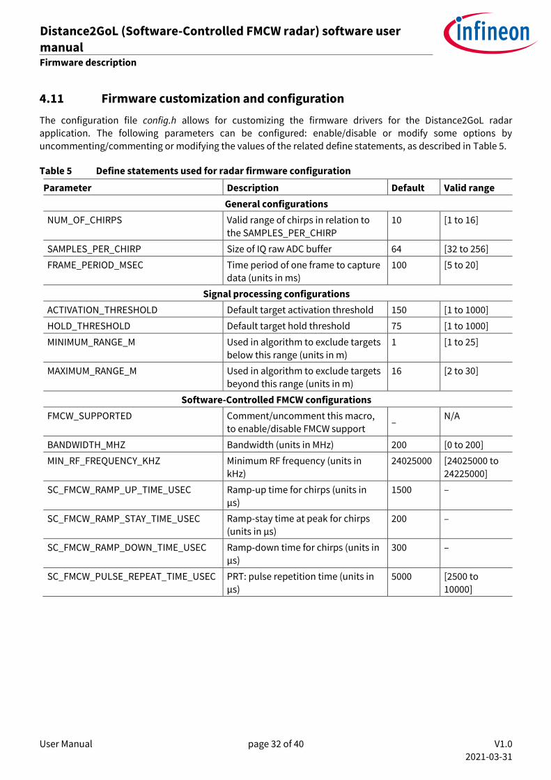
4.11 Firmware customization and configuration
The configuration file config.h allows for customizing the firmware drivers for the Distance2GoL radar application. The following parameters can be configured: enable/disable or modify some options by
uncommenting/commenting or modifying the values of the related define statements, as described in Table 5.
Table 5 Define statements used for radar firmware configuration
Parameter Description Default Valid range
General configurations
NUM_OF_CHIRPS Valid range of chirps in relation to
the SAMPLES_PER_CHIRP
10 [1 to 16]
SAMPLES_PER_CHIRP Size of IQ raw ADC buffer 64 [32 to 256]
FRAME_PERIOD_MSEC Time period of one frame to capture
data (units in ms)
100 [5 to 20]
Signal processing configurations
ACTIVATION_THRESHOLD Default target activation threshold 150 [1 to 1000]
HOLD_THRESHOLD Default target hold threshold 75 [1 to 1000]
MINIMUM_RANGE_M Used in algorithm to exclude targets
below this range (units in m)
1 [1 to 25]
MAXIMUM_RANGE_M Used in algorithm to exclude targets
beyond this range (units in m)
16 [2 to 30]
Software-Controlled FMCW configurations
FMCW_SUPPORTED Comment/uncomment this macro,
to enable/disable FMCW support –
N/A
BANDWIDTH_MHZ Bandwidth (units in MHz) 200 [0 to 200]
MIN_RF_FREQUENCY_KHZ Minimum RF frequency (units in
kHz)
24025000 [24025000 to
24225000]
SC_FMCW_RAMP_UP_TIME_USEC Ramp-up time for chirps (units in
µs)
1500 –
SC_FMCW_RAMP_STAY_TIME_USEC Ramp-stay time at peak for chirps
(units in µs) 200 –
SC_FMCW_RAMP_DOWN_TIME_USEC Ramp-down time for chirps (units in
µs)
300 –
SC_FMCW_PULSE_REPEAT_TIME_USEC PRT: pulse repetition time (units in
µs)
5000 [2500 to
10000]
User Manual page 33 of 40 V1.0
2021-03-31
Distance2GoL (Software-Controlled FMCW radar) software user
manual 24 GHz-based radar applications
1D-tracking algorithm
5 1D-tracking algorithm
This section describes the implemented 1D-tracking algorithm for distance and velocity detection and tracking
of the closest human or moving target.
On each chirp per frame, the range fast Fourier transform (FFT) is performed. In the next steps, only the range bins between minimum and maximum range are investigated. Here, the magnitudes of the range FFT data are
not used to detect and track the targets, but target activation data and target hold data are calculated and utilized. While target activation data is mainly used to detect targets and activate the tracks, target hold data is used to check if activated tracks are still alive. The algorithm outputs only the closest active track to the radar system.
The calculations of both data are enclosed in a library, but these data can be gathered via the communication library and also visualized in the radar GUI. Here, the magnitude spectrum of the range FFT data and the range
Doppler data are displayed as well, to compare the novel target activation data and target hold data used for target detection and tracking with the commonly used ones.
Via the communication library and Radar GUI, the performance of the algorithm can be adjusted:
• Minimum Range and Maximum Range – only targets within these two range limits are considered.
• Target Activation Threshold – peak in target activation data has to be above this threshold to be
detected.
• Target Hold Threshold – peak in target hold data has to be above this threshold to keep the corresponding active track alive.
• Activate CFAR – if activated, a CFAR-based peak detection is performed and the target activation threshold and target hold threshold are utilized as relative thresholds. In the plots for target activation
data and target hold data, the line positions remain the same, but the line style is changed from solid to dashed.
• Use Low Gain Input – if activated, the algorithm is performed on the low-gain data, which are scaled beforehand by 30 dB. The gain of the second amplification stage is not uniform, but 30 dB is its
approximate gain in the relevant baseband section. As a result of this scaling, the thresholds do not need to be adjusted much.
If system settings such as chirps per frame and frame rate are changed, the algorithm parameters are automatically adjusted as well. This could impact the magnitudes of the target activation data and target hold
data nevertheless, and the corresponding thresholds may need to be adjusted.
When chirps per frame is set to one, target activation data are not calculated any longer, and a special low-power mode is enabled. In this mode, only target hold data are investigated, and a target has to move radially with a speed of at least 0.6 m/s to activate a track.
User Manual page 34 of 40 V1.0
2021-03-31
Distance2GoL (Software-Controlled FMCW radar) software user
manual 24 GHz-based radar applications
RF frequency calibration
6 RF frequency calibration
The Distance2GoL board does not use a PLL for generating frequency ramps, but the tuning voltage is generated
by a DAC unit. Thus, a calibration routine is required to connect the DAC output voltages with an RF output frequency to ensure that the radar system always operates within the desired frequency band.
For the periodic RF frequency checks the BGT24LTR11 divider output is utilized. During all frequency checks and
within each calibration process TX is disabled to avoid sideband spurs. In the actual measurement process, TX is enabled and the divider is disabled, which leads to a frequency shift but is compensated in software. The calibration is split up into an initial boot-up calibration when the radar system is started, and an irregular recalibration procedure after the measurement process in a frame.
The recalibration procedure is only performed if the frequency check determines that the RF frequency is drifting out of the desired range. In the default system configuration with a chirp bandwidth of 200 MHz, the ideal
frequency range is 24.025 to 24.225 GHz, whereby the lower and upper corner frequencies may drift for ±5.0 MHz.
6.1 Initial boot-up calibration
In the first step of the initial boot-up calibration, BGT24LTR11 is enabled with TX disabled. The PTAT output voltage is measured with an ADC unit, and this voltage is set as tuning voltage via the DAC. This ensures an RF
output frequency within the ISM band (24.000 to 24.250 GHz), probably somewhere in the middle of this band. If the tuning voltage is decreased, the RF output frequency also decreases.
Thus, to determine a first value for the lower corner frequency, the calibration procedure stepwise decreases the
tuning voltage and measures the resulting RF until the measured frequency is below the upper limit for the lower corner frequency (24.030 GHz). Afterward, a first value for the upper corner frequency is determined by stepwise
increasing the tuning voltage and measuring the resulting RF frequency until the measured frequency is above
the lower limit for the upper corner frequency (24.220 GHz). In the last step of the boot-up calibration, the recalibration procedure is performed for fine-tuning of the corner frequencies.
6.2 Frame-wise frequency check and recalibration
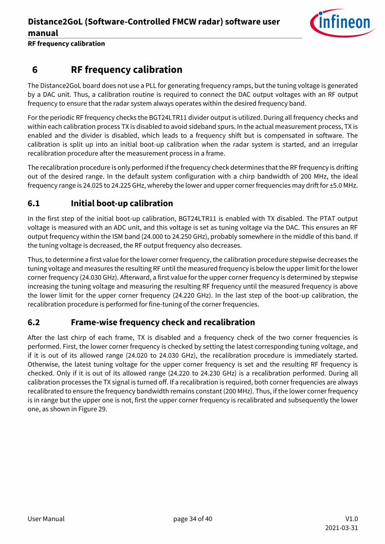
After the last chirp of each frame, TX is disabled and a frequency check of the two corner frequencies is
performed. First, the lower corner frequency is checked by setting the latest corresponding tuning voltage, and if it is out of its allowed range (24.020 to 24.030 GHz), the recalibration procedure is immediately started.
Otherwise, the latest tuning voltage for the upper corner frequency is set and the resulting RF frequency is checked. Only if it is out of its allowed range (24.220 to 24.230 GHz) is a recalibration performed. During all calibration processes the TX signal is turned off. If a recalibration is required, both corner frequencies are always
recalibrated to ensure the frequency bandwidth remains constant (200 MHz). Thus, if the lower corner frequency
is in range but the upper one is not, first the upper corner frequency is recalibrated and subsequently the lower
one, as shown in Figure 29.
User Manual page 35 of 40 V1.0
2021-03-31
Distance2GoL (Software-Controlled FMCW radar) software user
manual 24 GHz-based radar applications
RF frequency calibration
Figure 29 Calibration cycle, two frequency measurements
After recalibration, the tuning voltage is set back to mid-frequency. The corresponding DAC value is determined
by the mean value of the DAC values for lower and upper corner frequencies. In the actual recalibration procedure for both corner frequencies, another DAC value is set and its corresponding output frequency
measured next to the latest DAC value for the corresponding corner frequency. If the latest corner frequency is
too low (below 24.020 GHz or 24.220 GHz for lower or upper corner frequency, respectively), a larger intermediate
DAC value is set to enforce a higher RF frequency. Or, if the latest corner frequency is too high, then a smaller intermediate DAC value is set. In both cases the resulting RF frequency is measured. The new DAC value for chirp generation in the next frame is finally determined by the rule of three using the latest and intermediate DAC
values. As temperature changes especially lead to an RF frequency drift, recalibration is performed a lot shortly after powering-up the radar system. When (ambient) temperature is stable, the radar system can run for minutes without any need for recalibration.
Figure 30 exemplarily illustrates the frequency check and recalibration routine. The measured and calculated
frequency points are shown along several frames. Vertical dotted lines show the first frequency measurement of each frame. First the lower frequency is checked, then the upper one. The ordinate depicts the RF frequency
within the 24 GHz ISM band. The horizontal solid lines at 24.025 GHz and 24.225 GHz show the optimum lower and upper corner frequencies, respectively. The horizontal dashed lines represent the frequency boundaries for the lower and upper corner frequencies. (A) As long as both frequency checks are passed, here for frames 1-6, no recalibration is required. (B) In frame 7 the measured lower frequency is too low, for which reason both corner frequencies are recalibrated. Also the upper corner frequency is recalibrated to maintain a chirp bandwidth of
200 MHz. (C) Beginning with the subsequent frame after recalibration, both corner frequencies are again in bounds.

User Manual page 36 of 40 V1.0
2021-03-31
Distance2GoL (Software-Controlled FMCW radar) software user
manual 24 GHz-based radar applications
RF frequency calibration
Frames
Fre
qu
ency
(G
Hz)
1 2 3 4 5 5 7 8 9
24.25
24.2
24.15
24.1
24.05
24
A2: No calibration required for upper corner frequency
B4: Current upper corner frequency would be fine
B5: Temporary frequency measurement
B6: Calculated new upper corner frequency
C2: Upper corner frequency is also optimized again
A1: No calibration required for lower corner frequency
B1: Measured frequency is out of bounds
B3: Calculated new lower corner frequency
C1: Lower corner frequency is fine again
B2: Temporary frequency measurement
Figure 30 Calibration cycle
User Manual page 37 of 40 V1.0
2021-03-31
Distance2GoL (Software-Controlled FMCW radar) software user
manual 24 GHz-based radar applications
Authors
7 Authors
Radar Application Engineering Team, Business Line “Radio Frequency and Sensors”
User Manual page 38 of 40 V1.0
2021-03-31
Distance2GoL (Software-Controlled FMCW radar) software user
manual 24 GHz-based radar applications
References
8 References
[1] Infineon BGT24LTR11 – 24 GHz radar IC – datasheet
[2] Infineon XMC4700 32-bit Arm® Cortex®-M4 microcontroller – datasheet
[3] Infineon application note – AN305 – “User’s guide to 24 GHz radar transceiver”
[4] Infineon application note – AN553 – “24 GHz transceiver: BGT24LTR11”
User Manual page 39 of 40 V1.0
2021-03-31
Distance2GoL (Software-Controlled FMCW radar) software user
manual 24 GHz-based radar applications
Revision history
Revision history
Document
version
Date of release Description of changes
V1.0 2021-03-31 Initial version

Published by
Infineon Technologies AG
81726 Munich, Germany
© 2021 Infineon Technologies AG.
All Rights Reserved.
Do you have a question about this
document?
Email: [email protected]
Document reference
IMPORTANT NOTICE The information given in this document shall in no event be regarded as a guarantee of conditions or characteristics (“Beschaffenheitsgarantie”) . With respect to any examples, hints or any typical values stated herein and/or any information regarding the application of the product, Infineon Technologies hereby disclaims any and all warranties and liabilities of any kind, including without limitation warranties of non-infringement of intellectual property rights of any third party. In addition, any information given in this document is subject to customer’s compliance with its obligations stated in this document and any applicable legal requirements, norms and standards concerning customer’s products and any use of the product of Infineon Technologies in customer’s applications. The data contained in this document is exclusively intended for technically trained staff. It is the responsibility of customer’s technical departments to evaluate the suitability of the product for the intended application and the completeness of the product information given in this document with respect to such application.
For further information on the product, technology, delivery terms and conditions and prices please contact your nearest Infineon Technologies office (www.infineon.com).
WARNINGS Due to technical requirements products may contain dangerous substances. For information on the types in question please contact your nearest Infineon Technologies office. Except as otherwise explicitly approved by Infineon Technologies in a written document signed by authorized representatives of Infineon Technologies, Infineon Technologies’ products may not be used in any applications where a failure of the product or any consequences of the use thereof can reasonably be expected to result in personal injury.
Edition 2021-03-31
<UM_2101_PL32_2103_142014>
Trademarks All referenced product or service names and trademarks are the property of their respective owners.