Embed Size (px)
Citation preview

$SD.TDR-64-23
-Penetration Distance of Retrorocket ExhaustPlumes Intor an Oncoming Stream
11 MAY 1964
Prepared by S. E. r,,LLES, J. M. KALLISApplied Mechanics Divis ion
Prepared for COMMANDER. SPACE SYSTEMS DIVISION
UNITED STATES AIR FORCE
Ingleywd, California
* ASATELLITE SYSTEMS D!VISION .A I.ROS V-\C. ()R PORM 1\ H
CONTRACT NO. AF 04(695)-269
D! D
r 11N

Report No.SSD-TDR-64-23 TDR-269(4181)-Z
PENETRATION DISTANCE OF RETROROCisET EXHAUST PLUMES
INTO AN ONCOMING STREAM
by
S. E. Gilles, J. M. KallisApplied Mechanics Division
11 May 1964
AEROSPACE CORPORATIONEl Segundo, California
Contract No. AF 04(695)-269
Prepared for
COMMANDER SPACE SYSTEMS DIVISIONUNITED STATES AIR FORCE
Inglewood, California

Report No.? SSD-TDR-64-23 TDR-269(4181) -2
PENETRATICN DISTANCE OF RETROROCKET EXHAUST PLUMES
INTO AN ONCOMING STREAM
11 May 1964
This technical documentary report has been reviewed and is approved.
For Space Systems DivisionAir Force Systems Command: For Aerospace Corporation:
o"n V cliffe, A DirectorDirec or Engineering Sciel s SubdivisionStandard Launch Vehicle II
Syste s Engineerin.g DirectorSt dard Launch Vehicles Office
AEROSPACE CORPORATION
2400 East El Segundo BoulevardEl Segundo, California
Page v
ABSTRACT
A simple method for predicting the penetration distance
of highly underexpanded retrorocket exhau,;t plumes
into an oncoming free stream is developed and com-
pared with experimental data. It is shown that the
measured jet penetration distance and the standoff
distance of the free stream bow shock wave are pre-
dicted closelyby computing the plume flow field, using
the method of characteristics for an axisymmetric
p ume exhausting into still air at a pressure equal to
the oncoming free stream static pressure. The method
is applied to a single jet and to a cluster of n identical
jets. For the latter, the cluster is considered to be an
equivalent single retrorocket having the same mass-
flow rate (and thus an equivalent diameter (n)L1,times
as large as the nozzle exit diameter of a single rocket).
Page vii
NOMENCLATURE
D distance between retrorocket nozzle exit plane and free streambow shock wave
de retrorocket nozzle exit diametere
L distance between retrorocket nozzle exit plane and interface(between primary and secondary streams)
M Mach number
n number of plumes in cluster
P pressure
R = radius of cylindrical obstacle to free stream forned by clusterof n identical retrorocket plumes (see Figure 2)
X distance between retrorocket nozzle exit plane and jet shock wave
y = specific heat ratio
6 = distance between interface and free stream bow shock wave
= Mach angle = sin - 1 (l/M)
9 divergence half-angle of retrorocket nozzle at exit plane
Subscripts
0o = free stream conditions
e = jet conditions at retrorocket nozzle exit plane
j = jet conditions at jet shock wave
n = values for a cluster of n identical retrorockets
t total or stagnation conditions
1 = values for a single retrorocket

Page ix
CONTENTS
Page
1. INTRODUCTION .. ....... ....... ........... 1
II. METHOD OF CALCULATION .. .. ...... ....... ... 3
III. EFFECT OF MULTIPLE JETS .. .. ....... ........ 7
IV. COMPARISON OF CALCULATION TECHNIQUE WITH
EXPERIMENTAL DATA............................. 11
V. SUMMARY OF CALCULATION PROCEDURE............. 13
REFERENCES....................................... 15

T
Page I
I. INTRODUCTION
The interaction between forward facing jets exhausting from, or
adjacent to, a body and an oncoming free stream has been studied exten-
sively. This situation occurs when using retrorocket thrust for such
purpose, as decelerating a vehicle, alleviating aerodynamic heating at the
nose of a blunt body, and altering the pressure distribution and drag of a
body (see Reference I for summary and bibliography). When a retrorocket
is used adjacent to a vehicle, the exhaust plume affects heating of the vehicle
skin by the plume, communication between the ground and the vehicle, and
the trajectories of other bodies near the vehicle. Solutions to these problems
require knowledge of the distance that retrorocket exhaust plumes penetrate
into an oncoming stream.
Measurements of the penetration distance were made by several experi-
menters (References 2 through 6). It was shown (References 2 and 5) that
the standoff distance of the free stream bow shock wave could be predicted
accurately, using the measured penetration distance. Peterson and McKenzie
(Reference 3) suggested using the method of characteristics to determine the
plume flow field'for this problem, but they did not apply their analysis to
predict the penetration distance. Romeo and Sterrett (Reference 4) attempted
to predict the penetration distance, using the two-dimensional method of
characteristics to compute the plume flow field. However, an unknown
parameter in their anaivsis was the ambient pressure acting on the plume,
and their predictions were sensitive to this parameter. This is the result
of applying the two-dimensional method of characteristics to an axisymmetric
flow field.
This report presents a simple method for calculating the penetration
distance for a single retrorocket, and for a cluster of n identical retro-
rockets. In this method, the following contributions which are essential to the
solution of this problem are made:

Page 2
a. It is pointed out that, for a highly underexpanded exhaust
plume, the distance X to the jet shock, as predicted using the axisymmetric
method of characteristics, is independent of the ambient pressure acting on
the plume.
b., It is shown that the distance X for a cluster of n identical
retrorockets can be determined accurately, using a modification of single
plume results, thus eliminating the difficulty of computing the complex
multiple plume flow field.
c. It is shown that the bow shock standoff distance (D) is predicted
accurately by computing the plume flow field, using the method of character-
istics for an axisymmetric plume exhausting into still air with pressure equal
to the oncoming free stream static pressure.
The validity of this prediction method is demonstrated by obtaining close
agreement between predictions and the available experimental data, in which
parameters were varied over wide ranges.

Page 3
II. METHOD OF CALCULATION
The flow model used in calculating the penetration distance of the
retrorocket plume into the oncoming free stream is pictured in Figure 1.
This idealized model assumes that the plume is an axisymmetric jet,
expanding into an opposing uniform free stream of known Mach number and
total pressure. The jet terminates when it reaches a mutual stagnation
point with the free stream in which the total pressures of the two streams
are equal. This mutual stagnation point is determined by assuming that the
jet expands along the axis until a Mach number M. is reached at which a
normal shock wave will reduce the total jet pressure to a value equal to the
total pressure following a normal shock wave in the free stream. (This jet
shock wave is different from the Riemann wave (References 7 and 81 and
occurs closer than the Riemann wave to the jet nozzle exit plane.) The
distance X from the nozzle exit to the jet shock is calculated from the
knowledge of the variation of axial Mach number in the plume. This model
is described in more detail in References I and 5.
The variation of plume Mach number along the axis is determined by a
method of characteristics flow field calculation for an axisyrnmetric plume
with a constant pressure boundary (i. e. , a plume exhausting into still air).
If the nozzle is highly underexpanded, then the axial Mach number variation
is independent of the boundary pressure. This was true of all the cases for
which computations were made.
For a single jet, it was assumed that the plume forms an obstacle to the
free stream in the shape of a sphere of radius L (the distance from the
nozzle exit to the interface between Lie free stream and jet flows). This
assumption has been shown to yield close agreement with measured free
stream bow shock wave standoff distances, using experimentally determined
values of L (Reference 2). Because the distance L -hat is to be used in
calculating the standoff distance 6 is itseif dependent on 6 (see Equation(l)),

Page 4
TYPICAL FREE STREAMSTREAMLINE
INTERFACE /-FREE STREAMN' ',E.._ /BOW SHOCK
TYPICAL JET STREAMLINE
SHOCK MFREE STREAMi, " ~M.0... , P0a
~ " -MUTUAL
LD STAGNATION01 POINT
FFoSST-ePLUJeBOUNDARYi
Figure 1. Flow Model for Single Jet.
Page 5
the jet-shock distance X can be used as an approximation to L, for
high values of M O , for example, M > 3 (Reference 9). For low values
of MO (M < 3), an iterative process must be used. The bow shock wave
standoff distance 6 can then' be determined for flow over a sphere of radius
X l , for low (Reference 9) or high (Reference 10) free stream Mach numbers.
The distance between the jet shock wave and the interface (between the
primary and secondary streams) is assumed to be equal to 6. This assump-
tion is based on experimental results (References 2 and 5). Thus, the total
penetration distance L of the exhaust gases into the oncoming stream is
given by
L1 = X 1+ 61 (1)
and the distance to the free stream bow shock wave is
D, = L 1 4 6 1 z X 1 4 261 (2)

VT-
Page 7
III. EFFECT OF MULTIPLE JETS
Good correlation of the analytical calculation with the measured plume
penetration distance of four clustered rockets (Reference 3) was achieved by
multiplying the calculated single jet shock distance X1 by the square root of
the number of clustered rockets. This was derived by considering the cluster
to be an equivalent single jet with the same total mass flow rate as the cluster
of four jets. This equivalent single jet will have a nozzle exit diarneter (n) 1/2
times as large as the nozzle exit diameter of each member of the cluster
(where n = number of rockets in cluster), because the mass-flow rate throc-gh
a nozzle varies as the square of the nozzle diameter. it is well known that
physical dimensions of jets with equal nczzle exit conditions scale linearly
with the nozzle exit diameter. In particular, the jet shock distance X scales
in this manner. Thus, the jet shock distance for n retrorockets is
Xn = (n) 1/2 X 1 (3)
The above is a plausible, but certainly not rigorous, explanation of the
multiple jet correlation factor, which is shown (in the next section) to be
successful in obtaining agreement with the only available experimental data.
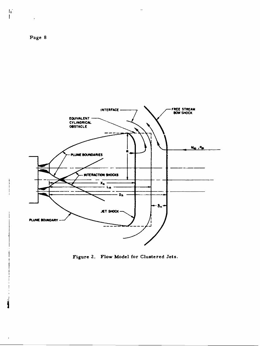
For a cluster of jets, the obstacle formed by the cluster of plumes is
expected to be flat-nosed, rather than spherical, in shape (see Figure 2).
It was assumed that the obstacle can be approximated by a cylinder whose
axis is parallel to the free-strean direction. Good correlation with experi-
mental measurements (Reference 3) was achieved by assuming the flat-faced
cylinder radius R to be equal to the distance from the cluster centerline to
the outer boundary of the cluster of plumes at station X .n
The outer boundary of the cluster plume can be determined from the flow
field calculation for an individual jet because the boundary of each of the four
plumes would not be expected to be affected by impingement. -t--pa me-en -- on
each other, as long as the intersection between the shock wave which is pro-
duced by impingement of the jets on each other and the jet boundary occurs
downstream of X .
Page 8
INTERFACE FREE STREAMBOW SHOCK
EQUIVALENTCYLINDRICAL
OBTAL
Figure ~ ~ ~ ~ ~ ~ m 2.Fo oelfrCuteeees

O T
Page 9
ThusL = X " 8 = (n) 1/ 2 X 4 6n (4)
and
D L + 6 =(n)1 / X 26 (5)n (5)
where 6 is determined from Reference 9 for flow around a flat-nosed
cylinder of radius R.
Examination of Schlieren photographs (Reference 3) verified that each
term in Equation (5) is predicted closely by this method. It should be noted
that, for very highly expanded plumes, where the cluster plume radius is much
larger than X , this procedure may not be applicable.

Page 11
IV. COMPARMON OF CALCULATION TECHNIQUE WITHEXPERIMENTAL DATA
The calculation technique was compared with some available experi-
mental data (References 2 through 4) to check the validity of the technique.
The experiments were performed under a wide variety of conditions, so
that a good test of the accuracy of the calculation method could be made.
The supersonic jet data from Reference 2 and the data from Reference 6
were not used for this comparison because these plumes were over-
expanded, or just barely underexpanded. The present study was restricted
to plumes which are highly underexpanded, and the flow phenomenon for
underexpanded jets is quite different from that for overexpanded jets
(References 1 and Z).
The predicted and measured values of D are compared in Table 1.
Note the reasonably close agreement between the theory and the experi-
ment for the sonic jet tests (Reference 2) and the very close agreement
for the supersonic jet tests (References 3 and 4). A possible explanation
for the larger difference between theory and experiment for the sonic jet
case than for the supersonic jet cases is the difficulty in computing the
flow field in a sonic jet using the method of characteristics (Reference 8).

t9
Table 1. Comparison of Predicted and Measured;
o Eq. usedSoureof Me / e de (in.) to Calc. (thiData OD e PiJlC, (dees) e (
Figure Sc,Reference 4 6.0 3.03 4000 18 0.107 2 0.(single jet)
Figure 3c,Reference3 1.9 3.0O 1345 15 0. 412 3.(four -jetcluster)**Figure 3a,
Reference3 1.5 3.02 582 is 0.412 s .(four-jet .cluster)
Figures 17and 16,Reference 2 2.91 1.O00 220 0 2(single jet)
Y.2Y 1.4
The retrorockets were placed 90 degrees apart on a circle with a diexit Jiameter
tA Mach 1. 0038 jet (which corresponds to an exit Mach angle we of a
of a sonic jet (Pe = 90 degrees), because of the difficulty of computiicomputer program (Reference 8)
tfThe measured values of L also are given in Reference 2, and they

--d Shock Wave Detachment Distances.
X 6 D D(theory) (theory) (theory) (exp.) Differencei(in. ) On. ) (in. ) (in. ) (S)
0.65 0.098 o.846 0.851 0.6
3.5 Z.32 11.65 11.5 1.3
2.88 3.02 11.79 11.5 2.5
3.5 0.70 4.715 5.69 Z0. 2 t
a diameter 5. I times the retrorocket nozzle
of 85 degrees) was used for this comparison instead3uting a sonic jet on the method of characteristics
Ley are 13. 2 per cent higher than the predicted values.

Page 13
V. SUMMARY OF CALCULATION PROCEDURE
Close agreement was obtained between the predicted and measured
values of D (distances between the retrorocket nozzle exit plane and the
free stream bow shock wave) using the following technique:
a. Determine the plume flow field using the method of charac-
teristics for a plume exhausting into still air whose pressure is the on-
coming free stream static pressure.
b. Compute X by taking X as the axial station at which the
plume has reached a Mach number M, at which the jet will shock to a
total pressure equal to the total pressure behind the free stream shock.
c. For a single jet, determine 6 by assuming that the jet forms
an obstacle to the free stream in the shape of a sphere of radius X + 6
(*aX for large values of M 0).
d. For a cluster of n identical jets, determine 6 by assuming
that the cluster forms an obstacle to the free stream in the shape of a flat-
nosed cylinder whose radius R is the radius of an individual plume at
station X plus the distance between the cluster centerline and the plumen
centerline.
e. For a single jet, compute D from Equation (Z).
f. For a cluster of n identical jets, compute D from Equation (5).

Page 15
REFERENCES
1. Kallis, J. M. , and Adelberg, M., "Recent Advances in the FluidDynamics of Gas injection for Thrust-Vector and Trajectory Control,"Aerospace Corp. Report No. ATN-63(3305)-3 (15 July 1963); also to bepublished in Bull. 1963 Interagency Solid Propulsion Meeting 4.
2. Hayman, L. 0., Jr., and McDearmon, R. W., "Jet Effects onCylindrical Afterbodies Housing Sonic and Supersonic Nozzles whichExhaust Against a Supersonic Stream at Angles of Attack from 900 to1800, " NASA TN D-1016 (March 1962).
3. Peterson, V. L. , and McKenzie, R. L. , "Effects of Simulated Retro-rockets on the Aerodynamic Characteristics of a Body of Revolution atMach Numbers from 0. 25 to 1. 90," NASA TN D- 1300 (May 1962).
4. Romeo, D. J., and Sterrett, J. R., "Exploratory Investigation of theEffect of a Forward-Facing Jet on the Bow Shock of a Blunt Body in aMach Number 6 Free Stream," NASA TN D-1605 (February 1963).
5. Watts, G. A. , "An Experimental Investigation of a Sonic Jet DirectedUpstream Against a Uniform Supersonic Flow," UTIA Technical Noteo. 7 (January 1956).
6. "Investigation of an Aerodynamic Spike in Hypersonic Flow," AirborneInstruments Lab. Report No. 1198-1, Contract AF 04(694)-29 (Secret)(June 1962).
7. Eastman, D. W., and Radtke, L. P., "Location of the Normal ShockWave in the Exhaust Plume of a Jet," AIAA J. 1, 918-919 (1963).
8. Love, E. S. , et al., "Experimental and Theoretical Studies ofAxisymmetric Free Jets, " NASA TR R-6(1959).
9. Liepmann, H. W., and Roshko, A., Elements of Gasdynamics (JohnWiley & Sons Inc., New York, 1957), p. 105.
10. Choudhury, P. R., "Shock-Standoff Distance for Spherical Bodies atHigh Mach Numbers, " J. Aerospace Sci. 29, 745 (1962).