Embed Size (px)
Citation preview
Dissipative and Dispersive Optomechanics in a Nanocavity Torque Sensor
Marcelo Wu,1,2 Aaron C. Hryciw,2 Chris Healey,1,2 David P. Lake,1 Harishankar Jayakumar,1
Mark R. Freeman,2,3 John P. Davis,3 and Paul E. Barclay1,2*1Institute for Quantum Science and Technology, University of Calgary,
Calgary, Alberta T2N 1N4, Canada2National Institute for Nanotechnology, Edmonton, Alberta T6G 2M9, Canada
3Department of Physics, University of Alberta, Edmonton, Alberta T6G 2E9, Canada(Received 25 March 2014; revised manuscript received 12 May 2014; published 19 June 2014)
Dissipative and dispersive optomechanical couplings are experimentally observed in a photonic crystalsplit-beam nanocavity optimized for detecting nanoscale sources of torque. Dissipative coupling of upto approximately 500 MHz/nm and dispersive coupling of 2 GHz/nm enable measurements of sub-pgtorsional and cantileverlike mechanical resonances with a thermally limited torque detection sensitivityof 1.2 × 10⁻²⁰ Nm=
ffiffiffiffiffiffiHz
pin ambient conditions and 1.3 × 10⁻²¹ Nm=
ffiffiffiffiffiffiHz
pin low vacuum. Interference
between optomechanical coupling mechanisms is observed to enhance detection sensitivity and generate amechanical-mode-dependent optomechanical wavelength response.
DOI: 10.1103/PhysRevX.4.021052 Subject Areas: Magnetism, Nanophysics, Photonics
Optical measurement and control of mechanical vibra-tions are at the heart of many technological and funda-mental advances in physics and engineering, from sensitivedisplacement and force detection [1–9] to proposed obser-vation of gravitational waves [10] and studies of thequantum properties [11] of massive objects [12–14].Nanophotonic implementations of cavity-optomechanicalsystems [15] localize light to subwavelength volumes,enhancing optomechanical coupling between photonsand phonons of nanomechanical structures [6,16,17].Harnessing this optomechanical interaction has enabledmilestone experiments, including ground-state cooling[13,18], mechanical squeezing of light [19], and optome-chanically induced transparency [20,21]. Typically,optomechanical coupling arises in cavity-optomechanicalsystems from a dispersive dependence of the nanocavityresonance frequency on the nanocavity geometry, whichis modulated by mechanical excitations. In this paper,we demonstrate that dissipative optomechanical coupling,where mechanical excitations modulate the nanocavityphoton lifetime, can also play a crucial role in the opticaltransduction of nanomechanical motion. In particular,we demonstrate the dissipative-enhanced optomechanicalreadout of a cantilever integrated directly within a nano-cavity and realize an optomechanical torque detector whosesensitivity of approximately 1.3 × 10⁻²¹ Nm=
ffiffiffiffiffiffiHz
pprom-
ises to significantly advance detection of phenomena instudies of nanomagnetic [22,23] and mesoscopic [24]
condensed-matter systems, optical angular momentum[25], and magnetometry [26]. We also observe interferencebetween dissipative and dispersive coupling mechanisms,which reveals details of the nature of the nanomechanicalmotion and may open new avenues in optomechanicalcontrol [27–31].The nanocavity optomechanical system studied here, an
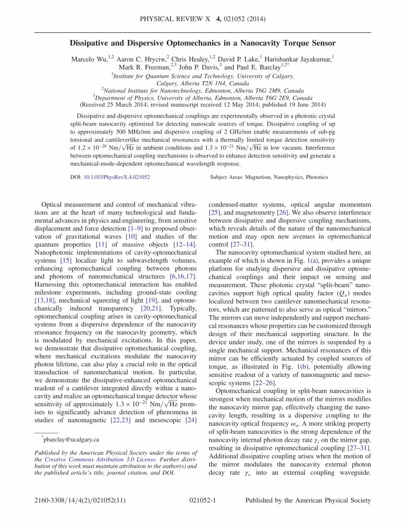
example of which is shown in Fig. 1(a), provides a uniqueplatform for studying dispersive and dissipative optome-chanical couplings and their impact on sensing andmeasurement. These photonic crystal “split-beam” nano-cavities support high optical quality factor (Qo) modeslocalized between two cantilever nanomechanical resona-tors, which are patterned to also serve as optical “mirrors.”The mirrors can move independently and support mechani-cal resonances whose properties can be customized throughdesign of their mechanical supporting structure. In thedevice under study, one of the mirrors is suspended by asingle mechanical support. Mechanical resonances of thismirror can be efficiently actuated by coupled sources oftorque, as illustrated in Fig. 1(b), potentially allowingsensitive readout of a variety of nanomagnetic and meso-scopic systems [22–26].Optomechanical coupling in split-beam nanocavities is
strongest when mechanical motion of the mirrors modifiesthe nanocavity mirror gap, effectively changing the nano-cavity length, resulting in a dispersive coupling to thenanocavity optical frequency ωo. A more striking propertyof split-beam nanocavities is the strong dependence of thenanocavity internal photon decay rate γi on the mirror gap,resulting in dissipative optomechanical coupling [27–31].Additional dissipative coupling arises when the motion ofthe mirror modulates the nanocavity external photondecay rate γe into an external coupling waveguide.
Published by the American Physical Society under the terms ofthe Creative Commons Attribution 3.0 License. Further distri-bution of this work must maintain attribution to the author(s) andthe published article’s title, journal citation, and DOI.
PHYSICAL REVIEW X 4, 021052 (2014)
2160-3308=14=4(2)=021052(11) 021052-1 Published by the American Physical Society
These interactions can be probed by monitoring fluctua-
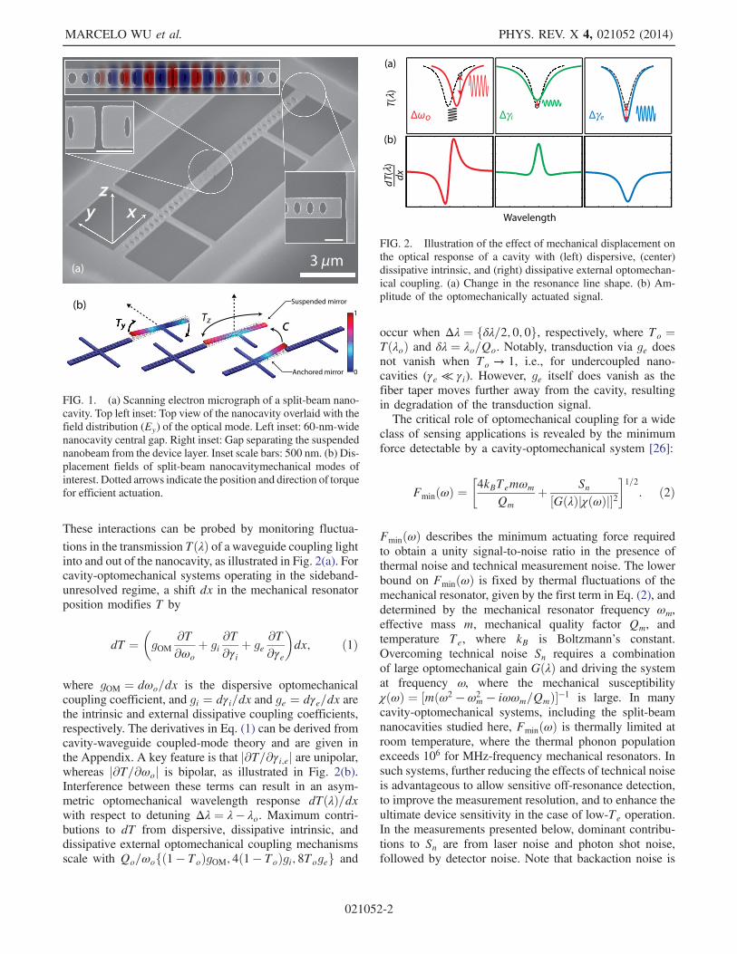
tions in the transmission TðλÞ of a waveguide coupling lightinto and out of the nanocavity, as illustrated in Fig. 2(a). Forcavity-optomechanical systems operating in the sideband-unresolved regime, a shift dx in the mechanical resonatorposition modifies T by
dT ¼�gOM
∂T∂ωo
þ gi∂T∂γi þ ge
∂T∂γe
�dx; ð1Þ
where gOM ¼ dωo=dx is the dispersive optomechanicalcoupling coefficient, and gi ¼ dγi=dx and ge ¼ dγe=dx arethe intrinsic and external dissipative coupling coefficients,respectively. The derivatives in Eq. (1) can be derived fromcavity-waveguide coupled-mode theory and are given inthe Appendix. A key feature is that j∂T=∂γi;ej are unipolar,whereas j∂T=∂ωoj is bipolar, as illustrated in Fig. 2(b).Interference between these terms can result in an asym-metric optomechanical wavelength response dTðλÞ=dxwith respect to detuning Δλ ¼ λ − λo. Maximum contri-butions to dT from dispersive, dissipative intrinsic, anddissipative external optomechanical coupling mechanismsscale with Qo=ωofð1 − ToÞgOM; 4ð1 − ToÞgi; 8Togeg and
occur when Δλ ¼ fδλ=2; 0; 0g, respectively, where To ¼TðλoÞ and δλ ¼ λo=Qo. Notably, transduction via ge doesnot vanish when To → 1, i.e., for undercoupled nano-cavities (γe ≪ γi). However, ge itself does vanish as thefiber taper moves further away from the cavity, resultingin degradation of the transduction signal.The critical role of optomechanical coupling for a wide
class of sensing applications is revealed by the minimumforce detectable by a cavity-optomechanical system [26]:
FminðωÞ ¼�4kBTemωm
Qmþ Sn½GðλÞjχðωÞj�2
�1=2
: ð2Þ
FminðωÞ describes the minimum actuating force requiredto obtain a unity signal-to-noise ratio in the presence ofthermal noise and technical measurement noise. The lowerbound on FminðωÞ is fixed by thermal fluctuations of themechanical resonator, given by the first term in Eq. (2), anddetermined by the mechanical resonator frequency ωm,effective mass m, mechanical quality factor Qm, andtemperature Te, where kB is Boltzmann’s constant.Overcoming technical noise Sn requires a combinationof large optomechanical gain GðλÞ and driving the systemat frequency ω, where the mechanical susceptibilityχðωÞ ¼ ½mðω2 − ω2
m − iωωm=QmÞ�−1 is large. In manycavity-optomechanical systems, including the split-beamnanocavities studied here, FminðωÞ is thermally limited atroom temperature, where the thermal phonon populationexceeds 106 for MHz-frequency mechanical resonators. Insuch systems, further reducing the effects of technical noiseis advantageous to allow sensitive off-resonance detection,to improve the measurement resolution, and to enhance theultimate device sensitivity in the case of low-Te operation.In the measurements presented below, dominant contribu-tions to Sn are from laser noise and photon shot noise,followed by detector noise. Note that backaction noise is
FIG. 2. Illustration of the effect of mechanical displacement onthe optical response of a cavity with (left) dispersive, (center)dissipative intrinsic, and (right) dissipative external optomechan-ical coupling. (a) Change in the resonance line shape. (b) Am-plitude of the optomechanically actuated signal.
FIG. 1. (a) Scanning electron micrograph of a split-beam nano-cavity. Top left inset: Top view of the nanocavity overlaid with thefield distribution (Ey) of the optical mode. Left inset: 60-nm-widenanocavity central gap. Right inset: Gap separating the suspendednanobeam from the device layer. Inset scale bars: 500 nm. (b) Dis-placement fields of split-beam nanocavitymechanical modes ofinterest. Dotted arrows indicate the position and direction of torquefor efficient actuation.
MARCELO WU et al. PHYS. REV. X 4, 021052 (2014)
021052-2
not included in Eq. (2), due to its negligible effect in theregime of operation studied here.The optomechanical gain GðλÞ ¼ ηgtijdT=dxðλÞjPi is
determined by Eq. (1), and, for a given waveguide inputpower Pi, waveguide transmission efficiency η, and photo-detector gain gti, can be increased through large gOM;i;e,high Qo, and optimally tuning λ within the nanocavityoptical mode linewidth. As discussed above, dissipativeexternal coupling can play an important role in maximizingG. However, dissipative coupling is often small comparedto dispersive contributions and, to date, has only beenreported experimentally in hybrid cavity-nanomechanicalsystems where ge ∼ 10–20 MHz=nm [32,33]. In the split-beam nanocavities studied below, measurements indicatethat gOM ∼ 2 GHz=nm, gi ∼ 300–500 MHz=nm, andge ∼ 2–3 MHz=nm.The split-beam nanocavity devices studied here are
fabricated from silicon-on-insulator chips consisting of a220-nm-thick silicon (Si) layer on a 3-μm-thick silicon-dioxide (SiO2) layer. Using electron-beam lithography,reactive-ion etching, and a hydrofluoric acid undercut,pairs of cantilever photonic crystal mirrors are defined,with a 60-nm gap between them and another at one mirrorend. The resulting split-beam photonic crystal nanocavities,whose design is described in Ref. [34], support high-Qooptical modes with ωo=2π ∼ 200 THz (λo ∼ 1550 nm).The mirror pattern consists of a periodic array of holes,whose dimensions are tapered from circles to ellipticalshapes with a profile similar to the gap. Crucially, the bandedge of the photonic crystal “air mode” associated with thegap unit cell is phase matched with the band edge of theneighboring elliptical hole unit-cell air mode, minimizingradiation loss in the gap region and creating a smooth“optical potential” for localized modes [34–36]. The high-Qo optical mode supported in the gap region has a fielddistribution shown in Fig. 1(a) and is characterized by amode volume Vo ∼ 0.3ðλo=nSiÞ3 and radiation loss limitedQo ∼ 104–106, depending on the minimum realizablefeature size [34]. The design utilized here is predictedfrom finite-element simulations (COMSOL) to support amode with Qo ∼ 3.5 × 10⁴.The split-beam nanocavity supports several cantilever-
like mechanical resonances suitable for torque detection,whose displacement profiles, calculated from simulationsand illustrated in Fig. 1(b), are characterized by effectivemass m ∼ 350–800 fg and frequency ωm=2π ∼ 5–8 MHz(see Table I). The two lowest-frequency modes involvepivoting of the suspended mirror about its support. They aretorsional in the y and z directions and are thus labeled Tyand Tz, respectively. The third mode C is an out-of-planecantileverlike mode of the triply anchored mirror.The optomechanical properties of the split-beam nano-
cavities are measured using a dimpled optical fiber-taperwaveguide to evanescently couple light into and out of thenanocavity. The dimple is fabricated by modifying the
process in Ref. [37] to use a ceramic dimple mold.Measurements are performed both in ambient conditionsand in vacuum. A tunable laser source is used to measureTðλÞ, with the taper either hovering approximately 300–500 nm above the nanocavity or touching one of thenanocavity mirrors. The nanocavity studied here supportsan optical mode at λo ∼ 1530 nm, with unloaded Qo ∼12 000 due to fabrication imperfections, resulting in a dip inTðλÞ near λo, as shown in Fig. 3(a). Optomechanicalcoupling between this mode and nanocavity mechanicalresonances is studied by measuring the rf voltage noisespectrum SVVðλ;ωÞ of the optical power transmittedthrough the fiber taper, using a photoreceiver (NewFocus 1811, detector noise 2.5 nW=
ffiffiffiffiffiffiHz
p) and a real-time
spectrum analyzer (Tektronix RSA5106A). A typicalmeasurement of SVV, with the fiber hovering above thenanocavity and Δλ ∼ −δλo=2, is shown on the right ofFig. 3(a). Three distinct resonances are visible, indicative ofthe optomechanical transduction of the thermal motionof the Ty, Tz, and C modes. The resonances are identifiedwith mechanical modes through comparison of measuredand simulated ωm and by observing the effect of touchingthe fiber taper on each of the mirrors. As shown in Fig. 3(b),when the fiber contacts the anchored (suspended) mirror,the C (Ty and Tz) resonance is suppressed, as it is aresonance of the anchored (suspended) mirror.The mechanical displacement sensitivity of these mea-
surements can be calibrated from SVVðω ¼ ωmÞ, which isdetermined by the thermal amplitude of the mechanicalresonance [7,8]. From the measured and calculatedmechanical mode properties listed in Table I, the noise-floor displacement resolutions jz; xjNF for the Ty and Tzmodes of approximately 6 and 7 fm=
ffiffiffiffiffiffiHz
p, respectively,
are measured for Pi ∼ 25 μW. The minimum detectabletorque τmin associated with the angular motion θ of eachmechanical mode can be calculated from τ ¼ r × F andEq. (2). From the mirror length of 7.5 μm and supportlength of 3 μm, a thermally limited torque sensitivityof the Ty and Tz modes, in ambient conditions, ofτmin ∼ 1.2 × 10⁻²⁰ Nm=
ffiffiffiffiffiffiHz
p, and on-resonance technical
noise floors of4–7 × 10⁻²² Nm=ffiffiffiffiffiffiHz
p, limitedby laser noise
and photon shot noise, are extracted. This technical noisefloor, corresponding to the second term in Eq. (2), has aneffective temperature in the mK range. Measurements are
TABLE I. Split-beam nanocavity mechanical mode properties.
Mechanical mode Ty Tz C
ωm=2π (MHz) 4.9 6.4 7.7m (fg) 427 805 348Qm (ambient) 21 83 42Qm (vacuum) 1800 4400 2400jz; xjNF (ambient) (fm=
ffiffiffiffiffiffiHz
p) 6.3 6.9 � � �
jτjmin (ambient) (Nm=ffiffiffiffiffiffiHz
p) 1.2 × 10⁻²⁰ 1.2 × 10⁻²⁰ � � �
jτjmin (vacuum) (Nm=ffiffiffiffiffiffiHz
p) 1.3 × 10⁻²¹ 1.7 × 10⁻²¹ � � �
DISSIPATIVE AND DISPERSIVE OPTOMECHANICS IN A … PHYS. REV. X 4, 021052 (2014)
021052-3
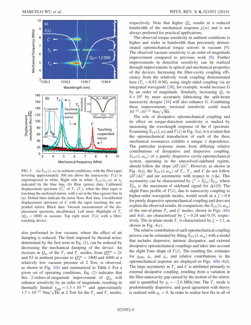
also performed in low vacuum, where the effect of airdamping is reduced. The limit imposed by thermal noise,determined by the first term in Eq. (2), can be reduced bydecreasing the mechanical damping of the device. Anincrease in Qm of the Ty and Tz modes, from Qatm
m ¼ 21and 83 in ambient pressure to Qvac
m ¼ 1800 and 4400 at arelatively low vacuum pressure of 2 Torr, is observed,as shown in Fig. 3(b) and summarized in Table I. For agiven set of operating conditions, Eq. (2) indicates thatthis 2-orders-of-magnitude improvement of Qm willenhance sensitivity by an order of magnitude, resulting inthermally limited τmin ∼ 1.3 × 10⁻²¹ and approximately1.7 × 10−21 Nm=
ffiffiffiffiffiffiHz
pat 2 Torr for the Ty and Tz modes,
respectively. Note that higher Qm results in a reducedbandwidth of the mechanical response χðωÞ and is notalways preferred for practical applications.The observed torque sensitivity in ambient conditions is
higher and wider in bandwidth than previously demon-strated optomechanical torque sensors in vacuum [9].The observed vacuum sensitivity is an order-of-magnitudeimprovement compared to previous work [9]. Furtherimprovements in detection sensitivity can be realizedthrough improvements in optical and mechanical propertiesof the devices. Increasing the fiber-cavity coupling effi-ciency from the relatively weak coupling demonstratedhere (To ∼ 0.92–0.98), using single-sided coupling via anintegrated waveguide [38], for example, would increase Gby an order of magnitude. Similarly, increasing Qo to4 × 105 by more accurately fabricating the split-beamnanocavity designs [34] will also enhance G. Combiningthese improvements, torsional sensitivity could reach10−23–10−22 Nm=
ffiffiffiffiffiffiHz
p.
The role of dissipative optomechanical coupling andits effect on torque-detection sensitivity is studied bymeasuring the wavelength response of the rf spectrum.Examining SVVðλ;ωÞ and TðλÞ in Fig. 3(a), it is evident thatthe optomechanical transduction of each of the threemechanical resonances exhibits a unique λ dependence.The particular response stems from differing relativecontributions of dissipative and dispersive coupling.SVVðλ;ωmÞ of a purely dispersive cavity-optomechanicalsystem, operating in the unresolved-sideband regime,should follow the slope jdT=dλj2. However, as shown inFig. 4(a), the SVVðλ;ωmÞ of Ty, Tz, and C do not followjdT=dλj2 and are asymmetric with respect to �Δλ. Thisasymmetry can be characterized by ζ2 ¼ SþVV=S
−VV, where
S�VV is the maximum rf sideband signal for Δλ≷0. Theslight Fano profile of TðλÞ, due to nanocavity coupling tohigher-order waveguide modes, would result in a ζ ∼ 0.8for purely dispersive optomechanical coupling and does notexplain the observed results. In comparison, the SVVðλ;ωmÞof the out-of-plane Ty and C modes, shown in Figs. 4(b)and 4(d), are characterized by ζ ∼ 0.24 and 0.19, respec-tively. The in-plane mode Tz is characterized by ζ ∼ 1.1, asshown in Fig. 4(c).The relative contribution of each optomechanical coupling
process can be estimated by fitting SVVðλ;ωmÞ with a modelthat includes dispersive, intrinsic dissipative, and externaldissipative optomechanical couplings and takes into accountthe slight Fano shape of TðλÞ. The resulting fits, estimatesfor gOM, gi, and ge, and relative contributions to theoptomechanical response are displayed in Figs. 4(b)–4(d).The large asymmetry in Ty and C is attributed primarily toexternal dissipative coupling, resulting from a variation inthe fiber-nanocavity gap caused by the motion of the mirror,and is quantified by ge ∼ −2.6 MHz=nm. The Tz mode ispredominantly dispersive, and good agreement with theoryis realized with ge ¼ 0. In order to realize best fits in all of
FIG. 3. (a) SVVðλ;ωÞ in ambient conditions, with the fiber taperhovering approximately 300 nm above the nanocavity; TðλÞ issuperimposed in white. Right side in white: SVVðλb;ωÞ at λbindicated by the blue line. (b) Blue (green) data: Calibrateddisplacement spectrum S1=2xx of Ty (Tz), when the fiber taper istouching the anchored mirror, with λ set at the blue (green) line in(a). Dotted lines indicate the noise floor. Red data: Uncalibrateddisplacement spectrum of C with the taper touching the sus-pended mirror. Black data: Vacuum measurement of the dis-placement spectrum, uncalibrated. Left inset: Highlight of Ty(Qm ¼ 1800) in vacuum. Top right inset: TðλÞ with a fiber-touching device.
MARCELO WU et al. PHYS. REV. X 4, 021052 (2014)
021052-4
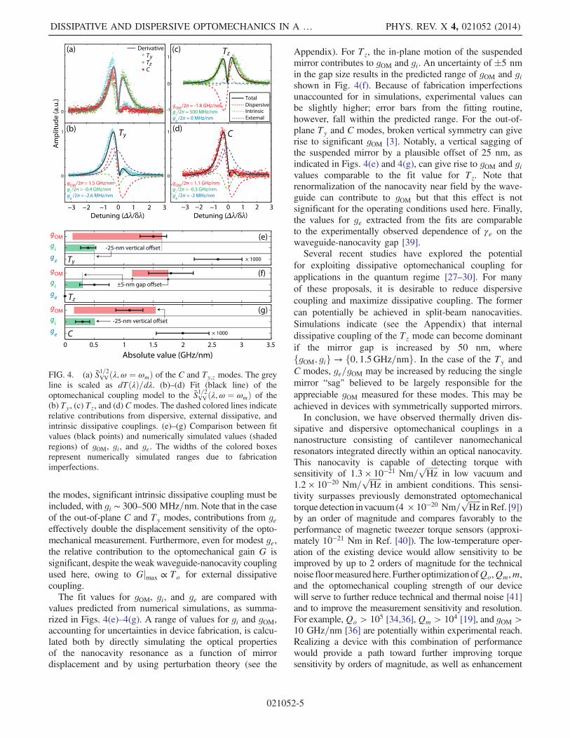
the modes, significant intrinsic dissipative coupling must beincluded, with gi ∼ 300–500 MHz=nm. Note that in the caseof the out-of-plane C and Ty modes, contributions from geeffectively double the displacement sensitivity of the opto-mechanical measurement. Furthermore, even for modest ge,the relative contribution to the optomechanical gain G issignificant, despite theweak waveguide-nanocavity couplingused here, owing to Gjmax ∝ To for external dissipativecoupling.The fit values for gOM, gi, and ge are compared with
values predicted from numerical simulations, as summa-rized in Figs. 4(e)–4(g). A range of values for gi and gOM,accounting for uncertainties in device fabrication, is calcu-lated both by directly simulating the optical propertiesof the nanocavity resonance as a function of mirrordisplacement and by using perturbation theory (see the
Appendix). For Tz, the in-plane motion of the suspendedmirror contributes to gOM and gi. An uncertainty of �5 nmin the gap size results in the predicted range of gOM and gishown in Fig. 4(f). Because of fabrication imperfectionsunaccounted for in simulations, experimental values canbe slightly higher; error bars from the fitting routine,however, fall within the predicted range. For the out-of-plane Ty and C modes, broken vertical symmetry can giverise to significant gOM [3]. Notably, a vertical sagging ofthe suspended mirror by a plausible offset of 25 nm, asindicated in Figs. 4(e) and 4(g), can give rise to gOM and givalues comparable to the fit value for Tz. Note thatrenormalization of the nanocavity near field by the wave-guide can contribute to gOM but that this effect is notsignificant for the operating conditions used here. Finally,the values for ge extracted from the fits are comparableto the experimentally observed dependence of γe on thewaveguide-nanocavity gap [39].Several recent studies have explored the potential
for exploiting dissipative optomechanical coupling forapplications in the quantum regime [27–30]. For manyof these proposals, it is desirable to reduce dispersivecoupling and maximize dissipative coupling. The formercan potentially be achieved in split-beam nanocavities.Simulations indicate (see the Appendix) that internaldissipative coupling of the Tz mode can become dominantif the mirror gap is increased by 50 nm, wherefgOM; gig → f0; 1.5GHz=nmg. In the case of the Ty andC modes, ge=gOM may be increased by reducing the singlemirror “sag" believed to be largely responsible for theappreciable gOM measured for these modes. This may beachieved in devices with symmetrically supported mirrors.In conclusion, we have observed thermally driven dis-
sipative and dispersive optomechanical couplings in ananostructure consisting of cantilever nanomechanicalresonators integrated directly within an optical nanocavity.This nanocavity is capable of detecting torque withsensitivity of 1.3 × 10⁻²¹ Nm=
ffiffiffiffiffiffiHz
pin low vacuum and
1.2 × 10⁻²⁰ Nm=ffiffiffiffiffiffiHz
pin ambient conditions. This sensi-
tivity surpasses previously demonstrated optomechanicaltorque detection invacuum (4 × 10⁻²⁰ Nm=
ffiffiffiffiffiffiHz
pinRef. [9])
by an order of magnitude and compares favorably to theperformance of magnetic tweezer torque sensors (approxi-mately 10−21 Nm in Ref. [40]). The low-temperature oper-ation of the existing device would allow sensitivity to beimproved by up to 2 orders of magnitude for the technicalnoise floormeasuredhere. Further optimizationofQo,Qm,m,and the optomechanical coupling strength of our devicewill serve to further reduce technical and thermal noise [41]and to improve the measurement sensitivity and resolution.For example,Qo > 105 [34,36],Qm > 104 [19], and gOM >10 GHz=nm [36] are potentially within experimental reach.Realizing a device with this combination of performancewould provide a path toward further improving torquesensitivity by orders of magnitude, as well as enhancement
FIG. 4. (a) S1=2VVðλ;ω ¼ ωmÞ of the C and Ty;z modes. The greyline is scaled as dTðλÞ=dλ. (b)–(d) Fit (black line) of theoptomechanical coupling model to the S1=2VVðλ;ω ¼ ωmÞ of the(b) Ty, (c) Tz, and (d) Cmodes. The dashed colored lines indicaterelative contributions from dispersive, external dissipative, andintrinsic dissipative couplings. (e)–(g) Comparison between fitvalues (black points) and numerically simulated values (shadedregions) of gOM, gi, and ge. The widths of the colored boxesrepresent numerically simulated ranges due to fabricationimperfections.
DISSIPATIVE AND DISPERSIVE OPTOMECHANICS IN A … PHYS. REV. X 4, 021052 (2014)
021052-5
of the relative strength of dissipative optomechanicalcoupling.
This work is supported by the Natural Science andEngineering Research Council of Canada (NSERC), theCanada Foundation for Innovation (CFI), and AlbertaInnovates Technology Futures (AITF). We give specialthanks to Hamidreza Kaviani, Brad D. Hauer, and AashishA. Clerk for helpful discussions. We also thank the staff ofthe nanofabrication facilities at the University of Albertaand at the National Institute for Nanotechnology for theirtechnical support.
APPENDIX
1. Dispersive and dissipativeoptomechanical coupling
Below, we present equations describing the wavelengthdependence of the split-beam photonic crystal nanocavityoptomechanical response. This model takes into accountdissipative and dispersive optomechanical coupling. It alsomodifies the usual waveguide-cavity temporal coupled-mode theory to include indirect coupling between thecavity and the fundamental waveguide mode, mediatedby higher-order modes of the waveguide.The detected optical signal consists of the output field in
the fundamental mode of an optical fiber-taper waveguidepositioned in the near field of the optical cavity. Thepolarization of this mode is chosen to maximize itscoupling to the cavity. The modal output amplitude is
to ¼ so þ κcoaþ κcþa; ðA1Þwhere so is the input field amplitude and a is the cavity-field amplitude. Coupling from the cavity field into thefundamental fiber-taper mode is described by couplingcoefficients κco and κcþ. κco describes coupling from thecavity directly into the fundamental fiber-taper mode, whileκcþ describes coupling into higher-order modes of thefiber taper that are converted into the fundamental modealong the length of the fiber taper. Typically, jκcþj ≪ jκcoj,as both the cavity to higher-order mode-coupling processand the fiber-taper higher-order to fundamental modeconversion rates are small.The cavity-field amplitude is governed by the equation
of motion
dadt
¼ −�iΔþ γt
2
�aþ κocso; ðA2Þ
where Δ ¼ ωl − ωc is the detuning between the input fieldlaser and the cavity frequency, and κoc is the fiber-to-cavitycoupling coefficient. The total cavity-optical loss rate isgiven by
γt ¼ γiþp þ 2γe; ðA3Þ
where γe is the coupling rate into the forward (or backward)propagating mode of the fiber taper, and γiþp describes theintrinsic cavity loss and fiber-induced parasitic loss intomodes other than the fundamental fiber-taper mode, e.g.,scattering into radiation modes and light coupled intohigher-order fiber modes that are not converted into thefundamental waveguide mode within the fiber taper.In the steady state, _a ¼ 0, and the cavity-field amplitude
is
a ¼ κocsoiΔþ γt
2
: ðA4Þ
In the case of a two-port coupler, unitarity requires thatκoc ¼ −κ�co ¼ i
ffiffiffiffiffiγe
pfor the phase convention chosen in
Eq. (A1). Assuming that the correction due to coupling tohigher-order taper modes considered here is small, so thatthe above relationship still holds, the transmitted field is
to ¼ so
�1 − γe þ κocκcþ
iΔþ γt2
�: ðA5Þ
A key property of the output coupling mediated by thehigher-order waveguide mode is that a priori the complexphase of κcþ is not defined relative to the phase of κoc, as itdepends on the modal coupling process between thecavity’s coupling region and the fiber taper. This variablephase leads to a non-Lorentzian cavity response, as seen bywriting κcþ ¼ κrþ þ iκiþ, where κrþ and κiþ are both real, andcalculating the normalized taper transmission
T ¼ Δ2 þ ðγiþp
2Þ2 þ 2
ffiffiffiffiffiγe
pκrþΔ − ffiffiffiffiffi
γep
κiþγiþp
Δ2 þ ðγt2Þ2 ; ðA6Þ
where we have only kept terms to lowest order in κi;rþ . Forweak fiber-cavity coupling γe ≪ γiþp, the last term in thedenominator can be ignored, and
T ∼Δ2 þ ðγiþp
2Þ2 þ CfγeΔ
Δ2 þ ðγt2Þ2 ; ðA7Þ
where Cf ¼ 2κrþ=ffiffiffiffiffiγe
prepresents a Fano modification to
the cavity response mediated by the higher-order fiber-tapermodes and is expected to be small.The optomechanical response of our cavity can be
modeled by considering the dependence of the parametersin Eq. (A7) on the mechanical state x of the mechanicalresonance of interest. In the unresolved-sideband regime,where the mechanical frequency is small compared to theoptical linewidth ωm ≪ γt, the fiber transmission adiabati-cally follows the mechanical oscillations. The amplitude ofthe optical oscillations for a given mechanical displacementamplitude dx is
MARCELO WU et al. PHYS. REV. X 4, 021052 (2014)
021052-6
dTdx
ðΔÞ ¼����gOM ∂T
∂Δþ gi∂T∂γi þ ge
∂T∂γe
����; ðA8Þ
where gOM ¼ dωo=dx is the dispersive optomechanicalcoupling coefficient [36], gi ¼ dγi=dx is the intrinsicdissipative coupling coefficient, and ge ¼ dγe=dx is theexternal dissipative coupling coefficient. The derivativesof Eq. (A7) are
∂T∂Δ ¼ 2Δð1 − TÞ þ γeCf
Δ2 þ ðγt=2Þ2; ðA9Þ
∂T∂γi ¼
γiþp − Tðγiþp þ 2γeÞΔ2 þ ðγt=2Þ2
; ðA10Þ
∂T∂γe ¼
−2γtT þ ΔCf
Δ2 þ ðγt=2Þ2: ðA11Þ
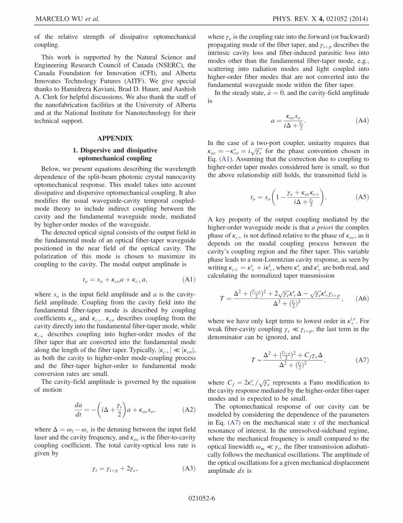
The influence of the derivatives of the optical resonanceis depicted in Figs. 5(a)–5(c). The derivatives with Cf ¼ 0are plotted in Fig. 5(d) and scaled in Fig. 5(e). A fewobservations can be made. Our device is undercoupled;γe ≪ γi. Thus, the external dissipative coupling has a largerinfluence on the line shape due to the fact that the decayrate into the fiber is much smaller (γe ≈ 1 GHz) comparedto the cavity linewidth (γi ≈ 30 GHz). We can quantita-tively compare their magnitude by evaluating the peakamplitude of the derivatives [7]:
∂T∂Δ
����max
¼ dTdΔ
�Δ ¼ γt
2
�¼ ð1 − ToÞ
Qo
ωo; ðA12Þ
∂T∂γi
����max
¼ dTdγi
ðΔ ¼ 0Þ ¼ 4ð1 − ToÞQo
ωo; ðA13Þ
∂T∂γe
����max
¼ dTdγe
ðΔ ¼ 0Þ ¼ −8ToQo
ωo; ðA14Þ
where To ¼ γ2iþp=γ2t is the transmission at optical reso-
nance ωo and Qo ¼ ωo=γt is the optical quality factor.Because of small fiber-cavity coupling (To ≈ 1), a changein the fiber coupling has a larger influence on the trans-mission near resonance such that ∂T=∂γe dominates overthe other terms, as seen in Fig. 5(d). Hence, a small value ofge can have a greater effect on the change in transmissionthan large values of gi and gOM. With a single peak at zerodetuning for ∂T=∂γi and ∂T=∂γe, it is possible to exploitoptomechanics at resonance, provided that dissipativecoupling is stronger than dispersive. By careful mixingof the coupling rates, optomechanical cooling is alsopossible, at least in theory [30]. Cooling arises throughquantum noise interference between dispersive and dis-sipative couplings, with the best results occurring whenoperating with external dissipative coupling [7].
2. Power spectral density andthermomechanical calibration
The transduction of the resonator mechanical motion to aphotodetected electronic signal, the subsequent analysis ofthe electronic power spectral density, and the relationshipbetween this power spectral density and the optomechan-ical coupling coefficients of the device are given below.In the setup used here, a real-time electronic spectrumanalyzer (RSA) samples the time-varying voltage VðtÞ ¼VOMðtÞ þ VnðtÞ generated by a photoreceiver input withthe optical field transmitted through the fiber taper. For agiven input power Pi and operating wavelength λ, theoptomechanical contribution VOMðtÞ to this signal isgiven by
VOMðtÞ ¼ ηgtiPiT½λ; xðtÞ�; ðA15Þwhere gti is the photoreceiver transimpedance gain(40 000 V/W, assuming a 50-Ω load), and η accounts forloss between the detector and fiber-taper output. Technicalfluctuations VnðtÞ arise from optical, detector, and elec-tronic measurement noise.In general, the fiber-taper transmission T varies, depend-
ing on the general displacement x of the nanocavitymechanical resonator and the effect of x on the opticalresponse of the fiber-coupled nanocavity. Here, xðtÞdescribes the thermally driven fluctuations of the nano-cavity mechanical resonator. The device considered inthis paper is operating in the sideband-unresolved regime
−3 −2 −1 0 1 2 3
−16
−12
−8
−4
0
Am
plit
ud
e (a
.u.)
Detuning (∆/γt)
ΔωoOpt
ical
tran
smis
sion
Δγe
Wavelength
Δγi
(a) (b) (c)
(d)−3 −2 −1 0 1 2 3
0
× 180
× 100
gOMgegi
× 1
(e)
FIG. 5. Change in optical transmission due to (a) dispersive,(b) intrinsic dissipative, and (c) external dissipative optomechan-ical couplings, respectively. (d) Relative strength of the threecontributions: ∂T=∂Δ, ∂T=∂γi, and ∂T=∂γe. (e) Comparativestrength when contributions are brought to similar amplitudes.The Fano modification is omitted for display purposes.
DISSIPATIVE AND DISPERSIVE OPTOMECHANICS IN A … PHYS. REV. X 4, 021052 (2014)
021052-7
(ωm ≪ γt), where the nanocavity field can “follow” themechanical oscillations, allowing us to write
VOMðtÞ ¼ ηgtiPi
�To þ
dTðλÞdx
xðtÞ�: ðA16Þ
The RSA demodulates VðtÞ and outputs IQ time-seriesdata VIQðtÞ ¼ IðtÞ − iQðtÞ, where IðtÞ ¼ cosðωctÞVðtÞ �hðtÞ and QðtÞ ¼ sinðωctÞVðtÞ � hðtÞ. Here, ωc is thedemodulation frequency, and hðtÞ is a low-pass antialiasingfilter, whose span is determined by the sampling rate (up to40 MHz). The Fourier transform of the IQ data is relatedto the input spectrum by VIQðωÞ ¼ Vðωþ ωcÞHðωÞ. Notethat a scaling factor is built into HðωÞ to ensure thatjVIQðω − ωcÞj2 can be accurately treated as a single-sided(positive frequency) representation of the symmetrizedinput power spectrum.The two-sided power spectral density of the optome-
chanical contribution to the input signal is given by
SOMVV ðωÞ ¼ jVOMðωÞj2=Δt; ðA17Þ
whereΔt is the acquisition time of the RSA time series, andVðωÞ ¼ R
Δt0 dte−iωtVðtÞ. For clarity, the dc component is
ignored in the following analysis. Using Eq. (A16), SOMVVcan be related to the stochastically varying displacementxðtÞ of the nanocavity
SOMVV ðωÞ ¼�ηgtiPi
dTðλÞdx
�2 1
Δt
����Z
Δt
0
dte−iωtxðtÞ����2
ðA18Þ
¼ G2
Δt
ZΔt
0
dt0Z
Δt−t0
−t0dte−iωtx�ðt0 þ tÞxðt0Þ; ðA19Þ
where G ¼ ηgtiPidT=dx describes the detector and theoptomechanical response. The stationary nature of xðtÞ,i.e., hx�ðtþ t0ÞxðtÞi ¼ hx�ðt0Þxð0Þi for measurement timeΔt ≫ 2π=γm, allows us to write the above equation as
SOMVV ðωÞ ¼ G2
ZΔt
0
dt0e−iωt0 hx�ðtþ t0ÞxðtÞi; ðA20Þ
¼ G2ðλÞSxxðωÞ; ðA21Þ
where SxxðωÞ is the displacement-noise spectral densityof the mechanical resonator. The total single-sided powerspectral density measured by the RSA is
SVVðλ;ωÞ ¼ G2ðλÞSxxðωÞ þ SnVVðλ;ωÞ; ðA22Þ
where the contribution from the technical noise is labeledSnVVðλ;ωÞ. Note that the spectral density can also beexpressed as true power over a load resistance Z such thatSp ¼ SVV=Z in units of W/Hz or dBm/Hz.
The displacement noise of a thermally excited mechani-cal mode m can be derived from the fluctuation-dissipationtheorem [42] and is given by
SxxðωÞ ¼4kBTeωm
Qm
1
m½ðω2 − ω2mÞ2 þ ðωωm
QmÞ2� ; ðA23Þ
where kB is Boltzmann’s constant, Te ¼ 300 K for theexperiments conducted here, and m is the effective massas defined in Ref. [36]. On mechanical resonance ω ¼ ωm,the power spectral density becomes
SVVðλÞjω¼ωm¼ G2ðλÞ 4x
2rmsQm
ωmþ SnVVðλÞ; ðA24Þ
where xrms ¼ hx2i1=2 ¼ffiffiffiffiffiffiffiffiffiffiffiffiffiffiffiffiffiffiffiffiffiffikBTe=mω2
m
pis the mean thermal
displacement. In the work presented here, backactioneffects are not significant, and the mechanical parametersof the deviceQm andωm are independent of λ and Pi. Theseparameters can be extracted by fitting Eq. (A22) to themeasured spectrum for a given λ (usually chosen tomaximize SVV=SnVV).The dispersive and dissipative optomechanical coupling
coefficients gOM, gi, and ge can be extracted from theexperimental data by fitting the λ dependence of SVVðλ;ω ¼ωmÞ to Eq. (A24). The interplay between optomechanicalcoupling mechanisms, as well as the line shape of thenanocavity optical resonance, is captured by GðλÞ via itsdependence on dT=dx, as described theoretically inEqs. (A8)–(A11).The noise-floor displacement resolution xNF of the
optomechanical transduction for a given set of operatingconditions can be determined from Eq. (A24), from whichthe displacement resolution can be calibrated. This method,widely employed by other researchers (see Ref. [43] andreferences therein), is used to calibrate the y axis inFig. 3(b). The torque sensitivity is calculated based onthe on-resonance spectral signal and Eq. (2) in the maintext. It can also be theoretically calculated using theeffective moment of inertia Ieff ¼ r2meff , where r is thedistance from the axis of rotation to the position ofmaximum displacement, and the thermally limited torquesensitivity τth ¼
ffiffiffiffiffiffiffiffiffiffiffiffiffiffiffiffiffiffiffiffiffiffiffiffiffiffiffiffiffiffiffiffiffiffi4kBTewmIeff=Qm
p. Both methods arrive
at the same result.
3. Numerical simulations ofoptomechanical coupling
Numerical simulations are performed to predict thedispersive gOM and dissipative internal gi optomechanicalcoupling coefficients for each of the mechanical modes ofthe split-beam nanocavity. In addition to predicting gOM ofthe torsionally actuated Tz mechanical mode of the split-beam nanocavity, these simulations assess the effect on theoptomechanical coupling of fabrication imperfections andthe presence of the optical fiber taper in the nanocavity near
MARCELO WU et al. PHYS. REV. X 4, 021052 (2014)
021052-8
field. All simulations are performed using COMSOL finite-element software to calculate the mechanical and opticalmode field distributions and properties ωo, ωm, m, and γi.Dispersive optomechanical coupling coefficients gOM arecalculated using perturbation theory, as by Eichenfield et al.[36], and directly from gOM¼dωo=dx, where ωoðxÞ is theoptical mode frequency as a function of mechanical dis-placement x. Dissipative gi are calculated directly fromdγi=dx. Simulations are performed for a range of devicedimensions consistent with our observed fabricationtolerances.The in-plane motion of the Tz mode modulates the split-
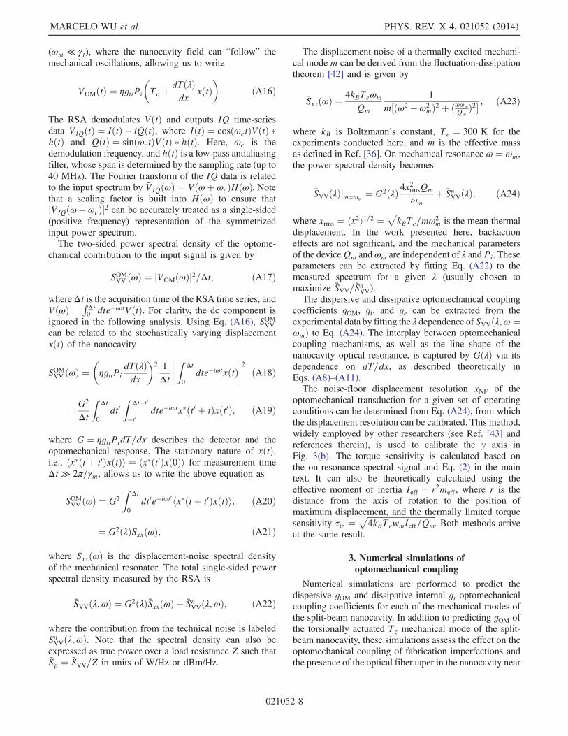
beam gap width d, resulting in a large dispersive opto-mechanical coupling. Figure 6(a) shows gOM for this modeas a function of an offset Δd away from the nominal valueof d ¼ 60 nm. For Δd ¼ 0, gOM ¼ −1.5 GHz=nm ispredicted, using both perturbation and direct dω=dx cal-culation techniques. If d is not optimized, small displace-ments of Tz will also modify γi. For our best estimate of thegap size, simulations predict gi ¼ 130 MHz=nm; however,within the uncertainty in position, this value can vary.Because of the different vertical symmetry of the nano-
cavity optical mode, and the displacement fields of out-of-plane modes Ty and C, their optomechanical couplingcoefficients gOM and gi are expected to be 0. However, thevertical symmetry of the optical mode is broken in twoways in the device studied here. Interactions between thenanocavity evanescent field and the optical fiber taper, forsmall fiber-taper height h above the nanocavity surface,modify the effective refractive index of the nanocavity. Thiseffect is described by an h-dependent gOMðhÞ that can reachthe GHz/nm range, as shown in Fig. 6(b). Fabricationimperfections in the device and the fabrication processcan also break vertical symmetry. Notably, offset bendingbetween the two mirrors can arise due to differentialinternal stresses in each beam and stiction forces due to
the proximity of the substrate. This is referred to as“sagging” in the discussion below. Figure 6(c) illustratesthe effect of sagging in the suspended mirror, resulting inan offset in the z direction with respect to the anchoredmirror. Broken vertical symmetry also manifests in nonzerointrinsic dissipative optomechanical coupling for the out-of-plane modes. Sagging of the suspended mirror shifts thenanocavity cavity mode away from the minimum intrinsicloss γi, resulting in gi ¼ dγi=dx < 0, as shown in Fig. 6(c).Numerical simulations for the fiber-cavity external
coupling coefficient ge are inconclusive. For typical valuesof ge ∼ 2 MHz=nm [32,33,39], the change in Qo for ourcavity (Qo ∼ 12 000) due to a change h of 100 nm wouldbe in the order ofΔQ ∼ 100, which is below the uncertaintyof our numerical simulations for this specific device.
[1] D. Rugar, R. Budakian, H. J. Mamin, and B.W. Chui, SingleSpin Detection by Magnetic Resonance Force Microscopy,Nature (London) 430, 329 (2004).
[2] O. Arcizet, P.-F. Cohadon, T. Briant, M. Pinard,A. Heidmann, J.-M. Mackowski, C. Michel, L. Pinard,O. Français, and L. Rousseau, High-Sensitivity OpticalMonitoring of a Micromechanical Resonator with aQuantum-Limited Optomechanical Sensor, Phys. Rev. Lett.97, 133601 (2006).
[3] M. Li, W. H. P. Pernice, and H. X. Tang, BroadbandAll-Photonic Transduction of Nanocantilevers, Nat. Nano-technol. 4, 377 (2009).
[4] G.Anetsberger,E.Gavartin,O.Arcizet,Q. P.Unterreithmeier,E.M. Weig, M. L. Gorodetsky, J. P. Kotthaus, and T. J.Kippenberg, Measuring Nanomechanical Motion with anImprecision below Standard Quantum Limit, Phys. Rev. A82, 061804 (2010).
[5] E. Gavartin, P. Verlot, and T. J. Kippenberg, A HybridOn-Chip Optomechanical Transducer for UltrasensitiveForce Measurements, Nat. Nanotechnol. 7, 509 (2012).
FIG. 6. Numerical simulation of the coefficients gOM and gi from finite-element simulations (COMSOL). The dashed line gOM data arecalculated directly from ωðxÞ. gi is calculated from γiðxÞ. All other data points are calculated perturbatively. (a) Dependence of gOM (leftaxis) and gi (right axis) of the torsional mode Tz on the variation in the gap size d. The shaded area corresponds to uncertainty in the gap(�5 nm) due to fabrication tolerances and scanning electron micrograph image resolution. (b) Fiber-induced dispersive optomechanicalcoupling coefficient gOM of the out-of-plane modes Ty and C. The shaded area indicates the uncertainty of the fiber height h. Larger gOMvalues at higher h are due to limited finite-element resolution. (c) Dependence of gOM (left axis) and gi (right axis) for out-of-planemodes on the vertical offset of the suspended mirror. The shaded area corresponds to a region of uncertainty (�25 nm) in the verticalposition of the suspended mirror due to postfabrication stresses and substrate effects.
DISSIPATIVE AND DISPERSIVE OPTOMECHANICS IN A … PHYS. REV. X 4, 021052 (2014)
021052-9
[6] X. Sun, J. Zhang, M. Poot, C. W. Wong, and H. X. Tang,Femtogram Doubly Clamped Nanomechanical ResonatorsEmbedded in a High-q Two-Dimensional Photonic CrystalNanocavity, Nano Lett. 12, 2299 (2012).
[7] A. G. Krause, M. Winger, T. D. Blasius, W. Lin, andO. Painter, A High-Resolution Microchip OptomechanicalAccelerometer, Nat. Photonics 6, 768 (2012).
[8] Y. Liu, H. Miao, V. Aksyuk, and K. Srinivasan, WideCantilever Stiffness Range Cavity Optomechanical Sensorsfor Atomic Force Microscopy, Opt. Express 20, 18268(2012).
[9] P. H. Kim, C. Doolin, B. D. Hauer, A. J. R. MacDonald,M. R. Freeman, P. E. Barclay, and J. P. Davis, NanoscaleTorsional Optomechanics, Appl. Phys. Lett. 102, 053102(2013).
[10] J. Abadie (LIGO Scientific Collaboration), A GravitationalWave Observatory Operating beyond the Quantum Shot-Noise Limit, Nat. Phys. 7, 962 (2011).
[11] D. M. Meekhof, C. Monroe, B. E. King, W.M. Itano,and D. J. Wineland, Generation of Nonclassical MotionalStates of a Trapped Atom, Phys. Rev. Lett. 76, 1796(1996).
[12] W. Marshall, C. Simon, R. Penrose, and D. Bouwmeester,Towards Quantum Superpositions of a Mirror, Phys. Rev.Lett. 91, 130401 (2003).
[13] J. Chan, T. P. Mayer Alegre, A. H. Safavi-Naeini, J. T. Hill,A. Krause, S. Groblacher, M. Aspelmeyer, and O. Painter,Laser Cooling of a Nanomechanical Oscillator intoIts Quantum Ground State, Nature (London) 478, 89(2011).
[14] J. D. Teufel, T. Donner, D. Li, J. W. Harlow, M. S. Allman,K. Cicak, A. J. Sirois, J. D. Whittaker, K. W. Lehnert, andR.W. Simmonds, Sideband Cooling of MicromechanicalMotion to the Quantum Ground State, Nature (London) 475,359 (2011).
[15] M. Aspelmeyer, T. Kippenberg, and C. Marquardt, CavityOptomechanics, arXiv:1303.0733.
[16] M. Eichenfield, J. Chan, R. M. Camacho, K. J. Vahala, andO. Painter, Optomechanical Crystals, Nature (London) 462,78 (2009).
[17] E. Gavartin, R. Braive, I. Sagnes, O. Arcizet, A. Beveratos,T. J. Kippenberg, and I. Robert-Philip, OptomechanicalCoupling in a Two-Dimensional Photonic Crystal DefectCavity, Phys. Rev. Lett. 106, 203902 (2011).
[18] A. H. Safavi-Naeini, J. Chan, J. T. Hill, T. P. Mayer Alegre,A. Krause, and O. Painter, Observation of Quantum Motionof a Nanomechanical Resonator, Phys. Rev. Lett. 108,033602 (2012).
[19] A. H. Safavi-Naeini, S. Groblacher, J. T. Hill, J. Chan, M.Aspelmeyer, and O. Painter, Squeezed Light from a SiliconMicromechanical Resonator, Nature (London) 500, 185(2013).
[20] S. Weis, R. Rivière, S. Deléglise, E. Gavartin, O. Arcizet,A. Schliesser, and T. J. Kippenberg, OptomechanicallyInduced Transparency, Science 330, 1520 (2010).
[21] A. H. Safavi-Naeini, T. P. M.Alegre, J. Chan,M. Eichenfield,M. Winger, Q. Lin, J. T. Hill, D. E. Chang, and O. Painter,Electromagnetically Induced Transparency and SlowLight with Optomechanics, Nature (London) 472, 69(2011).
[22] J. P. Davis, D. Vick, D. C. Fortin, J. A. J. Burgess, W. K.Hiebert, and M. R. Freeman, Nanotorsional ResonatorTorque Magnetometry, Appl. Phys. Lett. 96, 072513 (2010).
[23] J. A. J. Burgess, A. E. Fraser, F. Fani Sani, D. Vick, B. D.Hauer, J. P. Davis, and M. R. Freeman, QuantitativeMagneto-mechanical Detection and Control of theBarkhausen Effect, Science 339, 1051 (2013).
[24] A. C. Bleszynski-Jayich, W. E. Shanks, B. Peadecerf, E.Ginossar, F. von Oppen, L. Glazman, and J. G. E. Harris,Persistent Currents in Normal Metal Rings, Science 326,272 (2009).
[25] A. M. Yao and M. J. Padget, Orbital Angular Momentum:Origins, Behavior and Applications, Adv. Opt. Photonics 3,161 (2011).
[26] S. Forstner, S. Prams, J. Knittel, E. D. van Ooijen, J. D.Swaim, G. I. Harris, A. Szorkovszky, W. P. Bowen, and H.Rubinsztein-Dunlop, Cavity Optomechanical Magnetom-eter, Phys. Rev. Lett. 108, 120801 (2012).
[27] F. Elste, S. M. Girvin, and A. A. Clerk, Quantum NoiseInterference and Backaction Cooling in Cavity Nanome-chanics, Phys. Rev. Lett. 102, 207209 (2009).
[28] S. Huang and G. S. Agarwal, Reactive Coupling Can Beatthe Motional Quantum Limit of Nanowaveguides Coupledto a Microdisk Resonator, Phys. Rev. A 82, 033811 (2010).
[29] A. Xuereb, R. Schnabel, and K. Hammerer, DissipativeOptomechanics in a Michelson-Sagnac Interferometer,Phys. Rev. Lett. 107, 213604 (2011).
[30] T. Weiss and A. Nunnenkamp, Quantum Limit of LaserCooling in Dispersively and Dissipatively Coupled Opto-mechanical Systems, Phys. Rev. A 88, 023850 (2013).
[31] S. P. Tarabrin, H. Kaufer, F. Y. Khalili, R. Schnabel, and K.Hammerer, Anomalous Dynamic Backaction in Interfer-omters, Phys. Rev. A 88, 023809 (2013).
[32] M. Li, W. H. P. Pernice, and H. X. Tang, Reactive CavityOptical Force on Microdisk-Coupled NanomechanicalBeam Waveguides, Phys. Rev. Lett. 103, 223901 (2009).
[33] G. Anetsberger, E. M. Weig, J. P. Kotthaus, and T. J.Kippenberg, Cavity Optomechanicsand Cooling Nanome-chanical Oscillators Using Microresonator EnhancedEvanescent Near-Field Coupling, C.R. Phys. 12, 800(2011).
[34] A. Hryciw and P. E. Barclay, Optical Design of Split-BeamPhotonic Crystal Nanocavities, Opt. Lett. 38, 1612 (2013).
[35] P. B. Deotare, M.W. McCutcheon, I. W. Frank, M. Khan,and M. Lončar, High Quality Factor Photonic CrystalNanobeam Cavities, Appl. Phys. Lett. 94, 121106 (2009).
[36] M. Eichenfield, J. Chan, A. H. Safavi-Naeini, K. J. Vahala,and O. Painter,Modeling Dispersive Coupling and Losses ofLocalized Optical and Mechanical Modes in Optomechan-ical Crystals, Opt. Express 17, 20078 (2009).
[37] C. P. Michael, M. Borselli, T. J. Johnson, C. Chrystala, andO. Painter, An Optical Fiber-Taper Probe for Wafer-ScaleMicrophotonic Device Characterization, Opt. Express 15,4745 (2007).
[38] S. Groblacher, J. Hill, A. Safavi-Naeini, J. Chan, and O.Painter, Highly Efficient Coupling from an Optical Fiber toa Nanoscale Silicon Optomechanical Cavity, Appl. Phys.Lett. 103, 181104 (2013).
[39] K. Srinivasan, P. E. Barclay, M. Borselli, and O. Painter,Optical-Fiber Based Measurement of an Ultra-small
MARCELO WU et al. PHYS. REV. X 4, 021052 (2014)
021052-10
Volume High-q Photonic Crystal Microcavity, Phys. Rev. B70, 081306(R) (2004).
[40] J. Lipfert, J. W. J. Kerssemakers, T. Jager, and N. H. Dekker,Magnetic Torque Tweezers: Measuring Torsional Stiffnessin DNA and RECA-DNA Filaments, Nat. Methods 7, 977(2010).
[41] S. Forstner, J. Knittel, E. Sheridan, J. D. Swaim, H.Rubinsztein-Dunlop, and W. P. Bowen, Sensitivity and
Performance of Cavity Optomechanical Field Sensors,Photonic Sensors 2, 259 (2012).
[42] A. N. Cleland and M. L. Roukes, Noise Processes in Nano-mechanical Resonators, J. Appl. Phys. 92, 2758 (2002).
[43] B. D. Hauer, C. Doolin, K. S. D. Beach, and J. P. Davis,A General Procedure for Thermomechanical Calibrationof Nano/Micro-mechanical Resonators, Ann. Phys.(Amsterdam) 339, 181 (2013).
DISSIPATIVE AND DISPERSIVE OPTOMECHANICS IN A … PHYS. REV. X 4, 021052 (2014)
021052-11


![arXiv:2004.10451v2 [physics.optics] 30 Apr 2020 · 2020-05-01 · Linear analytical approach to dispersive, external and intrinsic dissipative couplings in optomechanical systems](https://img.dokumen.tips/doc/110x75/5f01fb657e708231d401fded/arxiv200410451v2-30-apr-2020-2020-05-01-linear-analytical-approach-to-dispersive.jpg)

![Linearly implicit schemes for a class of dispersive–dissipative systems€¦ · · 2017-08-29Mathematics Subject ... D(L ),andD(LL ) is dense in H.SeeKato[12, Chap. V, Sect. 3.8]](https://img.dokumen.tips/doc/110x75/5b0d3e247f8b9a02508d6197/linearly-implicit-schemes-for-a-class-of-dispersivedissipative-systems-subject.jpg)