Embed Size (px)
Citation preview

1
Study and Development of Thermoacoustic Devices
Hadi Babaei
Supervised by : Dr. Kamran Siddiqui
April 6, 2009
PhD Seminar

2
What is thermoacoustics ?Heat energy Sound energy
Fundamentals of Thermoacoustics
Engine
Refrigerator
Main components of a thermoacoustic device:
Resonator tube
Stack
Heat exchangers
Acoustic source (e.g. loud speaker)
Thermoacoustic engines: converting heat energy to sound energy
Thermoacoustic refrigerators: Utilizing sound energy to transfer heat
Schematic of a thermoacoustic device

3
Thermoacoustic Engine
Schematic of a thermoacoustic engine
-Thermoacoustic Engines convert heat energy (Qh) to sound energy (E2).
-Heat energy (Qh) is provided through the hot heat exchanger (HXh).
-Conversion of heat energy (Qh) to sound energy (E2) takes place inside the stack.
-The remaining heat energy (Qa,eng) is transferred to the outside environment
throughout the ambient heat exchanger (HXa,eng).

4
Schematic of a acoustically-driven thermoacoustic refrigerator
Acoustically-Driven Thermoacoustic Refrigerator
-Acoustically-driven thermoacoustic refrigerators transfer heat (Qc) from a
low temp. reservoir (HXc) to a high temp. reservoir (HXa,ref) by using
acoustic power provided by a loudspeaker (E2) .
-The heat transfer from a cold medium to a warm medium takes place inside
the stack.

5
Thermoacoustically-driven thermoacoustic refrigerator (TADTAR) :
Engine Refrigerator
Schematic of a thermoacoustically-driven thermoacoustic refrigerator
-Heat energy is converted to sound energy by a thermoacoustic engine.
-The produced sound energy is used to run a thermoacoustic refrigerator.
Heat energy Sound energy Cooling power

6
(i) At most one moving part (a loudspeaker) with no sliding seals
(ii) Nontoxic and environmentally friendly working gases
(iii) Low fabrication and maintenance cost
(iv) Utilizing any source of heat energy for cooling purposes (in a TADTAR)
(v) Generating electricity via a linear alternator or other electroacoustic power transducer
(vi) Flexible dimensions
Advantages of thermoacoustic devices

7
From a miniature thermoacoustic refrigerator with the length of about an inch, to
a thermoacoustic refrigerator for natural gas liquefaction with the capacity of 7 kw of
cooling power.
The thermoacoustic natural gas liquefier developed in Los Alamos National Laboratory
by Swift et el.(2002)
Applications
Covering a broad range of application:
The solar-powered TADTAR developed in Naval Postgraduate School by Adeff and Hofler (2000)
Thermoacoustic device, Symko et al. (2006)

8
My Research Work:
1. Theoretical StudiesI. Designing and optimizing of thermoacoustic devices
II. Modifying the theoretical model of thermoacoustic couples
2. Experimental InvestigationsI. Measuring and studying acoustic and streaming velocity fields
using synchronized PIV technique in thermoacoustic couples
II. Measuring and studying the developed temperature fields at the two
sides of a thermoacoustic couple using thermocouples
3. Developing a prototypeI. Designing, developing and testing a unique thermoacoustic device

9Flow chart showing the design and optimization procedure for thermoacoustic devices
Input data such as:
-Working gas-Desired temperaturesof the heat exchangers-Desired cooling power
Optimized output data:
-Ref. stack length and position-Eng. stack length and position -Required heat input for the hotheat exchanger
-Cross sectional area of the tube
1. Theoretical StudiesI. Designing and optimizing of thermoacoustic devices
10
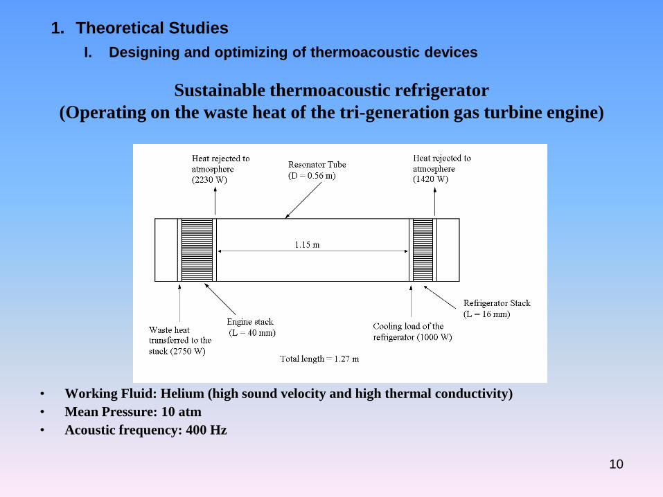
Sustainable thermoacoustic refrigerator(Operating on the waste heat of the tri-generation gas turbine engine)
• Working Fluid: Helium (high sound velocity and high thermal conductivity)• Mean Pressure: 10 atm• Acoustic frequency: 400 Hz
1. Theoretical StudiesI. Designing and optimizing of thermoacoustic devices

11
Sustainable thermoacoustic refrigerator(Operating on the waste heat of an automobile engine)
Working gas Helium
Mean pressure (kPa) 700
Frequency (Hz) 400
Cooling power (W) 30
Cooling temperature (˚C) 2
Ambient heat exchangers temperature (˚C) 27
Drive ratio (%) 3
Estimated required waste heat for engine (W) 159
Hot heat exchanger temperature (˚C) 260
Overall efficiency (%) 18.8
1. Theoretical StudiesI. Designing and optimizing of thermoacoustic devices

12
1. Theoretical StudiesII. Modifying the theoretical model of thermoacoustic couples
Steady-state temperature difference between the hot and cold ends of the stack versus stack position along the resonator at the pressure amplitude of 460 Pa, RVC is the stack material, comparing previous theoretical models, the present model and experimental results
Wheatley et al. model
Atchley et al. model
Developed model
Triangles: experimental results

13
2. Experimental InvestigationsI. Measuring and studying acoustic and streaming velocity fields using
synchronized PIV technique in thermoacoustic couples
Schematic of the experimental set-up for acoustic and streaming investigations Plexigalss stack
30-ppi RVC stack

14Simultaneously obtained velocity fields in the presence of the plexiglass stack at the peak pressure amplitude
of 628 Pa and the frequency of 146 Hz, (a) acoustic velocity field (b) streaming velocity field
(a) (b)

15
Resonator tube, 30-ppi RVC stack and heat exchangers
Air heater, control cube, flow switch and heat exchanger of the device
Air heater
Flow switch
Resonator tube RVC stackHeat exchangers
Developing a prototypeI. Designing, developing and testing a unique thermoacoustic device

16
1. Developed a comprehensive and systematic procedure to design and optimize
thermoacoustic device.
2. Modified the available theoretical model predicting the stack temperature
difference and validated the model by conducting experiments.
3. Investigation of the acoustic and streaming velocity fields using a novel
synchronization technique.
4. Design, development and performance testing of a sustainable thermoacoustic
device.
Conclusions:

17
Thank you

18Basic principles of thermoacoustic heat engines and refrigerators

19
Thermoacoustic couples (stacks):
Primary device that thermoacoustic phenomenon can be examined
Removing heat exchangers from a thermoacoustic refrigerator
Schematic of a thermoacoustic couple

20
Acoustic Streaming:
The streaming velocity is a second order flow induced by and superimposed on thedominant first-order acoustic velocity. The streaming patterns are almost stationary andtime invariant.
Schematic of the acoustic and streaming velocity fields
-In thermoacoustic engines and refrigerators, streaming generates mean motions
that result in an unwanted heat convection within the device.
-Streaming adds a heat load to the cold heat exchanger in a refrigerator or drives
away heat from the hot heat exchanger in an engine (causing a reduction in thermal
efficiency).
Schematic of the inner and outer streaming fields

21
Synchronized PIV technique:
-The measured velocity field inside a standing-wave resonator is the superposition ofacoustic and streaming velocities.
-Synchronized PIV technique allows us to measure streaming velocities in any spatialregion along the resonator
Acoustic and streaming velocity fields captured at a particular phase of the excitation signal, Nabavi et al. (2007)

22
Energy saving by TADTAR(theoretical prediction)
TADTARs have the potential to reduce the fuel consumption and
reduce the emission of harmful CFC refrigerants.
If all the industrial waste heat above 140ºC in the Netherlands can be
used in TADTARs, this would save 16 PJ yearly. This corresponds to
more than 5 billion m3 of natural gas (http://www.ecn.nl/en/).