Embed Size (px)
Citation preview

DISPLAYSKIN:
DESIGN AND EVALUATION
OF A POSE-AWARE WRIST-WORN DEVICE
By
Paul Robert Strohmeier
A thesis submitted to the School of Computing
In conformity with the requirements for
the degree of Master of Science
Queen’s University
Kingston, Ontario, Canada
July 2015
Copyright © Paul Robert Strohmeier, 2015

ii
Abstract
The recent surge in wrist-worn devices has stirred an increasing interest in wearable technology,
however, reactions to these devices are split and the use-case of these devices is still unclear. This
thesis explores affordances and opportunities offered by wrist-worn devices through the design
and implementation of DisplaySkin.
We approach the topic of wrist-worn displays by initially presenting a historical analysis of the
development of the wristwatch. Based upon this analysis we present a series of design guidelines:
we suggest that wrist-worn devices should be designed for non-focal attention, supply the user
with contextual information, accommodate glance based interactions and consider the user’s body
pose.
Implementing these guidelines, we built DisplaySkin, a wrist-worn, pose aware device.
DisplaySkin features a large flexible electrophoretic display and advanced sensing capabilities,
allowing it to orient content towards the users face, independently of their body-pose. This design
approach takes both new technological opportunities, as well as the cultural history of the
wristwatch into account.
To evaluate DisplaySkin, we conducted two experimental studies. The first study investigates the
effects of display size on a scrolling task, demonstrating that, even if the input area is kept
constant, users are able to complete tasks faster using a larger display. In our second experiment
we investigate the pose-aware display, demonstrating that using a pose-aware display improves
reaction times when acknowledging notifications on a wrist-worn display.

iii
DisplaySkin in various Application Scenarios:

iv
Co-Authorship
The experimental evaluations on pages 46 – 60 and 68 – 72
were conducted collaboratively with Jesse Burstyn.

v
Dedications
I wish to dedicate this work to my grandfather, Reverend Robert D. Keel.
His teaching will always stay with me. Rifle, Ring & Cross.
I wish to thank my family: my grandmother, Patricia for her wit and spirit, my father, Gerhard, for
teaching me to form my own opinion, my mother, Hillary, for teaching me to re-invent myself and my
sister, Sophie, for teaching me more things than I could ever enumerate.

vi
Preface
In June 2013 I first wrapped a display around my wrist. This was not long after the Pebble
smartwatch started shipping. Samsung had not yet announced Galaxy Gear and the Apple Watch
was not even a rumor yet. In many ways DisplaySkin is first of its kind: as of now there is no
other device with its display-configuration and tracking abilities.
Whenever one sets out to do something which has not been done before, collateral knowledge is
collected. The goal of this project was to build and evaluate a prototype wearable device. In doing
so, however, I more or less stumbled upon themes as varied as the history of time telling devices,
novel rapid prototyping methods and sensor design and implementation. While I did not expect
to be exploring these themes, they ended up as part of the contribution I make with my thesis.
Doing work which pushes boundaries is only possible in an environment rich with tacit knowledge
and practices. DisplaySkin was made possible by Jesse Burstyn’s prior work with David Holman
on prototyping with E Ink technology. Also, my experience working on PaperTab under Aneesh
Tarun’s supervision was invaluable. The Human Media Lab set the context from which this work
could emerge. I would like to thank Audrey, Conner, David, Aneesh, John, Marty, Antonio, Peng,
Joy and Jordan who all helped shape this environment. Finally thank you to Roel Vertegaal, for
creating this inspiring environment, filled with talented people. I would also like to thank Roel
for the opportunities and guidance he has provided me with, and for sharing his vision on this
project and the other exciting work we have done together.
My thesis follows the path I took together with Jesse Burstyn in developing DisplaySkin. His
work ethos, knowledge and willingness to discuss things in detail were invaluable to this work.
Without him this project would not have been possible. Thanks also goes to Nicholas Fellion,
who documented the process with pictures and video.
I also wish to thank Mélodie Vidal and Juan Pablo Carrascal for their time and patience in
proofreading my work and holding my hand through the process of manifesting my thoughts into
words, sentences and eventually this thesis.

vii
Table of Contents
Abstract ........................................................................................................................................................ ii
Co-Authorship ............................................................................................................................................ iv
Dedications................................................................................................................................................... v
Preface ......................................................................................................................................................... vi
List of Figures .............................................................................................................................................. x
List of Tables ............................................................................................................................................. xii
Glossary .................................................................................................................................................... xiii
Chapter 1 Introduction ............................................................................................................................... 1
1.1 Contextual interfaces with a cultural heritage ..................................................................................... 1
1.2 Introducing the Smartwatch ................................................................................................................ 3
1.3 The wrist-watch as a glance-based interface ....................................................................................... 4
1.4 Contributions....................................................................................................................................... 4
Chapter 2 History and Related Work ....................................................................................................... 7
2.1 Introduction ......................................................................................................................................... 7
2.2 The History of the Wristwatch ............................................................................................................ 8
The Mainspring ............................................................................................................................ 9
Drum Watches ............................................................................................................................. 9
The Bracelet Watch and Other Fashion Technology ................................................................. 11
The Wristwatch .......................................................................................................................... 14
History of the Wristwatch: Conclusion ...................................................................................... 16
2.3 The Digital Watch ............................................................................................................................. 16
Ornamental Devices ................................................................................................................... 17
New concepts introduced with the digital watch ....................................................................... 18
Expanding the functionality of the digital watch ....................................................................... 20
Current SmartWatches ............................................................................................................... 21
The Digital Watch: Conclusion .................................................................................................. 22
2.4 Enabling Technologies ...................................................................................................................... 22
Flexible Displays........................................................................................................................ 23
Thinfilm solid state batteries ...................................................................................................... 25
2.5 Contemporary Research .................................................................................................................... 27
Input Methods ............................................................................................................................ 27
Infrared Sensors ......................................................................................................................... 32

viii
Output Methods ......................................................................................................................... 32
Display Sizes & Configurations ................................................................................................. 33
Integrating body and device ....................................................................................................... 34
Placement of and Access to Mobile Technology ....................................................................... 34
Head Mounted Displays ............................................................................................................. 35
2.6 Conclusion ........................................................................................................................................ 36
Chapter 3 Building DisplaySkin, Evaluating Viewport Sizes ............................................................... 37
3.1 Implementation ................................................................................................................................. 37
Technologies Used in DisplaySkin ............................................................................................ 38
Assembling the Display ............................................................................................................. 39
Designing the Touch Sensor ...................................................................................................... 42
3.2 Evaluating the Effects of Different Display Sizes ............................................................................ 45
Experimental Motivation ........................................................................................................... 46
Experiment ................................................................................................................................. 46
Results ........................................................................................................................................ 48
Discussion .................................................................................................................................. 50
Chapter 4 Pose Aware Display ................................................................................................................ 55
4.1 Concept ............................................................................................................................................. 55
Design Rationale for Wrist-Worn Devices ................................................................................ 56
The Pose Aware Display ............................................................................................................ 59
Building the Pose-Aware Display .............................................................................................. 59
4.2 Interaction Scenarios using DisplaySkin and a Pose-Aware Display ............................................... 65
Driving a Car .............................................................................................................................. 65
Preparing Food ........................................................................................................................... 66
Using DisplaySkin to Augment Sports ...................................................................................... 66
Supporting Musicians ................................................................................................................ 67
4.3 Evaluating the Pose-Aware Display ................................................................................................. 68
Experiment ................................................................................................................................. 68
Results ........................................................................................................................................ 72
Discussion .................................................................................................................................. 73
4.4 Concluding thoughts to the Pose-Aware display .............................................................................. 75
Chapter 5 Limitations, Future Scenarios & Conclusion ....................................................................... 77
5.1 Future Work ...................................................................................................................................... 77
Ornamental use of DisplaySkin ................................................................................................. 77

ix
Separation of Public and Private viewing areas ......................................................................... 78
Removing the device .................................................................................................................. 78
Skin ............................................................................................................................................ 79
5.2 Current Limitations ........................................................................................................................... 80
5.3 Conclusion ........................................................................................................................................ 80
References .................................................................................................................................................. 83
Appendix .................................................................................................................................................... 93

x
List of Figures
Figure 1.1 – Sherlock accessing contextual information .............................................................................. 1
Figure 1.2 – Sony Smartwatch displaying contextual information: Time and Weather ............................... 2
Figure 1.3 – Schematic overview of DisplaySkin ......................................................................................... 5
Figure 2.1 – Mainspring ................................................................................................................................ 9
Figure 2.2 – Drum Watch with Sundial by Schissler (ca. 1560) .................................................................. 9
Figure 2.3 – Portrait of Ulrich Ehringer holding a Drum Watch (ca. 1530) .............................................. 10
Figure 2.4 – The Fusee ............................................................................................................................... 11
Figure 2.5 – Skull Watch owned by Mary Queen of Scots (ca. 1585) ....................................................... 12
Figure 2.6 – Bracelet watch (left, ca. 1868) and watch embedded in ring, (right, ca. 1585) ..................... 13
Figure 2.7 – The 9th Bengal Lancers in India ca. 1897 and close up of wristlet. ....................................... 15
Figure 2.8 – Mappin & Webb advertisement, rtistic depiction of the 21st Lancers ................................... 15
Figure 2.9 – Pulsar Time Computer ........................................................................................................... 17
Figure 2.10 – 'Motherboards' of the Uranus (left) and a Pulsar Calculator Watch (right) ......................... 18
Figure 2.11 – Synchronar and Nepro Alfatronic ........................................................................................ 19
Figure 2.12 – Seiko Calculator Watch ....................................................................................................... 20
Figure 2.13 – Linux watch by Mann, OLED and LCD versions of Linux watch by IBM ......................... 20
Figure 2.14 – Samsung SPH-WP10 Phone Watch...................................................................................... 21
Figure 2.15 – Moto 360, LG G Watch, Samsung Gear Live, Apple Watch, Pebble Time ........................ 21
Figure 2.16 – LED display, bi-stable Gyricon beads, and magnetically actuated bus display. .................. 23
Figure 2.17 – PaperPhone, Snaplet and DisplayStacks.............................................................................. 24
Figure 2.18 – Color smartwatch mockup by PlasticLogic .......................................................................... 24
Figure 2.19 – Thinfilm, solid state, cell (left) and battery concept (right) ................................................. 26
Figure 2.23 – Wristwatch with segmented E Ink display, powered by thinfilm micro-energy cell ........... 26
Figure 2.24 – Touch Interface on Wristband by Funk et al ....................................................................... 28
Figure 2.25 – Principles of SideSight (left), device with capacitive touch on the edge............................. 28
Figure 2.26 – Skin manipulation around the device as input ...................................................................... 29
Figure 2.27 – Skin Buttons ........................................................................................................................ 29
Figure 2.28 – Mechanical input with 9 DOF .............................................................................................. 30
Figure 2.29 – Projection based prototype for string based interface ........................................................... 30
Figure 2.27 – Augmented forearm. ............................................................................................................ 33
Figure 2.31 – The arm as interaction and display surface........................................................................... 34

xi
Figure 2.32 – Loupe .................................................................................................................................... 35
Figure 3.1 – Flexible Plastic Logic Display, used in PaperTab ................................................................. 38
Figure 3.2 – Layers of Flexible display ..................................................................................................... 38
Figure 3.3 – Cutting the Flexible Display .................................................................................................. 39
Figure 3.4 – Inserting Flexible Display in 3D printed frame ..................................................................... 40
Figure 3.5 – Heat-Shaping the Display ...................................................................................................... 41
Figure 3.6 – DisplaySkin in its thermoformed resting state ........................................................................ 41
Figure 3.7 – Visualization of Data Reading ............................................................................................... 43
Figure 3.8 – Basic Components of IR sensing circuit ................................................................................. 44
Figure 3.9 – prototypes of linear IR multitouch sensor used with DisplaySkin ......................................... 45
Figure 3.10 - Small Display (left) and Cylindrical Display (right). ............................................................ 47
Figure 3.11 - Typical hand positions for different Display Sizes ............................................................... 52
Figure 4.1 – DisplaySkin with pose-aware contextual information ............................................................ 55
Figure 4.2 – Watch compared to the cluttered GUI of most applications .................................................. 57
Figure 4.3 – WristFlicker ........................................................................................................................... 60
Figure 4.4 – Infrared based pose detection ................................................................................................ 61
Figure 4.5 – Kinematic Model in foreground, Participant conducting experiment in background. ........... 62
Figure 4.6 – Pose aware display ................................................................................................................ 64
Figure 4.7 – Driving a car using DisplaySkin ............................................................................................. 65
Figure 4.8 – Preparing Food using DisplaySkin ......................................................................................... 66
Figure 4.9 – Playing Gold with DisplaySkin .............................................................................................. 67
Figure 4.10 – Displaying Guitar Chords on DisplaySkin ........................................................................... 67
Figure 4.11 – Participant being interrupted by notification. ....................................................................... 69
Figure 4.12 – Angles used in our experiment ............................................................................................. 70
Figure 5.1 – tago arc by Liber8 .................................................................................................................. 77
Figure 5.2 – Tattoo concept by Phillips, interactive makeup by Vega and photography by Baran ........... 79
Figure 5.3 – X Men’s Mystique transforming from an adopted skin into her own .................................... 80

xii
List of Tables
Table 3.1 – Targeting times in seconds and their standard deviations ........................................................ 49
Table 3.2 – Questionnaire Results .............................................................................................................. 50
Table 3.3 – Task completion times for target distance and display types in seconds ................................ 51
Table 4.1 – Homing and resume times and their standard deviations in seconds ...................................... 72
Table 4.2 – Advantage of pose-aware display for homing times in seconds .............................................. 73
Table 4.3 – Advantage of pose-aware display for resume times in seconds ............................................... 74

xiii
Glossary
Arduino
An Arduino is an open-source physical computing platform based on a prototyping board using
Atmel AVR microcontrollers, and a cross-platform development environment for writing
software for the board.
Bracelet Watch
Early wearable watches worn as jewelry by fine ladies during the Victorian times.
Catastrophic Failure
Catastrophic failure is a sudden and total failure from which recovery is impossible. The term is
usually used in structural engineering. Describing batteries it is used for technologies for which
minor damage does not merely lead to the battery failing, but to unstable conditions which can
cause damage to its environment.
Context
The circumstances or setting of an activity. The information required to fully understand and
assess what the user is currently engaged with. For example, if a user is in a location which they
have not been before, suggesting that the user does not know their way. If the user is walking
faster than usual, suggesting they are in a hurry. Awareness of the context of the primary activity
helps provide appropriate contextual information.
Contextual Information
Information which supports the user in accomplishing their primary activity. A user at an
unknown location might be able to accomplish their primary activity better with access to a map.
A user who is in a hurry might benefit from knowing how much time they have before their next
appointment.
Degrees of Freedom (DOF)
The number of sensory ‘dimensions’ measurable by a sensor, or a set of sensors. An accelerometer
for example, can usually sense acceleration in three directions, acceleration in directions not
directly measured can be inferred by the combined output of all three measurements. A gyroscope,
can traditionally measure rotation in three directions, any rotation which does not occur along one
xiv
of the defined axis can again be inferred by the combined sensor reading. Together the three
dimensional gyroscope and the three dimensional accelerometer have six degrees of freedom (6
DOF).
Do It Yourself (DIY)
‘DIY’ refers to methods of building, modifying or preparing something without requiring the
support of experts or professionals.
Focal Attention
Focal attention refers to a type of attention in which the individual is deliberately, consciously
focused on a certain thing to the exclusion of surrounding stimuli.
Glance-Based Interaction
Interactions which require nothing more of the user than to glance at an object. For example, the
speed dial on a car, can be read by merely glancing at it.
Inertial Measurement Unit (IMU)
An inertial measurement unit is a device that measures velocity, orientation, and gravitational
forces, using a combination of accelerometers, gyroscopes and magnetometers. IMUs are
typically used in aircrafts, and have become commonplace in DIY circles, as they are an integral
part required for flying most hobby aircrafts.
(Near) Infrared
Infrared (IR) is electromagnetic radiation with wavelength longer than that of visible light. Near
infrared is the part of the IR spectrum closest to visible light, in terms of sensor design IR usually
refers to frequencies between 780nm and 1500nm
Interaction area
The physical space which the user can take advantage of when interacting with a device. The
interaction area of a trackpad is confined to its physical dimensions, while the interaction area of
a mouse extends as far as the arm can reach.

xv
Kinematic Model
A kinematic model is a mechanical model describing the motion of points and rigid bodies.
Mainspring & Fusee
The mainspring is a spiral torsion spring which powers mobile mechanical devices. The fuse is a
mechanical system which enables the force of the mainspring to be constant.
Primary Activity
The activity which has the users focus. For example, a user might be searching for a building in
a foreign city. The user is engaged in multiple activities, such as walking, avoiding other
pedestrians or stopping at red traffic lights. The users primary activity is searching for the address,
while the other activities described happen automatically without requiring the user to explicitly
attend to them.
Pose-Aware Display
A display which is aware of the user’s body pose relative to itself. This information is used to
orient content appropriately. The auto-rotate function of most mobile devices could be considered
a crude version of a pose aware display.
Projection
When speaking of a projected touch surface, we are comparing the sensor to a projector. It can be
imagine like a simplified projector with an integrated camera. The sensor ‘projector’ emits light
onto a projection area. When that projected area is touched, light is reflected back into the sensors
‘camera’. The sensor can therefore turn any surface into a projected touch screen, as long as there
is a line of sight.
Proprioception
Proprioception is the sense of our own body: the sense of the relative position of neighbouring
parts of our body and strength of effort being employed in movement
Static Display
A display which displays content without adjusting it to the user’s perspective. Static in this
context refers to the displays orientation, not the content which is being displayed.
Thermoforming

xvi
Thermoforming is a manufacturing process where a plastic material is heated to a temperature at
which it becomes pliable and then formed into its desired shape.
Touch resolution
The precision with which a touch sensor can measure the position of a finger. High touch
resolution means that the sensor can detect detailed analog movements, as we are used to from
capacitive touch sensors, while low touch resolution only allows discrete input, for example to
input numbers on a number-dial.
Viewport
The viewport is the active area on a display through which one can view a document or
application. For example, when browsing a website, one can adjust the viewport size, by changing
the size of the browser window.
Wristlet
A predecessor of the wristwatch. Usually custom-made, these consisted of a pocket-watch secured
within a leather strop which wrapped around the wrist.

1
Chapter 1
Introduction
1.1 Contextual interfaces with a cultural heritage
In the 1887 novel ‘A study in Scarlett’, Sherlock Holmes identifies that Dr. Watson’s sibling is a
drunk, based on a scratch pattern he finds on Dr.Watson’s watch [31] [89]. In the first episode of
the 2010 TV show Sherlock, ‘A study in Pink’, Holmes makes the same inference based on a
scratch pattern he finds on Dr.Watson’s phone [118]. This example highlights that even though a
device may use a completely new technology, its social and cultural significance may remain
preserved. In the BBC’s modernized adoption of Sherlock Holmes, replacing the plot device of the
watch with a mobile phone maintains the internal logic of the narrative [119].
Figure 1.1 – Sherlock accessing contextual information, such as the weather at different locations,
using a smartphone [89]
This is not the only time that the TV show uses a mobile phone as a plot device. In fact, they are
ubiquitous throughout the show. It is interesting that, while mobile phones play a recurring role,
they are hardly ever used for making telephone conversations. Instead they are used to check the
weather, check a timetable, look up something on the internet etc.: the main use of the smartphone,
2
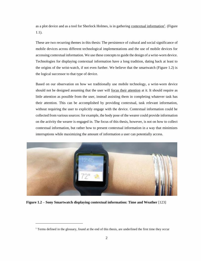
as a plot device and as a tool for Sherlock Holmes, is in gathering contextual information1. (Figure
1.1).
These are two recurring themes in this thesis: The persistence of cultural and social significance of
mobile devices across different technological implementations and the use of mobile devices for
accessing contextual information. We use these concepts to guide the design of a wrist-worn device.
Technologies for displaying contextual information have a long tradition, dating back at least to
the origins of the wrist-watch, if not even further. We believe that the smartwatch (Figure 1.2) is
the logical successor to that type of device.
Based on our observation on how we traditionally use mobile technology, a wrist-worn device
should not be designed assuming that the user will focus their attention at it. It should require as
little attention as possible from the user, instead assisting them in completing whatever task has
their attention. This can be accomplished by providing contextual, task relevant information,
without requiring the user to explicitly engage with the device. Contextual information could be
collected from various sources: for example, the body pose of the wearer could provide information
on the activity the wearer is engaged in. The focus of this thesis, however, is not on how to collect
contextual information, but rather how to present contextual information in a way that minimizes
interruptions while maximizing the amount of information a user can potentially access.
Figure 1.2 – Sony Smartwatch displaying contextual information: Time and Weather [123]
1 Terms defined in the glossary, found at the end of this thesis, are underlined the first time they occur

3
1.2 Introducing the Smartwatch
The reason for focusing our research on wrist worn device is best demonstrated through the 2012
Gizmodo review of the Sony SmartWatch [123]. It is representative of the general attitude towards
smartwatches which we observed when we first started working on our own prototypes. The
concept of a lightweight interactive device that is worn on the arm appears appealing. Gizmodo’s
initial reaction to, for example, the Sony SmartWatch is euphoric:
“ […] a delightful new way to do smartphone things without a
smartphone. It could even look cool. Isn't this the kind of thing
we're all supposed to secretly (or not so secretly) lust after?”
However, things look quite different in practice. Once they actually test it, the Gizmodo team is
quite disappointed. They find the interface clunky, they find touch input on such a small display
cumbersome and they find that it is generally not a device they would want to use. The conclusion
to their review is sobering:
“[The] SmartWatch is pathetic, frustrating, and empty.”
In the past few years, companies such as Apple, Google and Samsung as well as some new startups,
most notably Pebble, have targeted the smartwatch market. In May 2012 Pebble’s first Kickstarter
campaign to collect funding for producing a smartwatch received over $10,000,000, setting the
record for the best funded Kickstarter campaign ever [139]. Pebble launched a second Kickstarter
campaign in 2015 for the third generation of their smartwatch attracting $9,000,000 within under
24 hours, and eventually breaking their previous record [64, 102]. Clearly there is a large public
interest in this type of technology.
What makes the smartwatch such an appealing idea and why is it so difficult to get right? We
believe that it is the great cultural heritage of wrist worn devices that is responsible for both the
appeal of smartwatches, as well as many of the problems with their implementation. In this thesis
we explore what we can learn from the history of wearables and where we should break from the
traditions surrounding wristwatches. In this thesis we combine a historical analysis of the
wristwatch with hardware and implementation considerations as well as theoretical considerations
for designing interactions on wrist-worn devices.

4
1.3 The wrist-watch as a glance-based interface
The recent introduction of the Apple Watch has highlighted a design issue which warrants further
investigation. Apple states that their watch is an excellent time-telling device [7]:
“You’ll still be able to do with Apple Watch what you do with
your current watch: tell the time (and if you want, the date) at a
glance and trust that it’s accurate.”
This very basic feature – telling the time at a glance – is something the Apple Watch, and similar
smartwatches are actually surprisingly poor at: to preserve battery time, the Apple Watch turns its
display off by default. The Apple Watch is activated for 6 seconds if the arm is placed in a ‘time
telling’ pose, alternatively one can tap the watch to activate it for 17 seconds. This makes it difficult
to casually glance at ones smartwatch and tell the time without actively engaging with it [140, 155].
Apple Blogger John Gruber notes several situations in which the Apple Watch, as a time-telling
device, did not meet his expectations. This includes having coffee with a friend before an important
appointment: towards the time he needed to leave, he would start glancing at his watch, so as to
spend as much time as possible with his friend, while arriving in time for his appointment. Using
the Apple Watch, Gruber was either required to artificially flick his wrist or activate the Watch
with his other hand – a far heavier gesture than he was comfortable with. Other scenarios, which
he found were no longer possible using the Apple Watch, were casually timing processes while
cooking, or checking the time during activities which occupy his hands [140].
These observations point out an important quality of the traditional wristwatch: its content is
accessible at a glance. In essence Gruber [140] and others [155] criticise the Apple Watch, because
it requires a level of engagement higher than what they were expecting based on their experiences
with traditional wristwatches. This points out that even the newest generation of available wrist-
worn devices can benefit from further investigation into this design space.
1.4 Contributions
The core contribution of this thesis is DisplaySkin (Figure 1.3), a prototype wrist worn device with
a large cylindrical Electrophoretic Display. The structural elements of DisplaySkin were

5
manufactured in a custom process which involved 3D printing a frame which was subsequently
thermoformed. Its display is a 7.2” customized PlasticLogic electrophoretic display. This display
is augmented with a projected near infrared multi-touch sensor of our own design. There is a 9
degrees of freedom (DOF) inertial measurement unit (IMU) integrated in the device. This IMU is
used for creating a kinematic model of the users arm, enabling DisplaySkin to position content such
that it is in view of the user: if the user is viewing DisplaySkin from the top, information is
displayed around the 0° position, while, if the user views the display from the side (as the reader is
doing in figure 1.3) content is centered around the 90° position [19].
Figure 1.3 – Schematic overview of DisplaySkin
In this thesis, we use DisplaySkin to investigate issues related to the design of wrist-worn devices.
Our initial investigation is a focused exploration of the effects of display sizes on interaction. This
experiment was designed in reaction to design trends and interaction research surrounding wrist-
worn products. Specifically, most wrist-worn devices have adopted the form factors of traditional
wristwatches, resulting in a large body of interaction research dedicated to overcoming the
constraints in display sizes. We believe that this constraint is an anachronism, which we need not
limit ourselves to when designing wrist worn devices. In implementing our own prototype, we
demonstrate that alternative form factors are possible. We evaluate the effects of the alternative
display configuration by presenting the user with a list-scrolling task, and measuring task

6
completion times. We simulated different display sizes by modulating the viewport of DisplaySkin.
Our results indicate that larger displays do enable faster task completion. However, they also point
out that the type of task chosen does not fully take advantage of the cylindrical form factor of the
display and might not be the type of interaction a wrist worn device is best suited for.
Inspired by the results of our first experiment, by the history of wrist-worn devices and current
research into wearable devices, we present a set of design guidelines. These guidelines emphasize
the role of the smartwatch as supplementary devices: its role should be to support the user’s primary
activity. To do this effectively, it should not require the user’s focused attention, instead wrist-worn
devices should provide the user with supporting contextual information, while minimizing
interruptions to the task at hand.
Based on these guidelines, we designed and implemented the pose-aware display. A pose-aware
display has information of its position relative to the users face and adjusts information so that it is
displayed in view of the user and oriented for optimizing legibility. By tracking the users pose in
real time with an inertial measurement system we can adjust the placement and orientation of
content while the user is moving, maximizing the availability of information to the user. We
demonstrate the benefits of such a quasi ‘always available’ display by example of several
interaction scenarios. In addition to these qualitative examples, we also conduct a quantitative
evaluation of the pose-aware display. To better understand the benefits of a pose aware display, we
compare it to a static wrist-worn display in an experiment investigating task interruption times. We
find that users are significantly faster in reacting to a notification using the pose aware display than
using the static display.
In the course of building and designing DisplaySkin and the supporting technology enabling the
pose-aware display, we introduce novel prototyping methods and sensor designs. Like our
historical analysis, these more applied aspects of our work are intended to support other designers
in their own efforts and are part of the contribution of this thesis.

7
Chapter 2
History and Related Work
2.1 Introduction
The way we interact with digital technology is not only based on what the technology is capable
of, but also on user requirements. A given requirement can be fulfilled by different technologies.
For example, the Sumerian clay tablets and the printed book are very different technologies that
satisfy the same requirement: storing information2. We are currently witnessing a transition from
using devices we carry in our pockets, to devices we wear on our bodies. This transition is not as
novel as we might think – a similar technological shift occurred around the beginning of the 20th
century with the decline of the pocket watch and rise of the wristwatch. In this chapter, we will
take a historical look at this transition, as it can support the design of a new generation of wrist
worn devices. We suggest that the factors leading to the adoption of the wristwatch – the user
requirements that the wristwatch was better suited to fulfill than the pocket watch – are the same
today as they were then.
Recurring patterns in adopting technology can again be observed by comparing the digital watch
in the early 1970’s and the first drum watches in the 15th century. Similar parallels can be observed
comparing today’s smartwatches to the first wearable devices of the 16th century. The technology
behind the first digital watches also enables new form factors and approaches that foreshadow some
of the design recommendations we will make for future generations of smartwatches.
In the 15th century, the development of the mainspring and consequently the fusee enabled a whole
generation of mobile technology. We believe that current advances in display and power storage
technologies will have a similar enabling effect on the next generation of wearable devices. We
will briefly outline technologies which were important considerations for our own design. While
there is a large body of impressive prototyping work which relies on projection and simulation, we
find it important to work as close to the actual target media as possible. We believe that simulations
2 We realise this is a simplification of a complex subject matter, but appeal to the reader to except this
simplified example for the sake of our argument.

8
introduce their own unique constraints and affordances. Working with a physical prototype
provides us with a tacit understanding of the subject matter that is important for understanding how
a user will engage with the technology.
Contemporary research into wrist-worn devices appears to focus on the small size of their displays,
which make controlling them with touch interfaces unpractical. There is a large body of work,
focused on the size constraint of wrist worn interfaces, usually by means of expanding the
interaction area. While the traditional form factor of the wristwatch appears to be the go-to design
for most current wrist worn devices, we will highlight several design explorations aimed at
exploring alternative form factors and display sizes. After discussing output methods and display
configurations, we will introduce the concept of merging device and body, and discuss where on
the body we should be placing wearable displays.
2.2 The History of the Wristwatch
There are countless stories of the invention of the wristwatch. It appears as though just about every
watch-maker in the early 20th century claimed to have invented it. Jaquet and Chapuis mocked this
trend in their book ‘Technique and History of the Swiss watch’ [34]. They attributed the invention
of the wristwatch not to a watch maker, but to ‘naïve ingenuity’:
“[A] good woman [was] seated on a bench in a public park,
suckling her child. In order to observe the time, she had attached
her watch around her arm. A passer-by was struck by this naïve
ingenuity. On his return home, he soldered two lugs on to a lady's
watch, and added a strap.”
In fact, like most inventions, there is no single origin of the wristwatch. The wristwatch has a
tradition that dates much further back than the 20th century in which it became popular.

9
The Mainspring
Early time telling devices took advantage of diverse mechanisms to tell the time, including moving
shadows [26], flowing water or sand [106] and pendulums [17]. None of these time telling methods
were suited for mobile use, as they were either too large to conveniently transport or subject to
inertial forces which would make them inaccurate when transported [17].
A technological innovation that made the first portable watches possible is the mainspring (Figure
2.1). A mainspring is a spiral torsion spring. It is wound, usually with a key, to store force. The
stored force can be used to rotate a clockwork’s wheels as it unwinds. To this day, it is used to
power watches and other mechanical devices [17, 86, 109].
Figure 2.1 – Mainspring [71]
Drum Watches
The first mobile time-telling devices that made use of a mainspring had their origin in Nuremberg
around 1500 [92]. Nuremberg was a wealthy city and had a rich tradition of lock- smiths who found
that their skillset could also be applied to building mobile time-pieces.
Figure 2.2 - Drum Watch with Sundial by Schissler (ca. 1560) [92]

10
The primary function of these early pocket watches was ornamental. If someone wanted to tell the
time, they used a sun dial [17]. This is apparent in the drum-watch by Schissler (ca. 1560) which
has a sun dial on its back (Figure 2.2). The mechanical watch was not reliable in of itself: the sun-
dial at the back was required to correct the time of the mechanical watch. Its intricate gold-reliefs
are additional indicators that this watch was appreciated for its ornamental qualities [92]. Another
indicator of the ornamental qualities of these drum watches is evident in the practice of including
them in portraits, for example in the following portrait of Ulrich Ehringer by Christoph Amberger
(ca. 1530, figure 2.3) [17, 92].
Figure 2.3 - Portrait of Ulrich Ehringer holding a Drum Watch (ca. 1530) [92]
A problem with the mainspring is that its tension is not consistent. Therefore a watch powered by
a mainspring would initially go too fast, and as the mainspring unwound, gradually slow down.
Attempts were made to introduce a minute hand, but were not especially popular: due to the
idiosyncrasies of the mainspring, it was common for mechanical watches to be off by 30 minutes
or more, rendering the minute hand meaningless [17, 109].
A solution to this problem was introduced towards the end of the 16th century in the form of the
fusee (Figure 2.4). The fusee used a spiral winding to correct for the varying tension of the
mainspring. It lead to an appreciation of the minute hand and later even to the adoption of the
seconds hand. Other factors that helped improve the precision of the watch were brass mechanics

11
which were introduced about 1600. These had less friction and a better precision than the steel
components previously used [17, 109].
Figure 2.4 - The Fusee [29]
These innovations, however, did not change the culture and practices surrounding the telling of
time: ‘Real’ timekeeping was done by clocks in watch- and church-towers. At night, the watchmen
on patrol would additionally call out the hours (this, in fact, is also where the term ‘watch’ for a
time-keeping device stems from). These traditional systems were considered more useful than a
handmade and expensive watch [17].
In summary, the first mobile time telling pieces were adopted not because they were useful, but
because they were prestigious. Even once the technology had matured to a point that the pocket
watch could potentially be a useful tool, the traditions and practices surrounding time telling made
the idea of a pocket watch unappealing [17].
The Bracelet Watch and Other Fashion Technology
By the 16th century, watches had become an explicit fashion accessory. Mary Queen of Scots, for
example, owned a small watch, shaped like a skull (Figure 2.5), which she commonly wore. She
eventually presented the Skull Watch to her maid of honor, Mary Seton [17, 27, 87]. Other watches
were shaped as animals, insects or flowers [17].

12
Figure 2.5 – Skull Watch owned by Mary Queen of Scots (ca. 1585) [144]
At the court of Queen Elisabeth I, a watch was selected to match one’s outfit, just as one would
choose a suiting coat or hat. These watches were usually worn on a chain or ribbon around the neck
and were intended to be seen by others. A given watch usually came with multiple cases. The ladies
of court could remove the clockwork and place it into a case that suited their mood of the day.
These cases were decorated with jewels, bones, gold ornaments and enamel paintings [17].
In addition to the watch-jewel worn around the neck, watchmakers started embedding their pieces
into other objects such as bracelets and rings [53] (Figure 2.6). One of the earliest records of such
bracelet watches dates back to 1571 and was worn by Queen Elisabeth I. Another famous early
‘wristwatch’ is the bracelet watch Patek Phillippe manufactured for the Countess Koscowicz of
Hungary (Figure 2.6) [165].

13
Figure 2.6 Patek Phillippe’s bracelet watch (left, ca. 1868) [165] and watch embedded in ring,
conveniently doubling as a crucifix, by Jakob Weiss (right, ca. 1585) [53]
While there may have been a practical appeal of bracelet watches, the bracelet watch was still far
away from what was to become the wristwatch. For one, the bracelet watch was considered
effeminate which made it taboo for Victorian men to wear. There were also practical
considerations: the bracelet watch was not designed to be durable, making it unpractical as a
timepiece. Pocket watches were more robust and safely protected in the pouch of a waistcoat [17,
142]. Finally they were designed as lockets, and had to be opened for time telling. Figure 2.6 shows
both the bracelet watch and the watch-ring in their open states (the bracelet watch opens to the left,
when closed the watch-face would be covered by a large jewel), while the skull watch (Figure 2.5)
needs to be opened at the jaw to reveal the internal clockwork [144].
The first wearable devices were not adopted for any utilitarian purpose, but where explicitly used
as fashion items. The tradition of swapping the casing of watch, to make its appearance suit the
outfit one was wearing is somewhat reminiscent of the various decorative casings available for
most mobile smartphones. It is also similar in concept to the different styles of watchstraps
available for the Apple Watch which play an important factor in their marketing campaign.

14
The Wristwatch
It is towards the end of the 19th century that the wristwatch gained acceptance as a tool. With the
beginning of industrialization, watchmaking was no longer the painstaking labor of a single
talented individual. Instead, companies would manufacture specific parts in larger quantities. This
allowed the price of watches to drop and the quality of the devices to improve. Aviators, motorists
and hunters started to use wristwatches [17, 51] as they allowed them to tell the time without
disrupting their primary activity.
More importantly, new military strategies and technologies made precise coordinated timings a
necessity. This lead to a wide adoption of watches by soldiers. Initially soldiers commissioned
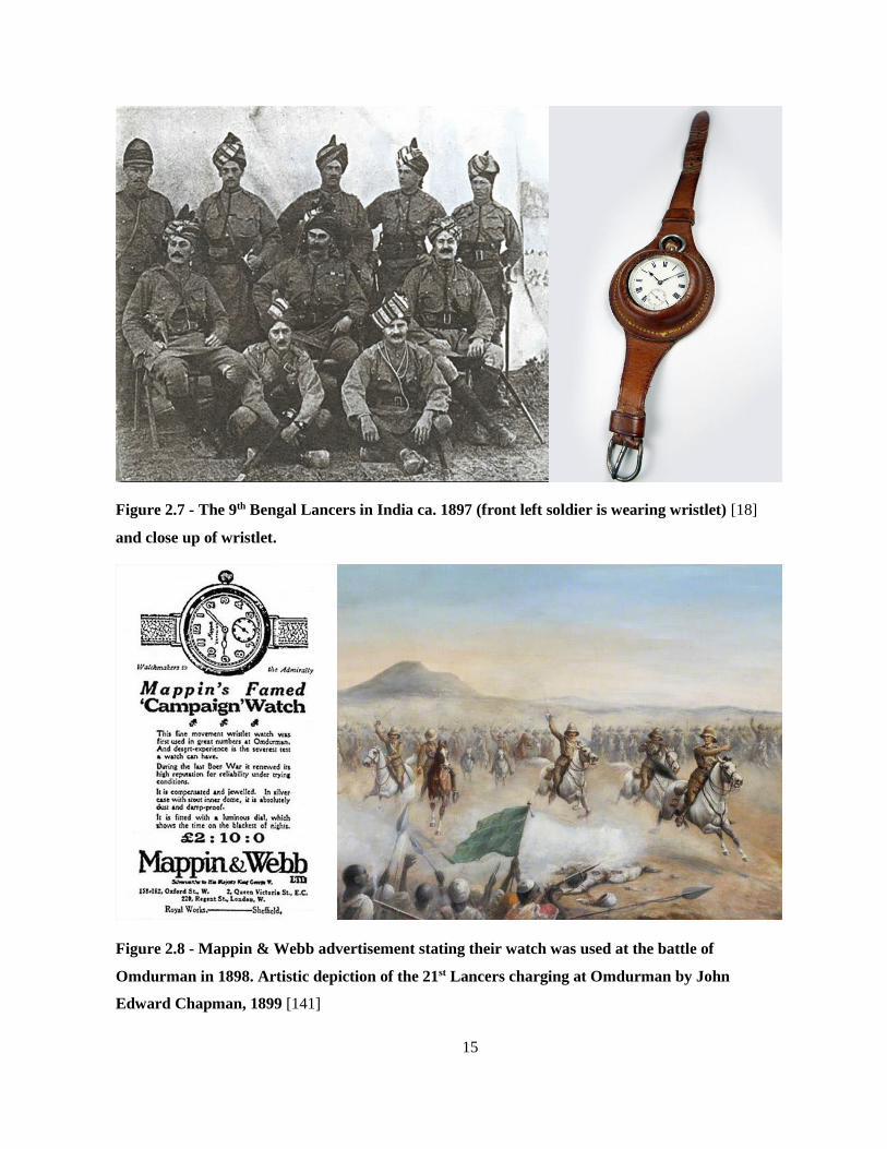
saddle makers to create leather wrist-bands to hold their pocket watches (Figure 2.7, right) [17].
The significance of the wristlet is that, unlike the bracelet watch, the watch face was always
exposed, thereby enabling the wearer to tell the time without requiring any engagement beyond a
quick glance.
These wristlets were eventually replaced by the wrist-watch. In 1880 the Swiss watchmaker Girard
Perregoux manufactured the first large batch of wrist-watches for the German Military. These
watches enabled German soldiers to handle weapons, heavy machinery and artillery while
monitoring the time [17, 142].
The British Military started using wristlets produced by Mappin & Webb at around the same time
(Figure 2.7, left & Figure 2.8). There are records of these watches being used in colonial conflicts
around 1880, in the Sudan Campaign of 1898 and during the Boer Wars of 1899 [17, 142] (Figure
2.8).
15
Figure 2.7 - The 9th Bengal Lancers in India ca. 1897 (front left soldier is wearing wristlet) [18]
and close up of wristlet.
Figure 2.8 - Mappin & Webb advertisement stating their watch was used at the battle of
Omdurman in 1898. Artistic depiction of the 21st Lancers charging at Omdurman by John
Edward Chapman, 1899 [141]

16
With the invention of phosphorous paints, it became possible to tell the time in the dark, further
expanding the use case of the wristwatch. The Radiolite wristwatch by Ingersoll, which used this
phosphorous paint, became an important tool in WWI. This marked a change in attitude towards
the wristwatch. Before WWI wristwatches were mainly used by people who today might be called
‘early adaptors’. During WWI Ingersoll produced up to 20.000 wristwatches a day. By the end of
WWI it is estimated that about fifty million wristwatches were in use and the technology was
widely used by people of all backgrounds [17].
History of the Wristwatch: Conclusion
From the first drum watches to the wristwatch there is an arc of technological development which
is indicative of how the adoption of smartwatches may proceed. We find that initially the new
technologies enabled by the mainspring and the fusee were used by a select few. The functionality
of the device was secondary, the main focus was either on the device as an ornament, a
demonstration of wealth and the appeal to be what we would today refer to as an ‘early adopter’.
Eventually two things occurred: The technology matured both in terms of the quality of the devices
as well as in terms of manufacturing processes. More relevant to us, as designers of technology, is
that its use case was recast. By removing the watch-face from the locket and placing it in direct
view of the wearer, users could tell the time by merely glancing at it. This allowed the technology
to recede into the background: supplying information, rather than requiring engagement. It is this
recasting of the wristwatch from an extravagant luxury item designed to draw attention, to a
contextual, glance-based interface, designed to recede from attention, which lead to its widespread
adoption.
2.3 The Digital Watch
There is a similar technological arc present in the development of digital watches. However,
working with new technologies also lead to series of new concepts that we will highlight in this
section. Still, the current generation of smartwatches suffers from some of the same issues as the
wearable technology of the 16th century did. They are popular and fashionable, however beyond
that their use case is not clearly defined yet.

17
Ornamental Devices
In 1972 the Hamilton Watch Company presented ‘Pulsar the Time Computer’, the first
commercially available digital watch. In 1975, the Hamilton Watch Company introduced the first
interactive digital watch, adding calculator functionality (Figure 2.9) [111].
Figure 2.9 - Pulsar Time Computer [30] 3
There are many similarities between the Pulsar (Figure 2.9) and the drum watches by Schissler
(Figure 2.2). They were clearly marketed as luxury items. Both the original Pulsar Time Computer,
as well as the Calculator Watch were originally released in a limited edition featuring 18 karat gold
and sold for $1500 and $3650 respectively [111]. Just like the mechanical watch had drawbacks
compared to the sun-dial, the digital watch was significantly less practical than watches with a
physical display: due to the high power demand of the LED display, it only would display the time
once a button was pushed and, of course, required batteries to operate. The calculator on the 1975
model was also not particularly useful as a tool compared to the portable calculators available, for
example, from Texas Instruments. The Pulsar was, however, prominently featured in Playboy [52]
and featured in the James Bond movie ‘Live and Let Die’ [77]. Like the early Drum Watches, these
devices were status symbols, worn to impress: showing off wealth, influence and technological
prowess.
3 Original images posted by user ‘Stealth-wagon’ on
http://www.pistonheads.com/gassing/topic.asp?t=754644

18
Similar to early mechanical watches, these digital watches were also great feats of both engineering
and craftsmanship. They were designed and built before infrastructure existed which would allow
them to be mass produced. To put this in context, these were the days of main-frame computers,
more than five years before Apple would demonstrate the first commercially successful ‘personal’
computer. Their internal organization demonstrates both the beauty and ingenuity of their designs
(Figure 2.10).
Figure 2.10 - 'Motherboards' of the Uranus (left) and a Pulsar Calculator Watch (right) [110]
New concepts introduced with the digital watch
Solar watches appeared almost at the same time as the battery-only models. Due to the additional
technological and structural constraints introduced by the added photo-voltaic elements, designers
had to rethink the layout of the watch, forcing them to explore alternative form factors. Early solar
watches reconfigured the display to point towards the side, rather than upward, leaving the upward
position free for the photo-voltaic power harvesting systems. Examples of such watches are the
Synchronar [133] (Figure 2.11, left) and the Nepro Alfatronic [96] (Figure 2.11, right).

19
Figure 2.11 - Synchronar [133] and Nepro Alfatronic [96]
One of Seiko’s contributions to the digital watch in the early 1980’s was linking it wirelessly to a
larger input module. This approach combines the advantages of a lightweight mobile device with
the benefits of having a larger base station for more complex input (Figure 2.12). Another
interesting wristwatch was introduced in 1990 by the German watchmaker Junghans [152]. The
consumer appeal of their Mega 1 was that it set the time automatically, using a radio signal it
received through an antenna integrated with the watchstrap. The alternative form factors of the
solar watches, linking watches with larger input devices and using the strap as a functional element
are all design choices that are actively explored in contemporary HCI research.
In the years to come, various companies contributed technological prowess and design ideas to the
digital watch. Notable are Texas Instruments, who were able to produce very cheap digital watches
due to their integrated circuits [138] and companies such as Casio who worked on expanding the
functionality of the digital watches with integrated sensors [25]. Providing a comprehensive
overview of all such developments is, however, beyond the scope of this thesis.

20
Figure 2.12 - Seiko Calculator Watch [121]
Expanding the functionality of the digital watch
A recurring design goal for smartwatches is to turn them into full-fledged general purpose
computers. In 1998 wearable technology pioneer Steve Mann [126] and shortly after him
researchers at IBM [95] designed and built wrist-watches running Linux distributions (Figure 2.13).
While IBM went on to collaborate with design firm Citizen on product designs [61, 95], Mann
himself was disappointed with the result. In his own words “conclusion: smartwatch not too useful”
[127]. He abandoned this line of research in favor of his interest in head-mounted devices.
Figure 2.13 – Linux watch by Mann [126], OLED and LCD versions of Linux watch by IBM [95]
The idea of more general purpose wearables was followed up upon by Microsoft. In 2004 they
presented their visionary Smart Personal Objects technology (SPOT) [90, 153] which used FM
signals for communication. The idea behind SPOT was to provide useful bits of information to any
device that might need them, including news updates and messages over MSN Messenger [153].

21
SPOT was never able to fully establish itself, as their proprietary radio service was outdated almost
immediately after inception due to the proliferation of cellular data and eventually WiFi. The
service was discontinued by Microsoft in 2008 [153].
Figure 2.14 – Samsung SPH-WP10 Phone Watch [115]
A similar approach to adding functionality to the wristwatch, though less visionary in scope, was
followed by Samsung, who, starting in 1999, introduced a series of phone watches with the SPH-
WP10 (Figure 2.14). They expected them to “be a big hit with the youth market” [115]. It was not
until their 2014 Galaxy Gear 2 that Samsung had significant success on the wearable market.
Current SmartWatches
In recent years, various companies have attempted to gain a foothold in the wearables market.
Notable among those are Pebble [101] along with other, more established companies such as Sony,
Qualcomm, Motorola, Samsung, Apple & Google (Figure 2.15).
Figure 2.15 - From left to right: Moto 360, LG G Watch, Samsung Gear Live [6], Apple Watch
[8], Pebble Time [64]

22
It is interesting to note that the current generation of smartwatches is mainly designed by companies
known for their smartphones, not for their watches. While the manufacturers have attempted to
expand the functionality of the smartwatch, it appears that they are emulating the look and feel of
traditional wristwatches. It should also be pointed out that there are only limited attempts in
expanding the input and output space of the smartwatches. Instead, many companies appear to be
miniaturizing both the physical design and interaction design of smartphones and adding straps to
make them wearable. This is most apparent with products such as the Samsung PhoneWatch, but
can also be observed when comparing the shape and design of the Apple Watch to the current
generation of the iPhone.
The Digital Watch: Conclusion
There are parallels between these smart-watches and early wristwatches. For example, the
marketing campaign surrounding the Apple Watch focused on its aesthetic, and the different
available styles [9]. Though initially announced in September 2014, it is not until March 2015 that
Apple presented videos demonstrating how to actually use their Watch [28]. It appears that the
functions of the Apple Watch are only complementary to its primary purpose as a fashion and
lifestyle accessory, making it reminiscent of both the Hamilton Pulsar (Figure 2.9) and Schissler’s
Drum Watch (Figure 2.2).
It should also be noted that even the most recent generation of smartwatches constrains itself to the
traditional shape of wristwatches, while adopting interaction methods traditionally used with
mobile phones. We believe these to be arbitrary design choices, based purely on tradition, and not
on functional considerations. In this thesis we intend to demonstrate an approach to redesigning the
smartwatch focusing on its function as a contextual information device. In doing so, we break with
tradition in terms of the devices form factor; however our functional considerations are deeply
rooted in the history of wrist-worn devices.
2.4 Enabling Technologies
Just as the fusee and the mainspring were crucial for the development of the wristwatch, we believe
that there are a series of core technologies which will drive the development of smartwatches. This
is not intended to be an exhaustive list, but rather features two technologies which were important
to us in conceptualizing and implementing DisplaySkin.

23
Flexible Displays
In the early 20th century, mobile technology transitioned from being carried in a pocket, to being
strapped to the wrist. In order to make that transition, the technology was required to be more
robust, because of the environmental forces it would be subject to when worn on the wrist. We are
currently witnessing a similar process of technology migrating from the pocket to the wrist. A
technology which will be relevant for this transition is that of flexible displays.
There are a number of reasons that make flexible displays a desirable technology for wrist worn
devices. While the rigid displays on most portable devices today are relatively durable, they are
designed with the assumption that they are carried in a pocket. Flexible displays represent a step
towards increased ruggedness, as they are less likely to break or crack, which makes them better
suitable for being worn on the wrist. Flexible displays are also lighter than traditional displays,
making them more comfortable to wear. Finally, flexible displays can bend to conform to the shape
of the user’s wrist and allow a device to open and close, changing shape so that removing the device
from the wrist becomes more convenient.
Figure 2.16 – LED display (left), bi-stable Gyricon beads (center) [159], and magnetically actuated
bus display (right).
Most displays consist of a combination of driving circuitry and display technology. The displays
we are accustomed to on digital devices such as phones or laptops are controlled by an active matrix
backplane. This active matrix is an array of transistors which have individual control over each
pixel and, if applicable, subpixel. The display technology itself consists of light emitting elements
(Figure 2.16 left), bi-stable materials (Figure 2.16 center) or actuators (Figure 2.16 right) which are
inert, except if they receive input from the active matrix backplane.

24
Figure 2.17 - PaperPhone [68], Snaplet [137] and DisplayStacks [40]
E Ink, a technological successor to Xerox’s Gyricon technology [33, 159] was one of the first viable
display solutions for flexible displays. Using backplane technology developed by the Arizona State
Universitie’s Flexible Display Center, one of the first flexible E Ink prototype was presented in
2008 [60]. These displays were later used in prototypes by the Human Media Lab, such as
PaperPhone [68] (Figure 2.17 Left), Snaplet [137] (Figure 2.17 center) and DisplayStacks [40]
(Figure 2.17 right).
While the Flexible Display Center eventually focused on thinness rather than flexibility, Plastic
Logic developed large flexible active matrix display arrays [2]. Again, E Ink technology was
chosen for the display. These displays were, for example, used in PaperTab [135] which was
presented at CES 2013. Plastic Logic also developed color E Ink displays, which they used to create
a mockup of what a color E Ink wrist worn device might look like (Figure 2.18) [105].
Figure 2.18 – Color smartwatch mockup by PlasticLogic [105]

25
As flexible backplane technology has matured, large display manufacturers such LG and research
companies such as Universal Display Corporation have started using them to create flexible organic
light emitting displays (FOLEDs) [108, 145], which have since been used in smartphones such as
the Galaxy Round [116] and the G Flex [73] introduced in 2013. Unlike electrophoretic displays,
FOLEDs are full color, have a high pixel density and a high refresh rate capable of playing video.
This provides FOLEDs with a number of advantages over electrophoretic displays.
Flexible displays offer the opportunity to design devices with novel form-factors, including objects
with non-flat surfaces and bezel-less displays. In practice, such devices with non-planer form
factors are still barely explored and the few explorations usually use projection [3, 15, 16, 149] or
other simulation techniques [4, 55, 125]. In this thesis we will be taking advantage of flexible
displays for exploring previously unrealized device form factors.
Thinfilm solid state batteries
The largest component of most mobile devices is its battery. A lightweight, soft and flexible display
alone is of little use, if the battery is rigid and heavy. Such a device needs battery technology which
is similarly well fit for its form factor. Current batteries are designed based on the assumption that
a devices is fully charged and then is used as it discharges. Current trends in wireless technologies
and energy harvesting systems suggest that the way in which we use our batteries will change.
Instead of batteries designed to last as long as possible on a single charge, there will be growing
demand for batteries with lower capacity, but improved charging behavior [114, 166], which will
allow them to better take use of power-harvesting methods and wireless charging. Finally, as
battery technology is deployed closer and closer to the body, safety becomes an increasing issue.
The Lithium Polymer batteries, which are the current go-to technology for mobile devices are a
candidate for catastrophic failure in the form of explosions and fires [76]. We believe that wearable
technology requires a higher standard of safety of their power-supplies.
An interesting candidate for the thin, flexible, device of the future are thinfilm batteries. While their
capacity is somewhat lower than that of Lithium Polymer batteries, their form factor creates
interesting new opportunities for device design. Important benefits of thinfilm batteries are that
they are flexible [103], can be designed in arbitrary two dimensional shapes and that individual
cells (Figure 2.19, left) can be stacked to create larger batteries (Figure 2.19 right) [114]. Thinfilm
batteries also have both better charging capabilities and higher cycle life than lithium polymer

26
batteries. As an added bonus they are essentially safe: even if short circuited, or otherwise damaged,
they do not create excessive heat buildup, nor do they contain any fluids which can leak [114].
Figure 2.19 - Thinfilm, solid state, cell (left) and battery concept (right) [114]
Our prototype device will not include any integrated batteries. However, the form factor and power
requirements would allow it to be realized using thinfilm technology. In fact, a similar combination
of display and battery technology is used in the CST-01 (Figure 2.20) [63]. This digital watch
combines a thinfilm segmented display and battery technology with wireless charging and
communication, demonstrating how these technologies interact harmoniously, enabling elegant
and simple devices.
Figure 2.20 – CST-01, wristwatch [63] with segmented E Ink display, powered by
thinfilm micro-energy cell

27
2.5 Contemporary Research
Input Methods
Touch interfaces are a popular input medium for mobile devices. There are various reasons for the
popularity of touch. These include its relatively strong performance compared to other input
devices such as miniature joysticks, the coupling of input and output medium that aids compact
hardware design, and that it is an intuitive method of interacting with digital media [12]. However,
the small form factor of these devices leads to the the ‘fat finger’ problem: the softness of the
fingertip makes the interactions imprecise and the relatively large size of the finger compared to
the display leads to occlusion [12].
There are various strategies to sidestep these limitations. For example, Potter et al. demonstrated
that an offset curser can improve targeting precision [107]. Vogel and Baudisch developed this idea
further by dynamically displaying the target area next to the finger, when occlusion makes the
selection ambiguous [151]. Benko et al. explore this idea further by including bimanual gestures
for occlusion free touch interactions [13]. A creative way of sidestepping this problem all together
is to place the touch interface behind the device [12], which has also been explored for both
bimanual interaction and various cursor mappings [50, 164]. Behind-device interactions avoid
occlusion because the user touches the back of the device rather than the display.
While these strategies are feasible for handheld devices, they are not practical for wrist-worn
devices. Due to the size of current wrist-worn devices, which is even smaller than most handheld
devices, using offset cursors is impractical, and behind device interactions are not possible. It is
clear that wrist-worn devices require their own interaction methods, designed specifically with their
affordances and constraints in mind. In the following section, we will be introducing some
approaches for improving interaction on the wrist.
Extending Interaction Area
While interaction design for handheld devices commonly focuses on improving touch interactions,
research into input for wrist-worn devices tends to gravitate towards finding additional input
modalities, external to the display of the device. For example, Perrault et al [104] extend the input
area of a smartwatch by making the watchstrap touch sensitive. Perrault uses the extended touch
area for menu and list navigation, as well as gesture-space for eye-free input. Funk et al [38] use
this method for text entry (Figure 2.21). These prototypes are somewhat reminiscent of the

28
Junghans Mega 1 [152], as they also consider the wrist-strap as an active element in the functional
design of the device.
Figure 2.21 - Touch Interface on Wristband by Funk et al [38]
Ashbrook et al. explore how the inside of a bezel can be used as a guide to make touch interactions
on a round display more precise [10]. Oakley et al. point out that very small devices are becoming
more commonplace, and are not limited to wearables. They describe a strategy that avoids
occlusion by moving the interaction to the edge of the device, augmenting the outside of its bezel
with a series of outwards facing capacitive sensors (Figure 2.22, right) [97].
Figure 2.22 – Principles of SideSight (left) [21], device with capacitive touch on the edge [97]
Moving the interaction even further away from the device, various projects explore using the area
around it as an input space. This includes SideSight [21] (Figure 2.22, left) which was initially
designed for mobile devices and was adopted for with-wrist worn devices by Knibbe et al [67].
Both systems use infrared sensors pointing outwards from the bezel to detect gestures in the
surrounding area. This allows people to use the table a smartphone is placed on, or the skin around
a smartwatch, as an interaction surface.

29
Using the skin as a touch surface is a recurring theme in HCI research. For example, Nakatsuma et
al. [94] detects finger position on the back of the hand using a combination of piezoelectric and
infrared sensors. Makino et al. [85] measure the force and linear position of a finger between two
infrared sensors placed on the arm. Ogata et al. [98] present SkinWatch, which uses both touch on
the skin and skin manipulation around the device as input (Figure 2.23) Ogata et al. use the same
sensing approach as Makino et al. for map navigation and picture editing.
Figure 2.23 - Skin manipulation around the device as input [98]
While Makino and Ogata focus on continuous input on the skin, Harrison et al. presented several
prototypes which investigate sensing discrete input on the skin. For example, increasing screen real
estate by moving buttons off the device and on to the skin (Figure 2.24) [70]. Harrison also
demonstrated the use of acoustic triangulation and frequency matching to infer where the skin is
being tapped [46]. This is implemented in Skinput which uses the surface of the arm and hands as
tappable interface to wearable devices.
Figure 2.24 - Skin Buttons [70]
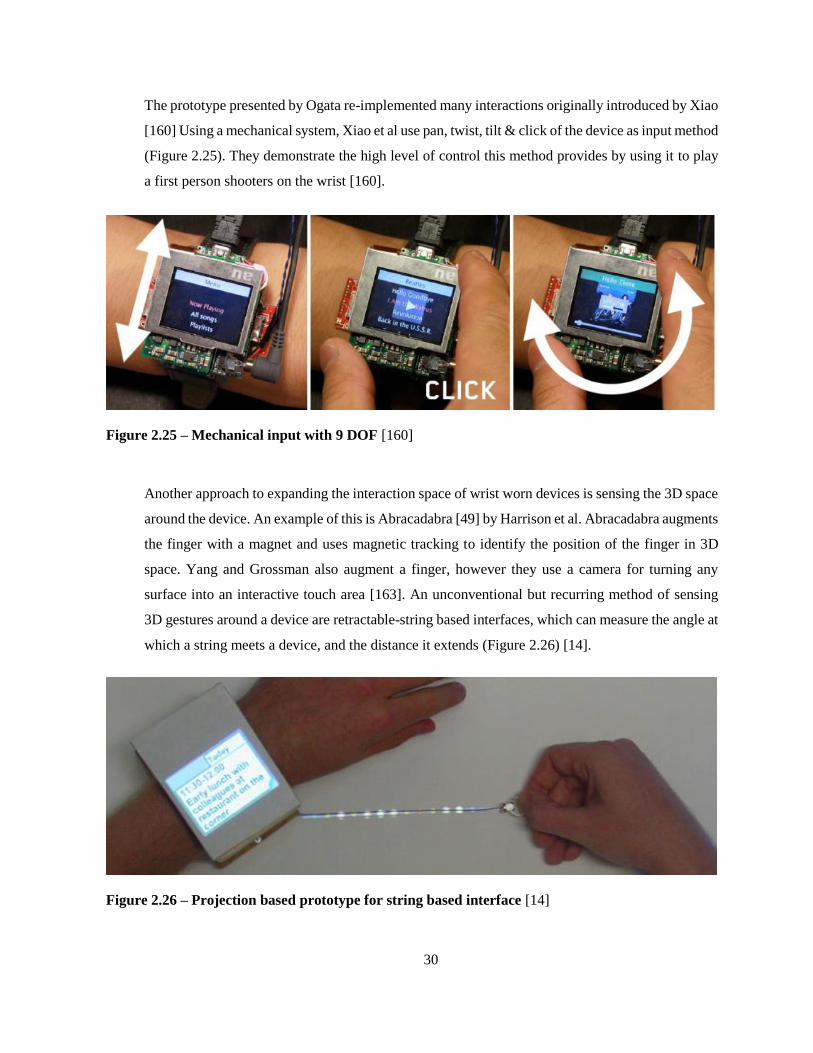
30
The prototype presented by Ogata re-implemented many interactions originally introduced by Xiao
[160] Using a mechanical system, Xiao et al use pan, twist, tilt & click of the device as input method
(Figure 2.25). They demonstrate the high level of control this method provides by using it to play
a first person shooters on the wrist [160].
Figure 2.25 – Mechanical input with 9 DOF [160]
Another approach to expanding the interaction space of wrist worn devices is sensing the 3D space
around the device. An example of this is Abracadabra [49] by Harrison et al. Abracadabra augments
the finger with a magnet and uses magnetic tracking to identify the position of the finger in 3D
space. Yang and Grossman also augment a finger, however they use a camera for turning any
surface into an interactive touch area [163]. An unconventional but recurring method of sensing
3D gestures around a device are retractable-string based interfaces, which can measure the angle at
which a string meets a device, and the distance it extends (Figure 2.26) [14].
Figure 2.26 – Projection based prototype for string based interface [14]

31
What these prototypes and explorations have in common is that they focus on offering alternatives
to using the display as a touch interface. As mentioned before, coupling of input and output, the
strong performance of touch interfaces and the compactness of the hardware make the touch display
a compelling input device. The motivation behind this research is that as displays become smaller,
they reach a point where touch interactions simply are no longer feasible. Once that point is
reached, these methods become appealing, as they overcome the limitations of the small displays
used with most wrist-worn devices.
Using Gestural Input
A drawback of the above methods is that they require both hands for interaction. The hand wearing
the device must be held steady for the other hand to reach and interact with the device. This requires
a significant amount of attention and effort for a device which was originally designed as a
lightweight contextual information display.
An approach that does not have this problem is decoupling the input from the device all together,
by enabling gestural input. For example, Rekimoto uses capacitance for determining the shape of
the wrist, by which he infers gestural information [112]. More recent explorations have used
Thalmic Lab’s MYO to a similar effect [62]. Other work which uses gestures decoupled from a
‘device’ includes work by Harrison. He uses a PrimeSense depth camera to track arm positions and
gestures [44, 45]. While not the focus of this thesis, we also have designed both resistive [130] and
infrared [129] implementations for one handed gestural interactions with wrist-worn devices,
which we will discuss at a later point.
These systems no longer explicitly require a ‘device’. Instead the body as a whole acts as an
interface to an interactive medium. Doing so opens up the design space to use proprioception (our
sense of the position and orientation of our body parts) as a feedback mechanism. For example, Li
et al. create virtual shelves which a user can reach for. The proprioceptive feedback users receive
when reaching for items helps the user remember where items are located [74]. Chen et al. suggest
similar interaction methods [22], for example, navigating data by moving mobile devices relative
to the body and creating a mnemonic map by storing and retrieving information at chosen locations
on and around the user’s body. Lopes et al. demonstrate a more abstract interaction language for
mobile devices which also relies on proprioceptive feedback, focusing on wrist interactions [78].

32
A drawback of these interaction methods is that they require us to be free to move our bodies at
will. They also overload our sense of proprioception in ways which might not be suitable,
depending on context. When riding a bicycle, for example, we are not free to use our bodies to
engage in this type of interaction. Our experience of our body is important when bicycling,
providing us with important feedback, enabling us to balance as we move through the streets.
Rather than overloading this feedback mechanism with additional layers of meaning, we suggest
that a device could make use of such information to infer the context within which it is being used.
A slightly different but related mechanism was, for example, explored by Tarun et al [137, 154].
Tarun allows the device to conform to the shape of the body, resulting in a different shape when
wrapped around the wrist as a smartwatch or held to one’s face for a phone call. Snaplet can sense
its shape configuration and adjust its functions accordingly. We suggest that wrist-worn devices
could take advantage of the user’s body configuration in a similar way.
Infrared Sensors
In our design process, we used infrared (IR) sensors for prototyping and also for the
implementation. This approach has a long history, and there is a significant amount of related work,
most prominently, frustrated total internal reflection introduced by Jeff Han [43]. Our sensors
however are more closely related to earlier work by Han on the bidirectional properties of LEDs
[72, 80]. Microsoft Research introduced prototype devices using this approach, including SideSight
for creating a touch interface around a device [21], and ThinSight, an augmented gesture sensing
LCD display [54]. Similar sensors to our approach are used for various other applications, from
touch-less interactions in public restrooms to optical pickups in musical instruments [122] and
sensing touch interactions with the skin [85, 98].
Output Methods
The small display of most smartwatches requires special attention on the output design as well.
Haptics have been a popular method: haptic impulses can serve as indicator or act as a low
bandwidth communication channel [81]. Haptic features can also provide guidance for eyes-free
input [10]. Other methods of haptic output which have been explored are temperature displays
based on Peltier elements [158].
Xu et al. [162] explored using low resolution visual information and demonstrate prototypes of
traditional watch faces augmented with discrete visual indicators. The rationale behind her work is
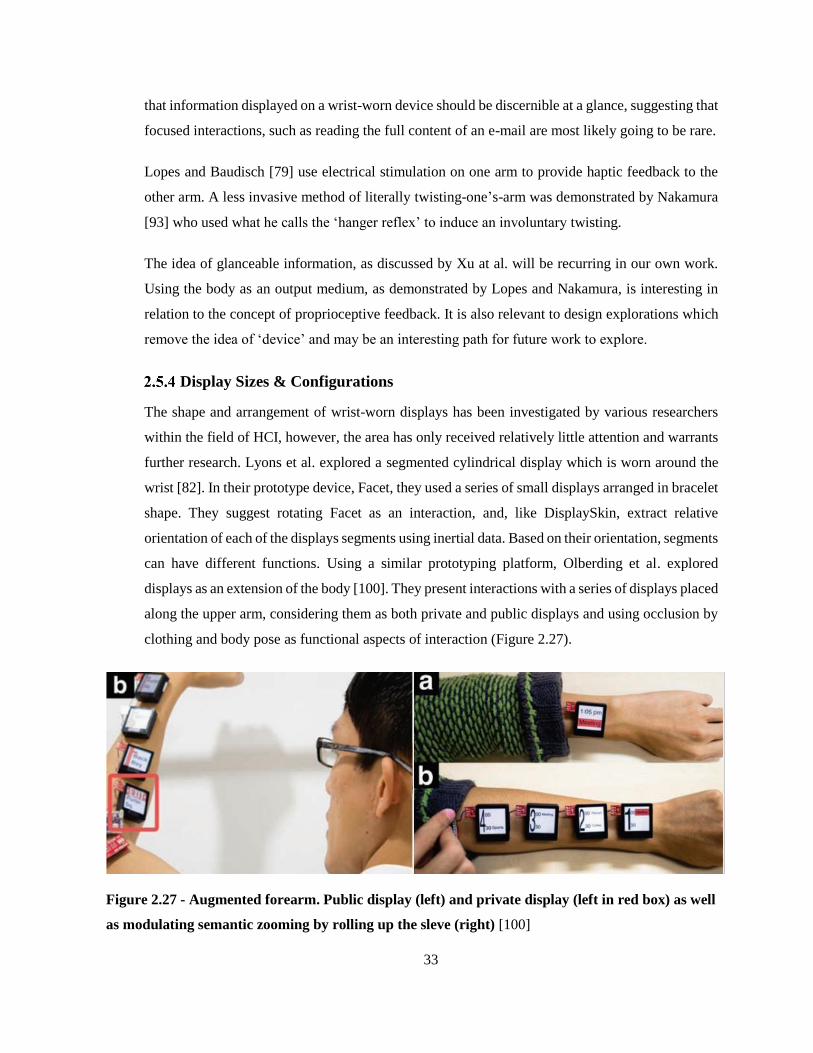
33
that information displayed on a wrist-worn device should be discernible at a glance, suggesting that
focused interactions, such as reading the full content of an e-mail are most likely going to be rare.
Lopes and Baudisch [79] use electrical stimulation on one arm to provide haptic feedback to the
other arm. A less invasive method of literally twisting-one’s-arm was demonstrated by Nakamura
[93] who used what he calls the ‘hanger reflex’ to induce an involuntary twisting.
The idea of glanceable information, as discussed by Xu at al. will be recurring in our own work.
Using the body as an output medium, as demonstrated by Lopes and Nakamura, is interesting in
relation to the concept of proprioceptive feedback. It is also relevant to design explorations which
remove the idea of ‘device’ and may be an interesting path for future work to explore.
Display Sizes & Configurations
The shape and arrangement of wrist-worn displays has been investigated by various researchers
within the field of HCI, however, the area has only received relatively little attention and warrants
further research. Lyons et al. explored a segmented cylindrical display which is worn around the
wrist [82]. In their prototype device, Facet, they used a series of small displays arranged in bracelet
shape. They suggest rotating Facet as an interaction, and, like DisplaySkin, extract relative
orientation of each of the displays segments using inertial data. Based on their orientation, segments
can have different functions. Using a similar prototyping platform, Olberding et al. explored
displays as an extension of the body [100]. They present interactions with a series of displays placed
along the upper arm, considering them as both private and public displays and using occlusion by
clothing and body pose as functional aspects of interaction (Figure 2.27).
Figure 2.27 - Augmented forearm. Public display (left) and private display (left in red box) as well
as modulating semantic zooming by rolling up the sleve (right) [100]

34
Integrating body and device
Chris Harrison explores scenarios that completely remove the idea of a device: Armura [45] and
OmniTouch [44] demonstrate interactions with projected displays on the skin, using hands and
arms as interaction surface (Figure 2.28) and enabling the user to transiently integrate objects with
their body, using them to expand their interaction vocabulary. Exploring a similar premise of the
body as an interactive medium, Katia Vega introduces the concept of beauty technology [147].
Vega uses makeup [66], fake eye-lashes [36] and hair extensions [146] as interfaces.
Figure 2.28 – The arm as interaction and display surface [45]
Placement of and Access to Mobile Technology
Ashbrook et al. conducted an experiment which required users to access information using a
smartphone or a smartwatch and found that participants are significantly faster in retrieving
information using the smartwatch [11]. There is a small body of work which further explores where
on the body a wearable device should be placed to minimize interruptions and be socially
acceptable. This research takes both the user and people interacting with the user into account.
Harrison et al. explored where on the body users are able to react fastest to a notification,
demonstrating that notifications on the wrist lead to fastest reaction times compared to various
other locations on the body [47]. Cheng et al. [24] and Strohmeier & Kamphof [132] explore
touching and touch interfaces on other peoples bodies, suggesting the wrists to be a viable public
interface. Harrison also demonstrates that in terms of other people interacting with wearable

35
technologies, the arms and hands are the preferred surface for others to touch and look at [48].
These results also suggest that wrist worn devices can serve functions beyond how we currently
engage with wearable technology. The wrist as a location for a display also has the benefit that we,
based on proprioception, always know its location. Finally, especially with high-skilled manual
tasks, such as surgery, a wrist worn display is as close to the focus of attention without causing
occlusion of the task at hand.
Head Mounted Displays
While some, such as wearable computing pioneer Steve Mann, may argue that head mounted
displays make wrist worn computers obsolete [127] there are many reasons why one might disagree
with this assumption. For one, the social acceptance of head-mounted displays is still very low
[88]. This is possibly because passers-by have limited to no understanding of how the user is
currently engaging with the head mounted display [83]. A near-eye device which sidesteps this
problem is Loupe by Lyons et al [83] (Figure 2.29). Because Loupe needs to be actively brought
to ones face for accessing information, onlookers have a clear understanding if the user is engaging
with the device or with their environment. This approach limits the opportunities for non-focal
interaction, as the user is required to actively seek information. We believe that many of the
opportunities provided by head-mounted displays can also exist for wrist worn devices. While the
wrist is not continuously in the user’s field of view, it usually resides at least at its periphery, and
is easy to move into ones field of view. Engaging with a wrist worn device is, to a certain extent, a
public activity enabling third parties a sense of access to the interaction. Wrist-worn devices are
also more familiar to onlookers, which may provide further benefits regarding social acceptance.
Figure 2.29 – Loupe [83]

36
2.6 Conclusion
Looking at the history of the wristwatch, we have pointed out that the mechanisms responsible for
early adoption of technology, be it the drum watch or early wearables are different from the
mechanisms that lead to a wide acceptance and proliferation of those technologies. Particularly
wearable devices were initially adopted as fashion items. Once the devices were no longer
identified as a fashion-only device, but had practical purposes, it was used not only used by so
called ‘early adopters’ but accepted and used by the population at large.
The digital watch emphasizes that it is not the technology which dictates how it is used, but rather
our requirements of it. This is apparent in the parallels between various stages of adoption of digital
and analog watches. Current smartwatches still do not have a clearly defined use-case or interaction
language. We believe that a clearly defined re-casting of the smartwatch as a contextual device,
focusing on the requirements which lead to the adoption of the wristwatch in the first place – a
glance-based, contextual information display – may help establish the smartwatch as a useful tool,
rather than a vanity product.
Looking at the current related work, there are two issues which are apparent. The first is that a large
portion of design research investigating wrist worn devices seems to focus on the small display
size. While we do acknowledge that there is a value to this research, we believe alternatives should
also be explored, as there is no intrinsic reason for the small display size current wrist-worn devices
have. Therefore, the first part of this thesis sets out to demonstrate that larger display sizes are
possible and to investigate the benefits of using a larger display.
A second theme are investigations that blur the border between the user and the device: research
that engages with the body as an element of the interactive medium. This is the design principle
that underlines the second part of this thesis. We take a step back to reflect on what the specific
benefits of a wrist-worn device are for the user. Based on recurring patterns observed in the history
of wrist-worn devices and based on the results of our first experiment, we developed a pose-aware
display that will be introduced and investigated in the second half of this thesis.

37
Chapter 3
Building DisplaySkin, Evaluating Viewport Sizes
Based on the literature, display size is considered a limiting factor for interactions on the wrist. We
believe that the display size is not just a technological constraint, but also a constraint we artificially
impose on our designs based on the traditional form factor of wrist worn devices. In this section,
we describe the manufacturing process of DisplaySkin, a wrist worn device with a 7.2” diagonal
display. The display is 3” by 6.5” making it substantially larger than, for example, the 1” by 1.2”
inch display of the Apple Watch [19]. For manufacturing DisplaySkin we developed a novel
combination of thermoforming and 3D printing as well as a custom touch sensor, which are both
contributions in this thesis.
After implementing DisplaySkin, we set out to test how different display sizes might influence
interactions on wristworn devices. We chose a list scrolling task for our evaluation, as it is
representative of browsing apps on the Apple Watch [28] and because it has been used in a previous
exploration by Perrault et al. [104]. We compared three display configurations by adjusting the
active viewport size.
3.1 Implementation
Here we outline the construction of the physical structure of DisplaySkin and the design of the
multi-touch sensor. We opted to build our own device rather than use existing hardware as this
enabled us the freedom to explore the form factors we were interested in. We were interested in
creating a physical device, rather than a projection based exploration. Dealing with the challenges
of overcoming the constraints provided by a physical medium offers the opportunity to explore the
affordances of that medium. This may lead to design choices and discoveries based on factors one
would not have dealt with using projection or other simulated approaches.
Our laboratory had previously explored flexible displays in mobile devices. Making the leap from
thin-film devices such as PaperPhone [68], MorePhone [41], FlexView[20] or PaperTab [134] to a
device wrapped around the wrist is relatively obvious. In fact Tarun et al. had already done so with
Snaplet [136]. Unlike Snaplet however, we opted for a display wrapped around the entire wrist.

38
Technologies Used in DisplaySkin
The core element of DisplaySkin is the Plastic Logic flexible Display (Figure 3.1). Plastic Logic
produces flexible TFT-Matrixes which can be used for flexible touch-sensing, flexible camera
arrays or as driving circuitry for FOLED or electrophoretic displays [2].
Figure 3.1 – Flexible Plastic Logic Display, used in PaperTab [134].
Plastic Logic provides display evaluation kits to demonstrate their flexible backplane technology
with electrophoretic displays. These kits consist of a Freescale Linux embedded computer, custom
driver hardware and a 10.7” display.
The display itself consist of multiple layers with unique functions fused together (Figure 3.2). The
bottom layers is a protective plastic sheet. Merged to that is the active matrix substrate which
controls the electrophoretic display. The electrophoretic display is sandwiched between the active
matrix substrate and a color filter, which in turn is protected by another plastic encapsulation sheet.
Figure 3.2 - Layers of Flexible display [2]

39
While these displays provide us with a strong prototyping platform, they have a series of
limitations. For example, the display is flexible, but its connectors are not. Therefore the physical
connection between the display and its data and power connectors is prone to damage. Another
limitation of these displays is the driver software. It is only capable of showing images, but not
video. However, in order to do some of the more advanced interactions we envisioned, we needed
to continuously redraw the display at a reasonable refresh rate. To overcome this limitation we used
FlexKit [56], written by Holman and Burstyn. Their custom driver enabled fast updates up to 12
fps, which is fast enough for simple video animations.
Assembling the Display
Several steps were necessary to transform a PlasticLogic display into DisplaySkin. One of our first
obstacles was that the display was too large. We had to reduce it in size, so it could wrap around
the wrist comfortably.
As mentioned, the display is updated through power and data connectors forming a bezel on the
top and left of the display. If one cuts the display, all pixels that have an intact horizontal and
vertical line connecting to this bezel remain intact. Within this constraint, the display can be cut to
arbitrary shapes. We cut the display to a size which allowed it to wrap around a wrist, wide enough
to display information in arbitrary orientations (Figure 3.3).
Figure 3.3 - Cutting the Flexible Display

40
Another problem we encountered is that the display deteriorates from being bent. Minor bends do
not stress the material to an extent where it is damaged, however, if bent for a longer duration, or
to a sharper curvature, the stress causes the bond between the individual layers to break. This is
because the layers are flexible, but not elastic. When the display is bent, the inner layers are
compressed. This creates stress on the bonds between the layers. The compressed side will ‘pop
out’, breaking the bond between the active matrix layer and the electrophoretic display. Cutting the
display further weakens the bonds, making it more likely to deteriorate.
To wrap the display around the wrist, we had to find a way of creating the required curvature
without damaging the display. We therefore adressed these issues of ‘popping’ and connectors
breaking by creating a 3D printed frame. Once printed, we slid the display inside this frame (Figure
3.4). The 3D printed structure protects the connectors by supplying them with additional re-
enforcement and reduces the likelihood of the display ‘popping’ by applying pressure to the display
from both sides, preventing the individual layers from separating.
Figure 3.4 - Inserting Flexible Display in 3D printed frame
Once placed inside the 3D printed mold, we thermoformed the entire structure to give it its final
curved shape (Figure 3.5). Bending the entire structure when heated allowed the top protective
layer to expand, while the bottom layer could minimally contract. By enabling the top layer to
expand and the bottom layer to contract, we reduce the internal tension of the display, making our
prototype sturdier. There was, however, a negative side effect, as the color filter was no longer
aligned after this procedure, preventing us from displaying color images.

41
Figure 3.5 - Heat-Shaping the Display
After heat shaping, the resting state of the display was cylindrical and it could comfortably be
wrapped around the wrist (Figure 3.6). Although the structure maintained its cylindrical resting
state, it was flexible enough for opening to wrap around the hand. Once on the arm, a magnetic
clasp secured it in place.
Figure 3.6 – DisplaySkin in its thermoformed resting state
While cutting electrophoretic displays had previously been investigated by Gomes et al [41, 42]
the process of heat-shaping the electrophoretic display is novel. To the best of our knowledge,
thermoforming a 3D printed structure is also a novel prototyping method. The heat-shaping process

42
developed for the physical form of DisplaySkin arose from necessity, however, we believe it is a
generalizable method which may also prove beneficial for prototypes which are not subject to our
specific constraints: 3D printing a cylinder in its final shape would take significantly longer than
3D printing it unrolled and consequently heat-shaping it. This process also has the benefit that the
final cylinder is elastic along its circumference. If directly printed, the internal structure of the
cylinder would make it difficult to bend for opening and closing. Doing so might even break or
otherwise damaging the print.
Designing the Touch Sensor
Traditional Sensing Approaches
There are numerous ways of detecting touch on a surface [21, 43, 54, 70, 72, 91], two of the most
popular methods are capacitive and resistive sensing [5, 37, 57, 99]. Resistive sensors generally
consist of a layer with variable resistance between two conductive layers. If the two conductive
layers are compressed, the resistance decreases, which can be used to measure the strength and
location of a touch [37, 57]. Capacitive sensors are, strictly speaking, proximity sensors. An
electrode on the touch surface is charged, and the time it takes for the charge to dissipate is
measured. This discharge time is increased if a finger is in close proximity of the electrode, as the
conductive finger, the non-conductive air and the conductive electrode together from a capacitor.
This leads to the electrode maintaining its charge longer than it otherwise would. The change in
discharge times can be measured to detect touches [5, 99].
Touch Sensing on DisplaySkin
The combination of a curved, bendable surface and electrophoretic display make sensing touch on
our prototype challenging. Commercially available flexible capacitive overlays work very poorly
with electrophoretic technology as the capacitive field of the display drowns out any capacitive
signal induced by human fingers. Resistive overlays do not work with flexible displays, as any
change in curvature is also a change in internal pressure, making them unusable.
Discrete resistive pressure sensors can be placed underneath the device, however the resulting
touch resolution typically is poor [129]. Discrete DIY capacitive sensors can also be placed
underneath the display as demonstrated by Gomes and Vertegaal for MorePhone [41]. The touch
resolution of MorePhone, however, was also very low. A further problem with placing a sensor

43
underneath the display is that DisplaySkin is wrapped around the arm. The arm introduces sources
of false positives for both the capacitive and resistive solutions.
Figure 3.7 - Visualization of data readings from projected touch screen [129]
IR Sensors
Near-infrared (IR) sensing solutions can be used as an alternative to resistive or capacitive sensors
[129]. Like capacitive or resistive touch solutions, near-infrared (IR) sensors (Figure 3.7) can be
manufactured in arbitrary configurations. IR sensors, however, do not have any of the previously
mentioned drawbacks of resistive or capacitive DIY solutions. IR sensors can be used for sensing
touch, pressure and, acting as proximity sensors, can also sense the approaching finger in mid-air.
This makes them a well suited sensor for expressive, dynamic interactions. IR sensors also do not
require access to the interaction surface; instead of acting as an overlay or substrate, they can be
projected on the interaction surface from the side. This enables touch interactions using the skin as
touch-surface, for example in the proximity of a wrist watch.
Principles of IR Touch-Sensing
IR touch sensors consist of two elements: an IR emitter and an IR phototransistor (Figure 3.8). If
an object comes within the proximity of the emitter, light is reflected back, allowing a measurable
voltage to propagate through the phototransistor. Such a system can also measure finger-pressure,
as the flesh of the finger changes its IR reflectivity with pressure [129].

44
Figure 3.8 – Basic Components of IR sensing circuit [129]
We use flexible circuits [131] to enable the sensors to conform to the curved surface of
DisplaySkin, while making them as thin and lightweight as possible. We treat the incoming sensor
readings as pixels in an image and use blob-tracking algorithms for determining touch and gesture
information. The accuracy of the sensors in x & y dimensions depends on the density of its IR-
emitter and photo-transistor arrays. The accuracy on the z axis (distance from sensor) depends on
the distance between emitter and photo-transistor, their viewing angles, and the strength of IR
illumination.
Projected 2D Touch Sensor for DisplaySkin
For detecting touch interactions on the curved surface of DisplaySkin, we created a linear array of
alternating IR emitters and photo-transistors (Figure 3.9). For our emitters, we chose the SFH
4045N by Osram. The specific emitter was chosen because of its wavelength (950nm), its relatively
small viewing angle (18°) and because it can be mounted at right angles. For the receiving elements
we chose the PT12-21C/TR8 by Everlight, as it closely matched our emitter’s wavelength (940nm),
has a wide viewing angle (120°) and can also be mounted to a circuit at right angles. We found that
this setup maximized the resolution of the sensor: the small viewing angle of the emitter reduced
the ambient saturation of IR light, while the wide angle of the receiver enabled us to use software
interpolation between multiple receivers to enhance precision. We further reduced the incoming
ambient IR by encapsulating emitters and phototransistors in opaque silicone (Figure 3.9, bottom
and right). Because the interaction area is projected, this sensor is suitable for touch sensing on
flexible electrophoretic devices, such as DisplaySkin [19]. Using this sensor, we were able to detect
the fingers position with an accuracy of +/-3mm on the x axis. The sensor was sampled ~ 60 times
per second, which made it significantly faster than our display speed (12fps). The sensor therefore
did not introduce any additional latency into our system.

45
Figure 3.9 –prototypes of linear IR multitouch sensor used with DisplaySkin [129]
Limitations & Concluding Thoughts on the IR Sensor
In laboratory settings and for experiments and evaluations our sensor performed reliably, as
ambient IR could be controlled. In outdoor situations, IR from sunlight saturates the
phototransistors, potentially reducing the usability of the sensor. This effect can be mitigated by
taking two consecutive readings: one with active IR illumination and one without. Using the
differences between these readings for image processing can enhance the usability of IR sensing in
situations with high ambient IR.
Like the thermoforming method presented, this sensing approach was developed for DisplaySkin,
but we believe it is also generalizable. It can turn any surface into a multi-touch area without
requiring an overlay or access to the surface from underneath. This makes it a prime candidate for
exploring touch interactions on the skin, which take advantage of the dual feedback of skin touching
skin. The approach we use is also easily customizable and can be appropriated for various special
purpose sensing applications.
3.2 Evaluating the Effects of Different Display Sizes
Once the physical prototype was completed and the multitouch sensor implemented, we conducted
our first experiment: evaluating what impact different display sizes have on task completion times
in a list searching task.

46
Experimental Motivation
Emerging technologies such as flexible displays, batteries, and circuits enable innovative form
factors for wrist-worn devices. Despite these advances, most currently available smart-watches
follow the design of conventional watches: a small display attached to the wrist by a flexible strap.
This design has largely gone unquestioned in the past hundred years [17].
The physical limitations of the traditional wrist-watch layout also limit the range of potential
interactions. For example, a small display has a reduced area for touch input and is especially
susceptible to occlusion [67, 150]. Also, when creating menu items on small displays they need to
take up a large area of the available screen real estate, as the finger is very imprecise in selecting
targets [58]. This is especially problematic as the small display area means that only very little
information can be displayed at one time, requiring more user input than larger displays would, for
example, when scrolling through a list of items or reading text.
There is a large body of research investigating these issues, but while input for small displays has
been studied in detail, less attention has been devoted to studying the actual effects of display size:
Might a larger display improve interaction, independently of problems related to input? If the
interaction space is kept constant, does a larger display support more efficient or new styles of
interactions?
Experiment
Task
Participants were presented with a scrollable list of 184 countries, sorted alphabetically. In each
trial, an external display prompted the participants with the name of a country and asked them to
find it within the list. In all conditions, participants used relative touch scrolling with inertia to
navigate the list. Once the target item was visible, they tapped it to complete the trial. Although the
viewport size varied between trials, participants were free to navigate using the entire touch surface
of the display. In other words, the available input area remained constant throughout all conditions.
Task Motivation
The scrolling task was chosen based on a previous experiment by Perrault et al. which also used
the entire wrist-strap as an input surface [104] and because it is an activity often required of users

47
in current smart watch designs, for example, when selecting an app from the application menu on
the Apple Watch.
Figure 3.10 - Small (left), medium (center) and large, cylindrical, display (right).
Conditions
We used two independent variables, display size and target distance. We simulated three display
sizes using different viewports on the electrophoretic screen (Figure 2). The small display was a
1.55” (Figure 3.10, left) rectangle on the top of the wrist, similar to most smartwatches and the
display used by Perrault et al. [104]. The medium display consisted of a 4” rectangle that started at
the top of the wrist and covered the visible area of the display, as viewed from above. The large,
cylindrical, display (Figure 3.10, right) condition spanned the entire surface of the prototype.
We used 4 target distances, a subset of those evaluated by Perrault et al. [104]: 5 items, 20 items,
80 items, and 160 items. Each item had a height of ~1 cm. In the small display condition, the 5th
item is not visible at the start of the trial. It is, however, immediately visible in the large and
cylindrical conditions.
Measures
Our dependent measure was navigation time, measured from the onset of the prompt to when the
participant tapped on the correct target.
Experiment Design
We used a 3x4 factorial within-subject design with repeated measures. Our factors were: display
size (small, medium, and large) and target distance (5, 20, 80, and 160 items). Each participant
performed 6 trials per combination of factors, for a total of 72 trials. Condition order was counter-
balanced between participants. The experiment lasted approximately 45 minutes, including
practice. Participants practiced with each display size until they achieved less than 10%
improvement between trials.
48
Questionnaires
We asked participants to rate each displays size on: how efficient it was for searching, if it enabled
a good overview of the data, and if it was useful for bimanual interactions. Each question was
structured using a 5-point Likert scale of agreement (1: Strongly Disagree-5: Strongly Agree).
Participants
The experiment was conducted with 12 participants (9 male, 3 female) between the ages of 17-29.
Most participants were right handed (9/12) and only 3 wore a wristwatch. All participants had some
familiarity with touch gestures, e.g., on a smartphone or tablet. They were paid $10 for their
participation. Left handed and right handed participants completed the same task.
Hypotheses
We hypothesized that larger display sizes would have faster navigation times (H1). As a control,
we also hypothesized that larger target distances would result in longer navigation times (H2).
Results
Experiment Results
We analyzed the collected measures by performing a repeated measures ANOVA using display
size (3) x target distance (4) on navigation time. Table 3.1 outlines the means and standard errors
for list navigation time.
We found a significant main effect of display size (F2,22=24.13, p < 0.001) on list navigation time.
Pairwise post-hoc tests, with Bonferroni corrected comparisons, revealed that the small display was
significantly slower than both the medium and large (cylindrical) display sizes (p < 0.001). As
expected, the analysis also showed that target distance was a significant factor (F3,33=303.11, p <
0.001). Pairwise post-hoc comparisons, Bonferroni corrected, confirm that navigation times
differed significantly between all target distances (p < 0.001).

49
Display Size
Small Medium Large
(Cylindrical)
Overall 17.65
(0.64)
13.19
(0.58)
12.37
(0.57)
Target
Distance
5 7.21
(1.27)
2.92
(0.95)
2.60
(0.76)
20 11.59
(2.14)
8.03
(2.12)
6.94
(1.09)
80 20.56
(2.14)
15.65
(1.76)
14.95
(1.82)
160 31.24
(3.37)
26.17
(2.90)
24.98
(3.08)
Table 3.1 – Targeting times in seconds and their standard deviations
Questionnaire Results
Table 3.2 displays the median scores of the questionnaire responses. We analyzed the data using a
Friedman’s one-way ANOVA by Ranks on the participants’ ratings, with Bonferroni corrected
Wilcoxon Signed Rank post-hoc tests (evaluated by dividing the standard alpha of 0.05 by the
number of comparisons, α = 0.0167). Results showed a significant effect of display size on
participants’ ratings of their ability to use bimanual interactions (Friedman’s χ2 (2)=15.62, p <
0.001). Post-hoc comparisons reveal that the large (cylindrical) display was rated higher than both
the medium display (Z = -2.714, p < 0.007) and the small display (Z = -2.716, p < 0.007), and the
medium display was rated higher than the small display (Z = -2.511, p < 0.012).
Results also showed a significant effect of display size on participants’ impression of how
efficiently they could complete the task (Friedman’s χ2 (2)=14.15, p < 0.001). Post-hoc
comparisons reveal that the large (cylindrical) display was rated higher than the small display (Z =
-2.738, p < 0.006) and the medium display was also rated higher than the small display (Z = -2.653,
p < 0.008).
We also found significant differences in how users experienced their overview of data for the
different display sizes (Friedman’s χ2 (2)=13.82, p < 0.001). Post-hoc comparisons revealed that

50
the large (cylindrical) display was rated higher than the small display (Z = -2.694, p < 0.007) and
the medium display was also rated higher than the small display (Z = -2.766, p < 0.006).
Small Medium Large
(Cylindrical)
The display enabled bimanual interaction 2 3 4
The display supported task efficiency 2 4 4
The display provided an overview of the data 2 4 4
Table 3.2– Questionnaire Results (Median response. All different values are also
significantly different. The large display trended towards a higher result than the
medium display for all questions. 1 = Strongly Disagree, 5 = Strongly Agree).
Discussion
The results of our experiment suggest that there is a benefit of increasing the display size for list
navigation tasks. Results confirm our hypothesis (H1) that display size has a significant effect on
navigation time: the medium and large display sizes allowed for faster task completion. These
results show that the current display sizes of smart watches limit the ability to efficiently navigate
through information, even if the interaction space is larger than the display. As expected, we
confirmed our control hypothesis (H2) that larger target distances would result in longer navigation
times.
Participants took advantage of the larger interaction area. For the small display condition most
participants used a non-active area below the viewport for scrolling. This allowed them to scroll
without causing any occlusion of the active area. This demonstrated that our results are not
confounded by the known input issues of small displays. It also suggests that for most currently
available devices which do not have the extended input area, the occlusion introduced by touching
the small display would lead to even slower task completion times than the ones we found for the
small display.

51
Like most scrolling experiments, we observed that the task is composed of a number of sub-tasks:
1) the participant estimates the target position relative to their current position in the list; 2) rapidly
scrolls towards the target, either under- or over-shooting; 3) brings the target into the viewport with
slower and more precise scrolls and 4) selects the target.
When the target is already visible within the display, participants are able to skip step 2), an
opportunity provided by the medium and large, cylindrical, display sizes in the smallest target
distance condition. For larger target distances, this particular benefit does not occur. The overall
results, however, suggest that these two sizes provide a significant advantage for steps 1) and 3),
by providing the participant a better view of surrounding targets. Specifically, we see that the
absolute performance differences between target distance conditions are fairly stable across display
size conditions—suggesting a constant advantage provided by increased display size. The
relatively constant delta between navigation times for each list length is easily visible in a bar-
graph (Table 3.3)
Table 3.3 - Task completion times for target distance and display types in seconds, star
indicates p < 0.05
We would like to point out that the absolute navigation speeds are different from those observed
by Perrault et al. [104]. This difference in task completion times was likely due to implementation
differences in the scrolling physics model, which in our case was constrained by the slower refresh
times of the electrophoretic display used in DisplaySkin. This lead to a slower scrolling behavior,
which effected absolute task completion times. Relative task completion times (the ratio between
times to scroll through different list lengths) are however in agreement with Perrault et al.
0
5
10
15
20
25
30
35
5 Items 20 Items 80 Items 160 Items
Seco
nd
s
Task Completion Times for Target Distance
Small Medium Large

52
Effects of a Cylindrical Display
Bimanual Interactions
During our experimental evaluation, we observed distinct strategies in how participants interacted
with different display sizes (Figure 3.11). Many participants chose to support their left hand on the
table, as our experiment required them to scroll through lists for an extended period of time, which
they reported to be tiring despite breaks. With the small display size, participants often rested their
entire palm on the table (Figure 3.11 - A). In the large display size condition, participants often
lifted their hands, supporting the weight with their fingers (Figure 3.11 - B), while orienting the
active display area towards their face. In the cylindrical display condition, participants usually lifted
their hand from the table (Figure 3.11 - C) to leverage bimanual interactions.
Figure 3.11 - Typical hand positions for different Display Sizes
We noticed two ways in which participants used bimanual interaction with the cylindrical display.
When participants were close to the target, but it was not immediately visible, they would rotate
their wrist to bring it into view. In addition, participants also used the rotation of their left hand to
correct for the actions of the right: To accommodate for the inertial scrolling, they commonly
rotated their wrist to respond to an overshoot or in anticipation of an upcoming target.
These behaviors are supported by the questionnaire results. When asked to rate appropriateness for
bimanual interactions, 75% of the participants stated that the large, cylindrical, display supported
bimanual interactions (rating it with a 4 or 5), compared to 41.7% for the medium display and only
16.7% for the small display condition.

53
Mobile Interactions
The reason participants lifted their wrist off the table during the medium display size condition was
to orient the display towards their face. Viewed from the right angle, the viewport spanned the
entire width of the wrist. When the active display area is oriented towards the face, the medium
and large display sizes were visually identical. This, however, is true only if a user’s body is in the
correct pose for interacting with the display. The use of bimanual interactions for completing the
search task points to another affordance of the cylindrical display: it can be viewed from various
angles.
While the difference between the task completion times for the medium and large, cylindrical,
display sizes was not significant, we believe this to be based on the static nature of our experimental
setup. In day-to-day life, our bodies, and especially our hands, are usually in motion. Outside of a
laboratory setting, we would expect this property of the cylindrical display to demonstrate
additional benefits over the medium display.
Our results demonstrate that there is a significant benefit of larger display sizes with respect to task
efficiency, at least for list navigation tasks. This suggests that, while increasing the interaction area
has its own advantages, there is value in creating wrist-worn devices with larger displays. At the
same time, a display that wraps around the entire wrist was not significantly faster than one that
covers the top of the wrist. Users can, however, view a cylindrical display from any angle; they are
not constrained to a specific pose. This freedom allowed the participants to explore different
positions of the arm and the wrist, in turn inspiring them to navigate with bimanual gestures—
demonstrating that while the cylindrical display was not more efficient than the large display in our
controlled experiment, the form factor may provide additional benefits for mobile interaction.
Towards Glance-Based Interactions
The task chosen for our evaluation may not have been best suited for exploring the benefits
provided by a cylindrical display. As discussed earlyer, wrist worn devices are, due to their constant
availability, in a similar design space as head mounted displays. An advantage of a wrist worn
device is its long cultural heritage and stronger social acceptance, while a drawback of most
smartwatches is that while they are constantly accessible, they do not provide a constantly available

54
display area the way head mounted displays do. This constantly available display however provides
designers with a powerful tool to facilitate peripheral interactions.
Looking at the history of the wristwatch, peripheral, glance-based interactions are what initially
made it popular in the first place. The wristwatch provided people with a simple way of accessing
supplementary information, while minimizing interruption to their primary activity [124]. This
design principle is at the core of much of the interaction research surrounding head mounted
displays. For example, Vidal et al. use eye tracking to measure the focus of attention of users
wearing head mounted displays. Vidal uses this information to design interfaces which are
contextually appropriate: available when needed, and receding to the periphery if the user’s
attention, is elsewhere [148]. In many ways this makes wearable displays the spiritual successor of
the wristwatch.
The affordances of DisplaySkin however enables an interesting hybrid medium somewhere
between the static watch face, and the dynamic, always available, head mounted display. Because
of its cylindrical display, DisplaySkin always has active pixels which are facing the user. We can
take advantage of this by continuously re-orienting content towards the viewer to create a small
window to the digital world which moves with the user, never far from the periphery of their vision.
Such a device would be a suitable platform to combine both the positive affordances of the
wristwatch and of head mounted displays.
While this thesis so far has focused on the history, form factor and display size of wrist worn
devices, in a next step, we will take a closer look at using a wrist worn device as a glance-based
interface, intended to supplement primary activities. We will initially outline our design principles
before discussing our example implementation of these design principles: the pose aware display.

55
Chapter 4
Pose Aware Display
4.1 Concept
In our related work, we introduced various stories of how the first wrist-watch might have been
invented: A mother suckling her child. An aviator pushing the boundaries of flight. Motorists using
dangerous and experimental vehicles. Soldiers engaged in meticulously planned assaults. Hunters
stalking their pray. All these scenarios have a common thread: the people adopting the technology
are not interested in the device itself. They are engaged in an activity which is important to them.
The wristwatch is a convenient tool which supports fully concentrating on a primary activity, while
having access to supplementary information. The reason the wristwatch is convenient, is that it
provides this supplementary information with minimal distraction [19].
Figure 4.1 – DisplaySkin with pose-aware contextual information
Once we had found this common thread, we realized that this design goal is just as relevant today
as it was then: mobile devices provide people with contextual information. This information may
benefit a primary activity, assuming the information is easily accessible. The use case of a wrist-

56
worn device has not changed: just as in the 19th century wrist-watches were used to provide
contextual information to the primary activity at hand, a smart watch will most likely be used in
the same manner. As alluded to in our introduction, we have observed that in the previous years,
smartphones have taken over as the primary device for accessing contextual information. However,
it appears that this use cases for smartphones will be migrating back to our wrists, as it is easier to
glance at one’s wrist for information than it is to pull one’s phone from one’s pocket [11].
Our evaluation of different display sizes in the previous chapter demonstrated that one of the
strengths of the cylindrical display used in DisplaySkin is its potential for mobile interactions and
the quasi-always available display provided by its cylindrical form-factor. When implementing
further interactions with DisplaySkin, we therefore decided to utilize these affordances, most
importantly that the cylindrical display minimizes occlusion for most body poses. This allows the
device to function as a contextual interface and also enable the user to access information in
contexts in which a traditional smartwatch would be occluded (Figure 4.1).
Design Rationale for Wrist-Worn Devices
Design for Non-Focal Attention
One of the advantages of a wrist-worn display is that it is usually located not far from the focus of
our interaction. Gruber, for example, describes how, when he grinds his coffee in the morning, the
effortless access he has to his wristwatch allows him to gage how long the beans have been
grinding, without removing focus from the coffee grinding machine [140].
Based on this affordance of conventional watches, a key design consideration which we had going
forward with DisplaySkin was that Smartwatches should be designed for non-focal attention.
Traditional user interfaces assume that they are being actively attended to by the user. A wrist-
watch on the other hand is not something we typically are in continuous engagement with. Instead
we glance at it briefly for contextual information. This is reflected in the simple graphical
representation of time we see in traditional wristwatches compared to the complex and detailed
menus of traditional GUIs. In figure 4.2 we provide an example of these two design paradigms side
by side.

57
Figure 4.2 - Watch compared to the cluttered GUI of most applications
We argue that it is not useful to copy methods which have proven useful for focal interaction,
conceptually shrinking a computer and placing it on the wrist. Instead, we suggest enhancing the
existing light-weight affordances of the traditional wristwatch.
Design for Contextual Information & Minimal Interruption
In her motivation behind the design of her shimmering smartwatches, Xu states that she finds the
scenario in which we read the full text of an e-mail on our watch is unlikely to occur [162]. Not
only do we agree that such a scenario is unlikely, we also believe it is undesirable. To accommodate
using a smartwatch as a non-focal device, the information accessible to the user must also be
designed accordingly.
We envision DisplaySkin to be used with contextual information. Currently it is common to use
mobile devices for accessing contextual information to support a primary activity: for example to
consult a map when searching for a location in a foreign city. For the user to access this contextual
information, the benefit of having this contextual information must outweigh the interruption
introduced by accessing the mobile device. The user wandering through a foreign city is more likely
to take advantage of map-data and GPS information if this does not require them to stop and pull a
phone from their pocket. If one wishes to encourage accessing contextual information, it is
important that information is both appropriate and available as quickly as possible, with minimal
disruption of primary tasks. As demonstrated by Harrison [48], the placement of smartwatches on
the wrist is ideal for supporting this type of activity as it is easily attended to. Going forward, we
wish to further support this type of lightweight interaction.
58
Enable Glance-Based Interactions
As stated by TechCrunch, the most basic affordance of a traditional wristwatch is that one can
access information by merely glancing at it [155]. With the rising complexity of smartwatches, this
very basic feature is often no longer provided [140]. We argue that this trend ignores the most
valuable feature of wrist-worn devices.
Watches are, traditionally, glance-based device, offering contextual information without requiring
continuous engagement. Smartwatches should continue this tradition by supporting fast
interactions which may consist of nothing more than a fleeting glance. These fleeting interaction
are only possible if the user does not need to activate the device or search for content. In many
scenarios the wrist is an ideal placement for such a device, however, depending on one’s activity
and the body pose associated with, the display might be out of view or occluded. The design of
smartwatches benefits from considering glanceability as a design factor. Glanceability can be
improved by means of clear graphic design, of hardware such as a cylindrical display which
minimizes occlusion and by using software which presents information such that it is as easily
visible as possible.
Consider Body Pose
Whether a wearable device can be glanced upon or not is largely determined by body pose. Body
pose is also indicative of the type of activity a user is engaged in and can be an important implicit
or explicit input tool. Just as Vidal [148] uses visual focus as a metric for assessing the user’s
requirements of a head-mounted display, we believe body pose to be an important indicator for
engagement with a wrist-worn device. We argue that having access to information about the users
body pose is important for designing lightweight interfaces for wrist-worn devices.
While we appreciate the design motivation behind gestural watch interfaces [65] and devices which
make active use of our proprioceptive sense [22, 78], we caution against overloading body motion
and its feedback: our proprioceptive feedback and body language already is laden with information,
it helps us understand and express our emotional states [113, 128] and is invaluable in completing
day to day activities. Instead of overloading these information channels, we suggest taking
advantage of them to infer activity and mood as well as optimizing information retrieval.

59
The Pose Aware Display
While DisplaySkin’s cylindrical display has active pixels on every side of the hand, which
minimizes occlusion, this affordance of the cylindrical display is only useful if we know which
active pixels are currently viewable by the user. We therefore need to measure the users pose and
calculate where we can currently display information, so that it is not occluded. Additionally, to
make glancing at information as effortless as possible, we can then rotate content so that it is
oriented correctly towards the user’s face. We propose measuring the configuration of the user’s
arm in relation to the rest of the body and dynamically moving information onto an area of the
display that is visible. Presenting information in non-occluded areas is what makes the pose-aware
display feasible in the first place, while orienting information towards the users further reduces
interruption times, because it improves the readability of any text displayed on the device [156].
There is some previous research addressing similar problems. Cheng et al. [23] suggest adjusting
a displays orientation based on the users face, however, like most current devices, Cheng at al. only
enables two fixed orientations of content (landscape/portrait). In contrast, Wilfinger et al. [157]
used accelerometer data to continuously rotate content on steering wheel displays. Both of these
systems rotate content around a single dimension. We are suggesting a display which has access to
and takes advantage of the relative rotation between users face and the wrist in all three spatial
dimensions.
We call such a device pose-aware: a device which re-orients its content towards the user, rather
than requiring the user to orient their body towards the device. A pose aware display requires two
elements: a cylindrical display and a kinematic model of the body. By wrapping a display around
the wrist, DisplaySkin already has a surface with pixels always visible, independent of the rotation
of the arm. In order to implement this we need a system that measures the use of the user’s arm in
relation to the rest of the body. Once DisplaySkin has access to this information, we can
dynamically move information onto this area of the display that is visible to the user.
Building the Pose-Aware Display
Measuring Body Pose
For prototyping a pose-aware display we needed a method to detect the user’s motions and body
configuration. We envision DisplaySkin to be used in mobile interactions. With mobile we mean

60
both ‘in motion’ as well as ‘at different locations’. Based on this, we came up with the following
design constraints for our sensing solution: It must be wearable and it cannot require an
instrumented environment. To design interactions using body pose or gestures as input, being able
to track the wrist alone already provides us with a rich interaction space to explore. We therefore
focused on tracking the motion of the wrist and arm.
In the following section we will present three methods we explored in designing a wearable system
for measuring body pose. While we finally opted for an established method – kinematic tracking –
we will first present two of our earlier explorations as their simplicity make them a useful and novel
prototyping approach.
Detecting Wrist motion using resistive stretch sensors
One approach to measuring body pose information which we found worth pursuing is creating
clothing which can sense its deformation. For example, Gioberto et al. used stitching patterns of
conductive thread as a sensor for estimating joint angles [39]. Our own initial exploration in this
direction was a system called WristFlicker [130], which detects both wrist flexion and rotation
through stretch sensors embedded in a sleeve (Figure 4.3).
Figure 4.3 - WristFlicker stretch sensors placement: a) pronation/supination; b) ulnar/radial
deviation; c) flexion/extension [130]
We used conductive polymer by Images Scientific Instruments [1] as stretch sensors to measure
the movements of the wrist. The polymer cable is approximately 2 mm in diameter and can be
stretched up to 175%. The sensor’s resistance changes according to the amount of stretch. Once
the sensor is relaxed, the signal does not return directly to its baseline, but rather decays in an
approximately inverse exponential manner. To minimize this effect, we used two counteracting
sensors to measure each set of movement – while one sensor is stretched, the other is relaxed.
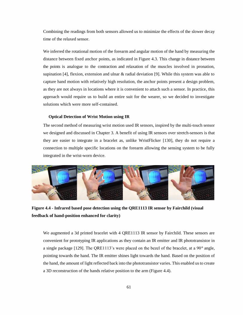
61
Combining the readings from both sensors allowed us to minimize the effects of the slower decay
time of the relaxed sensor.
We inferred the rotational motion of the forearm and angular motion of the hand by measuring the
distance between fixed anchor points, as indicated in Figure 4.3. This change in distance between
the points is analogue to the contraction and relaxation of the muscles involved in pronation,
supination [4], flexion, extension and ulnar & radial deviation [9]. While this system was able to
capture hand motion with relatively high resolution, the anchor points present a design problem,
as they are not always in locations where it is convenient to attach such a sensor. In practice, this
approach would require us to build an entire suit for the wearer, so we decided to investigate
solutions which were more self-contained.
Optical Detection of Wrist Motion using IR
The second method of measuring wrist motion used IR sensors, inspired by the multi-touch sensor
we designed and discussed in Chapter 3. A benefit of using IR sensors over stretch-sensors is that
they are easier to integrate in a bracelet as, unlike WristFlicker [130], they do not require a
connection to multiple specific locations on the forearm allowing the sensing system to be fully
integrated in the wrist-worn device.
Figure 4.4 - Infrared based pose detection using the QRE1113 IR sensor by Fairchild (visual
feedback of hand-position enhanced for clarity)
We augmented a 3d printed bracelet with 4 QRE1113 IR sensor by Fairchild. These sensors are
convenient for prototyping IR applications as they contain an IR emitter and IR phototransistor in
a single package [129]. The QRE1113’s were placed on the bezel of the bracelet, at a 90° angle,
pointing towards the hand. The IR emitter shines light towards the hand. Based on the position of
the hand, the amount of light reflected back into the phototransistor varies. This enabled us to create
a 3D reconstruction of the hands relative position to the arm (Figure 4.4).

62
While this sensor is promising as it can be integrated in the device itself, it is not possible to detect
rotation with this method. Also, while we found it to be useful for discrete gestural input, this
approach did not have the precision required for the type of analog input we were interested in.
Kinematic Modelling of the Arm
The resistive and optical methods showed potential for simple gestural input, however, they did
not provide the sensing resolution we wanted to achieve for DisplaySkin. We finally decided that
to construct a full kinematic model of the user’s arm. This would allow us to infer the position and
orientation of DisplaySkin relative to the user’s face.
To create this kinematic model, we used two Inertial Measurement Units (IMUs). One is worn
around the user’s upper arm and one is integrated in DisplaySkin. Each IMU contains a 3-axis
gyroscope, a 3-axis accelerometer, and a 3-axis magnetometer. Two Arduino boards collect the
data, and a sensor-fusion algorithm [84] calculates the absolute orientation of each IMU.
Figure 4.5 – Kinematic Model in foreground, Participant conducting experiment in background.
We use these headings to create a direct, forward kinematic model of a user’s arm. The model treats
the user’s shoulder as the base of an open kinematic chain with two links. Each IMU represents
one element in this chain and is considered a rigid body [117]. With this, we calculate the position
and orientation of the user’s wrist relative to their shoulder (Figure 4.5 shows the model in the

63
foreground with the users corresponding pose in the background). The model assumes that a user’s
face is in a fixed position relative to their shoulder, an assumption that is sufficiently accurate to
calculate the angle and rotation offset between the forearm and face.
Using this model, we can rotate information around the wrist so that it is pointing at the users face
(Figure 4.6, left) as well as rotate it relative to the face so that text or objects (or in case of Figure
4.6, right, the north position) remain upright. These two effects together enable an experience
described by a user as “a frameless window into another information environment rather than an
additional object to interact with“ [69].
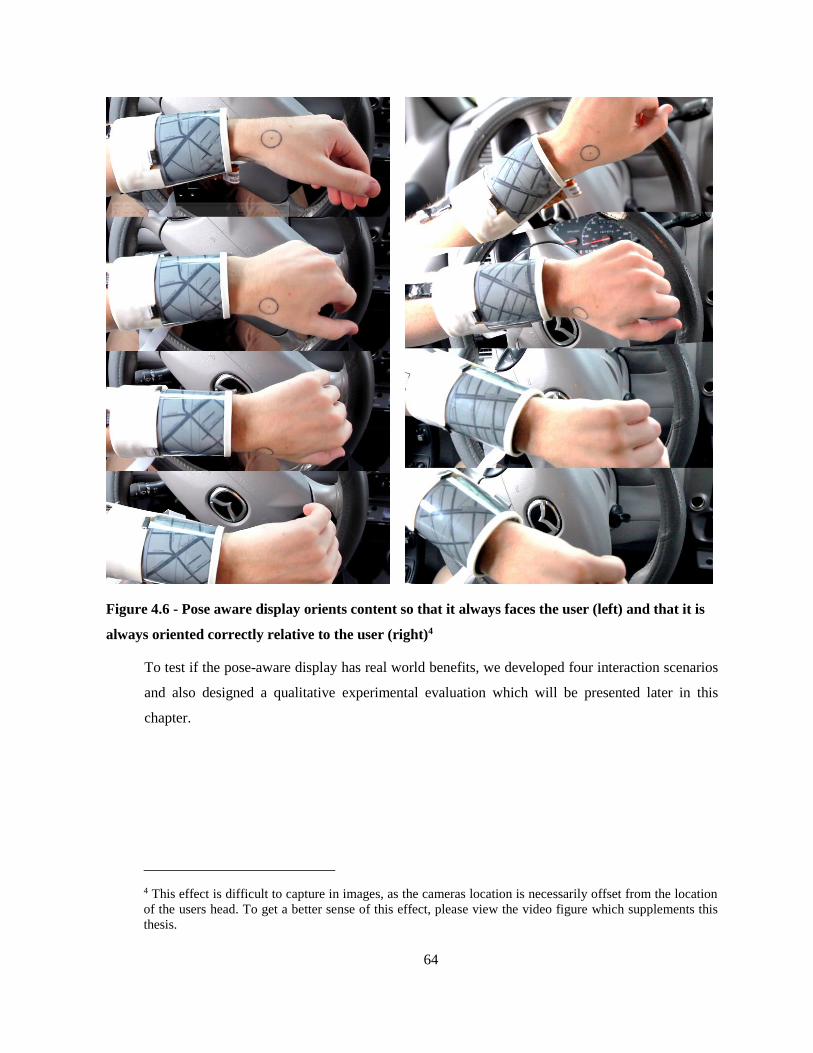
64
Figure 4.6 - Pose aware display orients content so that it always faces the user (left) and that it is
always oriented correctly relative to the user (right)4
To test if the pose-aware display has real world benefits, we developed four interaction scenarios
and also designed a qualitative experimental evaluation which will be presented later in this
chapter.
4 This effect is difficult to capture in images, as the cameras location is necessarily offset from the location
of the users head. To get a better sense of this effect, please view the video figure which supplements this
thesis.

65
4.2 Interaction Scenarios using DisplaySkin and a Pose-Aware Display
An advantage of having a display on the wrist is its close proximity to our focus of attention. A
dentist, for example, when working on a patient, balances their focus between the activity they are
engaged with and supplementary information such as X-Rays or perio charts. Moving this
supplementary information closer to their focus of attention reduces the interruptions introduced
by glancing at the information. Placing it on the wrist ensures that the information can never
occlude something that might otherwise be in view. The cognitive load of accessing the information
is further reduced by the pose-aware orientation of the information as well as by our proprioceptive
abilities, which enable us to know exactly where the display is located at all times.
Driving a Car
Using a current smartwatch while driving is an activity that could be described somewhere between
difficult and dangerous, as they usually require either gestures or bimanual interactions for
accessing content. Both our hands are, however, required to fully control the vehicle. If a driver is
required to conduct a maneuver which includes rotating their arm, a regular wrist-worn device with
might become inaccessible.
Figure 4.7 – Driving a car using DisplaySkin
We imagine that DisplaySkin might display information supplementary to the information already
present on the dashboard. DisplaySkin is better suited for this than traditional smart-watches as the
content will be visible independent of steering or other driving-related activities which influence
body pose. Additionally, information such as map-data would require the user to mentally rotate
the image if they were using a traditional wristwatch. As DisplaySkin knows its position relative
to the user, it could display a map which maintains its north orientation even when the arm is being
rotated (Figure 4.7). Because of our sense of proprioception, the fact that the display is not in a

66
fixed location relative to the rest of the information displays in the car, is not a problem: the user
always knows exactly where the display is, as it is linked to the hand.
Preparing Food
Figure 4.8 – Preparing Food using DisplaySkin
Cooking is a bimanual, visceral activity: kneading dough requires both of our hands and provides
us with rich feedback in form of textures ranging from smooth and silky flower to rough and sticky
dough. We also move throughout the kitchen, because different activities (straining pasta, placing
or removing items from the refrigerator, putting food in the oven, kneading dough) require us to be
in specific locations. If we wish to follow a recipe we are unfamiliar with, this can be a difficult
task as we are regularly changing location and our hands might be moist or dirty. Using
DisplaySkin provides users with an always available display that does not require us to modify our
behavior to use it, as the pose aware display accommodates the cooking activity we are engaged in
(Figure 4.8). A traditional wristwatch would be prone to occlusion based on our activity, while the
fact that our hands might be moist or dirty would impede interactions with traditional mobile
devices.
Using DisplaySkin to Augment Sports
The kinematic model used by DisplaySkin tracks the movements of the body. This can be used to
evaluate and reflect on athletic performances. DisplaySkin could record motion trajectories and
play them back for analysis. A user might, for example, compare their batting speed, as well as the
entire sequence of arm motions leading up to a hit, with those of famous players such as Derek
Jeter, or reconstructions of the performance of baseball legends such as Lou Gehrig or Babe Ruth.

67
Figure 4.9 – Playing Gold with DisplaySkin
In a sports context, DisplaySkin could take over three functions. It could provide the user with
information collected from external sources, it could measure motion sequences and it could
provide the users with statistics regarding their personal performance. DisplaySkin might, for
example, provide a golfer with contextual information relevant to striking the ball, such as wind
speed and direction. Once the user strikes the ball, DisplaySkin measures the angle and speed of
the swing. After the ball has been hit, the golfer can access information and statistics of their
performance on DisplaySkin (Figure 4.9). In team-sports such as soccer, where the referee is
constantly in motion, DisplaySkin could provide the referee with player information in a non-
disruptive way. In team games which require complex strategies to be decided upon in the spur of
the moment, such as American football, DisplaySkin replace the wristband traditionally worn by
quarterbacks.
Supporting Musicians
Different musical instruments require different body poses. A smartwatch could, theoretically,
provide a piano player with notation. Playing a guitar, on the other hand, requires a pose in which
the display of a smartwatch would not be visible. DisplaySkin on could recognize the pose and the
instrument and provide information accordingly. Once the user has selected a song, DisplaySkin
could support them by providing cues in the form of chords (Figure 4.10).
Figure 4.10 – Displaying Guitar Chords on DisplaySkin

68
We believe this to be an increasingly interesting scenario, especially with regards to new
instruments combining expressive motion and dance with music. Example of these might be ‘The
Hands’ played by Michel Waisvisz [32] and Imogen Heap’s Gloves [143]. DisplaySkin could
provide such artists not only with a display for musical notation or cues, but also with expressive
input abilities based on orientation of the arms and movement of the body.
4.3 Evaluating the Pose-Aware Display
The examples discussed in the previous section highlight interaction scenarios that would not be
possible with traditional wrist-worn devices. We were, however, also interested in assessing if the
pose aware display provides a benefit in more basic tasks, for example, acknowledging a
notification. We conducted an experiment to understand how pose-aware displays benefit
acknowledging a notification on the wrist. Instead of choosing a task that is completely impossible
with traditional smart-watches, such as the scenarios above, we chose a task which could be
completed with either type of device. We provided users with a primary task, and at certain intervals
required users to respond to a notification on a pose aware or static (fixed location on the top of the
wrist) display. We measured the participants’ ability to quickly acknowledge notifications
presented on DisplaySkin [19].
Experiment
Task
As a primary activity, participants performed a targeting task, similar to a one-dimensional Fitts’
law pointing test. Two bars appeared on a desktop monitor and spanned the height of the screen.
The bars were fixed in width and were varied in amplitude between conditions. Participants were
asked to move a cursor between the two targets as quickly and accurately as possible. They
controlled the cursor’s horizontal position with the rotation of their left hand. They selected targets
with a button they held in their left hand. This task allowed us to interrupt our participant’s activity
with the wrist in a controlled rotational position relative to the user’s body.
As a secondary task, participants performed an acknowledgment task on DisplaySkin. Upon
completing selected trials of the primary task, the participant was interrupted by a notification: the
monitor flashed red. Participants were instructed to, upon such notification, look at DisplaySkin,
find an arrow, and, using their right hand, swipe DisplaySkin in the direction indicated (Figure

69
4.11). Once the notification was acknowledged, participants returned to the rotational targeting
task.
Figure 4.11 – Participant being interrupted by notification. The arrow is pointed towards his face.
In the static condition the arrow would be mostly occluded.
By asking the participants to perform a task with wrist rotation, we were provided with a wide
variety of wrist angles. This, in consequence, allowed us to control the level of occlusion of the top
of the wrist at the moment when a notification occurred. For the pose-aware condition the arrow
was always in the participant’s field of view, while in the static condition, the arrow was partly
occluded, based on the current rotation of the wrist relative to the body. In addition, the demands
of the task required the participants’ full concentration, ensuring they could not plan for
interruptions.
Task Rationale
The motivation behind designing this task was less to prove beyond doubt the benefits of the pose-
aware display. Instead we wanted to better understand how users react to such a dynamic display.
The task is designed to provide basic information upon which more complex pose-aware
applications can be designed. Had we wanted to simply prove the benefits of a pose-aware display,
we would have introduced a task where a standard watch-face is fully occluded. Instead we
investigated the edge-cases, to better understand at which point a pose-aware device becomes
useful.

70
Conditions
We used two independent variables: display type and angle. The two display types were static and
pose-aware. The angles were 0°, 30°, 60°, and 90°. Figure 4.12 shows the position of the arm for
each condition, with a watch-face indicating the level of occlusion of the arrow for the static
condition. In the pose-aware condition, the arrow was dynamically placed in the participant’s field
of view.
Figure 4.12 – Angles used in our experiment
Controlling Wrist Angle and Hand Position
During a trial, the participant’s left elbow and right hand were in a fixed position. The participant
controlled the targeting task with their left hand and they held their right hand in a fixed position.
This allowed us to specify the rotation of the left forearm when the interruption occurred, as well
as ensuring that the distance between the right hand and the display was consistent between
participants, as it would influence the time required to complete the acknowledgement task.
Measurements
We recorded two dependent measures: homing time and resume time. Homing time is the time from
the moment of the interruption until the participant touched the surface of DisplaySkin. Resume
time is the time between completing the swipe to re-engaging with the targeting task, as indicated
by selecting the target that prompted the interruption. To do so the participants had to rotate their
left arm back to the orientation in which they were when interrupted and click the button they held
in their left hand.

71
Apparatus
Aside from DisplaySkin, we needed additional hardware to perform the experiment. To make sure
the resting position of the right hand remained constant, we instructed participants to place their
hand on a capacitive sensor, when not swiping DisplaySkin. To select targets in the primary task,
participants pressed a small push button that they grasped with the same hand with which they wore
DisplaySkin.
Experiment Design
We used a 2x4 factorial within-subject design with repeated measures. Our factors were: display
type (static and pose-aware), and wrist angle upon notification (0°, 30°, 60°, and 90°). Each
participant performed 8 trials of the acknowledgment task per combination of factors, for a total of
64 trials. Condition order was countered-balanced between participants. The experiment lasted 40
minutes, including practice. Participants practiced with each display type until they achieved less
than 10% improvement between trials. Participants clicked between the vertical bars for a total of
384 targeting trials. The trials were segmented into blocks of 6, grouped by target distance (each
target distance corresponding to a wrist angle). There was one interruption within each block of the
targeting trials. It occurred randomly when a participant clicked on the target bar that corresponded
to the desired wrist angle.
Participants
The experiment was conducted with the same 12 participants used in our first experiment. Most
were male (9/12) and they were between the ages of 17-29. Most participants were right handed
(9/12) and only a small number (3/12) wore a wristwatch. They were paid $10 for their
participation. Left handed and right handed participants were given the same task.
Hypotheses
We hypothesized that the pose-aware display would have faster homing times than the static display
(H1). We predicted that participants would be able to home to the wrist faster when the arrow was
dynamically placed in their field of view. We also hypothesized that larger wrist angles would
result in slower homing times for the static display, while times for the pose-aware display would
remain relatively similar (H2). We hypothesized that participants would have shorter resume times
in the pose-aware display condition (H3).

72
As a control, we expected that targeting times in the primary rotational pointing task would not
significantly differ between display types (H4), and that larger target amplitudes would result in
longer targeting times (H5).
Results
For the secondary acknowledgement task, we analyzed the collected measures by performing a
repeated measures ANOVA using display type (2) x wrist angle (4) on homing time and resume
time. Table 4.1 outlines the means and standard errors for homing and resume times.
Homing Time Resume Time
Static Pose-Aware Static Pose-Aware
Overall 1.84
(0.04)
1.5
(0.02)
1.75
(0.02)
1.69
(0.03)
0° 1.69
(0.04)
1.55
(0.03)
1.74
(0.04)
1.90
(0.05)
30° 1.82
(0.07)
1.52
(0.03)
1.60
(0.04)
1.85
(0.07)
60° 1.88
(0.10)
1.46
(0.04)
1.81
(0.05)
1.42
(0.05)
90° 1.90
(0.07)
1.47
(0.03)
1.88
(0.06)
1.59
(0.03)
Table 4.1 - Homing and resume times and their standard deviations in seconds
For homing time, the analysis showed that display type was a significant factor (F1,11=67.99, p <
0.001), with the pose-aware display resulting in shorter times than the static display. We also found
a significant interaction effect between display type and wrist angle (F3,33=3.29, p < 0.05).
With respect to resume time, we observed a main effect of wrist angle (F3,33=5.14, p < 0.05).
Pairwise post-hoc tests, with Bonferroni corrected comparisons, revealed that 0° was significantly
different from 90°. The analysis also showed an interaction effect between display type and wrist
angle (F3,33=15.12, p < 0.001).
For the rotational pointing task, we analyzed the movement times by performing a repeated
measures ANOVA using display type (2) x target amplitude (4). The analysis showed that target
amplitude was a significant factor (F3,33=219.48, p < 0.001). The analysis of the pointing task did
not show an effect of display type.

73
Discussion
Our results suggest that pose-aware displays reduce interruption times in interactions with a wrist
mounted display when attending to a primary pointing task. Resume times were faster larger angles,
and homing times were more efficient throughout. Swiping in the pose-aware condition was more
efficient, since the right hand travels a shorter distance to meet the left hand and there is no need
to explicitly rotate the left wrist to re-orient the arrow.
As hypothesized, our pose-aware display obtained significantly faster homing times than the static
display (H1). We believe this result is because the pose-aware display presented the arrow directly
in the participant’s field of view, regardless of their wrist angle when the notification occurred. In
addition, we confirmed our hypothesis (H2) that there would be an interaction between display type
and wrist angle. With the static display, larger angles resulted in larger homing times. The observed
effects are most easily understood looking at the difference in target times for each angle. Table
4.2 indicates how much the pose-aware display was faster for each wrist angle.
Table 4.2 – Advantage of pose-aware display for homing times in seconds
In our analysis of resume time we did not find a main effect of display type, rather we found an
interaction effect between display type and wrist angle. Again, the result is best understood when
we look at the differences in resume times. Table 4.3 shows that for small angles, the static display
actually was faster than for the larger angles.
0
0.1
0.2
0.3
0.4
0.5
0° 30° 60° 90°
Seco
nd
s
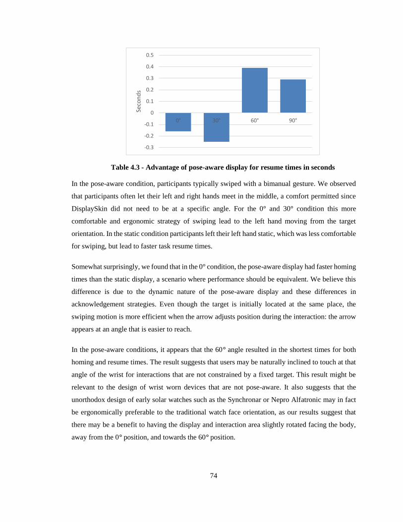
74
Table 4.3 - Advantage of pose-aware display for resume times in seconds
In the pose-aware condition, participants typically swiped with a bimanual gesture. We observed
that participants often let their left and right hands meet in the middle, a comfort permitted since
DisplaySkin did not need to be at a specific angle. For the 0° and 30° condition this more
comfortable and ergonomic strategy of swiping lead to the left hand moving from the target
orientation. In the static condition participants left their left hand static, which was less comfortable
for swiping, but lead to faster task resume times.
Somewhat surprisingly, we found that in the 0° condition, the pose-aware display had faster homing
times than the static display, a scenario where performance should be equivalent. We believe this
difference is due to the dynamic nature of the pose-aware display and these differences in
acknowledgement strategies. Even though the target is initially located at the same place, the
swiping motion is more efficient when the arrow adjusts position during the interaction: the arrow
appears at an angle that is easier to reach.
In the pose-aware conditions, it appears that the 60° angle resulted in the shortest times for both
homing and resume times. The result suggests that users may be naturally inclined to touch at that
angle of the wrist for interactions that are not constrained by a fixed target. This result might be
relevant to the design of wrist worn devices that are not pose-aware. It also suggests that the
unorthodox design of early solar watches such as the Synchronar or Nepro Alfatronic may in fact
be ergonomically preferable to the traditional watch face orientation, as our results suggest that
there may be a benefit to having the display and interaction area slightly rotated facing the body,
away from the 0° position, and towards the 60° position.
-0.3
-0.2
-0.1
0
0.1
0.2
0.3
0.4
0.5
0° 30° 60° 90°
Seco
nd
s

75
Although the targeting task was not the focus of this experiment, we conducted a statistical analysis
of the task to ensure that the conditions were consistent across both display types. We confirmed
our hypothesis that movement times did not differ between display types (H4) and larger
amplitudes resulted in longer times (H5). Even though non-significant difference is not
equivalence, these results are enough to suggest that the participants’ focus was on the primary
task.
A question commonly raised was if the moving images of the pose-aware display might not confuse
the user. This was not the case. In fact, the movements were so subtle and so well in sync with the
activity the user was performing, that most of our participants did not notice that the device was
pose-aware. In casual discussions after the experiment many of the participants were surprised
when we described how the pose-aware display worked. Subjectively, they simply experienced one
condition as more convenient that the other, without having any explanation, why this was. Even
more, they did not even consider it something to be curious about. Only once we explained the
mechanism to them, did they actively notice the effects of the pose-aware display. This
demonstrates that our prototype was true to our intent to design a glance-based interface for non-
focal interactions: in fact it did not draw the users’ attention at all.
4.4 Concluding thoughts to the Pose-Aware display
The most important difference between the various wearable watches popular from the 16th to the
20th century and the modern wristwatch is one of access. The bracelet watch, just as watch-pendants
and rings was designed as lockets. The user was required to open them to tell the time. These
devices required to user to interrupt their activity and engage with them for accessing information.
The wristlet on the other hand was designed with an open face. Users could tell the time simply by
glancing at it. This small change in design enabled the wristwatch to be used as a contextual tool
for non-focal, glance based, interactions. While the bracelet watch was jewelry designed to draw
attention, the wristlet was designed as a tool, intended to recede from attention. This change in
design philosophy lead to the popularity of the wristwatch as we know it today.
This affordance of the watch is lost in devices such as the Hamilton Pulsar. Requiring the user to
press a button to access the time, draws their attention away from their primary activity and instead
bringing the device into focus. The Apple Watch and many of the Android Wear smartwatches
have a similar design flaw. A user, for example, describes that they would usually use their
wristwatch to time how long they have been grinding their coffee. Because the display of their new
76
smartwatch needs to be explicitly turned on, and then set into a setting in which it does not time
out, this is no longer possible. In fact, the effort required to time the duration of grinding coffee has
become greater than that of grinding the coffee in the first place [140].
This example demonstrates the importance of designing wrist-worn devices as glance-based
interfaces, if they are to support the user in casual, day to day activities. Only few smartwatches,
for example the Pebble products, provide this opportunity. The pose-aware display is an attempt to
not only preserve this affordance of the wristwatch, but to improve upon it. We have received
criticism that our results, while significant, may not be relevant, as they only demonstrate minor
improvements in reaction times over a regular smartwatch. These minute improvements, however,
may result in the difference between requiring the user to actively attend to the device, or not. These
minute improvements allow the device to recede from attention, providing more opportunities to
present the user with information, while distracting less from the task at hand. This is further
supported by how unremarkable participants in our experiment felt the pose-aware display to be:
even as a novel technology, it did not draw any attention to itself.

77
Chapter 5
Limitations, Future Scenarios & Conclusion
5.1 Future Work
Ornamental use of DisplaySkin
This thesis has not explored any of the ornamental qualities of wearable technology, however,
looking at early technologies, such as the Drum Watch or Hamilton Watch Companies digital
wristwatch, one sees that their ornamental design was important. While the scope of this project
did not allow us to further pursue ornamental aspects of interactive wrist-worn devices, we find
that interaction space to be both fascinating and important. Interactive ornamental devices could
change their appearance on the fly, adjusting dynamically to suit the occasion. An interesting
concept device that explores this idea is the tago arc by liber8 (Figure 5.1) [75]. The tago arc is a
piece of wearable technology which explicitly serves an ornamental purpose. Its appearance can
be updated on the fly via a smartphones NFC system. It collects parasitic power for updating its
display via the NFC system as well.
Figure 5.1 - tago arc by Liber8 [75]

78
A pose aware device would enable dynamic interactive ornaments. Patterns could adopt based on
the pace at which the user is moving, for example, synchronizing to dance movements. Patterns
could also adjust dynamically based on the activity, for example, displaying subtle images during
activities where the wearer does not wish to draw attention to their hands, while otherwise allowing
them to present extravagant animated patterns.
Separation of Public and Private viewing areas
Ornaments have both a public and a private function. DisplaySkin could present directional
ornaments. For example, a picture of a loved one could be presented so as to face the viewer, while
a less intimate image, intended for public viewing could be pointed outwards. Such a mechanism
could be used together with functional content. Notifications, contextual information or interactive
elements could be presented towards the user, while viewed from an external space, DisplaySkin
would appear as an ornamental device. A similar mechanic has been suggested by Olberding et al.
[100], however, using DisplaySkin, private and public areas could be dynamically defined based
on current body pose.
Removing the device
DisplaySkin was in part inspired by design probes such as Kinisi by Katia Vega [66] (Figure 5.2,
center) and interactive tattoos by Phillips Design [120] (Figure 5.2, left). These design probes
remove the concept of device, instead considering the whole body as an interactive canvas.
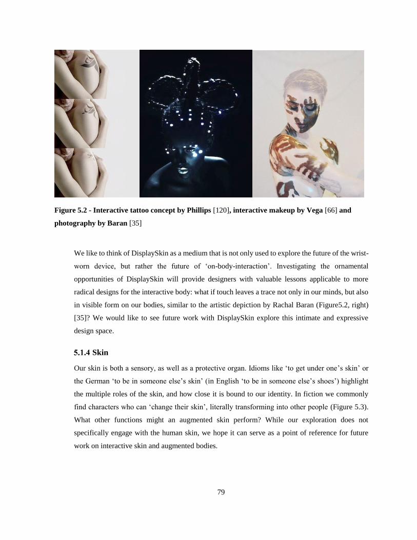
79
Figure 5.2 - Interactive tattoo concept by Phillips [120], interactive makeup by Vega [66] and
photography by Baran [35]
We like to think of DisplaySkin as a medium that is not only used to explore the future of the wrist-
worn device, but rather the future of ‘on-body-interaction’. Investigating the ornamental
opportunities of DisplaySkin will provide designers with valuable lessons applicable to more
radical designs for the interactive body: what if touch leaves a trace not only in our minds, but also
in visible form on our bodies, similar to the artistic depiction by Rachal Baran (Figure5.2, right)
[35]? We would like to see future work with DisplaySkin explore this intimate and expressive
design space.
Skin
Our skin is both a sensory, as well as a protective organ. Idioms like ‘to get under one’s skin’ or
the German ‘to be in someone else’s skin’ (in English ‘to be in someone else’s shoes’) highlight
the multiple roles of the skin, and how close it is bound to our identity. In fiction we commonly
find characters who can ‘change their skin’, literally transforming into other people (Figure 5.3).
What other functions might an augmented skin perform? While our exploration does not
specifically engage with the human skin, we hope it can serve as a point of reference for future
work on interactive skin and augmented bodies.

80
Figure 5.3 – X Men’s Mystique transforming from an adopted skin into her own [161]
5.2 Current Limitations
Our prototype was tethered to a dedicated driver board. When given the opportunity to explore
DisplaySkin before the experiment, some users noted the cables restricted their movement. Later,
they commented that for the more limited motion required in our experiments, the cables did not
interfere with their activities.
In our current prototype, our forward kinematic model requires users to wear, in addition to
DisplaySkin, a small (8 x 36 x 2mm) secondary IMU on their upper arm. Future research in tracking
algorithms may allow us to create an inverse kinematic model to remove this IMU. Trends in
wearable technology and tracking technology seen in systems such as NOTCH [59] suggest
however that the second IMU may actually be a feasible solution in the long term as well.
The chosen display technology suffers from a slow refresh rate. This was mainly noticeable when
implementing the physics model for scrolling. The slow refresh rates made very fast motion
difficult to visualize and was a constraining factor on scrolling speed, leading to longer scroll times
than expected. A display technology with higher refresh rate would mitigate this issue and would
also make the pose-aware aspects of the display appear smoother.
5.3 Conclusion
In this thesis we presented a variety of contributions to the design of wrist-based devices. We
initially presented a historic analysis of the development of the wrist-watch: we start with the first
portable mechanical devices of the 15th century, showing how technologies such as the mainspring
and fusee acted as catalyst for a generation of devices. These devices started out as vanity products
commissioned by the rich and powerful. The introduction of the wristlet moved the design space
of wearables away from a focus on fashion, towards a greater focus on utility. The main innovation
of the wristlet over previous wearable technology is its open face design. This enabled glance-
based interactions and lead to the transformation of the wristwatch into a non-focal interface. With

81
this transition of wearables from pure fashion accessories to contextual interfaces came a broad
adoption of wristwatches by the general public.
Many of the observations made on the development of the wristwatch can also be observed in the
evolution of the digital watch. Introduced as a limited edition extravaganza, the digital watch
eventually became useful as a tool. The new generation of smartwatches, however, introduces
design constraints similar to those found in the original Hamilton Pulsar or the first Drum Watches:
they require focal attention. By doing so, they neglect one of the key affordances that lead to the
wristwatches popularity.
While this key affordance appears to be lost in newer designs, the form factor of most smartwatches
constrain themselves to the traditional shape and size of the wristwatch. However, the interactive
elements of smartwatches are clearly inspired from tablet and phone interfaces. We believe these
to be arbitrary design choices. Instead, we suggest looking back at the factors that made the
wristwatch successful in the first place. Rather than implementing computers which can be worn
on the wrist, we suggest focusing the design of wrist-worn devices on non-focal, glance-based
interactions.
Based on these considerations we presented DisplaySkin: a pose-aware device with a large
cylindrical touch display worn on the forearm. DisplaySkin implements a kinematic tracking
system that enables it to be pose-aware. Its pose-aware display orients content towards the user’s
face, enabling fast glance-based interactions.
In implementing DisplaySkin we explored a number of novel sensing methods: infrared touch
sensors, infrared motion capturing sensors and elastic stretch sensors. These are documented to
facilitate the prototyping and design process of other designers. In addition to the sensing
mechanisms we demonstrate a novel method of creating 3D structures, by 3D printing a flat object
which is then thermoformed to achieve its final 3D structure.
Further contributions of this thesis are the two experimental evaluations of the prototype device.
We initially focused on the physical display of DisplaySkin, investigating the effects of display
size on wrist-interaction. The experiment demonstrates that larger displays enable faster list-
scrolling than smaller ones. At a certain size however, the visible are does not increase, as part of
the display is occluded. Once this occurs the additional display size does not make list searching
more efficient, however it enables participants to be more flexible in their body poses, enabling

82
bimanual interactions. This suggests that, in the wild, a cylindrical display would have additional
benefits, as it allows the device to be used in a larger range of poses.
This affordance of the cylindrical shape lead us to develop the pose-aware display. To evaluate
whether a pose-aware display helps users access information more efficiently, we designed an
experiment in which users performed a rotational pointing task that was interrupted by a task on
DisplaySkin. Results suggest that pose-aware displays reduce the time taken to acknowledge
notifications: if a user wishes to access contextual information, the pose-aware display minimizes
the interruption of a primary task. Our results also suggest that some areas on the wrist might be
more natural to touch than others and that pose-aware displays may be a useful method of further
exploring ergonomics of body-worn devices.
In summary, this thesis provides the following contributions to design research for wrist-worn
devices: (i) a historic analysis of related technology, (ii) design suggestions derived from this
analysis, (iii) three novel sensor designs, (iv) a novel rapid prototyping method, (v) a prototype
device, and (vi) two experimental evaluations of the prototype device.

83
References
[1] About Images SI, Inc: http://www.imagesco.com/about.html. Accessed: 2015-03-17.
[2] About Us | Plastic Logic: http://www.plasticlogic.com/about-us/. Accessed: 2015-03-15.
[3] Akaoka, E. et al. 2010. DisplayObjects. Proceedings of the fourth international
conference on Tangible, embedded, and embodied interaction - TEI ’10 (New York, New
York, USA, Jan. 2010), 49.
[4] Van Allen, P. et al. 2013. AniThings. CHI ’13 Extended Abstracts on Human Factors in
Computing Systems on - CHI EA '13 (New York, New York, USA, Apr. 2013), 2247.
[5] An introduction to Capacitive Sensing-Part I: 2012.
http://www.eetimes.com/document.asp?doc_id=1279563. Accessed: 2015-04-29.
[6] Android Wear - Google Store: https://store.google.com/category/android_wear.
Accessed: 2015-03-16.
[7] Apple - Live - March 2015 Special Event: http://www.apple.com/live/2015-mar-event/.
Accessed: 2015-04-27.
[8] Apple Watch - Pre-Order April 10 - Apple Store (Canada): http://store.apple.com/ca/buy-
watch/apple-watch. Accessed: 2015-03-16.
[9] Apple Watch gets 12 (mostly white) pages in Vogue: 2015.
http://fortune.com/2015/02/26/the-apple-watch-gets-12-mostly-white-pages-in-vogue/.
Accessed: 2015-04-20.
[10] Ashbrook, D. et al. 2008. An investigation into round touchscreen wristwatch interaction.
Proceedings of the 10th international conference on Human computer interaction with
mobile devices and services - MobileHCI ’08 (New York, New York, USA, Sep. 2008),
311.
[11] Ashbrook, D.L. et al. 2008. Quickdraw. Proceeding of the twenty-sixth annual CHI
conference on Human factors in computing systems - CHI ’08 (New York, New York,
USA, Apr. 2008), 219.
[12] Baudisch, P. and Holz, C. 2010. My new PC is a mobile phone. XRDS: Crossroads, The
ACM Magazine for Students. 16, 4 (Jun. 2010), 36.
[13] Benko, H. et al. 2006. Precise selection techniques for multi-touch screens. Proceedings of
the SIGCHI conference on Human Factors in computing systems - CHI ’06 (New York,
New York, USA, Apr. 2006), 1263.
[14] Blasko, G. et al. 2006. Prototyping retractable string-based interaction techniques for dual-
display mobile devices. Proceedings of the SIGCHI conference on Human Factors in
computing systems - CHI ’06 (New York, New York, USA, Apr. 2006), 369.

84
[15] Bolton, J. et al. 2012. A comparison of competitive and cooperative task performance
using spherical and flat displays. Proceedings of the ACM 2012 conference on Computer
Supported Cooperative Work - CSCW ’12 (New York, New York, USA, Feb. 2012), 529.
[16] Bolton, J. et al. 2011. SnowGlobe. Proceedings of the 2011 annual conference extended
abstracts on Human factors in computing systems - CHI EA ’11 (New York, New York,
USA, May 2011), 1159.
[17] Brearley, H.C. 1919. Time Telling through the Ages. Doubleday, Page & Co.
[18] British Empire: Armed Forces: Units: Indian Cavalry: 9th Bengal Lancers:
http://www.britishempire.co.uk/forces/armyuniforms/indiancavalry/9thbl1897b.htm.
Accessed: 2015-04-21.
[19] Burstyn, J. et al. 2015. DisplaySkin: Exploring Pose-Aware Displays on a Flexible
Electrophoretic Wristband. Proc TEI (2015), 165 – 172.
[20] Burstyn, J. et al. 2013. FlexView. Proceedings of the 7th International Conference on
Tangible, Embedded and Embodied Interaction - TEI ’13 (New York, New York, USA,
Feb. 2013), 193.
[21] Butler, A. et al. 2008. SideSight: multi-touch interaction around small devices. Proc. UIST
(2008), 201–204.
[22] Chen, X.A. et al. 2012. Extending a mobile device’s interaction space through body-
centric interaction. Proc. MobileHCI (New York, New York, USA, 2012), 151–160.
[23] Cheng, L. et al. 2012. iRotate: automatic screen rotation based on face orientation. Proc.
CHI. (2012).
[24] Cheng, S. 2011. Don’t touch: social appropriateness of touch sensor placement on
interactive lumalive e-textime shirts. Thesis, Queens 2011. August (2011).
[25] Chronology of Main Products - History - Corporate - CASIO:
http://world.casio.com/corporate/history/chronology/. Accessed: 2015-04-27.
[26] Clagett, M. 1995. Ancient Egyptian Science: Calendars, clocks, and astronomy. American
Philosophy Society.
[27] CoastConFan Blog: SKULL WATCHES Part One:
http://coastconfan.blogspot.ca/2011/11/skull-watches-part-one.html. Accessed: 2015-03-
15.
[28] Confused by Apple Watch’s user interface? Apple releases video guides to help you out -
Gdgt arena: 2015. http://gdgtarena.com/apple-releases-video-guides-for-apple-watch-
users/. Accessed: 2015-04-18.
[29] Dianysius Lardner 1855. The Museum of Science and Art, Volumes 5-6. Walton and
Maberly.
[30] Die Evolution der Smartwatch von 1941 bis 2013 - Apfelnews: 2013.
http://www.apfelnews.de/2013/02/25/die-evolution-der-smartwatch-von-1941-bis-2013/.
Accessed: 2015-06-21.
[31] Doyle, A.C. 1969. A Study in Scarlet. Ward Lock.
[32] Dykstra-Erickson, E. and Arnowitz, J. 2005. Michel Waisvisz. interactions. 12, 5 (Sep.
2005), 63.

85
[33] E Ink: About Us: History: http://www.eink.com/history.html. Accessed: 2015-03-15.
[34] Eugene Jaquet, A.C. 1953. Technique and history of the Swiss watch from its beginnings
to the present day. Graf Verlag.
[35] Everything I’m not: 2014. https://www.flickr.com/photos/beee33/15092547508/.
Accessed: 2015-04-27.
[36] Flanagan, P.J. and Fuks, H. Blinklifier : The power of feedback loops for amplifying
expressions through bodily worn objects.
[37] Force Sensitive Resistor (FSR): 2012. https://learn.adafruit.com/force-sensitive-resistor-
fsr. Accessed: 2015-04-29.
[38] Funk, M. et al. 2014. Using a touch-sensitive wristband for text entry on smart watches.
Proceedings of the extended abstracts of the 32nd annual ACM conference on Human
factors in computing systems - CHI EA ’14 (New York, New York, USA, Apr. 2014),
2305–2310.
[39] Gioberto, G. et al. 2013. Detecting bends and fabric folds using stitched sensors. Proc.
ISWC (New York, New York, USA, 2013), 53–56.
[40] Girouard, A. et al. 2012. DisplayStacks : Interaction Techniques for Working with Piles
and Stacks of Multiple Flexible Displays. CHI ’12 Proceedings of the SIGCHI Conference
on Human Factors in Computing Systems. (2012).
[41] Gomes, A. et al. 2013. MorePhone: a study of actuated shape deformations for flexible
thin-film smartphone notifications. Proc. CHI (2013), 583–592.
[42] Gomes, A. and Vertegaal, R. 2014. Paperfold: a shape changing mobile device with
multiple reconfigurable electrophoretic magnetic display tiles. Proc CHI. (2014), 535–
538.
[43] Han, J.Y. Low-Cost Multi-Touch Sensing through Frustrated Total Internal Refl ection.
UIST’05. 115–118.
[44] Harrison, C. et al. 2011. OmniTouch : Wearable Multit ouch Interaction Everywhere.
Proc. UIST (2011), 441–450.
[45] Harrison, C. et al. 2012. On-body interaction: armed and dangerous. Proc. TEI (2012),
69–76.
[46] Harrison, C. et al. 2010. Skinput : Appropriating the Body as an Input Surface. Proc. CHI
(2010), 453–462.
[47] Harrison, C. et al. 2009. Where to Locate Wearable Displays ? Reaction Time
Performance of Visual Alerts from Tip to Toe. Proc. CHI ’09 (2009), 941–944.
[48] Harrison, C. and Faste, H. 2014. Implications of Location and Touch for On - Body
Projected Interfaces. (2014), 543–552.
[49] Harrison, C. and Hudson, S. 2009. Abracadabra: wireless, high-precision, and unpowered
finger input for very small mobile devices. Proc. UIST. (2009), 121–124.
[50] Hasan, K. et al. 2012. How to position the cursor? Proceedings of the 14th international
conference on Human-computer interaction with mobile devices and services - MobileHCI
’12 (New York, New York, USA, Sep. 2012), 103.

86
[51] Hayes, J. 2014. XII Things you (probably) didn’t know about watches. Engineering &
Technology. Watches Sp, January (2014), 39–42.
[52] Hefner, E.H. 1972. Playboy Magazine - October. Playboy Magazine.
[53] Historical Archive: Enamel on metal, 15th century to present: 2011.
http://www.kornbluthphoto.com/HistoricalEnamel2.html. Accessed: 2015-03-15.
[54] Hodges, S. et al. ThinSight : Versatile Multi-touch Sensing for Thin Form-factor Displays.
UIST’07.
[55] Holman, D. 2013. Designing Organic User Interfaces. Queen’s University.
[56] Holman, D. et al. 2013. Flexkit: A Rapid Prototyping Platform for Flexible Displays.
Proc. UIST (2013), 17 – 18.
[57] Holman, D. et al. Sensing touch using resistive graphs. DIS ’14 (Jun. ), 195–198.
[58] Holz, C. and Baudisch, P. 2011. Understanding touch. Proceedings of the 2011 annual
conference on Human factors in computing systems - CHI ’11 (New York, New York,
USA, May 2011), 2501.
[59] Home - Notch Interfaces: http://www.wearnotch.com/. Accessed: 2015-04-30.
[60] HP and Arizona State University Demo Flexible, Unbreakable Displays: 2008.
http://www.hp.com/hpinfo/newsroom/press/2008/081208b.html. Accessed: 2015-03-15.
[61] IBM, Citizen Team To Make Linux Watch A Reality: 2001.
http://www.extremetech.com/extreme/58402-ibm-citizen-team-to-make-linux-watch-a-
reality. Accessed: 2015-04-29.
[62] Kerber, F. et al. 2015. Same-side Hand Interactions with Arm-placed Devices Using
EMG. Proceedings of the 33rd Annual ACM Conference Extended Abstracts on Human
Factors in Computing Systems - CHI EA ’15 (New York, New York, USA, Apr. 2015),
1367–1372.
[63] Kickstarter >> CST-01: The World's Thinnest Watch by Central Standard Timing:
https://www.kickstarter.com/projects/1655017763/cst-01-the-worlds-thinnest-watch.
Accessed: 2015-03-17.
[64] Kickstarter >> Pebble Time - Awesome Smartwatch, No Compromises by Pebble
Technology: https://www.kickstarter.com/projects/597507018/pebble-time-awesome-
smartwatch-no-compromises. Accessed: 2015-04-27.
[65] Kim, J. et al. 2007. The Gesture Watch: A wireless contact-free Gesture based wrist
interface. Proceedings - International Symposium on Wearable Computers, ISWC. (2007),
15–22.
[66] Kinisi: http://katiavega.com/?page-portfolio=kinisi. Accessed: 2014-05-22.
[67] Knibbe, J. et al. 2014. Extending interaction for smart watches. Proceedings of the
extended abstracts of the 32nd annual ACM conference on Human factors in computing
systems - CHI EA ’14 (New York, New York, USA, Apr. 2014), 1891–1896.
[68] Lahey, B. et al. 2011. PaperPhone: Understanding the Use of Bend Gestures in Mobile
Devices with Flexible Electronic Paper Displays. Proc. CHI (2011), 1303–1312.
[69] Lapp, C. 2015. Personal Correspondence.

87
[70] Laput, G. et al. 2014. Skin buttons. Proceedings of the 27th annual ACM symposium on
User interface software and technology - UIST ’14 (New York, New York, USA, Oct.
2014), 389–394.
[71] Lardner, D. 1858. Hand-book of Natural Philosophy: Mechanics. Walton and Maberly.
[72] LED Touch Sensing: http://cs.nyu.edu/~jhan/ledtouch/index.html. Accessed: 2015-04-26.
[73] LG G Flex review: a promising phone, but not one you should buy right now: 2013.
http://www.engadget.com/2013/12/06/lg-g-flex-review/. Accessed: 2015-04-29.
[74] Li, F.C.Y. et al. 2010. Leveraging proprioception to make mobile phones more accessible
to users with visual impairments. Proceedings of the 12th international ACM SIGACCESS
conference on Computers and accessibility - ASSETS ’10 (New York, New York, USA,
Oct. 2010), 187.
[75] LIBER8: http://liber8tech.com/. Accessed: 2015-03-20.
[76] Lithium-based Batteries Information: 2012.
http://batteryuniversity.com/learn/article/lithium_based_batteries. Accessed: 2012-05-01.
[77] Live and Let Die (1973) - IMDb: http://www.imdb.com/title/tt0070328/. Accessed: 2015-
04-29.
[78] Lopes, P. et al. 2015. Proprioceptive Interaction. Proceedings of the 33rd Annual ACM
Conference on Human Factors in Computing Systems - CHI ’15 (New York, New York,
USA, Apr. 2015), 939–948.
[79] Lopes, P. and Baudisch, P. 2013. Muscle-propelled force feedback. Proceedings of the
SIGCHI Conference on Human Factors in Computing Systems - CHI ’13 (New York,
New York, USA, Apr. 2013), 2577.
[80] Low-cost sensing and communication with an LED: 2006.
http://hackaday.com/2006/02/21/low-cost-sensing-and-communication-with-an-led/.
Accessed: 2015-04-26.
[81] Luk, J. et al. 2006. A role for haptics in mobile interaction. Proceedings of the SIGCHI
conference on Human Factors in computing systems - CHI ’06 (New York, New York,
USA, Apr. 2006), 171.
[82] Lyons, K. et al. 2012. Facet: a multi-segment wrist worn system. Proc. UIST (2012), 123–
129.
[83] Lyons, K. et al. 2014. Loupe. Proceedings of the 27th annual ACM symposium on User
interface software and technology - UIST ’14 (New York, New York, USA, Oct. 2014),
351–354.
[84] Mahony, R. et al. 2008. Nonlinear complementary filters on the special orthogonal group.
Automatic Control. 53, 5 (2008), 1203–1218.
[85] Makino, Y. et al. 2013. Tangential force sensing system on forearm. Proc. Augmented
Human (New York, New York, USA, 2013), 29–34.
[86] Marisa Mandabach and Stephanie Dick 2010. Printing time. Collection of Historical
Scientific Instruments. (2010), 33–56.
[87] Mary Seton 1542 - 1615 Seeking Genealogy: http://www.wikitree.com/wiki/Seton-112.
Accessed: 2015-04-29.

88
[88] McAtamney, G. and Parker, C. 2006. An examination of the effects of a wearable display
on informal face-to-face communication. Proceedings of the SIGCHI conference on
Human Factors in computing systems - CHI ’06 (New York, New York, USA, Apr. 2006),
45.
[89] McGuigan, P. 2010. A Study in Pink. BBC Worldwide.
[90] Microsoft.SPOT Namespace: https://msdn.microsoft.com/en-us/library/cc506546.aspx.
Accessed: 2015-03-17.
[91] Mujibiya, A. et al. 2013. The Sound of Touch : On - body Touch and Gesture Sensing
Based on Transdermal Ultraso und Propagation. (2013), 189–198.
[92] Museum, G.N. 2014. Die älteste Taschenuhr der Welt? Der Henlein-Uhrenstreit.
Germanisches National Museum.
[93] Nakamura, T. 2014. Development of a Wrist - Twisting Haptic Display Using the Hanger
Reflex. (2014), 3–7.
[94] Nakatsuma, K. et al. 2011. Touch interface on back of the hand. Proc. SIGGRAPH (New
York, New York, USA, 2011).
[95] Narayanaswami, C. et al. 2002. IBM’s Linux watch, the challenge of miniaturization.
Computer. 35, 1 (2002), 33–41.
[96] NEPRO ALFATRONIC SOLAR DRIVERS LED 1976:
http://www.crazywatches.pl/nepro-alfatronic-solar-drivers-led-1976. Accessed: 2015-03-
15.
[97] Oakley, I. and Lee, D. 2014. Interaction on the edge. Proc. CHI (Apr. 2014), 169–178.
[98] Ogata, M. and Imai, M. 2015. SkinWatch : Skin Gesture Interaction for Smart Watch.
(2015), 21–24.
[99] Olberding, S. et al. A cuttable multi-touch sensor. UIST ’13. 245–254.
[100] Olberding, S. et al. 2013. Augmented Forearm: Exploring the Design Space of a Dis-play-
enhanced Forearm. Proc. Augmented Human (2013), 9–12.
[101] Pebble SmartWatch: https://getpebble.com/. Accessed: 2015-03-07.
[102] Pebble Time close to $10 million Kickstarter funding in under 24 hours - Recombu: 2015.
https://recombu.com/mobile/article/pebble-time-breaks-kickstarter-records-10-million.
Accessed: 2015-03-15.
[103] Pereira, T. et al. 2006. The performance of thin-film Li-ion batteries under flexural
deflection. Journal of Micromechanics and Microengineering. 16, 12 (Dec. 2006), 2714–
2721.
[104] Perrault, S.T. et al. 2013. WatchIt : Simple Gestures and Eyes-free Interaction for
Wristwatches and Bracelets. Proc. CHI (2013), 1451–1460.
[105] Plastic Logic Smart Watch concept preview: A glimpse at the flexible displays that could
power the Apple iWatch: 2013. http://www.techdigest.tv/2013/03/plastic_logic_s.html.
Accessed: 2015-04-29.
[106] Pogo, a. 1936. Egyptian Water Clocks. Isis. 25, 2 (1936), 403.

89
[107] Potter, R.L. et al. 1988. Improving the accuracy of touch screens: an experimental
evaluation of three strategies. Proceedings of the SIGCHI conference on Human factors in
computing systems - CHI ’88 (New York, New York, USA, May 1988), 27–32.
[108] Press Releases - Press Center | LG Display:
http://www.lgdisplay.com/eng/prcenter/newsView?articleMgtNo=4866. Accessed: 2015-
05-24.
[109] Proctor, T. 1998. Innovations in Time: What can we learn from history? Creativity and
Innovation Management. 7, 4 (1998), 204–211.
[110] PULSAR CALCULATOR TIME COMPUTER LED 1975:
http://www.crazywatches.pl/pulsar-calculator-time-computer-led-1975. Accessed: 2015-
03-15.
[111] Pulsar LED Watches - The Official Time Computer Digital Wrist Watch Website: 2015. .
[112] Rekimoto, J. 2001. Gesturewrist and gesturepad: Unobtrusive wearable interaction
devices. Proc. ISWC (2001), 21–27.
[113] De Rooij, A. and Jones, S. 2015. (E)Motion and Creativity. Proceedings of the Ninth
International Conference on Tangible, Embedded, and Embodied Interaction - TEI ’14
(New York, New York, USA, Jan. 2015), 145–152.
[114] Safe, I. and Burn, C. 2012. Thin-Film Batteries for Cell Phones , Tablets , and Future
Devices. May (2012), 1–9.
[115] Samsung 1999. SAMSUNG Electronics Develops Watch Phone. U.S. News Center -
samsung.com.
[116] Samsung Galaxy Round hands-on: 2013. http://www.engadget.com/2013/10/29/samsung-
galaxy-round-hands-on/. Accessed: 2015-04-29.
[117] Sciavicco, L. and Siciliano, B. 2000. Modelling and Control of Robot Manipulators.
CreateSpace.
[118] “Sherlock” A Study in Pink (TV Episode 2010) - IMDb:
http://www.imdb.com/title/tt1665071/?ref_=ttep_ep2. Accessed: 2015-03-21.
[119] Sherlock: A Perspective on Technology and Story Telling » Cyborgology: 2012.
http://thesocietypages.org/cyborgology/2012/01/25/sherlock-a-perspective-on-technology-
and-story-telling/. Accessed: 2015-03-15.
[120] Skin: Tattoo: 2007.
http://www.design.philips.com/philips/sites/philipsdesign/about/design/designportfolio/des
ign_futures/tattoo.page. Accessed: 2013-09-17.
[121] Smartwatch timeline: The devices that paved the way for the Apple Watch: 2015.
http://www.wareable.com/smartwatches/smartwatch-timeline-history-watches. Accessed:
2015-06-21.
[122] Sokolovskis, J. and Mcpherson, A.P. Optical Measurement of Acoustic Drum Strike
Locations. NIME’15. 70–73.
[123] Sony SmartWatch Review: Maybe the Worst Thing Sony Has Ever Made: 2012.
http://gizmodo.com/5926728/sony-smartwatch-review-maybe-the-worst-thing-sony-has-
ever-made. Accessed: 2015-03-15.

90
[124] Starner, T. 2001. The Challenges of Wearable computing: Part1. IEEE Micro. 21, (2001),
44–52.
[125] Stavness, I. et al. 2006. Cubee. ACM SIGGRAPH 2006 Sketches on - SIGGRAPH ’06
(New York, New York, USA, Jul. 2006), 165.
[126] Steve Mann 2000. A GNU/Linux Wristwatch Videophone. Linux Journal. 75 (2000).
[127] Steve Mann 2015. Personal Correspondence.
[128] Strack, F. et al. 1988. Inhibiting and facilitating conditions of the human smile: a
nonobtrusive test of the facial feedback hypothesis. Journal of personality and social
psychology. 54, 5 (May 1988), 768–77.
[129] Strohmeier, P. 2015. DIY IR Sensors for Augmenting Objects and Human Skin.
Augmented Human (2015), 181–182.
[130] Strohmeier, P. et al. 2012. With a flick of the wrist: stretch sensors as lightweight input for
mobile devices. Proceedings of the Sixth International Conference on Tangible Embedded
and Embodied Interaction (2012), 307–308.
[131] Strohmeier, P. 2015. Yet Another DIY Flex Circuits Tutorial. Instructables. (2015).
[132] Strohmeier, P. and Kamphof, I. 2014. Mediated Touch: Exploring embodied design for
remote presence. Proceedings of the 15th International Conference on Presence (2014),
131–140.
[133] SYNCHRONAR – LED SUNWATCH | 70s Watches Gallery en WordPress.com:
https://70swatchesgallery.wordpress.com/2011/03/19/synchronar/. Accessed: 2015-03-15.
[134] Tarun, A. et al. 2013. PaperTab: an electronic paper computer with multiple large flexible
electrophoretic displays. Proc. CHI EA (2013), 3131–3134.
[135] Tarun, A. et al. 2013. PaperTab: Tablets as Thin and Flexible as Paper. CHI’13 Extended
Abstracts (2013), 4503.
[136] Tarun, A. et al. 2011. Snaplet: using body shape to inform function in mobile flexible
display devices. Proc. CHI EA (NY, New York, USA, 2011), 329–334.
[137] Tarun, A.P. et al. 2011. Snaplet : Using Body Shape to Inform Function in Mobile
Flexible Display Devices. Proc. CHI extended abstracts (2011), 329–333.
[138] Texas Instruments - 1975 LED watches introduced:
http://www.ti.com/corp/docs/company/history/timeline/eps/1970/docs/75-
first_led_watches.htm. Accessed: 2015-04-20.
[139] The 10 Most Funded Kickstarter Campaigns Ever: 2015.
http://www.entrepreneur.com/article/235313. Accessed: 2015-03-15.
[140] The Apple Watch: 2015. http://daringfireball.net/2015/04/the_apple_watch. Accessed:
2015-04-27.
[141] The Charge of the 21st Lancers at Omdurman, 2 September 1898:
http://www.bbc.co.uk/arts/yourpaintings/paintings/the-charge-of-the-21st-lancers-at-
omdurman-2-september-18182788. Accessed: 2015-04-29.
[142] The Development of the Wristwatch: 2006.
http://www.vintagewatchstraps.com/wristwatches.html#inventionofwristwatch. Accessed:
2014-07-21.

91
[143] The Gloves Project: http://theglovesproject.com/about-the-project/. Accessed: 2015-04-
28.
[144] THE SETON WATCH: http://www2.thesetonfamily.com/gallery/seton_watch.htm.
Accessed: 2015-04-29.
[145] Universal Display Corporation - Technology:
http://www.udcoled.com/default.asp?contentID=612. Accessed: 2015-05-24.
[146] Vega, K. et al. 2015. Hairware. Proceedings of the 20th International Conference on
Intelligent User Interfaces Companion - IUI Companion ’15 (New York, New York,
USA, Mar. 2015), 89–92.
[147] Vega, K. and Fuks, H. 2013. Empowering Electronic Divas through Beauty Technology.
… Usability. User Experience in Novel Technological …. (2013).
[148] Vidal, M. et al. 2014. Looking at or through? Proceedings of the 2014 ACM International
Symposium on Wearable Computers - ISWC ’14 (New York, New York, USA, Sep.
2014), 87–90.
[149] Voelker, S. et al. 2012. Understanding flicking on curved surfaces. Proceedings of the
2012 ACM annual conference on Human Factors in Computing Systems - CHI ’12 (New
York, New York, USA, May 2012), 189.
[150] Vogel, D. et al. 2009. Hand occlusion with tablet-sized direct pen input. Proceedings of
the 27th international conference on Human factors in computing systems - CHI 09 (New
York, New York, USA, Apr. 2009), 557.
[151] Vogel, D. and Baudisch, P. 2007. Shift. Proceedings of the SIGCHI conference on Human
factors in computing systems - CHI ’07 (New York, New York, USA, Apr. 2007), 657.
[152] Watches - Uhrenfabrik Junghans: http://www.junghans.de/en/junghans-
collection/watches/performance/detail.html. Accessed: 2015-05-24.
[153] What Microsoft got right with its smartwatch nearly a decade ago. (More than you think):
https://gigaom.com/2013/09/03/what-microsoft-got-right-with-its-smartwatch-nearly-a-
decade-ago-more-than-you-think/. Accessed: 2015-03-17.
[154] Whoa, R. 2015. You are actually reading all of the references? Did you read all of my
thesis as well? If so, thanks for taking the time. 1, (2015), 41 – 42.
[155] Why You’ll Hate the Apple Watch And The Important Business Lesson You Need To
Learn: 2015. http://techcrunch.com/2015/04/21/why-youll-hate-the-apple-watch-and-the-
important-business-lesson-you-need-to-learn/?ncid=rss&cps=gravity_1462_-
3442289070699822020#.na23sp:hgbx. Accessed: 2015-04-27.
[156] Wigdor, D. and Balakrishnan, R. 2005. Empirical investigation into the effect of
orientation on text readability in tabletop displays. Proc. ECSCW (New York, New York,
USA, 2005), 205–224.
[157] Wilfinger, D. and Murer, M. 2013. The wheels are turning: Content rotation on steering
wheel displays. Proc. CHI (2013), 1809–1812.
[158] Wilson, G. and Halvey, M. 2011. Some like it hot: thermal feedback for mobile devices.
Proceedings of the …. (2011), 2555–2564.
[159] Xerox Inkless Printer: 2014. http://thefutureofthings.com/3065-xerox-inkless-printer/.
Accessed: 2015-03-15.

92
[160] Xiao, R. et al. 2014. Expanding the input expressivity of smartwatches with mechanical
pan, twist, tilt and click. Proc. CHI (New York, New York, USA, Apr. 2014), 193–196.
[161] X-Men: First Class (2011) - IMDb: http://www.imdb.com/title/tt1270798/. Accessed:
2015-04-29.
[162] Xu, C. and Lyons, K. 2015. Shimmering Smartwatches. Proc. TEI (New York, New York,
USA, Jan. 2015), 69–76.
[163] Yang, X. and Grossman, T. Magic finger: always-available input through finger
instrumentation. UIST ’12.
[164] Yang, X.-D. et al. 2009. One-handed behind-the-display cursor input on mobile devices.
Proceedings of the 27th international conference extended abstracts on Human factors in
computing systems - CHI EA ’09 (New York, New York, USA, Apr. 2009), 4501.
[165] Zero Hour: 2014. http://laphamsquarterly.org/roundtable/zero-hour. Accessed: 2015-04-
29.
[166] Zhang, Y. et al. 2008. Control Strategies for Battery / Supercapacitor Hybrid Energy
Storage Systems. Computer Engineering. (2008), 5–10.

93
Appendix
August 29, 2013
Mr. Jesse Burstyn
Ph.D. Candidate
School of Computing
Queen's University
Kingston, ON K7L 3N6
GREB Ref #: GCISC-071-13; Romeo # 6010722
Title: "GCISC-071-13 Wrist-Based Flexible Display Interactions"
Dear Mr. Burstyn:
The General Research Ethics Board (GREB), by means of a delegated board review, has cleared your proposal entitled
"GCISC-071-13 Wrist-Based Flexible Display Interactions" for ethical compliance with the Tri-Council
Guidelines (TCPS) and Queen's ethics policies. In accordance with the Tri-Council Guidelines (article D.1.6) and
Senate Terms of Reference (article G), your project has been cleared for one year. At the end of each year, the GREB
will ask if your project has been completed and if not, what changes have occurred or will occur in the next year.
You are reminded of your obligation to advise the GREB, with a copy to your unit REB, of any adverse event(s) that
occur during this one year period (access this form at https://eservices.queensu.ca/romeo_researcher/ and click Events -
GREB Adverse Event Report). An adverse event includes, but is not limited to, a complaint, a change or unexpected
event that alters the level of risk for the researcher or participants or situation that requires a substantial change in
approach to a participant(s). You are also advised that all adverse events must be reported to the GREB within 48
hours.
You are also reminded that all changes that might affect human participants must be cleared by the GREB. For example
you must report changes to the level of risk, applicant characteristics, and implementation of new procedures. To make
an amendment, access the application at https://eservices.queensu.ca/romeo_researcher/ and click Events - GREB
Amendment to Approved Study Form. These changes will automatically be sent to the Ethics Coordinator, Gail Irving,
at the Office of Research Services or [email protected] for further review and clearance by the GREB or GREB
Chair.
On behalf of the General Research Ethics Board, I wish you continued success in your research.
Yours sincerely,
Joan Stevenson, Ph.D.
Chair
General Research Ethics Board
c: Dr. Roel Vertegaal, Co-Principal Investigator
Mr. Paul Strohmeier, Co-investigator
Mrs. Karilee Whiteway, Research Coordinator
94
July 29, 2014
Mr. Jesse Burstyn
Ph.D. Candidate
School of Computing
Queen's University
Kingston, ON, K7L 3N6
GREB Romeo #: 6010722
Title: "GCISC-071-13 Wrist-Based Flexible Display Interactions"
Dear Mr. Burstyn:
The General Research Ethics Board (GREB) has reviewed and approved your request for renewal of ethics clearance
for the above-named study. This renewal is valid for one year from August 29, 2014. Prior to the next renewal date you
will be sent a reminder memo and the link to ROMEO to renew for another year.
You are reminded of your obligation to advise the GREB of any adverse event(s) that occur during this one year period.
An adverse event includes, but is not limited to, a complaint, a change or unexpected event that alters the level of risk
for the researcher or participants or situation that requires a substantial change in approach to a participant(s). You are
also advised that all adverse events must be reported to the GREB within 48 hours. Report to GREB through either
ROMEO Event Report or Adverse Event Report Form at
http://www.queensu.ca/ors/researchethics/GeneralREB/forms.html.
You are also reminded that all changes that might affect human participants must be cleared by the GREB. For example
you must report changes in study procedures or implementation of new aspects into the study procedures.
Your request for protocol changes will be forwarded to the appropriate GREB reviewers and/or the GREB Chair.
Please report changes to GREB through either ROMEO Event Reports or the Ethics Change Form at
http://www.queensu.ca/ors/researchethics/GeneralREB/forms.html.
On behalf of the General Research Ethics Board, I wish you continued success in your research.
Yours sincerely,
Joan Stevenson, Ph.D.
Chair
General Research Ethics Board
c.: Dr. Roel Vertegaal, Co-Principal Investigator
Mr. Paul Strohmeier, Co-investigator
Mrs. Karilee Whiteway, Research Coordinator