Embed Size (px)
Citation preview

Makris, N. & Gazetas, G. (1993). GLotechnique 43, No. 1, 135-150
Displacement phase differences in a harmonically oscillating pile
N. MAKRIS* and G. GAZETAS*
Analytical solutions are developed for harmonic wave propagation in an axially or laterally oscil- lating pile embedded in homogeneous soil and excited at the top. Pilesoil interaction is realisti- cally represented through a dynamic Winkler model, the springs and dashpots of which are given values based on results of finite element analyses with the soil treated as a linear hysteretic contin- uum. Closed form expressions are derived for the phase velocities of the generated waves; these are compared with characteristic phase velocities in rods and beams subjected to compression- extension (axial) and flexural (lateral) vibrations. The role of radiation and material damping is elu- cidated; it is shown that the presence of such damping radically changes the nature of wave pro- pagation, especially in lateral oscillations where an upward propagating (reflected) wave is generated even in a semi-infinite head-loaded pile. Solutions are then developed for the phase differences between pile displacements at various depths. For most piles such differences are not significant and waves emanate nearly simultaneously from the periphery of an oscillating pile. This conclusion is useful in analysing dynamic pile to pile interaction, the consequences of which are shown in this Paper.
KEYWORDS: deformation; dynamics; piles; vibration; WBWS.
Des solutions analytiques ont ctb d&velopp&s afin d’Ctudier la propagation harmonique des ondes dans un pieu ancri! dans un sol homogbe, excite! zi son sommet, et oscillant IaGralement et axi- alement. L’interaction sol-pieu est bien reprbent&e par le modkle dynamique de Winkler dont les ressorts et ‘pistons’ sont affect(ts de valeurs calcu- l&s P partir d’analyses par Blbments finis, le sol &tant supposit g hyst&sis linbaire. Des expressions de forme bquivalente sont d&iv&s pour calculer les vitesses de phase des ondes induites. Elles sont compari?es aux vitesses en phase caracti?ristiques obtenues dans des barres et poutres soumises I des vibrations de type compression-extension (axiales) ou de type flexion (IatCrales). Le ri31e de la radi- ation et celui du ‘damping’ du matkriau sont expli- qub; l’on montre que l’existence d’un ‘damping’ modifie totalement la nature de la propagation des ondes, tout particuli&ement lors d’oscillations late- rales oi une onde se propageant vers le haut apparait, m@me dans un pieu semi-h&i charge! P son sommet. Des solutions permettant de calculer les differences de phase entre les deplacements des pieux P differentes profondeurs sont alors develop- pi?es. Pour la plupart des pieux, ces differences ne sont pas signiticatives et les ondes Cmergent $ peu pr&s simultanCment de la p&iphi?rie du pieu oscil- lant. Cette conclusion est trb utile pour I’analyse de I’interaction dynamique pieu-pieu dont I’article d&rite les consCquences.
INTRODUCTION
This work was prompted by the need to develop a deeper understanding of some of the wave pro- pagation phenomena associated with the dynamic response of piles and pile groups. For example, it is well known (Kaynia & Kausel, 1982; Nogami, 1983; Novak, 1985; Roesset, 1984) that two neighbouring piles in a group may affect each other so substantially that the overall dynamic behaviour of the group is vastly different from that of each individual pile. This pile to pile inter- action is frequency-dependent and is a conse- quence of waves that are emitted from the
Discussion on this Paper closes 1 July 1993; for further details see p. ii. * State University of New York at Buffalo and Nation- al Technical University of Athens.
periphery of each pile and propagate until they ‘strike’ the other pile.
As an example, for a square group of 2 x 2 rigidly-capped piles embedded in a deep homoge- neous stratum Fig. 1 shows the variation with fre- quency of the vertical and horizontal dynamic group stiffness and damping factors, defined as the ratios of the group dynamic stiffness and dashpot coefficients, respectively, to the sum of the static stiffnesses of the individual solitary piles. At zero frequency the stiffness group factors reduce to the respective static group factors (also called ‘efficiency factors’ by geotechnical engineers) which are invariably smaller than unity.
The continuous curves in Fig. 1, adopted from the rigorous solution of Kaynia & Kausel (1982), reveal that, as a result of dynamic pile to pile
135

136 MAKRIS AND GAZETAS
“r S/d = 5
lor Sld = 10 Sld = 5
6-
4-
2-
0 0
I I I I , 0.2 0.4 0.6 0.6 1.0
ao = wdlV,
(4
Sld = 5
0 Sld=lO
0 0 0 o
Sld = 5 ALa
0
I I I I I 0.2 0.4 0.6 0.6 1.0
a,, = cud/V,
(b)
Fig. 1. Normal&d vertical and lateral impedances of a 2 x 2 pile group (E,/E, = 1000, L/d = 15, v = O-4, jl = O-05): solid curves = rigorous solution of Kaynia & Kausel (1982); points = simplified solution of : (a) Dobry & Gazetas (1988); (b) Makris & Gazetas (1992) (impedances are expressed as t + iu, Q; subscripts z and x refer to vertical and horizontal mode* KC’) and QC’) of the single (solitary) pile)
are the total dynamic stiffness and damping of the Qpile group; ZP) is the static stitTuess
interaction, the dynamic stiffness group factors achieve values that may far exceed the static efh- ciency factors, and may even exceed unity. Both stiffness and damping factors are not observed in the single pile response. Specifically, the peaks of the curves occur whenever waves originating with a certain phase from one pile arrive at the adjac- ent pile in exactly opposite phase, thereby indu- cing an upwards displacement at a moment when the displacement due to this pile’s own load is downwards. Thus, a larger force must be applied to this pile to enforce a certain displacement amplitude, resulting in a larger overall stiffness of the group as compared to the sum of the individ- ual pile stiffnesses.
Also shown in Fig. 1 as points are the results of a very simple analytical method of solution pro- posed by Dobry & Gazetas (1988) and further
developed by Makris & Gazetas (1992), Makris, Gazetas & Fan (1992) and Gazetas & Makris (1991). The method introduces a number of physi- cally motivated approximations, and was orig- inally intended merely to provide a simple engineering explanation of the causes of the numerically observed peaks and troughs in the dynamic impedances of pile groups. Yet, as is evident from the comparisons shown in Fig. 1, the results of the method plot remarkably close to the rigorous curves for all three pile separation distances considered (two, five and ten pile diameters). Even some detailed trends in the group response seem to be adequately captured by the simple solution. Further successful com- parisons are given in the above-mentioned refer- ences.
The fundamental idea of this method is that the

PHASE DIFFERENCES IN FIXED-HEAD PILE 137
displacement field created along the sidewall of an oscillating pile (in any mode of vibration) pro- pagates and affects the response of neighbouring piles. It is assumed that cylindrical waves are emitted from the perimeter of an oscillating pile, and propagate horizontally in the r direction only. This hypothesis is reminiscent of the shear- ing concentric cylinders around statically loaded pile and pile groups assumed by Randolph & Wroth (1978, 1979), and is also similar to the dynamic Winkler assumption introduced by Novak (1974) and extensively used with success in dynamic analyses of pile groups. It is further assumed that these cylindrical waves emanate simultaneously from all points along the pile length; hence for a homogeneous deposit they spread out in phase and form a cylindrical wave- front, concentric with the generating pile (unless the pile is rigid, the amplitude of oscillation along the wavefront will be a (usually decreasing) func- tion of depth). The resulting dynamic complex- valued pile to pile interaction factor for vertical oscillation takes the simple form (Dobry 8z Gaze&s, 1988)
~V=~)“‘exp(-@{)exp(-io~) (1)
where r,, = d/2 is the radius of the pile, S is the axis to axis distance of the piles, and V, and /l are the S wave velocity and hysteretic damping ratio of the soil respectively.
The most crucial of the introduced simplifying assumptions is that the waves created by an oscil- lating pile emanate simultaneously from all peri- metric points along the pile length, and hence, for a homogeneous stratum, form cylindrically expanding waves that would ‘strike’ an adjacent pile simultaneously at various points along its length, i.e. the arriving waves are all in phase, although their amplitudes decrease with depth.
The question arises as to whether the satisfac- tory performance of such a simple method is merely a coincidence (e.g. due to cancellation of errors), or a consequence of fundamentally sound physical approximations. Answering this question was one of the motives for the work reported in this Paper. Hence, the first objective was to inves- tigate whether or not this key assumption of syn- chronous wave emission from an oscillating pile is indeed a reasonable engineering approximation and, if it is, for what ranges of problem param- eters.
A second, broader, objective of the Paper is to obtain a deeper physical insight into the nature of wave propagation in a single harmonically oscil- lating pile embedded in homogeneous soil. To this end, realistic dynamic Winkler-type models for vertically and horizontally oscillating single
piles are developed, from which analytical solu- tions are derived for the apparent phase velocities of the waves propagating along the pile and for the variation with depth of pile displacements and phase angle differences. A limited number of rigorous finite element results are also obtained to substantiate the findings of the Winkler model. It is shown that the apparent phase velocities for typical piles are indeed quite large, and the dis- placement phase differences correspondingly small, especially within the upper, most active part of the pile. It is also found that at very high frequencies the phase velocities in a pile embed- ded in homogeneous soil become asymptotically equal to the wave velocities of an unsupported bar or beam in longitudinal and flexural oscil- lations.
PROBLEM DEFINITION
The problem studied involves a single floating pile embedded in a uniform halfspace and sub- jected at its head to a harmonic loading of circu- lar frequency w. The pile is a linearly elastic flexural beam of Young’s modulus E, , diameter d, cross-sectional area A,, bending moment of inertia I, and mass per unit length m. The soil is modelled as dynamic Winkler medium, resisting pile displacements through continuously distrib- uted linear springs (k, or k,) and dashpots (c, or c,), as shown in Fig. 2 for horizontal (x) and verti- cal (z) motion. For the problem of lateral vibra- tion (horizontal motion), the pile is considered to be fixed-head (zero rotation at the top). The force to displacement ratio of the Winkler medium at every depth defines the complex-valued imped- ances k, + iwc, (vertical motion) or k, + iwc, (horizontal motion), i = J( - l), where c, and c, would, in general, reflect both radiation and material damping in the soil. k, and k, are in units of stiffness per unit length of the pile (i.e. [F] CL]-‘); they correspond to the traditional subgrade modulus (in units [FJ CL]-“) multiplied by the width (diameter) d of the pile.
Frequency-dependent values are assigned to these uniformly-distributed spring and dashpot coefficients, using the following algebraic expres- sions developed by matching the dynamic pile- head displacement from Winkler and from dynamic finite-element analyses (Roesset & Angelides, 1979; Blaney, Kausel & Roesset, 1976; Dobry et al., 1982; Gazetas & Dobry, 1984a, 1984b)
k, E 0.6E,(l + -$,/a,,) (2a)
c~ x (Cr)radiation + (Cz)hysteresis
(2b)

138 MAKRIS AND GAZETAS
Fig. 2. Dynamic Winkler model for axially and laterally oscillating pile
k, z 1.2E,
‘.X E (CxLliation + (Cxhystcresis
(24
z 2dp+ + (%>“4]~;1,4 +2/I b (2d)
where B is hysteretic damping, ps is mass density, E, is Young’s modulus, V, is S-wave velocity of the soil, a, = ad/l/ and V,, is an apparent veloc- ity of the compressionextension waves, called ‘Lysmer’s analogue’ velocity (Gazetas & Dobry, 1984a, 1984b)
3.4 v,, = n(l - v)v,
(3)
where v is the Poisson’s ratio of the soil. For an average typical value v = 0.4, equation (3) gives V La z 1.8 V, and equation (2d) simplifies to
Similar springs and dashpots can be obtained using Novak’s plane-strain elastodynamic solu- tion for a rod oscillating in a continuum (Novak,
1974, 1977, 1985; Novak et al., 1978). Novak’s results would be exact for an infinitely long, infi- nitely rigid rod fully embedded in a continuum space. In contrast, equations (2b) and (2d) for radiation damping are derived in two steps
(4
(4
their form is determined from a simple one- dimensional ‘cone’ model (Gazetas & Dobry, 1984a; Gazetas, 1987; Wolf, 1992) which resembles Novak’s model but does allow for some non-zero vertical deformation of the soil during lateral motion, as is appropriate due to the presence of the stress-free surface and to the non-uniformity with depth of pile deflex- ions the numerical coefficients of the two expres- sions are then calibrated by essentially curve- fitting rigorous finite element results for a variety of pilesoil geometries and properties, as well as for different loading conditions (Gazetas & Dobry, 1984a; Gazetas, 1987; Wolf, 1992).
The spring constants, however, are derived solely through curve-fitting, i.e. by matching pile- head stiffnesses of the Winkler and the finite

PHASE DIFFERENCES IN FIXED-HEAD PILE 139
element formulations. One approximation intro- duced in deriving equations (2a-2d) is to neglect the (relatively small) influence of pile slenderness and flexibility (measured for example through L/d and E,/E,).
The resulting values from equations (2)-(4) for k,, c,, k, and c, at various frequencies are gener- ally comparable with those of Novak. Equations (2)-(4) are preferred for three reasons: first, they are simpler (as they do not involve complicated expressions with Bessel functions of complex argument). Second, they avoid the substantial underestimation of stiffness values by the plane- strain model at frequencies wd/VS < 1, i.e. in the range of practical interest. (Novak compensates for this underestimation through a simple intu- itive adjustment, which assumes constant k, and k, below two different ‘cut-off’ frequencies.) Third, the lateral radiation damping expression of equation (2d) does not show the spurious high sensitivity to Poisson’s ratio observed in the plane-strain Novak’s solution, which arises mainly from the unrealistic restriction of vertical soil deformation.
It is also worth noting that dynamic Winkler springs and dashpots have been derived by Liou & Penzien (1980), Roesset & Angelides (1980) and Kagawa & Kraft (1980), using yet another meth- odology. They all used three-dimensional formu- lations (based on either Midlin’s static solution or finite element modelling) to relate local unit soil reaction to local pile deflexion at various depths along the pile; a single complex-valued dynamic stiffness S, and S, to be uniformly distributed as springs and dashpots along the pile (as is appro- priate for a Winkler foundation) was then derived by a suitable integration of local stiffnesses over depth. Only a small number of results, pertaining to a uniform soil stratum, have been presented in those studies.
All these alternative methods give k and c values that are in reasonable agreement for the range of frequencies of greatest interest (a, < 1): individual differences in the Winkler parameters do not exceed lo-20%. The findings of this Paper can be shown to be quite insensitive to such dif- ferences; hence any set of expressions for the Winkler parameters could have been adopted successfully.
The c, values obtained from equations (2c), (2d) and (4) apply in real situations only for fre- quencies w above the stratum cutoff frequency
The latter is nearly identical to the natural zrqGf&icy w = (n/2)VJH in horizontal (shear) vibrations ofs the soil stratum. For w < w, radi- ation damping is vanishingly small, in function of the material damping; it may then be stated that
c, x (cx)hystcrcsis = 2/X/m (5)
Similarly, the c, expression in equations (2a) and (2b) applies only for frequencies above the stratum cutoff frequency in vertical compression- extension vibration, which is approximately equal to
0, 2 3.4oJ[IL(l - v)]
For w < w,
AXIAL VIBRATION Governing equations and solution
For very short (say, L/d < 10) and stiff (E,/E, > SOCKI) piles, the basic validity of the sim- phfying assumption of synchronous wave emis- sion is self-evident, as such piles respond essentially as rigid bodies to axial loading (static or dynamic). For the other extreme case, of long and flexible piles, the pile is considered here as an infinite elastic ‘thin’ rod (i.e. lateral inertia effects are ignored, in accordance with classical rod theory). The deflected state of such a pile and the forces acting on an element are shown in Fig. 2. For harmonic steady-state oscillations, the verti- cal displacement v(z, t) of a point on a cross- section of the pile at depth z and time t can be written as
v(z, t) = v(z) eio’
and dynamic equilibrium yields
(8)
E A dz44 - - (k, + ioc, - mo’)v(z) = 0 ’ ’ dz’ (9)
Solutions are obtained separately for each of the two possible cases o < 6, and w 2 W, , where
6, = (k,/m)‘/’
First, consider o < 6,. This inequality trans- lates approximately to a, < 1.8, which is the usual range of practical interest in foundation problems. Equation (9) can be written as
d’o(z) - - n2v(z) = 0 dz2
where 12’ is a complex number (having positive real and imaginary parts) with
L = R cos i + i sin : >
(12)
where
(13) R = (kz - mo2)2 + (wc,)~ ‘I4
(4, A,)’ 1
0 = tan-’

140
The solution to equation (11) is
MAKRIS AND
e v(z,t)=A,exp Rcos-z ( > 2
wt - R sin - z (15)
where A, and A, are integration constants to be determined from the boundary conditions. For the displacement to remain finite as z tends to infinity, A, must vanish. If V, is the displacement at the pile head (z = 0), equation (15) leads to
r(z,r)=VOexp(-Rcos:z)
6 ot - R sin - z
2 (16) For an applied harmonic load P, exp (iwt) at the top of the pile (PO is a real number), the pile-head displacement is a complex number (its real part being the component that is in phase with the applied force, while the imaginary part is the out-of-phase component)
(17)
where R and ~9 are given by equations (13) and (14) respectively. It can be checked that when w = 0 (i.e. under static loading), 0 = 0 and equa- tion (14) reduces to the familiar static expression (Roesset & Angelides, 1980)
(18)
Equation (16) represents a travelling wave of amplitude decreasing and of phase velocity
c, = w R sin 612
(19)
in which both R and 0 are functions of the fre- quency w, and depend on the damping c,. With an arbitrary dynamic loading, when several fre- quencies would be present, each harmonic com- ponent of motion would propagate with a different velocity, and therefore the motion expe- rienced by a receiver at a neighbouring location would be different (less pronounced) than the
exponentially with depth
GAZETAS
input (source) motion: hence the term ‘dispersion’ relation which is used in wave propagation theory to describe such an equation.
Second, consider o 2 W, This inequality translates to approximately a, > 1.8, a frequency range of lesser interest, but nevertheless examined here as it gives an insight into asymptotic behav- iour at high frequencies. The solution now takes the form
D(z, t) = V, exp
K 6 x exp i wt - R cos - z
2 >I (20) where R is as in equation (13), but 9 is negative (-x/2 < I9 < 0).
In this case
v, =
-PO sini+icos: ( >
RR, 4, (21)
Equation (20) represents a travelling wave with amplitude decreasing exponentially with depth and a phase velocity
c,= o R COS e/2
(22)
Equation (22) is the dispersion relation for the second case.
Discussion of results From the dispersion relation of equation (19), the ratio of the pile phase velocity to the soil S-wave velocity is obtained
C a= ~oJEed4hl K {u-i - (7d4)SA no212 +f2211’2
where
x sin {$ tan-’ cf2/(fi - (7c/4)s,s,ao2)]}
(23)
s1 = GJE, (24a)
s2 = E$E, (24b)
s3 = PplP, (24~)
fi = 0.6(1 + 0.5,/a,) (24d)
f* = 1.27rs,ajj’4 + 2fifl (24e)
The ratio CJV, is plotted against a, in Fig. 3 for two characteristic values of relative pile stiffness, s2 = E,fE, = 1000 and 5000, and two pile mass densities, pP = 0.7~~ and 1.4~~. In the frequency range of greatest practical interest (i.e. for 0.2 <

PHASE DIFFERENCES IN FIXED-HEAD PILE 141
160 -
b* - 2 120
60 -
40 -
01 I I I I I I I 0.0 0.2 0.4 0.6 0.8 1 .o 1.2 1.4
a, = cod/V,
Fig. 3. Dispersion relationships for phase velocity of waves in an axially vibrating iniinitely long pile, in the frequency range of greatest interest, for two values of pile-to-soil Young’s moduli ratio and two values of pile-to-soil mass densities ratio
a, < 0.8), the ratio CJV, attains relatively high values, of the order of 70 for EJEs = 1000 and 170 for E,/E, = 5000. As a result, phase differ- ences introduced by waves travelling down the pile would be negligible compared with the phase differences due to S-waves travelling in the soil from one pile to another. Thus, for example, with a pile of L = 20d and pP = 1.4p,, the error yielded by assuming synchronous wave emission would be of the order of 4% (for EplEs = 1000) and 2% (for EdEs = 5000).
To show this more clearly, the phase angle from equation (16) is
e 4(z) = of - Rz sin -
2 (25)
Figure 4 shows the phase differences A0 = Ad(z) between the displacement of a section at depth z and that at the head of the pile, for two values of a0 (0.2 and 0.5) and for three values of EJE,: 5000 (typical for soft soil), 1000 (medium- stiff soil), and 300 (stiff-hard soil). Evidently, even in the case of hard soil (i.e. in the case of a rela- tively very flexible pile), the pile at a depth z = 20d has a phase difference with the head of only about 15”. For the softer soil (stiffer pile), Ad < 4”. These differences are indeed insignifi- cant (within engineering accuracy), and therefore the assumption of synchronous emission is a rea-
sonable approximation. A similar conclusion can be drawn from Fig. 3 of Novak (1977).
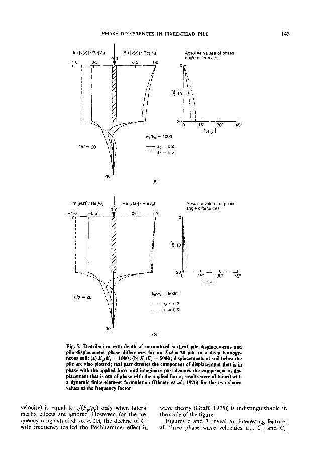
As these results were derived on the basis of an infinitely long bar on dynamic Winkler founda- tion model, it is of interest to show their general validity for piles of finite length supported by a visco-elastic continuum. To this end, a rigorous finite element study was conducted for a pile of slenderness ratio L/d = 20 embedded in a deep homogeneous stratum and having EJE, = 1000 or 5000. Fig. 5 shows the distribution along the length of the pile of the real and imaginary parts of the vertical pile displacement, u = u(z), for the same two values (0.2 and 0.5) of the frequency factor a,. Evidently, the imaginary and real com- ponents of the displacement as well as the resulting phase angle remain almost constant with depth; hence, the phase differences between various points along the pile and its head (also plotted in Fig. 5) are very small, and their values are very close to those predicted by the analytical method (Fig. 4). Thus, the analytical results and the hypothesis of synchronous wave emission are largely substantiated. However, in much stiffer soils, for which the moduli ratio EJEs may attain values lower than, say, 300 (e.g. hollow pipe piles in hard soil), the apparent phase velocity C, becomes a smaller multiple of V,, and then for very slender piles (L > 40) phase differences along the pile may reach 40” at higher frequencies. In

142 MAKRIS AND GAZETAS
Phasedifference:degrees
5 10 15 I I I
\ E&F* = 1000
Fig. 4. Phase difference between displacements at depth z and at pile top for two values of the frequency factor
such cases the assumption of synchronous emis- sion might not be applicable. Dobry & Gazetas (1988) have reported that their simple pile group interaction factor (equation (l)), leads to an over- prediction of pile group effects for values of E,/E, lower than 300.
A further observation can be made on the dis- persion relation of equation (19). While Fig. 3 plots C, for a homogeneous halfspace, in reality, bedrock or at least a stiff rock-like soil layer is likely to exist at some depth below the ground surface. Then the soil deposit is a deep stratum rather than a true halfspace, although a long pile can still be modelled as an infinitely long beam. Below the stratum cutoff frequency u, the pile- soil system radiates very little energy, and c, essentially reflects only the hysteretic material damping in the soil. Without material damping c, = 0, and the solution reduces to the case dis- cussed by Wolf (1985, 1988), in which the phase velocity is indeed infinite (as 6 = 0). Therefore as a first approximation, for w < 0,: C, -+ co. In general, however, the phase velocity is finite pro- vided that a mechanism of energy dissipation exists along the pile (radiation or material damping).
It is also of interest to study the complete evol- ution of the phase wave velocity over an extreme range of frequencies (0 < a, < lo), as shown in
Fig. 6 for a pile with E,/E, = 1000 and in Fig. 7 for a pile with E,JEs = 5000 for two different pile mass densities: pP = 1.4~~ and 0.7~~. The solid curve represents the developed dispersion rela- tion; it is obvious that equations (19) and (22) give the same value for both C, and dCJda, at the characteristic frequency WZ. Also plotted in Figs 6 and 7 are the dispersion relations of two simpler associated systems, namely a semi-infinite rod on elastic-Winkler foundation and a semi- infinite unsupported rod. These two systems have been studied extensively in the wave-propagation literature (e.g. Graff, 1975; Achenbach, 1976), and are obviously particular cases of the pile system studied here (Fig. 2). The phase velocity C, for the rod on elastic foundation is obtained from equations (19) and (22) by setting c, = 0 at all fre- quencies. As discussed by Wolf (1985) and men- tioned above, C, becomes infinite at and below the characteristic frequency W, Therefore
C,=m, ifw<f%, (26a)
WW The phase velocity C, for longitudinal waves in
an unsupported rod (called bar or rod wave
PHASE DIFFERENCES IN FIXED-HEAD PILE 143
I Re Absolute values of phase angle differences
0
I’ \
EdEs = 1000
Ud = 20 Y \: - a” = 0.2 I ---- a, = 0.5
:
Im [WI I ReW
-1.0 -0.5
T-r
4(
EdE, = 5000
- a, = 0.2 ---- a0 = 0.5
(b)
Absolute values of ohase mgle differences
, , I 15” 30” 45
lA$J
Fig. 5. Distribution with depth of normalized vertical pile displacements and pile-displacement phase differences for an L/d = 20 pile in a deep homoge- neous soil: (a) Q./E, = 1000; (b) &,/ES = 5000; displacements of soil below the pile are also plotted; real part denotes the component of displacement that is in phase with the applied force and imaginary part denotes the component of dis- placement that is out of phase with the applied force; results were obtained with a dynamic finite element formulation (Blaney et al., 1976) for the two shown values of the frequency factor
velocity) is equal to J(E,/p,) only when lateral inertia effects are ignored. However, for the fre- quency range studied (a, < lo), the decline of C, with frequency (called the Pochhammer effect in
wave theory (Graff, 1975)) is indistinguishable in the scale of the figure.
Figures 6 and 7 reveal an interesting feature: all three phase wave velocities C,, C, and C,

144 MAKRIS AND GAZETAS
EdE, = 1000
I
0 IA I 1 1 I
200
$100
0 ,L
t W,dlV,
0
ml r/ I
ep/es = 1.4
A I I I I f2
I 4 6 8 10
W,dlV, a, = wd/V,
Fig. 6. Comparison of dispersion relations for three long- Fig. 7. Comparison of dispersion relations for three long- itudinal phase velocities: C,, for a pile supported on itudinal phase velocities: C, , for a pile supported on axial axial springs and dashpots (modelling embedment in springs and dashpots (modelling embedment in halfspace); C,, for a bar on axial springs; CL for an balfspace); Cs, for a bar on axial springs; CL for an unsupported bar-two different values of pile-to-soil mass unsupported bar-two different values of pile-to-soil mass densities ratio; EJE, = 1000 densities ratio; E&E, = 5000
reach identical asymptotic values at high fre- quencies. It appears that at these frequencies pile inertia effects dominate, while the resistance of the supporting springs and dashpots becomes negligibly small in comparison.
LATERAL VIBRATION
Governing equation and solution With regard to lateral excitation, the assump-
tion of an infinitely long pile is quite appropriate even for stiff piles, as their active length is usually smaller than the total pile length. Indeed, for a pile on Winkler foundation, the active length below which the pile deformations are negligible is given by Randolph (1981) as
1, % 4(u)“* N 1.75d(+y4
EdE, = 5000
ede. = 0.7
I
0 IA 1 I I
i I
. G \ ede. = 1.4
I I I I 72
I 4 6 a 10
FL&d/V, a, = codI’/,
where the expression for k, from equation (2~) has been used. For the typical values of E,/E, = 1000 and 5000, the active lengths from equation (27) are only about 10d and 1% respectively. As shown by Krishnan et al. (1983) and Gazetas & Dobry (1984a, 1984b) the concept of the active length is also valid under dynamic harmonic loading, although the exact values of I, are slight- ly larger than those predicted from equation (27). Hence, in most cases, piles respond as infinitely long beams.
The pile is modelled as an Euler-Bernoulli beam, where the effects of rotatory inertia and shear distortion are ignored. The deflected state of the pile and the forces acting on an element are shown in Fig. 2, with u(z, t) denoting the horizon- tal displacement at depth z and time t. Zero slope is imposed at pile head to account for the shape of deformation induced by a horizontally- translating rigid pile cap (fixed-head pile, in

PHASE DIFFERENCES IN FIXED-HEAD PILE 145
geotechnical terminology). For a harmonic steady-state excitation u(z, t) = U(Z) exp (iot), dynamic equilibrium gives
E I d4W - + (k, + iwc, - mw2)u(z) = 0 p p dz4
(28)
The solution to equation (28) is sought separately for the two cases of w < i3, and w > Li,, where w, = (/CX/m)“Z.
First, consider w < I&. This is again the usual range of greatest interest in foundation dynamics, corresponding approximately to a, < 1.8. The solution of equation (28) derived in Appendix 1 takes the form
u(z, t) = ? (( 1 + i) exp (- Rbz)
x exp [i(wt - Raz)]
+ (1 - i) exp (-Raz)
x exp [i(wt + Rbz)]} (29)
where U, = u(O) is the displacement amplitude at the pile head and R, 0, a and b are as given in Appendix 1.
For an applied harmonic load P, exp (iwt) with P, real, U, is complex
u, = Pobl - iy2) Ep 1, R3(yi2 + ~2’)
(30)
where
y1 = -a3 - b3 + 3a2b + 3ab2
yz = a3 - b3 + 3a2b - 3ab2
(3W
(31b)
and a, b are as given in Appendix 1. It can be checked that when w = 0 (i.e. under static loading), a = b = 1, y1 = 4 and y2 = 0; then equation (30) reduces to the familiar static expres- sion
PO U,=- 4E, Ip 1’ (32)
with I (from Appendix 1) being simply equal to the static value (Elson, 1984)
1 = (k,,‘4E, 1p)1’4 (33)
The first term in the parentheses in equation (29) corresponds to a downwardly propagating wave and the second term to an upwardly propa- gating wave, both with amplitude decaying expo- nentially as with z. It should be emphasized that the two waves coexist and the displacement dis- tribution along the pile should always be regard- ed as the superposition of both. Nevertheless, the phase velocity of each wave separately can be
identified, giving a dual dispersion relation
“‘=R(cos{+sin~) (34a)
“=R(coscsin$ (34b)
Second, consider w > cc,, which translates approximately to n, > 1.8, a frequency range of less practical interest, which is examined here as providing insight into asymptotic behaviour at high frequencies. Following a similar procedure to the one already outlined, gives the solution
u(z, t) = ?{(I •t i) exp (- Rqz) exp [i(wt - Rpz)]
+ (1 - i) exp (- Rpz) exp [i(wt + Rqz)]}
(35)
where
R= (mu2 - kJ2 + (WC.J~ I’*
(E, I,)’ 1 (36)
p = cos $ > 0, e
q= -sin;>0 (37)
and B is given by the same expression as for the case w < 6, (given in Appendix I), but now takes a negative value (- 7r/2 < 6 < 0). Again, the solu- tion is a superposition of two waves, one propa- gating downwards and one propagating upwards, with respective phase velocities
c,L =w
R cos f (38a)
C,f= w
-Rsin$ (3W
In the completely hypothetical case of c, = 0, one would have 0 =0, p= 1, q =0, R = (mw2 - kJE,I) , ‘I4 = 1. and equation (36) would
reduce to
u(z, t) = + = ((1 - i) exp (--AZ) exp (iwt)
+ (1 + i) exp [i(wt - AZ)]} (39)
In this case only down-going waves exist, as the term corresponding to incoming waves reduces to a decaying exponential.

146 MAKRIS AND GAZETAS
DISCUSSION From equations (34) and (38), the phase velo-
cities C,l and Cat of the direct (down-going) and reflected (up-coming) waves are shown as solid lines in Figs 8 and 9, over a wide range of the frequency factor 0 < n, < 10. Also plotted in Figs 8 and 9 are the frequency-dependent phase velo- cities of a semi-infinite beam on the elastic- Winkler foundation (Cw), and a semi-infinite unsupported flexural beam Cr. These two cases are recovered from the developed formulation for c, = 0 and k, = c, = 0, respectively. The corre- sponding phase velocities are
C,=co, ifw<i3, (40a)
ede. = 0.7
0 I I I 1 A 0 j2 4 6 8 10
W,dlV, a, = wdlV,
Fig. 8. Phase wave velocities of beams in lateral harmo- Fig. 9. Phase wave velocities of beams in lateral harmo- nic oscillations; tbe two solid lines are for the up-going nic oscillations: the two solid linea are for the up-going sod down-going waves in a pile oa lateral springs and and down-going waves in a pile on lateral springs and dashpots (modelling embedment in halfspace); Cw is for dasbpots (modelling embedment in halfspace); C, is for a flexoral beam on lateral springs; C, is for an unsup a flexural beam oo lateral ‘spriogs’; C, is for ao ansop- ported flexoral beam-two ditTerent values of pile-to-soil ported flexoral beam-two different values of pile-to-soil mass densities ratio; E,/E, = 1000 mass densities ratio; E&E, = SO00
Ja0 c,=v+- + ( >
l/4
13 (41)
where f, = 1.2 and f2 = 6~,ai/~ + 2fifl. The following trends are worthy of note. The presence of material and geometric
damping in the pile-soil system has a highly sig- nificant effect on the nature of propagating waves and the phase velocities. As mentioned above, an upward propagating (reflected) wave is generated only in the damped system. Moreover, at the low frequency range of usual interest (a, < I), while the phase velocity becomes infinite in the undamped case Cw, both C,l and C,t achieve very small values and, in fact, tend to zero with decreasing frequency. Hence the presence of a rigid soil layer or rock at a shallow depth that would create a cutoff frequency w,, below which
@de, = 1.4
W,dlV, a, = wd/V,

PHASE DIFFERENCES IN FIXED-HEAD PILE 147
radiation damping diminishes, deserves attention. In such a case, if soil and pile material damping are ignored, then c, = 0, 0 = 0, a = b = 1, R = (k, - mw2/4E, IJ 1/4 = 1 (real number), and equa- tion (29) simplifies to
u(z, t) = U, e-“‘(sin lz + cos AZ) eiwt (42)
which describes a standing wave and is identical in form to the static solution (Scott, 1981), to which it reduces for w = 0. Hence, in this case there are no propagating waves (infinite apparent phase velocity) and all points move in phase, although with an amplitude decreasing exponen- tially with depth, in accordance with the behav- iour of the elastically restrained beam (equation (42)) already described.
The phase velocity C,l of the downwardly pro- pagating wave in the pile remains very close to the velocity C, of the (unsupported) flexural beam for all but the very low frequencies. Nevertheless, it is perhaps surprising that C,’ is much closer to C, than to C,.,. Hence, neglecting radiation and material damping may adversely affect even the nature of the solution.
The phase velocities of the three downwardly propagating waves, namely Cal in the pile, C, in the elastically-restrained beam and C, in the flex- ural beam, converge to a single curve at high fre- quencies (say a, > 3), and tend to infinity by growing in proportion to ,/a. However, the velocity C,’ of the reflected wave in the pile soon diverges significantly and tends to infinity as a power of o. That the phase velocities grow without limit with increasing frequency is an inac- curacy attributed to neglecting rotatory inertia and shear distortion effects. Such effects must be included in the formulation if more correct values are to be obtained for phase velocities at very high frequencies.
No clear conclusions can be drawn from Figs 8 and 9 regarding the assumption of synchronous wave emission from a laterally oscillating pile. Both C,l and Cat attain relatively small values, of about 2-5 V,, in the frequency range of greatest interest, even for a relatively stiff pile (EJE, = 5000). It seems that the only way to assess the significance of such wave velocities is to examine the phase differences among lateral displacements along the pile.
1.2
r
0.8 h
Fixed-head pile
zid
Fig. 10. Variation with depth of phase diierences and normalized lateral deflexion amplitudes at two frequency factors
Fig. 11. Variation with depth of phase differences and normalized lateral deflexion amplitudes at two frequency factors

148 MAKRIS AND GAZETAS
To this end, the phase of the motion at a par- ticular depth z in time t is computed from
and for z equal to zero the phase becomes
The phase difference between the motion at depth z and the motion at the head of the pile
A+ = or - I$(z, t) (45)
is plotted in Figs 10 and 11 as a function of z/d for two values of the dimensionless frequency a, (0.2 and 0.5) for EJES = 1000 and 5000. It is clear that phase differences remain quite small up to a certain depth, beyond which they increase rapidly, especially at higher frequencies. Figs 10 and 11 also show the normalized amplitude of pile displacements plotted against z/d. It is evident that, strictly speaking, the assumption of simultaneous emission is not valid. Nevertheless, it is also clear that phase differences become sub- stantial only at relatively large depths where the displacement amplitude has decreased signifi- cantly; thus waves emitted from such depths would have a negligible amplitude and their phase differences would be of little, if any, conse- quence to adjacent piles. Hence, the error intro- duced by assuming synchronous wave emission along the pile would in most cases be acceptable. This may explain the successful performance of the method developed by Dobry & Gazetas (1988), Makris & Gazetas (1992), and Gazetas & Makris (1991), as shown in Fig. 1.
CONCLUSIONS Axial vibrations
When an infinitely long pile embedded in a realistic dynamic-Winkler model of a homoge- neous halfspace is subjected to axial harmonic head loading, it undergoes steady-state oscil- lations due to a compression-extension wave that propagates downwards with amplitude decaying exponentially with depth, and a frequency- dependent phase velocity C, (dispersive system).
In the frequency range of greatest interest in foundation dynamics (0.2 ,< a, < 0+3), C, initially increases with frequency and for typical real-life piles achieves quite large values compared to the S-wave velocity in soil V,. As a result, phase dif- ferences between displacements along the oscil- lating pile are very small and can be neglected in approximate studies of through-soil interaction between two adjacent piles-a conclusion for
which additional (direct and indirect) supporting evidence is provided in this Paper.
In the frequency range of interest considered, the wave velocity C, of a bar elastically restrained solely by Winkler springs is infinite. However, C, could approach infinity only at frequencies below a possible stratum cutoff frequency (when radi- ation damping vanishes) if all material hysteretic damping were ignored.
At high frequencies (a, x 5-lo), C, , C, and the (unsupported) bar wave velocity C, reach the same asymptotic value, equal to about J(EJp,) (lateral inertia Pochhammer effects are not as yet discernible).
Lateral vibrations During lateral steady-state oscillation under
harmonic fixed-head horizontal leading, two waves develop in the pile: a downwardly propa- gating (direct) wave with phase velocity C,l, and an upwardly propagating (reflected) wave with different phase velocity C,f-both having ampli- tude decaying exponentially with depth.
The two phase velocities C,l and Cat increase monotonically with frequency, the latter at a much faster rate. In the frequency range of great- est interest they both attain very low values, only a few times larger than V, in the soil but smaller than C, (the phase velocity of an unsupported flexural beam).
In contrast to the spring-and-dashpot sup- ported pile, only one downwardly propagating wave develops in a beam supported solely on springs. Moreover, the phase velocity C, in the latter is infinitely large below the characteristic frequency W, = J(kJm), i.e. in the frequency range of greatest interest. Therefore, ignoring the material and especially the radiation damping generated by the soil-pile system would change the nature of the wave propagation in laterally oscillating piles.
Despite the relatively low values of C,l and Cat at 0 < a,, < 1.8, the two waves (direct and reflected) combine in such a way that phase differ- ences between pile deflexions at various depths remain quite small along the upper, most active, part of the pile. Such differences increase con- siderably at greater depths, but this has only a minor effect on how wave energy is radiated from a pile: this observation is significant in the behav- iour of pile groups. An exception to this behav- iour, however, must be noted: with hollow pipe piles in hard soils, for which EJE, < 300, phase differences may become appreciable and the assumption of synchronous emission might lead to a slight overprediction of pile to pile inter- action factors.

PHASE DIFFERENCES IN FIXED-HEAD PILE 149
The phase velocities of the three downwardly propagating waves C,, C, and C, converge to a single curve at high frequencies (a, > 3), while growing in proportion to Jw.
The results presented may lead to an improved understanding of wave propagation phenomena in piles, and find applications in geotechnical problems involving pile dynamics.
APPENDIX 1. SOLUTION OF EQUATION (28) FOR w < 6,
To obtain the solution of equation (28), first substi- tute
4,P = k, + iwc, - mw’
%I, (46)
and then apply the Laplace transform (to accommodate the boundary conditions directly)
L d‘W [-]+4PLC.(z),=O
dz4
Denoting the Laplace transform of u(z) by Is(s) = L[u(z)] and using standard Laplace transform properties, equa- tion (47) becomes an algebraic equation in the trans- formed space
f-J(s) = u’“(0) & + u”(0) -.A- s4 + 4P
S3
+ u(O) - s4 + 4P
(48)
where the prime denotes derivative with respect to z. Applying the inverse Laplace transform and intro-
ducing Euler’s complex notation leads to the following solution, with the boundary conditions at z = 0 incor- porated as unknowns
u(z) = - i[exp (iRaz) exp (Rbz)
- exp (-iRbz) exp (Roz)][$ + $1
- i[exp (iRbz) exp (-Raz)
-exp(-iRnz)exp(Rbz)][$-$1
+ [exp (iRaz) exp (Rbz)
W + exp (- iRbz) exp (Raz)] - 2 + y 1 + [exp (iRbz) exp (- Raz)
- exp (-iRaz) exp (-Rbz)][z + y] (49)
To ensure a finite displacement amplitude as z tends to infinity
(504
VW
Using these expressions and exp (iwt) leads finally to
u(z, t) = : {(l + i) exp (-iRbz) exp [i(ot - Raz)]
+ (1 - i) exp (-Raz) exp [i(ot + Rbz)]} (51)
where
R = (kx - mw2)’ + (wc,)* “*
(4R, 1,)’ 1 ’
o<e<q
(52)
(53)
a = cos % + sin $ > 0, b = cos $ - sin % > 0 (54)
NOTATION a, = wd/v,
A, c,
c,
C,
G1
C,’
CE
cw
d
E,, Es
1: kx
k,
m
dimensionless frequency cross-sectional area of pile distributed dashpot constant per unit pile length for soil reaction against pile lateral motion (equation (2d)) distributed dashpot constant per unit pile length for soil reaction against pile verti- cal motion (equation (2b)) phase velocity of wave propagating in an infinite rod supported by visco-elastic foundation and subjected to axial vibra- tion phase velocity of down-going wave pro- pagating in an infinite flexural beam sup- ported by visco-elastic foundation and subjected to lateral vibration phase velocity of up-coming wave propa- gating in an infinite flexural beam sup- ported by visco-elastic foundation and subjected to lateral vibration phase velocity of wave propagating in an infinite rod supported by elastic (Winkler) foundation and subjected to axial vibra- tion phase velocity of wave propagating in an infinite unsupported flexural beam sub- jected to lateral vibration phase velocity of wave propagating in an infinite unsupported rod subjected to axial vibration (longitudinal waves) phase velocity of wave propagating in an infinite flexural beam supported by elastic (Winkler) foundation and subjected to lateral vibration pile diameter Young’s moduli of pile and soil imaginary unit J( - 1) cross-sectional moment of inertia of pile distributed spring constant per unit pile length for soil reaction against pile verti- cal motion (equation (2c)) distributed spring constant per unit pile length for soil reaction against pile verti- cal motion (equation (2a)) distributed mass per unit length of pile

150
P, exp (ion)
r 0
:
u(s, t)
U, exp (ion) 4% t)
V, exp (id)
K B
A4
MAKRIS AND GAZETAS
harmonic load at the pile head pile radius independent variable in Laplace space axis-to-axis distance between interacting piles horizontal pile displacement
harmonic displacement of the pile head vertical pile displacement harmonic vertical displacement of the pile head S-wave velocity in soil damping ratio of the soil phase difference between the motion at depth z and the motion at the pile head at a specific time wave number (equation (44) or (47)) Poisson’s ratio of the soil phase of the pile motion at a particular depth z at time t circular frequency of oscillation stratum cutoff frequency in vertical (compression-extension) vibrations stratum cutoff frequency in horizontal (shear) vibrations characteristic frequency in horizontal (lateral) vibration, J(kJm) characteristic frequency in vertical (axial vibration, J(kJm)
REFERENCES Achenbach, J. D. (1976). Wave propagation in elastic
solids. North-Holland. Blaney, G. W., Kausel, E. & Roesset, J. M. (1976).
Dynamic stiffness of piles. Proc. 2nd Int. Co& Numer. Meth. Geomechan. Blacksburg 2, 100-1012.
Dobry, R. 8z Gazetas, G. (1988). Simple method for dynamic stiffness and damping of floating pile groups. Geotechnique 38, No. 4, 557-574.
Dobry, R., Vicente, E., O’Rourke, M. J. & Roesset, J. M. (1982). Horizontal stiffness and damping of single piles. J. Geotech. Engng Am. Sot. Civ. Engrs 108, GT3,4399459.
Elson, W. K. (1984). Design of laterally loaded piles. Report 103. London: Construction Industry Research Information Association.
Gazetas, G. (1987). Simple physical methods for founda- tion impedances. Dynamic behavior of foundations and buried structures. P. K. Banerjee & R. Butter- field (eds), pp. 45593. London: Elsevier.
Gazetas, G. & Dobry, R. (1984a). Horizontal response of piles in layered soils. J. Geotech. Engng Am. Sot. Civ. Engrs 110,20-40.
Gazetas, G. & Dobry, R. (1984b). Single radiation damping model for piles and footings. J. Engng Mech. Am. Sot. Civ. Engrs 110, No. 6,937-956.
Gazetas, G. & Makris, N. (1991). Dynamic pilesoill pile interaction I: analysis of axial vibration. Earth- quake Engng Struct. Dyn. 20, No. 2, 115-132.
Graff, K. F. (1975). Waue motion in elastic solids. Columbus: Ohio State University Press.
Kagawa, T. & Kraft, L. M. (1980). Lateral load-
deflection relationship of piles subjected to dynamic loadings. Soils & Fdns 20, No. 4, 19-36.
Kaynia, A. M. & Kausel, E. (1982). Dynamic stiffness and seismic response of pile groups. Research Report R82-03. Cambridge, Massachusetts: Massachusetts Institute of Technology.
Krishnan, R., Gazetas, G. & Velez, A. (1983). Static and dynamic lateral deflections of piles in non- homogeneous soil stratum. Giotechnique 33, No. 3, 307-325.
Liou, D. D. & Penzien, J. (1979). Mathematical model- ling of piled foundations. Numerical methods in off- shore piling, pp. 67-74. London: Institution of Civil Engineers.
Makris, N., Gazetas, G. & Fan, K. (1989). Analytical results for pile-soil-pile interaction in vertical har- monic motion. Proceedings of conference on earth- quake resistant construction and design, Berlin, S. A. Savidis (ed.) Rotterdam: Balkema.
Makris, N. & Gazetas, G. (1992). Dynamic pile-soil- pile interaction II: lateral and seismic response. Earthquake Engng Struct. Dyn. 20, No. 2, 145-162.
Nogami, T. (1983). Dynamic group effect in axial responses of grouped piles. J. Geotech. Engng Div. Am. Sot. Ciu. Engrs 109, GT2,228-243.
Novak, M. (1974). Dynamic stiffness and damping of piles. Can. Geotech. J. 11, No. 4, 574-598.
Novak, M. (1977). Vertical vibration of floating piles. J. Engng Mech. Div. Am. Sot. Civ. Engrs 103, No. 1, 153-168.
Novak, M. (1979). Soil-pile interaction under dynamic loads. Numerical methods in offshore piling, pp. 59-74. London: Institution of Civil Engineers.
Novak, M. (1985). Experiments with shallow and deep foundation. Vibration Problems in Geotechnical Engineering, G. Gazetas & E. Seling (eds), pp. l-26. New York: American Society of Civil Engineers.
Novak, M., Nogami, T. & Aboul-Ella, F. (1978). Dynamic soil reaction for plane strain case. J. Enyng Mech. Div. Am. Sot. Ciu. Engrs 104, No. 4, 1024- 1041.
Randolph, M. F. & Wroth, C. P. (1978). Analysis of deformation of vertically loaded piles. J. Geotech. Engng Div. Am. Sot. Civ. Engrs 104, 146551488.
Randolph, M. F. & Wroth, C. P. (1979). An analysis of the vertical deformation of pile groups. Geotechnique 29, No. 4,4233439.
Randolph, M. F. (1981). The response of flexible piles to lateral loading. Ghotechnique 31, No. 2,247-259.
Roesset, J. M. (1984). Dynamic stiffness of pile groups. Pilefoundations, pp. 263-286. New York: American Society of Civil Engineers.
Roesset, J. M. & Angelides, D. (1980). Dynamic stiffness of piles. Numerical methods in offshore piling, pp. 75-82. London: Institution of Civil Engineers.
Scott, R. F. (1981). Foundation analysis. London: Prentice-Hall.
Wolf, J. P. (1985). Dynamic soil-structure interaction. London: Prentice Hall.
Wolf, J. P. (1988). Soil-structure interaction in the time- domain. London: Prentice Hall.
Wolf, J. P. (1992). Cone models for pile foundation. Piles under dynamic loading, S. Prakash (ed.), New York: American Society of Civil Engineers.