Embed Size (px)
Citation preview

TECHNICAL GUIDE: TECHNICAL GUIDE: APF2.8
The unique solution for flexibility in flanged pipework systems.
Dismantling Joint
Applications
Pump chambers
Valve chambers
Flow metering stations
Allows pipeline adjustment during
assembly
Product Attributes
Pre-assembled for ease of installation
Corrosion protective finishings.
Stainless steel studs, bolts, washers
and tie bars
Approvals/Standards
WRAS approved for use in drinking
water
Quality
ISO 9001 Manufacturing

AP
F2
.8 P
iPe
mA
te
DiS
mA
nt
lin
g J
oin
t |
VA
LVE
S &
HY
DR
AN
TS
| P
G 2
PIPEMATE Flange Restrained Dismantling Joint has been developed
to provide flexibility in flanged pipework systems at the design and
installation stages. The PIPEMATE Flange Restrained Dismantling Joint is available in welded steel as standard in any nominal size from 50mm upwards and can be fabricated to suit any flange drilling, must be installed above ground and/or in a chamber. Standard sizes and dimensions can be obtained from PIPEMATE in order for this joint to be specified within a project design.
Applications
■ Designed for flanged pipe systems requiring longitudinal restraint and the need to be disassembled. Pressure water systems requiring end restraint allowing approximately 50 mm flange to flange movement.
Features
■ A flange adaptor, flanged spigot piece and optional tie bars/bolts.
■ Two flanged spigot pieces, a loose flange and full set of tie-bars/bolts.
■ Fusion Bonded Epoxy (FBE)
Product Attributes
■ Eliminates the need for more complex anchoring systems.
■ Excellent method of providing a demountable joint in an otherwise flanged pipework systems.
■ Corrosion Protection. The Flange Restrained Dismantling Joint will be coated standards with Fusion Bonded Epoxy (FBE). Other coatings will be available on request.
materials and Relevant Standards
Flange Adaptor Body
■ Steel To BS EN 10025 S275
gasket
■ Rubber to BS EN 681-1 or to suit service
end Ring
■ Steel to BS EN 10025 S275 or Ductile Iron to BS EN 1563 Gr450/10
Flange Spigot
■ Steel To BS EN 10025 S275
Studs
■ Galvanized Steel/Stainless
tie Bolts
■ Steel Galvanized Steel/Stainless Steel
Type A
Type A
Type B
Type B

AP
F2
.8 P
iPe
mA
te
DiS
mA
nt
lin
g Jo
int
| VA
LVE
S &
HY
DR
AN
TS
| PG
3
type A Dismantling Joint Dn150 to Dn1000
Design Specification
a. Flange: Steel to BS EN 10025:1993 Grade S275 or equivalent
b. End Flange & Flange Sleeve: Rolled Steel to BS EN 10025:1993 Grade S275 or equivalent
c. Finishing: Fusion Bonded Epoxy Powder Coated Coated Approx. 300 microns thick (Black)
d. Studs, Nuts & Washers: Stainless Steel SS 316
e. Tie Bars & Nuts: Stainless Steel SS 316
f. Sealing Ring: NBR to BS EN 681-1 Type 'WA'
g. Flange Drilling: AS 4087 Class 16
h. Working Pressure: 16 Bar
tABle 1
Flange Details Flange to Flange Details tie Bar Details
Dn Ø D K t Flange Drilling maximum length
(mm)
minimumlength
(mm)
nominal length
(mm)
no. of tie Bars
Ø x length of tie Bars
Volume (m3)
Weight (kg)
no. of Holes
Ø Holes
150 280 235 15 8 18 220 170 195 v4 M16 x 320 0.025 19.2
200 335 292 20 8 18 250 200 225 4 M16 x 340 0.038 28.9
225 370 324 20 8 18 250 200 225 4 M16 x 340 0.047 36.0
250 405 356 20 8 22 250 200 225 4 M20 x 370 0.061 45.5
300 455 406 23 12 22 250 200 225 4 M20 x 370 0.077 54.5
350 525 470 25 12 26 260 210 235 4 M24 x 410 0.113 74.3
375 550 495 25 12 26 260 210 235 4 M24 x 410 0.124 78.7
400 580 521 25 12 26 300 250 275 6 M24 x 460 0.155 92.1
450 640 584 25 12 26 300 250 275 6 M24 x 460 0.188 104.5
500 705 641 25 16 26 300 250 275 8 M24 x 460 0.229 122.9
600 825 756 25 16 30 320 270 295 8 M27 x 480 0.327 157.9
700 910 845 25 20 30 320 270 295 10 M27 x 510 0.422 179.2
750 995 927 25 20 33 320 270 295 10 M33 x 510 0.505 227.1
800 1060 984 25 20 36 340 290 315 10 M33 x 540 0.607 248.8
900 1175 1092 25 24 36 340 290 315 12 M33 x 560 0.773 302.1
1000 1255 1175 25 24 36 360 310 335 12 M33 x 590 0.929 311.6
AP
F2
.8 P
iPe
mA
te
DiS
mA
nt
lin
g J
oin
t |
DR
AIN
AG
E C
HA
NN
EL
| P
G 4
Disclaimer: While every effort has been made to ensure that the information in this document is correct and accurate, users of Hygrade Water Infrastructure product or information within this document must make their own assessment of suitability for their particular application. Product dimensions are nominal only, and should be verified if critical to a particular installation. No warranty is either expressed, implied, or statutory made by Hygrade Water Infrastructure unless expressly stated in any sale and purchase agreement entered into between Hygrade Water Infrastructure and the user. october 2021
Scan for more information
BRISBANE (Head Office)42-44 Blue Eagle DriveMeadowbrook, QLD 4131
SYDNEY10 McPherson RoadSmeaton Grange, NSW 2567
+61 7 38059186hygradewater.com.au
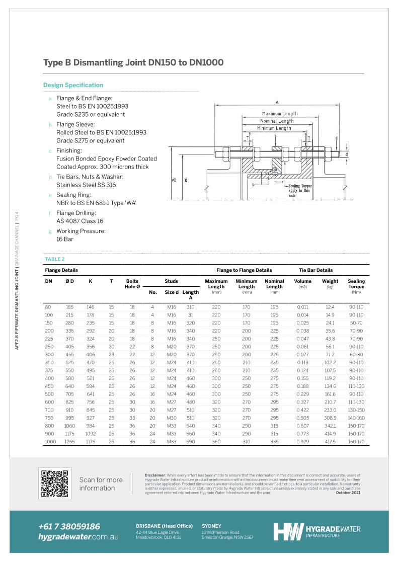
type B Dismantling Joint Dn150 to Dn1000
Design Specification
a. Flange & End Flange: Steel to BS EN 10025:1993 Grade S235 or equivalent
b. Flange Sleeve: Rolled Steel to BS EN 10025:1993 Grade S275 or equivalent
c. Finishing: Fusion Bonded Epoxy Powder Coated Coated Approx. 300 microns thick
d. Tie Bars, Nuts & Washer: Stainless Steel SS 316
e. Sealing Ring: NBR to BS EN 681-1 Type 'WA'
f. Flange Drilling: AS 4087 Class 16
g. Working Pressure: 16 Bar
tABle 2
Flange Details Flange to Flange Details tie Bar Details
Dn Ø D K t Bolts Hole Ø
Studs maximum length
(mm)
minimumlength
(mm)
nominal length
(mm)
Volume (m3)
Weight (kg)
Sealing Torque
(Nm)no. Size d length A
80 185 146 15 18 4 M16 310 220 170 195 0.011 12.4 90-110
100 215 178 15 18 4 M16 31 220 170 195 0.014 14.9 90-110
150 280 235 15 18 8 M16 320 220 170 195 0.025 24.1 50-70
200 335 292 20 18 8 M16 340 220 200 225 0.038 35.6 70-90
225 370 324 20 18 8 M16 340 250 200 225 0.047 43.8 70-90
250 405 356 20 22 8 M20 370 250 200 225 0.061 55.1 90-110
300 455 406 23 22 12 M20 370 250 200 225 0.077 71.2 60-80
350 525 470 25 26 12 M24 410 250 210 235 0.113 102.2 90-110
375 550 495 25 26 12 M24 410 260 210 235 0.124 107.5 90-110
400 580 521 25 26 12 M24 460 300 250 275 0.155 119.2 90-110
450 640 584 25 26 12 M24 460 300 250 275 0.188 134.6 110-130
500 705 641 25 26 16 M24 460 300 250 275 0.229 161.6 90-110
600 825 756 25 30 16 M27 480 320 270 295 0.327 210.7 110-130
700 910 845 25 30 20 M27 510 320 270 295 0.422 233.0 130-150
750 995 927 25 33 20 M30 510 320 270 295 0.505 308.9 140-160
800 1060 984 25 36 20 M33 540 340 290 315 0.607 342.1 150-170
900 1175 1092 25 36 24 M33 560 340 290 315 0.773 414.9 150-170
1000 1255 1175 25 36 24 M33 590 360 310 335 0.929 417.5 150-170