Embed Size (px)
Citation preview

Disket-Nanorings of K2Ti6O13 Formed by Self-Spiraling of a Nanobelt
Cheng-Yan Xu,†,‡,§ Yu-Zi Liu,†,§ Liang Zhen,‡ and Zhong Lin Wang*,†
School of Materials Science and Engineering, Georgia Institute of Technology, Atlanta, Georgia 30332,and School of Materials Science and Engineering, Harbin Institute of Technology, Harbin 150001, China
ReceiVed: March 12, 2008; ReVised Manuscript ReceiVed: April 1, 2008
Single-crystal K2Ti6O13 nanorings were prepared by molten salt synthesis. The nanoring is formed by loop-by-loop winding of a K2Ti6O13 nanobelt by coherently matching the lattice at the edges of the nanobelt in thesame plane. The driving force for such a perfect match at the edges is suggested to minimize the localelectrostatic energy introduced by the cations and anions.
Introduction
Free-standing nanorings, as a new nanostructure for someoxides, have attracted intense interest since their first discoveryin piezoelectric ZnO.1 The wurtzite structure of ZnO producespositively charged (0001)-Zn and negatively charged (0001j)-Opolar surfaces, resulting in a normal dipole moment andspontaneous polarization. Minimizing the electrostatic interac-tion energy is the driving force for the self-coiling process of apolar nanobelt to form a “single-crystal” nanoring as well astheir various derivations such as nanohelixes and nanosprings.2
The spontaneous polarization-induced growth process was alsoapplied for the interpretation of the formation of other wurtzite-structured nanorings, such as AlN nanorings,3 GaN nanorings,4
and also other nonwurtizite-structured nanorings, for example,CuO5 and Ag2V4O11
6 with monoclinic structure and Ba1+x-V6O16 ·nH2O with hewettite structure.7 As to the synthesisroutes, the reported approaches to the preparation of self-coiled,free-standing nanorings were limited to solid-vapor or solutionphase processes. No report on the solid-state synthesis of free-standing nanorings could be found.
In this paper, we report the first discovery of K2Ti6O13 disket-nanorings formed by self-spiraling of a K2Ti6O13 nanobelt,which was prepared by molten salt synthesis (MSS). Thestructure of the nanoring has been characterized, and thenanoring is formed by loop-by-loop winding of a K2Ti6O13
nanobelt by coherently matching the lattice at the edges of thenanobelt in the same plane. The driving force for such a perfectmatch at the edges is suggested to minimize the local electro-static energy introduced by the cations and anions.
Experimental Section
Synthesis. Single-crystalline K2Ti6O13 nanorings were pre-pared by molten salt synthesis method, which is similar to ourprevious report on the synthesis of other alkali titanate andniobate nanowires/nanoribbons.8 First, 0.046 g of K2C2O4
(Aldrich), 0.04 g of TiO2 (anatase, Aldrich) nanoparticles,9 and
2.0 g of KCl were mixed with ∼5 mL of Tetrogi NP-9 (Aldrich)and ground for 10 min. Then, the mixture was placed in acombustion boat and annealed in a tube furnace at 800 °C for3 h and subsequently cooled naturally to room temperature. Theresulted powders were washed with distilled water several timesto remove remaining KCl and K2C2O4.
Characterization. X-ray diffraction (XRD) patterns werecollected using a Philips X’pert diffractormeter with high-intensity Cu KR irradiation (λ ) 1.5406 Å). Morphology ofthe nanorings was characterized by scanning electron microscope(SEM, LEO 1530). High-resolution transmission electron mi-croscope (HRTEM) observations were carried out on a JEOL4000EX microscope at accelerating voltage of 400 kV. Energy-dispersive X-ray spectroscopy (EDS) analysis was conductedby using a Hitachi HF2000 microscope. Crystal structure modeof K2Ti6O13 was built by using MSI CERIUS2 software.
Results and Discusssion
Figure 1a shows an overview of the as-synthesized product,which consists of a wealth of nanobelts, platelets as well asmany free-standing nanorings. The rings have typical diametersof ∼1 to 5 µm and wall thickness of several hundreds nano-meters. High-magnification SEM image (Figure 1b) clearlyshowed a perfect circular shape of the complete ring. XRDrevealed that the as-synthezied product including the nanoringsis a single phase K2Ti6O13 (Figure 1c) with lattice parametersa ) 15.59, b ) 3.796, c ) 9.108 Å, and � ) 99.78° (JCPDS40-0403). Through the magnified SEM images presented inFigures 1b,d, the nanoring is clearly a result of windingnanowire/nanobelts around its circumferences loop by loop. Thenonuniform contrast indicates the variation in the morphologyin the disket surface.
HRTEM was used for further study of the microstructure andmorphology of the nanorings. Figures 2a,b display a representa-tive bright-field TEM image and corresponding dark-field imageof a nanoring at low magnification. The nonuniform contrastin around the nanoring indicates the presence of strain and latticedistortion. The chemical composition of a nanoring is bestdetermined by EDS in TEM, which was acquired at 200 kVusing a Hitachi HF2000 microscope, as shown in the inset inFigure 2a, clearly showing the presence of the desired elements
* To whom correspondence should be addressed. Fax: 1-404-894-8008.Phone: 1-404-894-8008. E-mail: [email protected].
† Georgia Institute of Technology.‡ Harbin Institute of Technology.§ Both authors contributed equally to this paper.
7547
10.1021/jp802152k CCC: $40.75 2008 American Chemical Society
Published on Web 04/23/2008
2008, 112, 7547–7551

in the sample. Selected-area electron diffraction patterns takenfrom different parts of the nanoring and labeled c, d, and e, aregiven in Figure 1 panels c, d, and e, respectively. The diffractionpatterns are identical except that they rotate following the localtangential orientation of the nanoring. The ring apparently hasa “single-crystal” structure. Indexing of the electron diffractionshows that the normal direction of the disket ring is [001]; thenanobelt that forms the ring has a growth front plane of (010)and side surfaces (100). The nanoring is formed by spiralingthe nanobelt by matching the (200) sides surfaces. The growthdirection of the nanobelt is in agreement with previouslyreported K2Ti6O13 nanowires.10
The loop-by-loop self-spiraling of the nanobelt is directlydepicted by high-magnification TEM image along the ring, asshown in Figure 3a, where the radial contrast is apparent andthe width of the nanobelt remains fairly constant during thespiraling. The number of loops of this nanobelt is ∼65. Bycarefully examining the most inner loop and most outer loop,we did find the starting end (Figure 3b) and finishing end (Figure3c) of the nanobelt of width ∼6 nm. This is solid evidence that
shows that the disket nanoring was made by loop-by-loopwinding of a nanobelt in the ring plane.
The spiraling of K2Ti6O13 nanorings is different from that ofpreviously reported ZnO nanorings, of which the spiralingfollows the “slinky” spring and usually introduces a small helicalangle.1 As to the K2Ti6O13 nanorings, the spiraling of nanobeltis the in-plane spiraling.
The detailed structure at the interface between the twoconsecutive loops of the spiraling nanobelt has been revealedby high-resolution TEM. As guided by the low-magnificationTEM image, we were able to track the location of the interface.Shown in Figure 3d is a HRTEM image that shows the latticeimage of several periods of the spiraling nanobelts. The imageclearly shows the single crystal structure, although the possiblewaving contrast introduced by the “buckling” can be identified.By selecting a region as indicated by a rectangle around aninterface between the two consecutive loops, the details of theinterface is presented in Figure 3e. Using the standard crystalstructure model of K2Ti6O13 and following the orientationrelationship as provided by the electron diffraction, the [001]
Figure 1. (a) SEM image of the as-received synthesized product. (b) A free-standing K2Ti6O13 nanoring. (c) XRD pattern received from thesample to confirm the crystal structure. (d) An enlarged SEM image of a segment of the nanoring shown in panel b, displaying the looping morphologyof the nanoring.
7548 J. Phys. Chem. C, Vol. 112, No. 20, 2008 Letters

orientation simulated HRTEM image is inset in the image. Thesimulated HRTEM of K2Ti6O13 with a 20 period unit cells in caxis was performed using MSI CERIUS2 software with systemdefault JEOL 4000EX microscope under defocus of 143.88 nm.By comparing the simulated image with the experimentalobserved one, the interface shows a “perfect” coherent matchwithout stacking faults, which means that the consecutive loopsof the nanobelt form a perfect lattice and there is no interface.
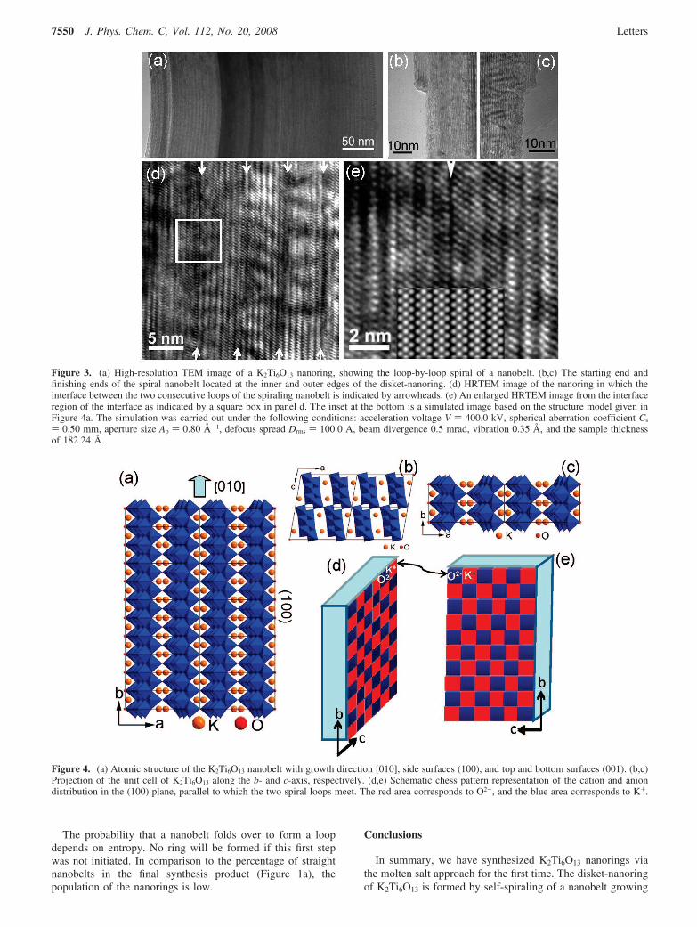
To understand the formation of the coherent interface andthe driving force for forcing the nanobelt to spiraling, we nowexamine the atomic structure of the nanobelt. MonoclinicK2Ti6O13 has a tunnel structure, which is formed by connectingcorners of opposing octahedra from adjacent layers composedby edge-sharing TiO6 octahedrons (see Figure 4a). Potassiumions are situated in the rectangle tunnels. When the nanobeltgrows along [010], its top and bottom surfaces are ((001), andthe two side surfaces are ((100), which requires the cleavageof two adjacent layers, and thus the closed frameworks em-bedding potassium ions are separated ones at each side surface(Figure 4a). The K atoms appear in pairs, but they are displacedwith respect to each other along the c-axes (Figure 4b). In sucha case, the local surface is made of alternative distribution ofK+ and O2- in the form of chess pattern along both b- and c-axes in the (100) plane (Figure 4d). The K+ ion is located inthe channel and the O2- ions is at the apex of the octahedron.
After the nanobelt runs for a full loop and at the interfacingregion, the two side surfaces of the same nanobelt will meetand combine. The most natural way is to match the twointerfaces with the K+ at one side surface directly facing theO2- at the other side surface, which is schematically shownusing the chess pattern in Figure 4d. If the surface structure isperfect as we have described in Figure 4a, such a matching asdepicted in Figure 4d results in excess O2-. In practice, thismay not be a problem because oxygen vacancies are frequentlyobserved in oxides and surfaces. Such vacancy sites may befilled in by the excess oxygen after forming the interface,resulting in a stable structure.
In general, the nanobelts tend to be straight if its lateraldimension is larger. However, for the very fine nanobelt of ∼6nm in width, it is very flexible with the increase of its length.A long nanobelt may be fold back and by chance the surfacesof the folded nanobelt may meet. Atomic level ionic interactionmay align the loops of the nanobelt to form a coherent interface.The radius of the loop may be a result of how the nanobeltfolds during its initial growth, but the size of the loop cannotbe too small to reduce the elastic deformation energy. Oncethis first loop is established, the following is a self-spiral as thegrowth proceeds. The spiraling of the nanobelt introduces localstrain and buckling, which is evident in the image shown inFigure 3d.
Figure 2. (a) Bright-field and (b) dark-field TEM images of a K2Ti6O13 nanoring. (c-e) Corresponding electron diffraction patterns recorded fromthe c, d, and e areas labeled in panel b. The spiraling direction is [010] and the outer edge surface of the nanoring is (200).
Letters J. Phys. Chem. C, Vol. 112, No. 20, 2008 7549
The probability that a nanobelt folds over to form a loopdepends on entropy. No ring will be formed if this first stepwas not initiated. In comparison to the percentage of straightnanobelts in the final synthesis product (Figure 1a), thepopulation of the nanorings is low.
Conclusions
In summary, we have synthesized K2Ti6O13 nanorings viathe molten salt approach for the first time. The disket-nanoringof K2Ti6O13 is formed by self-spiraling of a nanobelt growing
Figure 3. (a) High-resolution TEM image of a K2Ti6O13 nanoring, showing the loop-by-loop spiral of a nanobelt. (b,c) The starting end andfinishing ends of the spiral nanobelt located at the inner and outer edges of the disket-nanoring. (d) HRTEM image of the nanoring in which theinterface between the two consecutive loops of the spiraling nanobelt is indicated by arrowheads. (e) An enlarged HRTEM image from the interfaceregion of the interface as indicated by a square box in panel d. The inset at the bottom is a simulated image based on the structure model given inFigure 4a. The simulation was carried out under the following conditions: acceleration voltage V ) 400.0 kV, spherical aberration coefficient Cs
) 0.50 mm, aperture size Ap ) 0.80 Å-1, defocus spread Drms ) 100.0 A, beam divergence 0.5 mrad, vibration 0.35 Å, and the sample thicknessof 182.24 Å.
Figure 4. (a) Atomic structure of the K2Ti6O13 nanobelt with growth direction [010], side surfaces (100), and top and bottom surfaces (001). (b,c)Projection of the unit cell of K2Ti6O13 along the b- and c-axis, respectively. (d,e) Schematic chess pattern representation of the cation and aniondistribution in the (100) plane, parallel to which the two spiral loops meet. The red area corresponds to O2-, and the blue area corresponds to K+.
7550 J. Phys. Chem. C, Vol. 112, No. 20, 2008 Letters

along its [010] direction by coherently matching the (010) sidesurfaces, which is suggested to be driven by minimizing theinteraction energy of local ionic charges as contributed by K+
and O2-.
Acknowledgment. This work was supported by DOE BES(DE-FG02-07ER46394), and NSF (DMS 0706436). C.Y.X. wassupported by the Development Program for Outstanding YoungTeachers and Internationalization Foundation of HIT.
References and Notes
(1) Kong, X. Y.; Ding, Y.; Yang, R.; Wang, Z. L. Science 2004, 303,1348.
(2) (a) Kong, X. Y.; Wang, Z. L. Nano Lett. 2003, 3, 1625. (b) Kong,X. Y.; Wang, Z. L. Appl. Phys. Lett. 2004, 84, 975. (c) Hughes, W. L.;Wang, Z. L. J. Am. Chem. Soc. 2004, 126, 6703.
(3) Duan, J. H.; Yang, S. G.; Liu, H. W.; Gong, J. F.; Huang, H. B.;Zhao, X. N.; Tang, J. L.; Zhang, Z.; Du, Y. W. J. Cryst. Growth 2005,283, 291.
(4) Jian, J. K.; Zhang, Z. H.; Sun, Y. P.; Lei, M.; Chen, X. L.; Wang,T. M.; Wang, C. J. Cryst. Growth 2007, 303, 427.
(5) Wang, X. Q.; Xi, G. C.; Xiong, S. L.; Liu, Y. K.; Xi, B. J.; Yu,W. C.; Qian, Y. T. Cryst. Growth Des. 2007, 7, 930.
(6) Shen, G. Z.; Chen, D. J. Am. Chem. Soc. 2006, 128, 11672.(7) Pang, S. P.; Li, G. C.; Wang, L.; Zhang, Z. K. J. Cryst. Growth
2006, 293, 423.(8) (a) Xu, C. Y.; Zhang, Q.; Zhang, H.; Zhen, L.; Tang, J.; Qin, L.-C.
J. Am. Chem. Soc. 2005, 127, 11584. (b) Xu, C. Y.; Zhen, L.; Yang, L.;He, K.; Shao, W. Z.; Qin, L.-C. Ceram. Int. 2008, 34, 435. (c) Xu, C. Y.;Zhen, L.; Yang, R.; Wang, Z.; L. J. Am. Chem. Soc. 2007, 129, 15444.
(9) Excess potassium oxalate is necessary for the formation of phase-pure K2Ti6O13 nanorings. When the molar ratio of K2C2O4 to TiO2 was1:6, no nanoring was formed.
(10) (a) Du, G. H.; Chen, Q.; Han, P. D.; Yu, Y.; Peng, L.-M. Phys.ReV. B 2003, 67, 035323. (b) Wang, R. H.; Chen, Q.; Wang, B. L.; Zhang,S.; Peng, L.-M. Appl. Phys. Lett. 2005, 86, 133101.JP802152K
Letters J. Phys. Chem. C, Vol. 112, No. 20, 2008 7551