Embed Size (px)
DESCRIPTION
DISI Wall Guided Compression Ignition
Citation preview

7/17/2019 DISI Wall Guided Compression Ignition
http://slidepdf.com/reader/full/disi-wall-guided-compression-ignition 1/16
ABSTRACT
This paper presents the simulation of in-cylinder stratified
mixture formation, spray motion, combustion and emissions
in a four-stroke and four valves direct injection spark ignition
(DISI) engine with a pent-roof combustion chamber by the
computational fluid dynamics (CFD) code. The Extended
Coherent Flame Combustion Model (ECFM), implemented in
the AVL-Fire codes, was employed. The key parameters of
spray characteristics related to computing settings, such asskew angle, cone angle and flow per pulse width with
experimental measurements were compared.
The numerical analysis is mainly focused on how the tumble
flow ratio and geometry of piston bowls affect the motion of
charge/spray in-cylinder, the formation of stratified mixture
and the combustion and emissions (NO and CO2) for the
wall-guided stratified-charge spark-ignition DISI engine. But
due to the fuel injected during compression stroke, the effect
of intake ports and exhaust ports were not taken into
consideration in this study. It is found that the geometry of
piston bowls has a major effect on the mixture stratification
in-cylinder, the combustion process and others. In addition,
the characteristics of the charge motion and combustion, such
as mean in-cylinder pressure, heat release rate and
accumulated heat release vary as a function of crank angle at
different injection timings and tumble flow ratios, based on
one of two combustion geometries. The results show that the
injection timing and piston bowl shape play very important
roles for the combustion process and mixture stratification.
Further more, the simulation provides an insight into the
interaction of charge flow, fuel spray, piston bowl as well as
combustion.
INTRODUCTION
With the increasing attention on achieving substantia
improvements of fuel economy and reductions of exhaust
emissions, automotive engineers are striving to develop
engines with lower Brake Specific Fuel Consumption
(BSFC), and which can also comply with future stringent
emission requirements. Over the past two decades, many
attempts had been made to develop an internal combustion
engine for automotive applications that combines the best
features of the spark ignition (SI) and the compression
ignition (CI) engines. The objective is to combine the specific
power of the gasoline engine with the efficiency of the diese
engine at part load. Such an engine would exhibit a BSFC
approaching that of the diesel engine, while maintaining the
operating characteristics and specific power output of the SI
engine [1].The direct injection spark ignition (DISI) engines
in theory, have these two merits. On the one hand, the fuel is
injected directly into the combustion chamber in order to
have the mixture clouds with an ignitable composition nearthe spark plug.
In general, the direct injection of the fuel allows for two
distinctly different combustion strategies. The first is to form
the homogeneous charge by early injection during the intake
stroke, due to allowing enough time for the fuel vaporization
and fuel-air mixing. Load control is achieved by appropriate
throttling similar to a multipoint port-fuel-injected (PFI)
engine. The second is to realize stratified charge by late
injection during compression, in which a compact fuel-rich
Stratified Mixture Formation and Combustion
Process for Wall-guided Stratified-charge DISIEngines with Different Piston Bowls by Simulation
2010-01-0595
Published
04/12/2010
Qianwang Fan, Zongjie Hu, Jun Deng and Liguang LiTongji Univ.
Yi You and Jingyan HuGeely Automobile Research Institute
Copyright © 2010 SAE Internationa
转载
http://www.paper.edu.c 科技论文在线
7/17/2019 DISI Wall Guided Compression Ignition
http://slidepdf.com/reader/full/disi-wall-guided-compression-ignition 2/16
cloud is formed around the spark gap with an overall lean
mixture. In reality, the full potential of the DISI combustion
system is achieved by utilizing both strategies. At high load
the engine should utilize homogeneous charge to maximize
air utilization and to avoid soot formation. A slight gain in
fuel efficiency is still achieved by charge cooling. Stratified
charge is desirable at part load to attain diesel-engine-like
fuel economy. At this mode, pumping losses are minimizedsince engines can operate virtually unthrottled.
During the last several years, the DISI engine has been
greatly evolved, and various types of DISI productions have
been put into the market. Moreover, a lot of investigations
have been achieved by experiments and CFD simulations.
Especially, with the development of computers and numerical
computation methods, in the automotive industry, three-
dimensional, CFD combustion simulation is increasingly
becoming an effective tool for engine design and
development. In the past, the application of transient CFD in-
cylinder analysis has mainly been focused on the intake and
compression strokes, calculating in-cylinder transient tumble
curves for an assessment of probable combustion stability,
and on air-fuel mixture formation for combustibility [3, 4].
Luca Olmo [5] presented that the in-cylinder flow and
combustion analysis of a high performance four valves DISI
engine has been successfully carried out for three different
design configurations, adopting the ECFM combustion model
implemented in the STAR-CD code. Jianwen Yi et al [6]
studied the interaction between in-cylinder flow and injected
fuel spray in DISI engines, the results showed that the major
effect of intake flow on the fuel spray is that the induced flow
tends to make the spray collapse. Sungjun Kim et al [7]investigated the air-fuel mixture formation and combustion
characteristics in spray-guided DISI engine employing a Star-
CD code. The results showed the enhanced tumble flow can
deteriorate the mixture distribution and decrease the burning
rate. Moreover, G. Fontana et al [8] studied the effect of the
different combustion chambers on engine performances and
emissions of a small gasoline engine, employing numerical
and experimental methods.
Although previously a lot of investigations had been
performed, including stratified-charge formation [9,10] and
the effect of various parameters on engine performances and
emissions [11,12] etc. The objectives of this paper are toinvestigate the effects of tumble flow, injection timing and
geometry of piston bowl on the motion of in-cylinder charge-
spray, formation of stratified mixture, combustion and
emissions (NO and CO2) for the wall-guided stratified-charge
spark-ignition DISI engine, when gasoline fuel is injected
during late compression stroke. The aim of this investigation
is to provide some supports for DISI engine design and
parameter calibration.
ENGINE SPECIFICATIONS
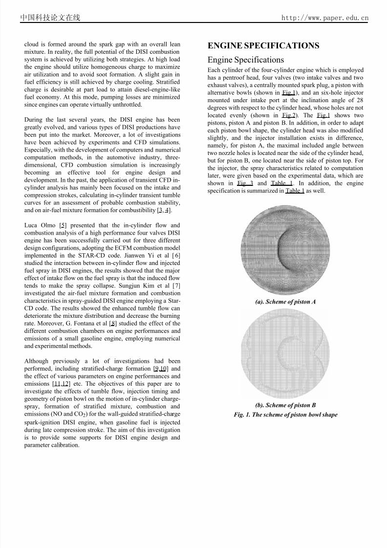
Engine SpecificationsEach cylinder of the four-cylinder engine which is employed
has a pentroof head, four valves (two intake valves and two
exhaust valves), a centrally mounted spark plug, a piston with
alternative bowls (shown in Fig.1), and an six-hole injector
mounted under intake port at the inclination angle of 28
degrees with respect to the cylinder head, whose holes are not
located evenly (shown in Fig.2). The Fig.1 shows two
pistons, piston A and piston B. In addition, in order to adap
each piston bowl shape, the cylinder head was also modified
slightly, and the injector installation exists in difference
namely, for piston A, the maximal included angle between
two nozzle holes is located near the side of the cylinder head
but for piston B, one located near the side of piston top. Fo
the injector, the spray characteristics related to computation
later, were given based on the experimental data, which are
shown in Fig 3 and Table 1. In addition, the engine
specification is summarized in Table 1 as well.
(a). Scheme of piston A
(b). Scheme of piston B
Fig. 1. The scheme of piston bowl shape
中国科技论文在线 http://www.paper.edu.c

7/17/2019 DISI Wall Guided Compression Ignition
http://slidepdf.com/reader/full/disi-wall-guided-compression-ignition 3/16
Fig. 2. The scheme of nozzle holes' distribution
Fig.3. the scheme of spray event in ambient conditions
Table 1. Engine specification and injector parameters
Note: 0 Degree Crank Angle is assigned in TDC intake
stroke
BASIC THEORY AND MODEL
The CFD calculations were performed with AVL Fire codes
The codes solve ensemble-averaged equations for
momentum, energy, species concentration and mass. The
calculations start from the time of intake valve close (IVC
220°CA ATDC) to the time of exhaust valve open (EVO
510°CA ATDC), calculating step lengths are 0.2°CA during
fuel injection and combustion, others are 0.5°CA. During the
whole process, the flow motion event was computed using
the turbulence model, the spray and combustion events
were performed using Discrete Droplet Model (DDM) and
Extended Coherent Flame Model (ECFM). In additionequations of energy, motion and mass were solved using
Upwind Scheme, Central Differencing Scheme and
MINMOD Relaxed Scheme [13,14,16], respectively. The
theories associated with the models were to be simply
introduced below, for details, referring to the literatures
[13,14,15,16].
MeshIn the study, the unstructured grids were adopted, while the
piston was modeled by the dynamic mesh models. The entire
process simulating piston movement was achieved by the
dynamic grids, which were completed using FAME Meshing
(FM) and FAME Engine Plus (FEP) tools. Both of models, a
most, were meshed up to 300,000 grids, including refining
parts. Specific grid models are given in Fig.4 and Fig.5.
中国科技论文在线 http://www.paper.edu.c

7/17/2019 DISI Wall Guided Compression Ignition
http://slidepdf.com/reader/full/disi-wall-guided-compression-ignition 4/16
Fig.4. The scheme of piston A
Fig.5. The scheme of piston B
Initial Conditions and Boundary Conditions
SettingThe initial conditions and boundary conditions are provided
resulting from computational values of GT-Power code, and
some referred experimental values. Table.2 shows essential
values of initial and boundary conditions.
Table.2. Initial Conditions and Boundary Conditions
Setting
Note:* Tumble flow ratio is defined as tumble flow
velocity divided by engine revolved velocity; Ignition
duration is 0.0003 seconds, equaling to 3.6°CA at the
speed of 2000 r/min.
Turbulent flow modelThe k-ε model is used as turbulence model. Here, the k
equation [13, 15] and ε equation [13, 15] are expressed
respectively, as follows:
(1)
Where, is the turbulent kinetic energy, is the tensor o
strain rate associated to fluctuating flow; is the tensor o
strain rate associated to mean flow; is kinematic viscosity
coefficient.
(2)
Where, is the density, is the dissipation rate, is the
Prandtl number of , is the effective viscosity
coefficient, , are the constant, is the turbulen
kinetic energy production term.
Combustion modelThe Extended Coherent Flame Model (ECFM) [13, 15] has
been mainly developed in order to describe combustion in
DISI engines. This model is fully coupled to the spray model
and enables stratified combustion modeling including EGR
effects and NO formation. The model relies on a conditiona
unburnt/burnt description of the thermochemical properties of
the gas. The ECFM contains all the features of the standard
CFM and the improvements of the MCFM. Differences to the
other coherent flame models are described in the reference
[13, 15].
For turbulent combustion phenomena, the ECFM model leads
to the calculation of the mean fuel reaction rate. Hence, this
model uses a 2-step chemistry mechanism [13] for the fue
conversion like:
(3)
(4)
中国科技论文在线 http://www.paper.edu.c
7/17/2019 DISI Wall Guided Compression Ignition
http://slidepdf.com/reader/full/disi-wall-guided-compression-ignition 5/16
whereafter, some basic equations are introduced below.
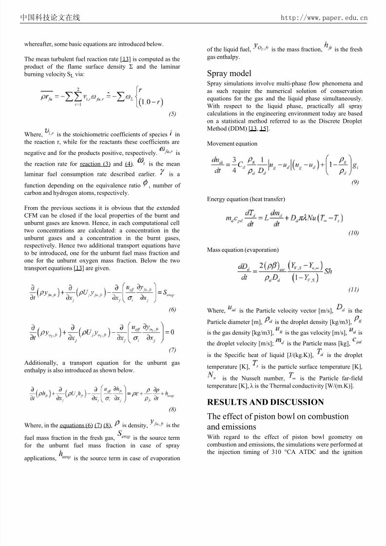
The mean turbulent fuel reaction rate [13] is computed as the
product of the flame surface density Σ and the laminar
burning velocity SL via:
(5)
Where, is the stoichiometric coefficients of species in
the reaction r, while for the reactants these coefficients are
negative and for the products positive, respectively. is
the reaction rate for reaction (3) and (4). is the mean
laminar fuel consumption rate described earlier. is a
function depending on the equivalence ratio , number of
carbon and hydrogen atoms, respectively.
From the previous sections it is obvious that the extended
CFM can be closed if the local properties of the burnt and
unburnt gases are known. Hence, in each computational cell
two concentrations are calculated: a concentration in the
unburnt gases and a concentration in the burnt gases,
respectively. Hence two additional transport equations have
to be introduced, one for the unburnt fuel mass fraction and
one for the unburnt oxygen mass fraction. Below the two
transport equations [13] are given.
(6)
(7)
Additionally, a transport equation for the unburnt gas
enthalpy is also introduced as shown below.
(8)
Where, in the equations (6) (7) (8), is density, is the
fuel mass fraction in the fresh gas, is the source term
for the unburnt fuel mass fraction in case of spray
applications, is the source term in case of evaporation
of the liquid fuel, is the mass fraction, is the fresh
gas enthalpy.
Spray modelSpray simulations involve multi-phase flow phenomena and
as such require the numerical solution of conservation
equations for the gas and the liquid phase simultaneously
With respect to the liquid phase, practically all spray
calculations in the engineering environment today are based
on a statistical method referred to as the Discrete Droplet
Method (DDM) [13, 15].
Movement equation
(9)
Energy equation (heat transfer)
(10)
Mass equation (evaporation)
(11)
Where, is the Particle velocity vector [m/s], is the
Particle diameter [m], is the droplet density [kg/m3],
is the gas density [kg/m3], is the gas velocity [m/s], is
the droplet velocity [m/s]; is the Particle mass [kg],
is the Specific heat of liquid [J/(kg.K)], is the drople
temperature [K], is the particle surface temperature [K]
is the Nusselt number, is the Particle far-field
temperature [K], λ is the Thermal conductivity [W/(m.K)].
RESULTS AND DISCUSSION
The effect of piston bowl on combustion
and emissionsWith regard to the effect of piston bowl geometry on
combustion and emissions, the simulations were performed a
the injection timing of 310 °CA ATDC and the ignition
中国科技论文在线 http://www.paper.edu.c

7/17/2019 DISI Wall Guided Compression Ignition
http://slidepdf.com/reader/full/disi-wall-guided-compression-ignition 6/16
timing of 345 °CA ATDC, by varying tumble flow ratio for
two different piston bowl shapes.
Interaction between flow and spray
Fig.6 shows the interaction between charge flow and spray
inside combustion chamber for the stratified-charge direct-
injection gasoline engine. When the spray is induced into
cylinder, in-cylinder single vortex is transformed two ones
around the spray for each piston. Before the spray impinges
the piston bowl surface, many droplets change their
directions and move perpendicularly to the spray axis toward
the top of the combustion chamber. The reason for this
drastic change in the flow direction is the strong influence of
the in-cylinder airflow on the smaller droplets [17]. Then, at
the end of injection, the spray head direction is changed along
piston bowl surface for each piston, due to the effect of piston
bowl profile and tumble flow. As far as two pistons are
concerned, the piston B seems to be more suitable for mixture
stratification at the injection timing of 310 °CA ATDC.
<figure 6 here>
In addition, different tumble intensity causes the spray
velocity difference along the piston bowl contour for two
piston bowls. Moreover, there exists a distinct spray plume
structure inside combustion chamber with two different
pistons, mainly resulting from asymmetric distribution of
holes, and as mentioned before, the nozzle holes are located
differently around the axis of the hole where the injector is
installed.
In-cylinder mixture strength
The mixture formation has a significant impact on
combustion and emissions. Therefore, it is quite important to
study in-cylinder fuel-air distribution. The references [3, 4, 5,
10] presented the results of mixture formation. In those
investigations, the spatial distribution and temporal history of
mixture formation were studied. Besides, mixture strength is
designated as equivalence ratio.
For an engine operation in the stratified charge mode, the
spatial distribution and temporal development of the mixture
strength are shown in Fig. 7. At the end of fuel injection (324
°CA ATDC), the thickest mixture exists inside the down-
right side of combustion chamber, due mainly to theincomplete evaporated spray droplets. As the piston moves
up, the thick mixture also reaches near the spark plug,
resulting mainly from the interaction among spay, piston
bowl profile and tumble flow. Regardless of piston A or
piston B, the tumble flow plays an important role in mixture
formation. In addition, Fig.7 also shows that fuel-air mixture
is stratified by two types of piston bowls, due to the
interaction between spray and piston top. However, compared
to the piston A, the piston B is much fitter to stratified-charge
mixture formation, when fuel is injected inside the cylinder at
the time of 310 °CA ATDC. At the same time, as shown in
Fig.8(d), it is also acquired, for the piston B under tumble
flow ratio (TR) of 1, that the appropriate mixture around the
spark gap is formed, resulting mainly from the effect o
intensified tumble flow.
<figure 7 here>
Combustion Characteristics
Fig.8 shows the spatial distribution and temporal history of
in-cylinder temperature throughout the combustion chamber
Firstly, it shows that the spatial distribution of in-cylinder
temperature for the piston bowl B is superior to that of the
piston bowl A, which is the result of favorable stratified
mixture formation for the piston bowl B. Furthermore, it can
be also found that tumble intensity has a strong influence on
the in-cylinder temperature. Lastly, it implies that the
stratified mixture leads to in-cylinder temperature
stratification throughout the combustion chamber, especially
for the piston bowl B, it is more obvious as the result ofappropriate stratified mixture and stable combustion.
<figure 8 here>
Fig.9. Effect of piston bowl on combustion
中国科技论文在线 http://www.paper.edu.c

7/17/2019 DISI Wall Guided Compression Ignition
http://slidepdf.com/reader/full/disi-wall-guided-compression-ignition 7/16
Fig.10. Effect of piston bowl on mean in-cylinder
temperature at various tumble flow ratios
Fig.9 shows the comparisons of mean in-cylinder pressure,
rate of heat release and accumulated heat release between the
piston A and the piston B under different tumble flow ratio
(TR). It can be found that the mean pressure is some slightly
different between the piston A and the piston B. However, the
strong tumble flow intensity leads to mean pressure increase
due to stronger tumble flow improving mixture formation and
accelerating combustion process, but tumble flow is too
strong to form proper air-fuel mixture in the position of spark
plug, so tumble intensity is enhanced properly.
Furthermore, as far as the accumulated heat release in Fig.9concerned, compared to the piston B, the piston A is sensitive
to tumble flow intensity, due to piston A shape resulting in
the worse air-fuel mixture with the TR of 0.5. Hence it is
clearly effective for the piston A with the TR of 1.
For the piston B, the rate of heat release and the accumulated
heat release are higher than that of the piston A, regardless of
tumble intensity. Moreover, the strong tumble flow causes
them to rise greatly. The main reasons are that the fast-
burning period becomes shorter, and that the location of area
center in the curve of heat release rate is closer to the top
dead center (TDC) and the combustion process is remarkably
improved [18].
Fig.10 shows the effect of piston bowl shape on mean in-
cylinder temperature under different tumble flow ratio (TR).
It shows that the mean in-cylinder temperature for the piston
B is higher than that of the piston A, as the result that, when
compared to the piston A, the spatial distribution of air-fuel
mixtures for the piston B is better throughout the whole
combustion chamber, and acquiring a stable, stratified-charge
combustion. In addition, the tumble flow motion not only
influences the stratification mixture formation, but also
affects flame kernel formation and flame propagation, hence
with the tumble flow ratio of 1, in-cylinder combustion
process is satisfying, due mainly to appropriate tumble flow
intensity improving mixture formation and accelerating
robust combustion.
For the piston A, when the tumble flow ratio is the value of
0.5, there exist two distinct peak values of mean in-cylindertemperature. The second peak value arises resulting mainly
from the strong post-combustion.
Emissions
Fig.11 shows the effect of piston bowl types on CO2
emissions at various tumble flow ratios. Regardless of tumble
flow ratio, for the piston B, CO2 emissions, are generated
more than that of the piston A, due to mainly appropriate
stratified-charge mixture formation and relatively complete
combustion. On the other hand, regardless of piston bow
shape, the stronger tumble flow promotes more appropriate
stratified-charge mixture formation and more adequatecombustion, leading to more CO2 emissions generation.
Combined with the accumulated heat release in Fig.9, it is
higher for the piston A than that of the piston bowl B with the
TR of 1. However, it shows that carbon dioxide is less for the
piston A, as its piston bowl shape resulting in different air
fuel mixture distribution. Although it is clearly effective for
air-fuel mixture formation of the piston bowl A to enhance
tumble flow, but compared to the piston B, air-fuel mixture
stratification is worse for the piston A, so a lot of carbon
monoxide emission is generated. Besides, the unburn
hydrocarbon is more for the piston B due to better air-fuel
mixture stratification resulting in quenching in the position
far from the spark plug.
Fig.12 shows the effect of piston bowl types on NO
emissions formation at various tumble flow ratios. Generally
speaking, the NOx formation strongly depends on the
combustion temperature and combustion duration at high
temperature. Likewise, for piston B, NO emissions are
generated more than that of the piston A, regardless of tumble
flow ratio, due to mainly the piston B fitting more to
stratified-charge mixture formation and robust combustion
On the other hand, for each piston bowl, the stronger tumble
flow is formed, the more amount of NO emissions isgenerated. Moreover, for piston A at tumble flow ratio of 0.5
the amount of NO emissions equals nearly to zero, as the
result of lower combustion temperature.
中国科技论文在线 http://www.paper.edu.c

7/17/2019 DISI Wall Guided Compression Ignition
http://slidepdf.com/reader/full/disi-wall-guided-compression-ignition 8/16
Fig.11. Effect of piston bowl on CO2 emissions
Fig.12. Effect of piston bowl on NO emissions
The effect of tumble flow on combustion
and emissions for piston BIt is known that in-cylinder airflow fields have the prominent
influence on combustion and emission characteristics.
Therefore, the section presents the effect of the tumbleintensity on mean in-cylinder pressure, the rate of heat release
and the accumulated heat release at injection timing at 278
°CA ATDC for the piston B.
Fig.13 shows the effect of different tumble flow ratios on
combustion characteristics, including in-cylinder mean
pressure, rate of heat release and accumulated heat release.
The strong tumble flow contributes to stratified-charge
formation at early stage of compression stroke and to
turbulence intensity near TDC during compression stroke.
However, as tumble flow ratio increases, heat release rate is
enhanced, and the phase is advanced, as the result that the
stronger tumble flow causes beneficial air-fuel mixture
around the spark gap, and better stratified-charge mixture
throughout combustion chamber. In addition, accumulated
heat release also increases, but there are slightly distinct
variations for mean in-cylinder pressure.
Fig.14 shows the effect of different tumble flow ratios on
mean in-cylinder temperature. It shows that mean in-cylinder
temperature dramatically increases as tumble flow is
enhanced. In addition, the inflexion of mean temperature is
advanced as well as it is possibly attributed to tumble flow
improving in-cylinder mixture distribution and enhancing
turbulence flow near top dead center (TDC). Finally, all
accelerate the rate of heat release rate.
Fig. 13. Effect of tumble flow on combustion
中国科技论文在线 http://www.paper.edu.c

7/17/2019 DISI Wall Guided Compression Ignition
http://slidepdf.com/reader/full/disi-wall-guided-compression-ignition 9/16
Fig.14. Effect of tumble flow on mean in-cylinder
temperature
Fig. 15. Effect of tumble flow ratio on carbon dioxide
Fig. 16. Effect of tumble flow ratio on nitrous oxide
The CO2 and NO emissions are given in Fig.15 and Fig.16
respectively. In Fig.15, it can be found that, increasing
tumble flow ratio, the starting of combustion is slightly
advanced, and the amount of CO2 rises dramatically as well
due mainly to appropriate stratified-charge mixture caused by
tumble flow.
The NO formation depends strongly on in-cylinder
temperature and combustion duration at high temperature
The results shown in Fig.16 keep in accordance with the
principle. The stronger tumble flow promotes the bette
stratified-charge formation, leading to a stable combustion
generation.
The effect of injection timing on
combustion and in-cylinder emissions for
piston bowl B at TR=0.5
Combustion
The start of injection (SOI) is an important parameter because
it affects the combustion characteristics and exhaus
emissions of the engine. To achieve the higher degree o
stratification of the air-fuel mixture, the accurate control o
the quantity and timing of fuel injection is necessary
Therefore, it is important to investigate the effect of injection
timing on combustion and emission characteristics later. Inthe investigation, regarding to the piston B, combustion
characteristics and emissions are given afterwards.
中国科技论文在线 http://www.paper.edu.c

7/17/2019 DISI Wall Guided Compression Ignition
http://slidepdf.com/reader/full/disi-wall-guided-compression-ignition 10/16
Fig.17. Effect of injection timing on combustion
Fig.18. Effect of injection timing on mean temperature
Fig.17 shows the mean in-cylinder pressure, heat release rate
and accumulated heat release characteristics. As injection
timing is retarded, in-cylinder combustion characteristics
don't vary monotonously, in other words, there exists an
optimization value of injection timing. In the calculatingmodel, the injection timing of 298°CA ATDC is better,
relative to that of 278 °CA ATDC and 310°CA ATDC.
Considering the fact that stratified combustion dramatically
increases the combustion pressure, it can be concluded that
the proper delay of injection timing can lead to the desired
stratification of the mixture.
Fig.18 shows the effect of injection timing on mean in-
cylinder temperature. Considering the fact that stratified
combustion dramatically improves combustion process at part
load, it can be concluded that the delay of injection timing
can lead to the desired stratification of the mixture. Hence, it
can be found that, the appropriate delay of injection timing
causes mean in-cylinder temperature to rise.
Emissions
In this part of the study, the exhaust emissions such as CO2
NO, were compared for the three injection timings at the
different crank angles. The relationships between each
emission and injection timing were separately discussed
Some observations between the emissions were also given in
this paragraph.
Fig.19. Effect of injection timing on carbon dioxide
Fig.20. Effect of injection timing on nitrous oxide
CO2 and NO Emissions are given in Fig.19 and Fig.20
respectively. For the injection timing of 298°CA ATDC, it is
suitable to the piston bowl shape at ignition timing of
345°CA ATDC. Therefore, CO2 emissions generate
relatively high, due to adequate combustion.
中国科技论文在线 http://www.paper.edu.c

7/17/2019 DISI Wall Guided Compression Ignition
http://slidepdf.com/reader/full/disi-wall-guided-compression-ignition 11/16
In general, at the temperatures over 1800 K, NO generation
rate increases rapidly with increasing combustion
temperature. Therefore, the peak combustion temperature
must be kept below 1800 K to prevent the rapid NO
formation. At the injection timing of 298 °CA ATDC, NO
emissions generate relatively high, as the result of adequate
combustion leading to a higher temperature and combustion
period at high temperature. At the injection timing of 278°CAATDC, because the stratified-charge mixture is formed
unsuitably, especially at the time of ignition, combustion
temperature can't reach the level of lots of NO generated,
resulted the NO emissions at the level of nearly to zero.
In addition, other literatures [19] present some information,
which fuel stratification within the cylinder produces local
equivalence ratio different from the global equivalence ratio.
Therefore, the local fuel enrichment will result in relatively
high local temperatures. Thus, the high local temperatures
provide the energy required to form NO at a rapid rate. Fuel
stratification can be achieved by retarded SOI timing in a
direct injection system.
CONCLUSIONS
The simulating results of this study were summarized as
follows:
The piston bowl shape is a key parameter, which can promote
the stratified-charge formation and combustion process in the
SCDI gasoline engine. In this case, compared to the piston A,
the piston B is more suitable for the stratified combustion at
the injection timing of 310°CA ATDC, subsequently, the
ignition timing of 345°CA ATDC.
In general, tumble flow affects the degree of mixture
stratification, flame kernel formation and flame diffusion.
The stronger tumble flow exists in the combustion chamber,
the better stratified-charge mixture is formed, and however,
tumble flow is excessively strong resulting in blowing out the
flame kernel, misfiring and quenching and so on.
To achieve high degree of stratification of the charge, the
accurate control of injection timing is necessary. Advancing
or retarding injection timing excessively, deteriorate mixture
formation, therefore, there is an optimization value. For the
investigated piston B, the injection timing of 298°CA ATDCis more appropriate at ignition timing of 345°CA ATDC with
the tumble flow ratio of 0.5, compared to that of 278°CA
ATDC and 310°CA ATDC.
ACKNOWLEDGMENT
The authors would like to appreciate the funding of this study
from Geely and Tongji Automotive Research Institute.
CONTACT
Dr Liguang Li, Prof.
School of Automotive Studies
Tongji University, Shanghai, 201804, P.R. China.
Tel: +86 21 69583817
Fax: +86 21 69589978
Qianwang Fan
PhD Candidate
REFERENCES
1. Zhao, F., “Automotive Gasoline Direct Injection
Engines,” SAE International, Warrendale, PA, ISBN
978-0-7680-0882-1, 2002.
2. Rotondi Rossella, Bella Gino. Gasoline direct injection
spray simulation. International Journal of Thermal Sciences
45 (2006) 168-179.
3. Schänzlin, K., Koch, T., Tzannis, A.P., and Boulouchos,
K., “Characterization of Mixture Formation in a Direct
Injected Spark Ignition Engine”, SAE Technical Paper
2001-01-1909, 2001.
4. Hélie, J., Duclos, J.-M., Baritaud, T., Poinsot, T. et al.,
“Influence of Mixture Fluctuations on Combustion in Direct
Injection Spark Ignition Engines Simulations,” SAE
Technical Paper 2001-01-1226, 2001.
5. Olmo, L. and Thornton, J., “CFD Analysis of Mixture
Formation and Combustion Process for High Performance DI
Gasoline Engine,” SAE Technical Paper 2005-01-0214,2005.
6. Yi, J., Han, Z., Yang, J., Anderson, R. et al., “Modeling of
the Interaction of Intake Flow and Fuel Spray in DISI
Engines,” SAE Technical Paper 2000-01-0656, 2000.
7. Kim, S.-J., Kim, Y.-N., and Lee, J.-H., “Analysis of the
In-Cylinder Flow, Mixture Formation and Combustion
Processes in a Spray-Guided DISI Engines,” SAE Technical
Paper 2008-01-0142, 2008.
8. Fontana, G., Galloni, E., Palmaccio, R., and Torella, E.,
“Numerical and Experimental Analysis of Different
Combustion Chambers for a Small Spark-Ignition Engine,”SAE Technical Paper 2004-01-1998, 2004.
9. Ohm, I.Y. and Cho, Y.S., “Fuel Stratification Process in
the Cylinder of an Axially Stratified Engine,” SAE Technical
Paper 2000-01-2842, 2000.
10. Kano, M., Saito, K., Basaki, M., Matsushita, S. et al.,
“Analysis of Mixture Formation of Direct Injection Gasoline
Engine,” SAE Paper 980157, 1998.
中国科技论文在线 http://www.paper.edu.c

7/17/2019 DISI Wall Guided Compression Ignition
http://slidepdf.com/reader/full/disi-wall-guided-compression-ignition 12/16
11. Kaiser, E. W., Siegl, W.O., Brehob, D.D., and
Haghgooie, M.,“Engine-Out Emissions from a Direct-
Injection Spark-Ignition (DISI) Engine,” SAE Technical
Paper 1999-01-1529, 1999.
12. Muñoz, R.H., Han, Z., VanDerWege, B., and Yi, J.,
“Effect of Compression Ratio on Stratified-Charge Direct-
Injection Gasoline Combustion,” SAE Technical Paper
2005-01-0100, 2005.
13. AVL Fire_2008_CFD User Manual.
14. Anderson John D.. Computational Fluid Dynamics.
15. Xie Maozhao. Computational Combustion of Internal
Combustion Engine. Dalian University of Science and
Technology press, China, 2005.
16. Wu Deming and Hao Ye. Practical Computational Fluid
Dynamics Fundamentals. Haerbin Engineering Universuty
press, China, 2006.
17. Hentschel Werner. Optical diagnostics for combustion
process development direct injection gasoline engines.
Proceedings of the Combustion Institute 28:1119-1135, 2005.
18. Wei Li, Ying Wang et al. Study on improvement of fuel
economy and reduction in emissions for stoichiometric
gasoline engines. Applied Thermal Engineering 27
2919-2923, 2007.
19. Canakci Mustafa. An experimental study for the effects
of boost pressure on the performance and exhaust emissions
of a DI-HCCI gasoline engine. Fuel 87:1503-1514,2008.
ABBREVIATION AND DEFINITION
ATDC
After Top Dead Center
BSFC
Brake Specific Fuel Consumption
BC
Boundary Condition
CA
Crank Angle
CFD
Computational Fluid Dynamics
CO2
Carbon dioxide
DISI
Direct Injection Spark Ignition
DI
Direct Injection
ECFM
Extended Coherent Flame Model
FM
FAME Meshing
FEP
FAME Meshing Plus
DISI
Direct Injection Spark Ignition
NO
Nitrogen oxide
PFI
Port Fuel Injection
SCDI
Stratified Charge Direct Injection
SOI
Start of Injection
TR
Tumble flow ratio
中国科技论文在线 http://www.paper.edu.c

7/17/2019 DISI Wall Guided Compression Ignition
http://slidepdf.com/reader/full/disi-wall-guided-compression-ignition 13/16
Fig.6. Interaction between charge-flow and spray
中国科技论文在线 http://www.paper.edu.c

7/17/2019 DISI Wall Guided Compression Ignition
http://slidepdf.com/reader/full/disi-wall-guided-compression-ignition 14/16
Fig.7. Mixture strength on different sections through the combustion chamber at various crank angles (the symbol “•” denotes
spark plug position.)
中国科技论文在线 http://www.paper.edu.c

7/17/2019 DISI Wall Guided Compression Ignition
http://slidepdf.com/reader/full/disi-wall-guided-compression-ignition 15/16
Fig.8. Spatial distribution and temporal history of in-cylinder temperature
中国科技论文在线 http://www.paper.edu.c

7/17/2019 DISI Wall Guided Compression Ignition
http://slidepdf.com/reader/full/disi-wall-guided-compression-ignition 16/16
The Engineering Meetings Board has approved this paper for publication. It has
successfully completed SAE's peer review process under the supervision of the session
organizer. This process requires a minimum of three (3) reviews by industry experts.
All rights reserved. No part of this publication may be reproduced, stored in a
retrieval system, or transmitted, in any form or by any means, electronic, mechanical,
photocopying, recording, or otherwise, without the prior written permission of SAE.
ISSN 0148-7191
doi:10.4271/2010-01-0595
Positions and opinions advanced in this paper are those of the author(s) and not
necessarily those of SAE. The author is solely responsible for the content of the paper.
SAE Customer Service:Tel: 877-606-7323 (inside USA and Canada)
Tel: 724-776-4970 (outside USA)
Fax: 724-776-0790
Email: [email protected]
SAE Web Address: http://www.sae.org
Printed in USA
中国科技论文在线 http://www.paper.edu.c


![Homogeneous Charge Compression Ignition (HCCI ... emissions in a highly competitive era [1, 2]. Compression Ignition (CI) and Spark Ignition (SI) combustion are two primary technologies](https://img.dokumen.tips/doc/110x75/5aca15977f8b9a5d718deb8b/homogeneous-charge-compression-ignition-hcci-emissions-in-a-highly-competitive.jpg)