Embed Size (px)
Citation preview

Renaissance™ SystemsRevive wells at a fraction of the cost of workovers with Weatherford’s unique safety-valve innovations
Discover premium performance.
Renaissance™ Systems
Troubled wells can be a problem of the past with the innovation of Weatherford’s Renaissance safety-valve system. Damaged nipple bores, damaged control lines or production-enhancing chemical requirements—Weatherford has the solutions for your well’s renewal. For more details on the Renaissance system, contact your local Weatherford representative today at [email protected], or visit weatherford.com.
Discover premium performance.
weatherford.comWeatherford products and services are subject to the Company’s standard terms and conditions, available on request or at weatherford.com. For more information contact an authorized Weatherford representative. Unless noted otherwise, trademarks and service marks herein are the property of Weatherford and may be registered in the United States and/or other countries. Weatherford products named herein may be protected by one or more U.S. and/or foreign patents. For more information, contact [email protected]. Specifications are subject to change without notice. Weatherford sells its products and services in accordance with the terms and conditions set forth in the applicable contract between Weatherford and the client.
© 2009–2011 Weatherford. All rights reserved. 5977.02

2 © 2009–2011 Weatherford. All rights reserved.

Renaissance™ Systems
The intellectual transformation known as the Renaissance began in the 14th century and sparked a revival of learning in arts and sciences. It expanded horizons and built a bridge to the modern era.
Weatherford’s Renaissance system of safety valves offers a revival for troubled wells—expanding horizons for a productive well life and building a bridge for more profitable reservoir management.
3© 2009–2011 Weatherford. All rights reserved.

Renaissance™ Systems
Revolutionary approach to wellbore revival
The Renaissance safety-valve system originated from Weatherford’s Optimax™ valve technology—proven to be the toughest valves in the industry. The Renaissance system combines recent advances in valve technology with patent-pending new technology, providing an integrated, single-source approach to renew wells suffering from four types of safety-valve-related problems:
Damaged control linesControl lines for subsurface safety valves (SSSVs) could leak, break or plug up, closing the valve and shutting in production. In the past, the only way to remedy this situation in offshore workovers was to pull the tubing, an expensive operation. The Renaissance WDCL (Weatherford damaged control line) safety valve can restore safe operation and bring the well back on line without a workover—significantly reducing costs. The Renaissance WDCL also can be used to retrofit safety valves on wells that currently do not have safety valves—thus meeting new environmental standards at a significantly reduced cost.
Damage to safety-valve landing nipples or sealboresInstalling a new wireline SSSV can be impossible if the sealbore of the safety-valve landing nipple has been gouged or grooved, preventing the new valve from sealing. Today, the Renaissance WDB (Weatherford damaged bore) safety valve provides a simple fix without a workover.
Application of production-enhancing chemicalsProduction-enhancing chemicals can solve problems, such as liquid loading, salt and mineral buildup, and corrosion. However, until now the only way to get chemicals into a well with a surface-controlled safety valve was to pull and replace existing tubing. The Renaissance WCS (Weatherford capillary system) safety valve offers a retrofit solution that provides a capillary-injection system and a surface-controlled safety valve without a workover.
Combine plunger-lift technology with a wireline-retrievable safety valve When foamers and surfactants are ineffective, the SafetyLift™ system offers efficient and commonly used plunger-lift technology coupled with a wireline-retrievable safety valve. Energy generated by the well is used to lift the fluids and mitigate liquid-loading issues, making the SafetyLift system an ideal solution for offshore applications.
© 2009–2011 Weatherford. All rights reserved.4

Renaissance™ Systems
5© 2009–2011 Weatherford. All rights reserved.
The Renaissance system of safety valves is engineered for optimal, reliable performance, providing a custom-fit solution for each well. In addition, each valve offers the benefits of simplicity, safety, cost reduction and overall extended reservoir recovery.
Retrofitting for reservoir recovery
Eliminates workoversComponents of the Renaissance system work together faultlessly to provide customized solutions to reduce the need for costly workovers. Depending on the location, the cost of a workover can exceed US$10 million.
Extends reservoir profitability by extending recoverable lifeThe Renaissance system: • Solves well safety-valve problems that could otherwise force the well
to be plugged and abandoned. Even better, the Renaissance system’s retrofit solutions can often be installed in a day.
• Installs SSSVs easily in wells that do not have SSSVs, thus meeting environmental requirements and enabling old wells to stay in production.
• Makes it possible to install a capillary chemical-injection line in a well with a safety valve without pulling the tubing. Gas wells in particular can be unloaded and kept producing by foamers injected downhole.
• Can add safety shut-in systems without a workover operation to wells where government regulations now require safety valves be installed. A situation that historically meant that wells would either be pulled or abandoned.
• Allows the combination of plunger lift and safety valve.
Ensures optimal productionWhen compared to standard wireline valves with concentric pistons, the new technology used by the Renaissance system has a larger standard flow area—resulting in a minimal reduction in flow area compared to standard wireline valves.

Renaissance™ Systems
Simple installation and retrievalRenaissance systems can be installed by standard wireline and capillary string units (WDB requires wireline only). Weatherford
offers a small-footprint, skid-mounted, cap-string/slickline unit engineered for 1/4- and 3/8-in. strings, keeping installation
fast and inexpensive. The unit’s design allows for small platform cranes to make required lifts without the need
for additional crane capacity. Weatherford is the only service company that has the capability to use
the smaller lifting capacity—differentiating us from all others.
Available from a single sourceThe Renaissance system is fully integrated, and Weatherford offers everything related to the system—wellheads, capillary systems, safety systems, wireline and chemicals—parts and installation. We are the only company that offers all these comprehensive services—a true single-source provider.
Withstands corrosive environmentsRenaissance valves are based on the Weatherford Optimax™ series of valves that have the best reliability record in the industry. Features of Optimax and Renaissance valves include:
• Flapper soft-seal provides excellent heat and chemical resistance for a reliable low-pressure seal.
• Valves use field-proven, metal-to-metal, through-the-flapper equalizing technology for ultimate durability and reliability to protect persons, property and the environment.
• The temperature rating of the valve is 300°F (149°C) and is rated to 5,000 psi (34 MPa) with a burst pressure of 7,500 psi (52 MPa).
6 © 2009–2011 Weatherford. All rights reserved.

Renaissance™ Systems
7© 2009–2011 Weatherford. All rights reserved.
Renaissance WDCL valve
WDCL components.
Renaissance control line hanger The RQXC-CLH is used to hang the new capillary control line from the modified wellhead. The RQXC-CLH can be landed in tubing hangers with premium wireline profiles, or configured to land in type-H threaded backpressure valve profiles. The RQXC-CLH is run and landed with standard wireline running tools. The RQXC-CLH has a similar bypass area as the new WDCL safety valve.
Renaissance capillary control lineThis line runs down the center of the tubing to a pod on the Renaissance WDCL valve. The pod redirects the flow of hydraulic fluid to a rod-and-piston mechanism that activates the safety valve. The capillary sizes are 1/4 or 3/8 in. for all standard metallurgies and wall thicknesses.
Modified wellheadThe wellhead must be modified to provide the correct profile for the capillary hanger and to gain access for the new capillary control line, which goes down inside the tubing. The simplest approach is to add a spool that already has the valve connection. Weatherford can customize the penetration when well bay and flowline constraints dictate. Weatherford has developed a new wellhead penetration REN GATE™ system that is installed in situ without changing the original wellhead geometry.
In the past, replacing a leaking or blocked safety-valve control line required a workover. The Renaissance WDCL system—a surface-controlled safety shut-in system—now makes it possible to replace both control line and safety valve in a simple retrofit procedure. The sealbores and landing nipple profile must be undamaged.

Renaissance™ Systems
8 © 2009–2011 Weatherford. All rights reserved.
Renaissance WDCL pod
This special WDCL device contains the male end of the wet-connect, and it reroutes the flow of hydraulic fluid from the centralized capillary sting to a flow path within the outer perimeter of the valve.
Renaissance stinger
At the end of the capillary line is a weighted and centralized stinger with the female end of a unique Weatherford wet-connect that will join the capillary to the mating connection in the pod attached to the valve. The wet-connect is unique: it can be mated and unmated, so the capillary can be removed if necessary, and it is hydraulically locked in place when pressure is applied to the capillary string.
Design of the wet-connect eliminates the complications and additional leak paths that a hydraulically operated latch
would create. The stinger also features dual-back check valves that prevent backflow through the capillary
line, a key safety feature.
Renaissance WDCL SSSV
Based on the advanced technology of Weatherford’s Optimax™ safety valves, the new Renaissance SSSV is engineered to land in the safety-valve landing nipple from a previous wireline valve, or to land inside an existing tubing-mounted safety valve. This design, combined with the rod-piston actuated flapper valve, maintains 80 percent of the maximum flow area of conventional wireline retrievable valves that are currently on the market.

Renaissance™ Systems
Using the REN GATE™ wellhead modification, the Renaissance WDCL can usually be installed in a day.
Installation includes:
WDCL running sequence
9© 2009–2011 Weatherford. All rights reserved.
• Retrieve existing wireline safety valve or lock open existing tubing valve (no communication needed)
• Block existing control line• Install required barriers in tubing• Modify to REN GATE wellhead• Retrieve barriers• Run WDCL safety valve• Run and space out capillary string• Run capillary string with cap-string
hanger• Land cap-string hanger and wet mate• Test WDCL safety valve and bring
well on line

Renaissance™ WDCL Safety Valve System
Weatherford WDCLRenaissance Valve Assembly
Closed Open
Weatherford Wet Mate Assembly.950 Max OD.
� Designed to connect capillary string from surface to Safety Valve
� 20 lb. latch force
� 220 lb. pull to release
� Includes dual barrier for running and pulling in snubbing connections
Weatherford “POD” Assembly
� Directs control line fluid from capillary string to rod piston of Safety Valve
Flapper Seat Assembly
� Standard metal to metal flapper seal with elastomeric soft seat
OpenClosed

Renaissance WDB valve
How it worksThe secret to the WDB is a unique activated packing system:
Renaissance activating pistonsPistons located above and below each set of packing energizes the packing stacks and causes them to expand into the damaged sealbore, forming a pressure-tight seal.
Soft (low-durometer) sealsLow-durometer seals are mounted on the activating pistons to form an initial seal and enable the pistons to energize the packing stacks.
Pressuring up When the control line is pressured up, the low-durometer seals off in the sealbores, compressing the packing into the bore damage and affecting a permanent seal. The low durometer seals maintain the packing set.
Holding pressure The pistons are engineered so that pressure within the tubing and control line will continue to activate them and keep the packing set.
The Renaissance WDB is engineered to seal a replacement safety valve in place when the sealbore or landing nipple has been damaged to a degree that traditional solutions will not work or oversized packing will not seal it. In the past, there were two ways to resolve the problem:
• Pull the tubing and replace it, which is not cost effective; or• Use two retrievable packers to straddle the damaged
sealbores and a ported sub to provide control fluid access to the safety valve, an expensive and complex solution.
Today, the Renaissance WDB valve can do the job for a small fraction of the cost. The WDB
wireline valve has a 95 percent success record in more than 200 wells.
10 © 2009–2011 Weatherford. All rights reserved.
Renaissance™ Systems

To simulate the damaged nipple in actual completions, Weatherford took a 3.813-in. (96.85-mm) nipple and damaged it with the following longitudinal scratches inside:
• One set of four grooves of 0.0059 in. (0.15 mm) deep • One gouge 0.0197 in. (0.50 mm) deep by 0.5118 in. (13 mm) wide• One gouge 0.0256 in. (0.65 mm) deep by 0.5905 in. (15 mm) wide• One gouge 0.0315 in. (0.80 mm) deep by 0.6299 in. (16 mm) wide• One gouge 0.0394 in. (1.00 mm) deep by 0.7087 in. (18 mm) wide
Proof: A Renaissance WDB SSSV Success
Installation of a Renaissance WDB SSSV solved the problem. Even with such severe sealbore damage, the valve held 6,500 psi (44.8 MPa) in the control-line pressure and 7,000 psi (48.3 MPa) (nitrogen) in the tubing.
After running a standard valve inside the damaged nipple, Weatherford could not prevent the hydraulic oil from leaking.
Renaissance™ Systems
11© 2009–2011 Weatherford. All rights reserved.
Renaissance™ Systems
12 © 2009–2011 Weatherford. All rights reserved.
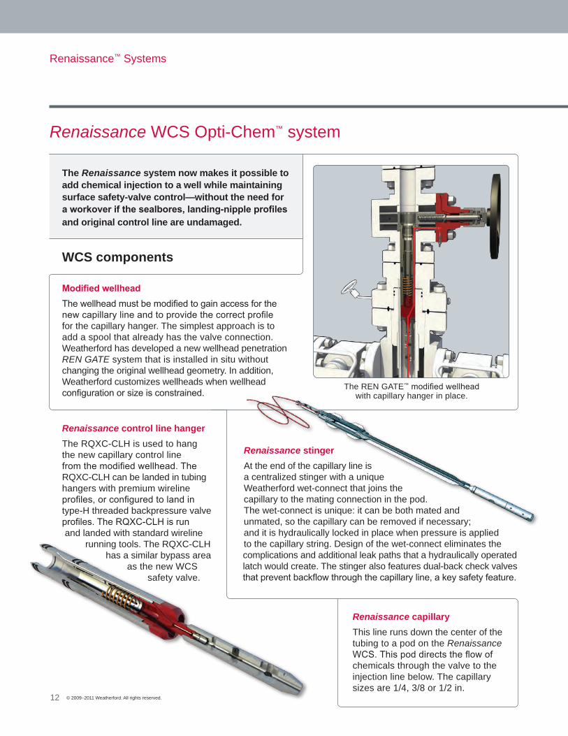
The Renaissance system now makes it possible to add chemical injection to a well while maintaining surface safety-valve control—without the need for a workover if the sealbores, landing-nipple profiles and original control line are undamaged.
Renaissance WCS Opti-Chem™ system
Modified wellheadThe wellhead must be modified to gain access for the new capillary line and to provide the correct profile for the capillary hanger. The simplest approach is to add a spool that already has the valve connection. Weatherford has developed a new wellhead penetration REN GATE system that is installed in situ without changing the original wellhead geometry. In addition, Weatherford customizes wellheads when wellhead configuration or size is constrained.
WCS components
The REN GATE™ modified wellhead with capillary hanger in place.
Renaissance stingerAt the end of the capillary line is a centralized stinger with a unique Weatherford wet-connect that joins the capillary to the mating connection in the pod. The wet-connect is unique: it can be both mated and unmated, so the capillary can be removed if necessary; and it is hydraulically locked in place when pressure is applied to the capillary string. Design of the wet-connect eliminates the complications and additional leak paths that a hydraulically operated latch would create. The stinger also features dual-back check valves that prevent backflow through the capillary line, a key safety feature.
Renaissance control line hangerThe RQXC-CLH is used to hang the new capillary control line from the modified wellhead. The RQXC-CLH can be landed in tubing hangers with premium wireline profiles, or configured to land in type-H threaded backpressure valve profiles. The RQXC-CLH is run and landed with standard wireline
running tools. The RQXC-CLH has a similar bypass area
as the new WCS safety valve.
Renaissance capillaryThis line runs down the center of the tubing to a pod on the Renaissance WCS. This pod directs the flow of chemicals through the valve to the injection line below. The capillary sizes are 1/4, 3/8 or 1/2 in.
Renaissance™ Systems
13© 2009–2011 Weatherford. All rights reserved.
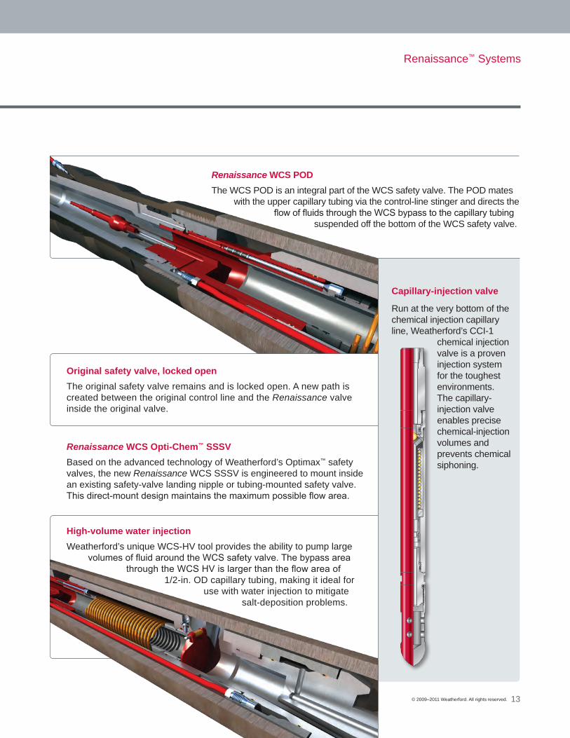
Capillary-injection valve
Run at the very bottom of the chemical injection capillary line, Weatherford’s CCI-1
chemical injection valve is a proven injection system for the toughest environments. The capillary-injection valve enables precise chemical-injection volumes and prevents chemical siphoning.
Original safety valve, locked open The original safety valve remains and is locked open. A new path is created between the original control line and the Renaissance valve inside the original valve.
Renaissance WCS Opti-Chem™ SSSV Based on the advanced technology of Weatherford’s Optimax™ safety valves, the new Renaissance WCS SSSV is engineered to mount inside an existing safety-valve landing nipple or tubing-mounted safety valve. This direct-mount design maintains the maximum possible flow area.
Renaissance WCS PODThe WCS POD is an integral part of the WCS safety valve. The POD mates
with the upper capillary tubing via the control-line stinger and directs the flow of fluids through the WCS bypass to the capillary tubing
suspended off the bottom of the WCS safety valve.
High-volume water injectionWeatherford’s unique WCS-HV tool provides the ability to pump large
volumes of fluid around the WCS safety valve. The bypass area through the WCS HV is larger than the flow area of
1/2-in. OD capillary tubing, making it ideal for use with water injection to mitigate
salt-deposition problems.

Renaissance™ Systems
14 © 2009–2011 Weatherford. All rights reserved.
WCS running sequence
Using the REN GATE™ wellhead modification, the Renaissance WCS can typically be installed in a day.
Installation includes:
• Retrieve existing wireline safety valve or lock open and communicate existing tubing-mounted safety valve
• Install required barriers in tubing• Modify wellhead with REN GATE conversion• Retrieve barriers• Run chemical injection valve and lower capillary string• Install WCS safety valve on top of lower capillary string• Land and lock in WCS and lower capillary string• Test safety valve through original control line• Run and space out upper capillary string• Run upper capillary string with cap-string hanger• Land cap-string hanger and wet mate• Conduct chemical injection tests and bring well on line

Renaissance™ WCS Opti-Chem™ System
Closed Open

Renaissance™ Systems
Major Benefits• No changes to wellhead
configuration
• Complete installation occurs on slickline with one day of operation
• Plunger operation not impacted by fluid type (lifts oil and water)
• Extremely low comparative artificial-lift intervention cost versus workover, coiled tubing or other forms of artificial lift
Applying the technologyCurrent plunger technology is used efficiently worldwide to unload liquid-loading gas wells by cycling a plunger the entire length of the production tubing to remove accumulated liquids. When a well is completed with a safety valve, conventional plunger lift is no longer applicable because of the ID restriction associated with the SSSV.
In many applications, the SSSV is located within a few hundred feet of the surface. The SafetyLift plunger travels the length of the production tubing between the end of the tubing to just under the SSSV. Through gas expansion and velocity, the fluid is lifted the remaining distance out of the wellbore. Fluid not removed during the initial plunger arrival is trapped by an MP-1 pump-through standing valve threaded directly onto the bottom of the SSSV. This fluid will be delivered during the initial high-rate gas of the next cycle.
In offshore applications where the SSSV is set deeper in the well, a second bumper spring can be installed above the SSSV, enabling plunger-lift operations from the top of the SSSV to surface.
Another revitalizing innovation from Weatherford is the SafetyLift plunger-lift system, which enables plunger-lift operations in wells that have SSSVs. The SafetyLift system mitigates the tubing ID restriction of SSSVs and enables effective deliquification, reduces operational costs and ultimately increases reservoir recovery.
Renaissance SafetyLift™ Plunger-Lift System
15© 2009–2011 Weatherford. All rights reserved.
Lower bumper spring with holddown notch shown
Shown in the open flow-through position
Plunger
Upper bumper spring
MP-1 standing
valve

SafetyLift™ system running sequence
Renaissance™ Systems
16
Bottom bumper assembly running sequence• The bottom bumper spring assembly is RIH via slickline. • The assembly is RIH through the tubing-retrievable
subsurface safety valve (TRSSSV) and set in the tubing nipple near the bottom of the tubing.
• POOH using slick line.
Upper bumper spring/wireline-retrievable safety valve (WRSSSV) running sequence• WRSSSV assembly is RIH via slickline.• The WRSSSV is run through the TRSSSV focusing on the
stops inside the TRSSSV while the WRSSSV is landed. • Screws in running tool are sheared, releasing the
compression spring which activates the setting dogs, securing the WRSSSV in place.
• The running tool is then released.• POOH using slick line.
Plunger setting sequence• The plunger is RIH via slickline.• Approach the TRSSSV with caution.• The plunger pads will retract while being pushed through
the TRSSSV.• Continue to RIH until reaching the bottom bumper spring
assembly, set down slowly and shear off running tool. • POOH using slick line.
© 2009–2011 Weatherford. All rights reserved.

Renaissance™ Systems
To install a Renaissance system safety valve, the wellhead must be modified to allow access to the new control line. The modified wellhead provides the correct profile for the capillary hanger. Because Weatherford’s modified wellhead designs were engineered as part of the Renaissance system, they offer the same benefits of simplicity, safety and cost reduction.
Eliminates workoversWeatherford’s REN GATE™ patent-pending wellhead modification design requires no workover rig. Our customized solutions reduce the need for costly workovers and reduce risk by requiring fewer personnel on the wellsite.
Maintains wellbore integrityThe wellhead modification maintains the capability to set backpressure valves and packers and maintains the wellbore’s overall integrity.
Custom-fit designWeatherford’s REN GATE wellhead penetration enables experienced technicians to modify block or stack trees on any OEM’s wellhead. In addition, the modification can be custom-designed to fit your specific wellhead configuration, type of safety valve installation and overall well objectives. It adheres to API and ISO quality standards.
Renaissance system retrofits wellheads
17© 2009–2011 Weatherford. All rights reserved.
Weatherford designs and manufacturers reliable, safe and easy-to-maintain wellhead equipment with an extended service life:
• A complete selection of trees and wellheads including conventional surface wellheads and specialty wellhead systems
• A selection of chokes, manifolds, unions and swivels to meet all your needs
Every wellhead features high-quality design and engineering, finite-element analysis, precision manufacturing, after-sales service and is backed by Weatherford’s strength and reputation.
Weatherford’s wellhead systems

Renaissance™ Systems
18 © 2009–2011 Weatherford. All rights reserved.
Stacked-Tree Insert Spool
• No welding, cutting or invasive procedures
• Completely reversible
• 12-in. spool inserted below wellhead
• Spool piece prepped with injection port and lock-down pin to accept capillary injection hanger
• Requires additional wellhead height
REN GATE™ Master Valve Injection Port
• No wellhead removal
• No additional height
• Tree remains intact
• No welding, cutting or invasive procedures
• Completely reversible
• As simple as routine valve maintenance
• Modified master valve bonnet
• Modified seat assembly in valve
Wellhead options
While numerous options exist for retrofit wellheads, examples of the most common wellhead modifications are provided.

Future production-enhancing chemical injection
Plan for the future. Install a cut-to-communicate (CtC) injection nipple for future production-enhancing chemical injection.
Weatherford recommends adding an additional externally banded capillary-injection string with the control line for the tubing-retrievable safety valve (TRSSSV). This additional capillary tubing is attached to the CtC injection nipple, which is located at a point below the TRSSSV. Until it is communicated, the CtC injection nipple acts the same as the tubing string, allowing an operator to conduct normal procedures such as fracs.
Before chemical injection, the CtC injection nipple is cut to open communication with the capillary tubing, enabling continuous injection of production-enhancing chemicals. Once communicated, the installation procedures include:
• Pick up the injection valve and run in the hole with the capillary-injection tubing to the preengineered depths.
• Cut the cap string and pick up modified lock body with internal capillary-injection tubing hanger. This entire assembly is run in the hole on slickline and landed in the injection sub.
• Once landed, production-enhancing chemicals can be injected through the wellhead and down the second externally banded cap string to the injection sub, where it enters the tubing and hanger and is sent downhole to the injection valve at or near the end of the production tubing or production perforations.
Weatherford recommends the use of a new wellhead with additional ports for future production.
This system enables the TRSSSV to remain in full operation.
Renaissance™ Systems
19© 2009–2011 Weatherford. All rights reserved.

Weatherford has the largest capillary injection unit fleet in the industry with equipment in Europe, Middle East, Latin America and the Asia-Pacific regions. Some features and advantages of our capillary injection unit include:
Capillary injection unit
10K blowout preventer (BOP) standard on all units• Dual hydraulic rams• Blind/sheer rams and pipe rams• Standard BOP sizes from 1-1/2 to 5-1/8 in.
Standard safety package includes• Proximity switch for weight control• Automatic shutdown for injector head• All-weather cabin• Working packoff for snubbing• Redundant line counters: mechanical
and electronic
Newest unit in the fleet• Modular unit for smallest possible footprint• Specifically built for small platforms• Components are weight specific for platform
crane-lifting limitations- Components are less than 2,000 lb (900 kg) each
• Heavy-duty slickline capabilities
Multiple installation packages available• Land-based units: onshore• Trailer-mounted units: onshore/inland waters• Skid-mounted units: offshore/inland waters
Roller-injector head• 5,000 psi (34.5 MPa) snubbing and pulling force• Less potential damage to tubing versus chain
driveheads
Renaissance™ Systems
20 © 2009–2011 Weatherford. All rights reserved.

Renaissance™ SystemsRevive wells at a fraction of the cost of workovers with Weatherford’s unique safety-valve innovations
Discover premium performance.
Renaissance™ Systems
Troubled wells can be a problem of the past with the innovation of Weatherford’s Renaissance safety-valve system. Damaged nipple bores, damaged control lines or production-enhancing chemical requirements—Weatherford has the solutions for your well’s renewal. For more details on the Renaissance system, contact your local Weatherford representative today at [email protected], or visit weatherford.com.
Discover premium performance.
weatherford.comWeatherford products and services are subject to the Company’s standard terms and conditions, available on request or at weatherford.com. For more information contact an authorized Weatherford representative. Unless noted otherwise, trademarks and service marks herein are the property of Weatherford and may be registered in the United States and/or other countries. Weatherford products named herein may be protected by one or more U.S. and/or foreign patents. For more information, contact [email protected]. Specifications are subject to change without notice. Weatherford sells its products and services in accordance with the terms and conditions set forth in the applicable contract between Weatherford and the client.
© 2009–2011 Weatherford. All rights reserved. 5977.02