Embed Size (px)
Citation preview

저 시-비 리- 경 지 2.0 한민
는 아래 조건 르는 경 에 한하여 게
l 저 물 복제, 포, 전송, 전시, 공연 송할 수 습니다.
다 과 같 조건 라야 합니다:
l 하는, 저 물 나 포 경 , 저 물에 적 된 허락조건 명확하게 나타내어야 합니다.
l 저 터 허가를 면 러한 조건들 적 되지 않습니다.
저 에 른 리는 내 에 하여 향 지 않습니다.
것 허락규약(Legal Code) 해하 쉽게 약한 것 니다.
Disclaimer
저 시. 하는 원저 를 시하여야 합니다.
비 리. 하는 저 물 리 목적 할 수 없습니다.
경 지. 하는 저 물 개 , 형 또는 가공할 수 없습니다.

학 사 학 논
Biocompatibility of Implantable
Sensor for Real-time Monitoring of
Intraocular Pressure
실시간 안압 한 삽입 안압
생체 합 에 한 연구
2013 2월
울 학 학원
임상 과학과 임상 과학 공
미

A thesis of the Degree of Master
Biocompatibility of Implantable
Sensor for Real-time Monitoring of
Intraocular Pressure
February 2013
Department of Clinical Medical Sciences
Seoul National University College of Medicine
Mi Jeung Kim
Biocompatibility of Implantable
Sensor for Real-time Monitoring of
Intraocular Pressure
지도
이 논 학 사 학 논 출함
2012 10월
울 학 학원
임상 과학과 임상 과학 공
미
미 학 사 학 논 인 함
2013 1월
원 장 (인)
부 원장 (인)
원 (인)

Biocompatibility of Implantable
Sensor for Real-time Monitoring of
Intraocular Pressure
by
Mi Jeung Kim, M.D.
A thesis submitted to the Department of Clinical Medical
Sciences, Graduate School in partial fulfillment of
the requirements for the degree of Master of Science in
Clinical Medical Sciences at Seoul National University
College of Medicine, Seoul, Korea
January, 2013
Approved by thesis committee:
Professor , Chairman
Professor , Vice Chairman
Professor

i
Abstract
Biocompatibility of Implantable
Sensor for Real-time Monitoring of
Intraocular Pressure
Mi Jeung Kim
Department of Clinical Medical Sciences
The Graduate School
Seoul National University, College of Medicine
Purpose: To evaluate the rabbit-eye biocompatibility of a new implantable
intraocular pressure (IOP) sensor for real-time continuous monitoring of IOP.
Methods: The novel IOP sensor is a prototype rectangular (5 mm long by 3.5
mm wide) implantable device that allows radiofrequency-based (wireless)
real-time IOP measurement. The sensor was implanted into the eyes of two
New Zealand white rabbits (one eye per rabbit). The rabbits were observed
and examined by microscopy and external ophthalmic photography at two,
four, and eight weeks post-implantation. Then, still at eight weeks post-
implantation, the two eyes were enucleated. Following the gross pathologic
evaluation, the IOP sensors were explanted and subjected to histological

ii
analysis.
Results: The new IOP sensor was well tolerated in both rabbit eyes. The
sequential microscopic in vivo evaluations performed up to eight weeks post-
implantation showed no evidence of significant inflammation or scar
formation. And according to the histopathologic findings, there were no
significant inflammatory reactions or deformities of the ocular-tissue
structures.
Conclusions: The prototype IOP sensor showed favorable rabbit-eye
biocompatibility, there being no significant evidence of toxicity or foreign-
body reaction.
Keywords: Biocompatibility, Continuous monitoring, Glaucoma, Intraocular
pressure, Implantable sensor.
Student Number: 2011-21968

iii
Contents
Abstract……………………………………………………....i
Contents…………………………………………………….iii
List of Figures……………………………………………....iv
Introduction………………………………………………….1
Materials and Methods……………………………………...3
Results……………………………………………………….9
Discussion………………………………………………….17
References………………………………………………….23
Korean Abstract……………………………………………29
iv
List of Figures
Figure 1. Novel implantable IOP sensor……………………………….7
Figure 2. IOP sensor implantation procedure...………………………...8
Figure 3. Follow-up external photography of Rabbit No. 1 (A, C) and
Rabbit No. 2 (B,D)…………………………………………….……...11
Figure 4. Gross photography of enucleated rabbit eyes at eight weeks
post-implantation of the IOP sensor ……….……………………........12
Figure 5. Histologic sections of Rabbit No. 1, enucleated at eight weeks
post-implantation of the IOP sensor (Hematoxylin-eosin stain)...........13
Figure 6. Histologic sections of Rabbit No. 2, enucleated at eight weeks
post-implantation of the IOP sensor (Hematoxylin-eosin stain)..…….15

1
Introduction
Glaucoma causes progressive damage of optic nerves and subsequent visual
field defect, and is also a common cause of blindness. Among the several risk
factors related to the development and progression of glaucoma, intraocular
pressure (IOP) remains the only proven therapeutic target. The normal IOP
range is 10 – 21 mmHg.1, 2 However, even healthy eyes show daily diurnal
fluctuation within the 1 – 5 mmHg range.3-5 IOP as measured during periodic
office visits might not accurately represent this phenomenon,6-8 even though
large IOP fluctuation is a major risk factor for progression of glaucoma.9-11
Continuous monitoring of IOP for the detection of progression and proper
management of glaucoma, therefore, is of paramount importance.
Unfortunately, with current IOP measurement methods such as Goldmann
applanation tonometry (GAT), continuous, real-time monitoring is difficult.
Therefore most patients visit clinics to measure their IOP, but these episodic
measurements at office hours cannot represent the precise IOP states of the
patients. Further, GAT is affected by corneal biomechanics, specifically
corneal thickness, corneal curvature, and the corneal tear film, among other
aspects.12-14
Therefore, various types of sensors have been developed.15-24 The most widely
known continuous IOP sensor is that which is incorporated into a soft contact
lens to measure changes in corneal IOP-related biomechanics.17, 24-26 However,

2
like GAT, the contact-lens-type sensor is affected by corneal biomechanics,27
which means that measurements in patients with corneal abnormalities will be
skewed. Moreover, this type of sensor can lead to complications associated
with long-term contact lens use.
To overcome these limitations, we have been developing a new IOP sensor
that can be implanted inside the eye. With this new sensor and its external
reader, IOP can be measured wirelessly, continuously, and precisely: “true”
IOP monitoring free of the distortional influence of corneal biomechanics is
enabled. This continuous real-time IOP monitoring system, accordingly,
facilitates early detection of risk and more effective treatment of glaucoma.
We already reported about this novel IOP sensor on researching (Gunawan A,
Chae MS, Kang JY, Lee SH, “Fabrication and Characterization of Implantable
Wireless Pressure Sensor for Biomedical Applications”, The 12th World
Congress on Biosensors (Biosensors 2012), Cancun, Mexico, (2012)).
One of the most important prerequisites for an implantable sensor, and also
one of the unresolved issues, is long-term biocompatibility. To that end, in the
present study, we evaluated the biocompatibility of a novel IOP sensor.

3
Material & Methods
(1) Telemetric Implantable IOP sensor
This sensor was made by the Korea Institute of Science and Technology
(KIST). An IOP sensor system consists of two components: the implantable
IOP sensor, and the portable external telemetry-based IOP reader. The
implantable IOP sensor has top and bottom layers. The top layer is composed
of an inductor (L) and capacitor (C) cross-linked in parallel, which
combination generates a resonant frequency. The bottom layer is a silicon
wafer, the backside of which is etched, the grooves filled with copper or
ferrite. The two layers are bonded with a biocompatible adhesive.
The fabrication processes of top layer and bottom layer are summarized as
follows.
A. Fabrication process of Top layer
a) Biocompatible polyamide was spin-coated over the surface of a silicon
wafer.
b) Thermal curing was done by convention oven under 200℃.
c) A copper layer was electroplated.
d) Processes a) to c) were repeated.
e) Bionate® (Thermoplastic Polycarbonate Urethane) was spin-coated.
f) The backside of the silicon wafer was etched.
B. Fabrication process of Bottom layer
a) Silicon rubber was spin-coated over the surface of the silicon wafer.
b) The backside of the silicon wafer was etched.
c) Copper or ferrite was bonded in the grooves.
4
When the IOP changes, it effects a mechanical indentation or deflection of the
bottom layer, which changes the distance between the inductor (coil) of the
top layer and the ferrite or copper of the bottom layer, which change, in turn,
alters the magnitude of inductance, which alteration is measured digitally and
transmitted externally by radiofrequency. The external IOP reader then detects
the resonant frequency and converts it to an IOP value. This prototype IOP
sensor was designed to a 5 mm (length) × 3.5 mm (width) size (Figure 1)
suitable for implantation into the eyeball of a rabbit.
(2) Animal
This study’s animal-experimentation protocol was approved by the
Institutional Animal Care and Use Committee (IACUC) of Seoul National
University Hospital (Seoul, Korea), and the experimentation was conducted in
an Association for Assessment and Accreditation of Laboratory Animal Care
(AAALAC)-approved animal laboratory. Two adult male New Zealand white
rabbits (weight: 2.0 ~ 2.5 kg) were purchased from Yonam Laboratory
Animals, Cheonan, Korea. Prior to the beginning of the study, both of the
animals were subjected to a complete ophthalmologic exam.
(3) Surgical implantation of IOP sensor
The IOP sensors, sterilized preoperatively with ethylene oxide gas, were
implanted in a dedicated animal operating room under surgical microscopy.
5
The rabbits were anesthetized using Tiletamine Hydrochloride with
Zolazepam Hydrochloride (Zoletil®, 10 mg/kg of body weight) and Xylazine
hydrochlorid (Rompun®, 6.8 mg/kg of bodyweight) by intramuscular injection.
The surgical procedure began with formation of a fornix-based conjunctival
flap by dissection of the superotemporal quadrant. This was followed by
formation of a limbus-based, rectangular partial-thickness scleral flap
(approximately 33% ~ 50% depth) using a beaver blade. A sensing part of the
IOP sensor was inserted into the anterior chamber via scleral incision site
beneath the scleral flap, and an anchoring part of the IOP sensor was fixed to
sclera with 10-0 nylon (Ethicon®). The scleral flap and conjunctival peritomy
sites were then sutured with 10-0 nylon (Ethicon) (Figure 2).
Oxytetracycline/PolymyxinB ointment (Terramycin®) was applied during the
night of the surgery. Topical antibiotics (Tobramycin [Tobra eye soln®]) and
steroid (Prednisolone acetate 1% ophthalmic suspension [PredForte1%®])
were administered once daily from postoperative day one to postoperative one
month.
(4) Follow-up
Slit-lamp evaluation and external ophthalmic photography were performed at
two, four, and eight weeks post-implantation. We evaluated the cornea, iris,
lens, anterior-chamber depth and reaction, wound healing, and the position
and structural stability of the implant.

6
(5) Histology
Two eyes of two rabbits (Rabbit No. 1 and 2) were enucleated at eight weeks
post-implantation. The specimens were placed in 4% formaldehyde in
phosphate-buffered solution. Rabbit No. 1 was paraffin embedded and Rabbit
No. 2 was cryopreserved, respectively, preparatory to histologic sectioning.
Subsequently, the histologic sections were stained with hematoxylin and eosin.

7
Figure 1. Novel implantable IOP sensor
A. Structure map of implantable IOP sensor.
B. Cross-sectional view of implantable IOP sensor: metal of bottom layer is
Ferrite.
C. Top layer of implantable IOP sensor.
D. Prototype implantable 5 mm long × 3.5 mm wide IOP sensor.
E. The schematic diagram of wireless IOP monitoring system.

8
Figure 2. IOP sensor implantation procedure
A. Positioning for location of IOP sensor.
B. Formation of partial-thickness limbus-based scleral flaps.
C. Insertion of measuring component into anterior chamber via sclera incision
site and scleral fixation of anchoring component.
D. Repair of conjunctival peritomy sites and partial scleral flap.
9
Results
Clinical examination by portable slit-lamp evaluation and surgical microscopy
showed that in the immediate-postoperative period, conjunctival chemosis,
conjunctival injection, corneal edema and transient anterior-chamber reactions
consistent with the implantation procedure were common to the two rabbits.
However, in both cases, these manifestations regressed within four weeks.
There were no significant complications such as fibrinous reaction, membrane
formation, iris atrophy, cataract formation or chronic uveitis (Figure 3).
Eight weeks post-implantation, the gross pathologies of the eyes, now
enucleated, were evaluated. There was no fibrinous adhesion, gross
inflammation or encapsulation around the implant, and the globe integrity had
been preserved (Figure 4).
Immediately following the gross pathologic evaluation, the IOP sensors were
explanted, and the enucleated eyes were subjected to a histopathologic
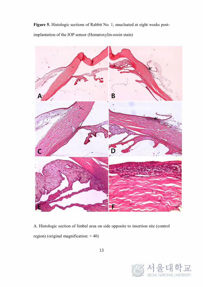
evaluation. In the section specimens for rabbit No. 1, a comparison with the
opposite side (the control region) of the same eye revealed that inflammatory
cells had infiltrated into the limbal area. Moreover, inflammatory infiltrates
were found throughout the subepithelium and anterior stroma of the cornea.
However, the stromal layer generally maintained its normal configuration, and
there were no significant deformities of tissue structures in the sclera, limbus,
cornea, or anterior-chamber-angle region. The non-pigmented iris and ciliary

10
body stroma were both anatomically intact (Figure 5).
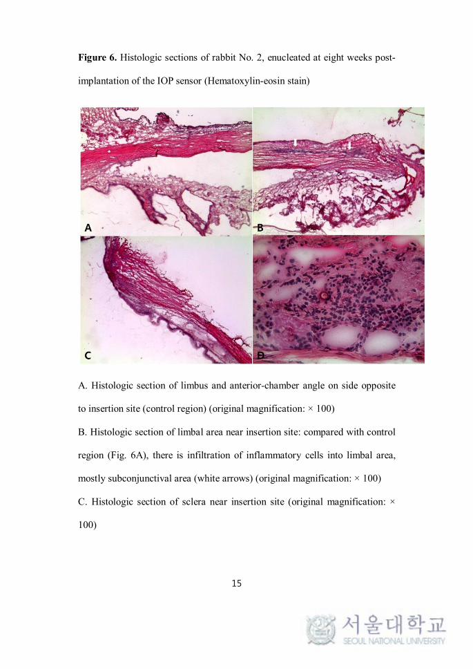
The specimens for rabbit No. 2 also showed infiltration of inflammatory cells
into the limbal area, mostly the subepithelial and anterior stromal layers.
Under high magnification (Figure 6D), the inflammatory cells were found to
be composed mainly of polymorphonuclear neutrophils (PMNs). There was
no definite deformity of tissue structures; the sclera, cornea, iris, ciliary body
and lens showed their normal configurations (Figure 6).

11
Figure 3. Follow-up external photography of Rabbit No. 1 (A, C) and Rabbit
No. 2 (B, D)
A. Four weeks post-implantation: ciliary injection around insertion site can be
seen.
B. Four weeks post-implantation: ciliary injection and mild corneal
neovascularization with haziness around insertion site is apparent.
C. Eight weeks post-implantation: ciliary injection much decreased;
transparency of cornea within normal range.
D. Eight weeks post-implantation: ciliary injection much decreased; corneal
neovascularization with haziness nearly regressed.

12
Figure 4. Gross photography of enucleated rabbit eyes at eight weeks post-
implantation of the IOP sensor.
A. Rabbit No. 1 B. Rabbit No 2: no evidence of gross inflammation,
membrane formation, or encapsulation of IOP sensor; globe integrity appears
normal.
13
Figure 5. Histologic sections of Rabbit No. 1, enucleated at eight weeks post-
implantation of the IOP sensor (Hematoxylin-eosin stain)
A. Histologic section of limbal area on side opposite to insertion site (control
region) (original magnification: × 40)

14
B. Histologic section of limbal area near insertion site: compared with control
region (Fig. 5A), there is no definite deformity of tissue structures, though
there is infiltration of inflammatory cells into limbal area (black arrow)
(original magnification: × 40)
C. Histologic section of limbal area on side opposite to insertion site (original
magnification: × 100)
D. Histologic section of limbal area near insertion site: black arrow denotes
infiltration of inflammatory cells into limbal area (original magnification: ×
100)
E. Histologic section of ciliary body and iris near insertion site: non-
pigmented iris and ciliary body stroma are anatomically intact (original
magnification: × 200)
F. Histologic section of limbal area near insertion site: inflammatory infiltrates
were commonly found subepithelially. normal configuration of stromal layer
maintained (original magnification: × 400)
15
Figure 6. Histologic sections of rabbit No. 2, enucleated at eight weeks post-
implantation of the IOP sensor (Hematoxylin-eosin stain)
A. Histologic section of limbus and anterior-chamber angle on side opposite
to insertion site (control region) (original magnification: × 100)
B. Histologic section of limbal area near insertion site: compared with control
region (Fig. 6A), there is infiltration of inflammatory cells into limbal area,
mostly subconjunctival area (white arrows) (original magnification: × 100)
C. Histologic section of sclera near insertion site (original magnification: ×
100)

16
D. Histologic section of limbal area near insertion site: infiltration of
inflammatory cells, mainly polymorphonuclear neutrophils (PMNs), is
evident in subepithelial and anterior stromal layers.

17
Discussion
Intraocular pressure (IOP) is among the most important risk factors for
development and progression of glaucoma, and, as of now, it remains the only
modifiable one.28-30 Therefore, in glaucoma-management regimes, effective
control of IOP is mandatory.28,29 Nonetheless, IOP is not a static but rather a
dynamic physiologic parameter showing a normal circadian pattern of
variation, along with occasional random short- and long-term fluctuations3, 4
that represent a significant risk factor for progression of glaucoma.9-11 Thus,
one-time “snapshot” IOP measurement cannot safely be considered to provide
a complete IOP profile.6-8, 31 Therefore, in glaucoma patients, continuous IOP
monitoring is necessary to evaluate the proper state of IOP and to determine
the effective management plan for the fluctuating IOP. Furthermore it may
help the early diagnosis and proper treatment of glaucoma.
However, continuous real-time monitoring of IOP is not possible with the
current standard applanation tonometry (Goldmann applanation tonometry:
GAT). Instead, most patients visit clinics for IOP measurement once every
few weeks or months. But again, such an intermittent measurement of the IOP
cannot provide physicians with anything approaching a complete IOP profile
of a patient. Besides, IOP GAT-measured in the sitting position does not
reflect the positional changes that occur during the sleep. Indeed, recent
studies have reported that nocturnal IOP in the supine or lateral decubitus

18
position does not correlate with daytime sitting-position IOP.32, 33
Microelectronic technology advancements in recent decades have enabled the
development of various types of telemetric (wireless) sensors for continuous
monitoring of IOP.15-27 These devices can be classified into invasive
(implantable) and non-invasive categories. The representative non-invasive
IOP sensor is that which is incorporated into a soft contact lens to measure
changes in corneal IOP-related biomechanics.17, 24-26 One such example is
Leonardi et al.’s microstrain gauge sensor, which measures changes of corneal
curvature.17 However, like GAT, the contact-lens-type sensor is affected by
corneal biomechanics,27 which means that measurements in patients with
corneal abnormalities will be skewed. Moreover, this type of sensor can lead
to complications associated with long-term contact lens use.
On the other hand, an invasive implantable IOP sensor enables continuous
IOP monitoring that, unlike the cases with GAT and the contact-lens-type IOP
sensor, is unaffected by corneal biomechanics. And because it is implanted
inside the eye, it can provide the “true internal IOP,” again unlike GAT or the
contact-lens-type sensor, both of which can measure the IOP only indirectly as
based on the relationship between the measured parameter and the true IOP.
Thus the implantation option enables precise IOP measurement in patients for
whom, due to corneal problems or a history of refractive surgery, it would be
impossible by GAT or contact-lens-type sensor. The implantable IOP sensor
also has several other advantages over standard GAT. It can help to reduce the
19
number of clinic visits a patient is obliged to make for IOP monitoring, and
can improve treatment compliance. Furthermore, with developments in
information and communications technology, it could also contribute to the
advance of telemedicine. Certainly, the ability to transmit IOP data to a central
server using the portable digital external IOP reader would be a great help for
patients living in secluded regions or areas otherwise distant from clinics.
For all the above-noted reasons, many groups have been conducting research
into the development of continuous-IOP-sensing implantable devices. Collins
et al. (1967)34 were the first to achieve such a sensor. Their “capacitive
pressure sensor” measured the change of resonant frequency induced by the
change of distance between the two parallel coaxial coils of an inductor (L)-
and capacitor (C)-resonant circuit, which change was itself induced by IOP.
This capacitive pressure sensor offers the advantages of low power
consumption, low noise, high sensitivity, low temperature drift, and good
long-term stability.35 Additionally, with the recent progress made in micro
electro mechanical systems (MEMS) and microfabrication technologies,
miniaturization of the telemetric IOP sensor by incorporation of LC-resonant-
circuit technology has been proceeding apace.15, 18, 19, 36, 37 Our IOP sensor
system, also of the capacitive type, has gone through various improvement
processes including polymerization, the results for which have shown good
elasticity and biocompatibility. Our system has the extra merit of not requiring
any external power supply: thereby, device lifetime is extended, and battery-

20
related biocompatibility problems are avoided.
Indeed, one of the most fundamental requirements of an implantable device is
to ensure long-term biocompatibility. However, there have been relatively few
reports on the biocompatibility of implantable IOP sensors.38, 39 The data from
the present in vivo experiments, sequential clinical evaluation and
histopathologic examination showed our IOP sensor to have achieved
comparatively high biocompatibility in rabbit eyes. Of course, on clinical
evaluation, both rabbit eyes immediate-postoperatively presented with
conjunctival hyperemia, corneal edema and anterior-chamber inflammation.
These, however, gradually subsided within four weeks post-implantation, and
by eight weeks postoperatively, there were no definite sequelae in the
conjunctiva, cornea or lens, excepting mild degrees of conjunctival hyperemia.
In both rabbits moreover, the anterior-chamber depths and angles were patent
throughout the follow-up.
On gross pathologic evaluation of the enucleated eyes, there was no definite
membrane formation or encapsulation around the implant. This finding also
suggested that there was and had been no definite foreign-body reaction to the
implant.
On histopathologic examination of the enucleated eyes at eight weeks
postoperatively, and comparing with the control region in each eye, there were
no significant deformities of ocular-tissue structures. As for the cornea, there
21
was no definite abnormality in the endothelial cell lining or in the
arrangement of the stromal layers, excepting the inflammatory infiltrations in
the limbus. Neither were there any significant inflammatory infiltrations or
structural deformations in the iridocorneal angle or the lens. Taking all of
these findings into account, we considered the inflammatory or foreign-body
reactions to the implantable IOP sensor to be slight. This suggested that our
IOP sensor had achieved a favorable degree of biocompatibility with the
rabbit eye.
However, this study has several limitations. First, there were only a small
number of cases (two rabbit eyes) and a relatively short-term (eight-week)
follow-up period. For confirmation of the long-term biosafety of sensors, a
long-term study with a large number of cases will be required. Second, the
ocular tissue and structures were evaluated on the basis only of the gross and
microscopic findings. For thorough and accurate evaluation of the
biochemical or ultrastructural changes of tissue structures,
immunohistochemical stains or electron microscopic observations might be
necessary. Third, this study is relatively lacking in IOP data. Sequential
evaluation of IOP is essential to any evaluation of the influence of device-
implantation procedures on IOP. For the compensate such a limitation, we
are planning to conduct a long-term follow up study at least over 3 months,
with a large number of subjects. And in this next experiment, we are going to
perform various methods of tissue analysis including the

22
immunohistochemical stains or electron microscopic observations.
In conclusion, we designed and developed a prototype implantable IOP sensor
that enables continuous telemetry (wireless communications)-based
monitoring of IOP. In this preliminary report, we demonstrate the favorable
rabbit-eye biocompatibility of this sensor, with respect to which no significant
evidence of toxicity or foreign-body reaction except mild inflammatory
infiltrations in the limbus was evident in our investigation.
However, this is the short term results with a small number of cases. Thus, in
the future, long-term animal studies involving a large number of subjects are
required.

23
References
1. Leske MC, Connell AM, Wu SY, Hyman L, Schachat AP.
Distribution of intraocular pressure. The Barbados Eye Study. Arch
Ophthalmol. 1997;115:1051-1057.
2. Hashemi H, Kashi AH, Fotouhi A, Mohammad K. Distribution of
intraocular pressure in healthy Iranian individuals: the Tehran Eye Study. Br J
Ophthalmol. 2005;89:652-657.
3. Sihota R, Saxena R, Gogoi M, Sood A, Gulati V, Pandey RM. A
comparison of the circadian rhythm of intraocular pressure in primary phronic
angle closure glaucoma, primary open angle glaucoma and normal eyes.
Indian J Ophthalmol. 2005;53:243-247.
4. Fogagnolo P, Rossetti L, Mazzolani F, Orzalesi N. Circadian
variations in central corneal thickness and intraocular pressure in patients with
glaucoma. Br J Ophthalmol. 2006;90:24-28.
5. Drance SM. The significance of the diurnal tension variations in
normal and glaucomatous eyes. Arch Ophthalmol. 1960;64:494-501.
6. Hughes E, Spry P, Diamond J. 24-hour monitoring of intraocular
pressure in glaucoma management: a retrospective review. J Glaucoma.
2003;12:232-236.
7. Barkana Y, Anis S, Liebmann J, Tello C, Ritch R. Clinical utility of
intraocular pressure monitoring outside of normal office hours in patients with

24
glaucoma. Arch Ophthalmol. 2006;124:793-797.
8. Fogagnolo P, Orzalesi N, Ferreras A, Rossetti L. The circadian curve
of intraocular pressure: can we estimate its characteristics during office hours?
Invest Ophthalmol Vis Sci. 2009;50:2209-2215.
9. Asrani S, Zeimer R, Wilensky J, Gieser D, Vitale S, Lindenmuth K.
Large diurnal fluctuations in intraocular pressure are an independent risk
factor in patients with glaucoma. J Glaucoma. 2000;9:134-142.
10. Caprioli J, Coleman AL. Intraocular pressure fluctuation a risk factor
for visual field progression at low intraocular pressures in the advanced
glaucoma intervention study. Ophthalmology. 2008;115:1123-1129.
11. Nouri-Mahdavi K, Hoffman D, Coleman AL, Liu G, Li G,
Gaasterland D, et al. Predictive factors for glaucomatous visual field
progression in the Advanced Glaucoma Intervention Study. Ophthalmology.
2004;111:1627-1635.
12. Brandt JD, Beiser JA, Kass MA, Gordon MO. Central corneal
thickness in the Ocular Hypertension Treatment Study (OHTS).
Ophthalmology. 2001;108:1779-1788.
13. Phillips LJ, Cakanac CJ, Eger MW, Lilly ME. Central corneal
thickness and measured IOP: a clinical study. Optometry. 2003;74:218-225.
14. Zhang Y, Zhao JL, Bian AL, Liu XL, Jin YM. [Effects of central
corneal thickness and corneal curvature on measurement of intraocular
pressure with Goldmann applanation tonometer and non-contact tonometer].
Zhonghua Yan Ke Za Zhi. 2009;45:713-718.

25
15. Chen PJ, Saati S, Varma R, Humayun MS, Tai YC. Wireless
intraocular pressure sensing using microfabricated minimally invasive
flexible-coiled LC sensor implant. Journal of Microelectromechanical
Systems. 2010;19:721-734.
16. Eggers T, Draeger J, Hille K, Marschner C, Stegmaier P, Binder J, et
al., editors. Wireless intra-ocular pressure monitoring system integrated into
an artificial lens. 2000: IEEE.
17. Leonardi M, Leuenberger P, Bertrand D, Bertsch A, Renaud P,
editors. A soft contact lens with a MEMS strain gage embedded for
intraocular pressure monitoring. 2003: IEEE.
18. Stangel K, Kolnsberg S, Hammerschmidt D, Hosticka B, Trieu H,
Mokwa W. A programmable intraocular CMOS pressure sensor system
implant. Solid-State Circuits, IEEE Journal of. 2001;36:1094-1100.
19. Chitnis G, Maleki T, Samuels B, Cantor L, Ziaie B. A Minimally
Invasive Implantable Wireless Pressure Sensor for Continuous IOP
Monitoring. IEEE Trans Biomed Eng. 2012;19:19.
20. Rizq RN, Choi WH, Eilers D, Wright MM, Ziaie B. Intraocular
pressure measurement at the choroid surface: a feasibility study with
implications for implantable microsystems. British journal of ophthalmology.
2001;85:868-871.
21. Kakaday T, Hewitt AW, Voelcker NH, Li JS, Craig JE. Advances in
telemetric continuous intraocular pressure assessment. Br J Ophthalmol.
2009;93:992-996.

26
22. Downs JC, Burgoyne CF, Seigfreid WP, Reynaud JF, Strouthidis NG,
Sallee V. 24-hour IOP telemetry in the nonhuman primate: implant system
performance and initial characterization of IOP at multiple timescales. Invest
Ophthalmol Vis Sci. 2011;52:7365-7375.
23. Chen PJ, Rodger DC, Meng E, Humayun MS, Tai YC, editors.
Implantable Unpowered Parylene MEMS Intraocular Pressure Sensor. 2006:
IEEE.
24. Greene ME, Gilman BG. Intraocular pressure measurement with
instrumented contact lenses. Invest Ophthalmol. 1974;13:299-302.
25. Faschinger C, Mossbock G. [Continuous 24 h monitoring of changes
in intraocular pressure with the wireless contact lens sensor Triggerfish. First
results in patients]. Ophthalmologe. 2010;107:918-922.
26. Hediger A, Kniestedt C, Zweifel S, Knecht P, Funk J, Kanngiesser H.
[Continuous intraocular pressure measurement: First results with a pressure-
sensitive contact lens]. Ophthalmologe. 2009;106:1111-1115.
27. Mansouri K, Medeiros FA, Tafreshi A, Weinreb RN. Continuous 24-
Hour Monitoring of Intraocular Pressure Patterns With a Contact Lens Sensor:
Safety, Tolerability, and Reproducibility in Patients With Glaucoma. Arch
Ophthalmol. 2012;13:1-6.
28. The Advanced Glaucoma Intervention Study (AGIS): 7. The
relationship between control of intraocular pressure and visual field
deterioration.The AGIS Investigators. Am J Ophthalmol. 2000;130:429-440.
29. Musch DC, Gillespie BW, Niziol LM, Lichter PR, Varma R.
27
Intraocular pressure control and long-term visual field loss in the
Collaborative Initial Glaucoma Treatment Study. Ophthalmology.
2011;118:1766-1773.
30. Sommer A, Tielsch JM. Risk factors for open-angle glaucoma: the
Barbados Eye Study. Arch Ophthalmol. 1996;114:235.
31. Sit AJ. Continuous monitoring of intraocular pressure: rationale and
progress toward a clinical device. J Glaucoma. 2009;18:272-279.
32. Liu JH, Kripke DF, Hoffman RE, Twa MD, Loving RT, Rex KM, et
al. Nocturnal elevation of intraocular pressure in young adults. Invest
Ophthalmol Vis Sci. 1998;39:2707-2712.
33. Liu JH, Kripke DF, Twa MD, Hoffman RE, Mansberger SL, Rex KM,
et al. Twenty-four-hour pattern of intraocular pressure in the aging population.
Invest Ophthalmol Vis Sci. 1999;40:2912-2917.
34. Collins CC. Miniature passive pressure transensor for implanting in
the eye. IEEE Trans Biomed Eng. 1967;14:74-83.
35. Puers R. Capacitive sensors: when and how to use them. Sensors and
Actuators A: Physical. 1993;37:93-105.
36. Ullerich S, Mokwa W, Vom Bogel G, Schnakenberg U, editors.
Micro coils for an advanced system for measuring intraocular pressure. 2000:
IEEE.
37. Simons RN, Hall DG, Miranda FA, editors. RF telemetry system for
an implantable bio-MEMS sensor. 2004: IEEE.
38. Todani A, Behlau I, Fava MA, Cade F, Cherfan DG, Zakka FR, et al.

28
Intraocular pressure measurement by radio wave telemetry. Invest Ophthalmol
Vis Sci. 2011;52:9573-80.
39. Chen PJ, Rodger DC, Saati S, Humayun MS, Tai YC.
Microfabricated implantable parylene-based wireless passive intraocular
pressure sensors. Journal of Microelectromechanical Systems, 2008;17:1342-
1351.

29
목 : 본 연구는 실시간 지속 안압 해 새롭게 개 한
삽입 안압 토끼 안구에 생체 합 알아보고자 하
다.
법: 공진주파 변 통한 식 실시간 안압 이
가능한 5mm x 3.5mm크 직사각 태 삽입 안압 를 개
하 다. 뉴질랜드 흰색 토끼 2마리 2안 상 안압 를 삽
입 후 2주, 4주, 8주에 미경 찰과 외안부 사진 시행하 다.
삽입 8주 후 안구를 출하여 안 병리 소견 찰하 며 삽입
안압 를 거 후 조직학 인 소견 찰하 다.
결과: 안압 를 토끼 안구 내에 삽입 후 8주 지 지속 미경
찰 결과 한 염증 이나 없이 안 임상
양상 보 다. 조직학 검사상 심한 염증 이나 이 질 ,
안구 조직구조 변 는 찰 지 않았다.
결 : 새롭게 개 원 안압 는 토끼 안구 내에 삽입 시
한 독 이나 이 질 없이 우 한 생체 합
보 다.
주요어: 생체 합 , 지속 안압 , 녹내장, 안압, 삽입
학 번: 2011-21968


![1[1].jpgother eye problems. Tonometry: The doctor will test your eye pressure with an airpuff pneumotonometer. Alternatively an instrument that measures the pressure called an Applanation](https://img.dokumen.tips/doc/110x75/5f3549f74039f7469007bc06/11-other-eye-problems-tonometry-the-doctor-will-test-your-eye-pressure-with.jpg)