Embed Size (px)
Citation preview
717
Disc Couplings Servo Motor Compatible
High Torque Disc Clamping (Double Disc)
Comparison Points with Similar Products
Part Number (1Type·2D) - 3d1 - 4d2
MCSLC40
MCSLCWK40
-
-
10
10
-
-
15
12
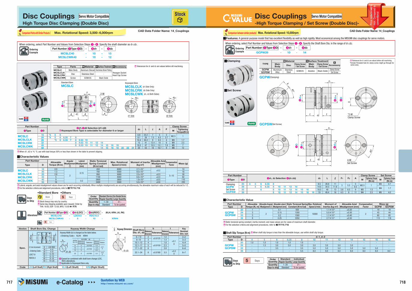
When ordering, select Part Number and Values from Selection Steps 1~4. Specify the shaft diameter as d1≤d2.
Type Parts MMaterial SSurface Treatment AAccessory
MCSLC
MCSLCLK
MCSLCRK
MCSLCWK
Main Body Aluminum Diecast Electroless Nickel PlatingHexagon Socket Head Cap ScrewDisc Stainless Steel -
Screw SCM435 Black Oxide
Standard Bore
MCSLC Keywayed Bore
MCSLCLK (d1 Side Only)
MCSLCRK (d2 Side Only)
MCSLCWK (d1, d2 Both Sides)
A
2-M
L
F
L
L
H4
d2
8
d3
H3
d1
8
2D
45°
d1 Side d2 Side
45°
CADCAD2D3D
E Tolerances for d1 and d2 are values before slit machining.
Part Number3d1,4d2 Selection (d1≤d2)
EKeywayed Bore Type is selectable for diameter 6 or largerd3 L L A F
Clamp Screw
1Type 2D MTightening
Torque(N∙m)
MCSLC
MCSLCLK
MCSLCRK
MCSLCWK
16 *4 5 6 6.8 23.2 7 5 3M2.5 1
20 *4 5 6 6.35 7 8 8.1 26 7.5 6.5 3.725 *5 6 6.35 7 8 9.53 10 10.4 30.2 9 8.5 4 M3 1.732 8 9.53 10 11 12 14 15 41 12.4 10 6 M4 2.540 8 9.53 10 11 12 14 15 16 18 19.5 47 15.5 13.1 7.8 M5 750 14 15 16 18 20 22 24 25 53 18 16.7 9 M6 12
EWhen d1, d2 is *4, *5, use with load torque 50% or less than shown in the table to prevent slipping.
QCharacteristic Values
Part Number (1Type·2D) - 3d1(LDC) - 4d2(RDC) - (KLH, KRH, LK, RK)
MCSLC40 - LDC9.5 - RDC10.5
MCSLCWK40 - 8 - 10 - KRH4
5
Alterations Shaft Bore Dia. Change Keyway Width Change
Spec.
Code LDC(Left Shaft) RDC(Right Shaft) KLH(Left Shaft) KRH(Right Shaft)
D LDC·RDC16 4~620 4~825 5~1032 6~1440 8~1850 14~24
LDC H
8
RDC H
8
Keyway Width (b) is changed as the table below.<Ordering Code> KLH4 KRH4
XCannot be combined with shaft bore change (LDC, RDC) alterations.
EApplicable to Keywayed Bore only.
0.1mm Increment
<Ordering Code>
LDC7.8
RDC9.3
Shaft Bore Dia. d1, d2
KLH·KRH (b) tReferenceDimension Tolerance Reference
Dimension Tolerance
8 2 ±0.0125 1.0 +0.1
010 4±0.0150
1.8 12 5 2.3
22 8 ±0.0180 3.3 +0.2 0
b
t
d1 d2
Shaft Bore
Dia. d1, d2
b t Key
Nominal
Dim. bxhReference
DimensionTolerance
Reference
DimensionTolerance
6~7.9 2±0.0125
1.0
+0.1 0
2×28~10 3 1.4 3×3
10.1~12 4±0.0150
1.8 4×412.1~17 5 2.3 5×517.1~22 6 2.8 6×6
22.1~24 8 ±0.0180 3.3 +0.2 0 8×7
d1,d2
t
b
Keyway Dimension
Part NumberAllowable
Torque (N∙m)
Angular
Misalignment
(°)
Lateral
Misalignment
(mm)
Static Torsional
Spring Constant
(N∙m/rad)
Max. Rotational
Speed (r/min)
Moment of Inertia
(kg∙m2)
Allowable Axial
Misalignment
(mm)
Compensation
FactorMass (g)
Type D
MCSLC
MCSLCLK
MCSLCRK
MCSLCWK
16 0.9
20.15
450 6000 2.7×10⁻⁷
±0.2
5~10
1020 1.3 700 5500 8.0×10⁻⁷ 1625 2.8 950 5000 2.5×10⁻⁶ ±0.3 3032 5 1100 4000 6.6×10⁻⁶ ±0.4 6240 9 0.2 2800 3800 1.9×10⁻⁵ ±0.5 11050 16 3400 3500 5.0×10⁻⁵ ±0.6 220
E Lateral, angular, and axial misalignment values shown are for each occurring individually. When multiple misalignments are occurring simultaneously, the allowable maximum value of each will be reduced to 1/2.E For the selection criteria and alignment procedures, refer to dP.715,716
CAD Data Folder Name: 14_CouplingsMax. Rotational Speed: 3,500~6,000rpm
Order Quantity
Standard Service Non-Standard Service
Regular Quantity Large Quantity
Quantity 1~30 31~Days to ship Standard To be quoted
E Stock lineup may vary by country.E Same day shipping available upon request. Order by
THA: 16:00, SGP: 12:00, MYS: 15:00 d P.75
5
718
Disc Couplings-High Torque Clamping / Set Screw (Double Disc)-
Servo Motor Compatible
CADCAD2D3D
Part Number (1Type·2D) - 3d1 - 4d2
GCPW29 - 10 - 14
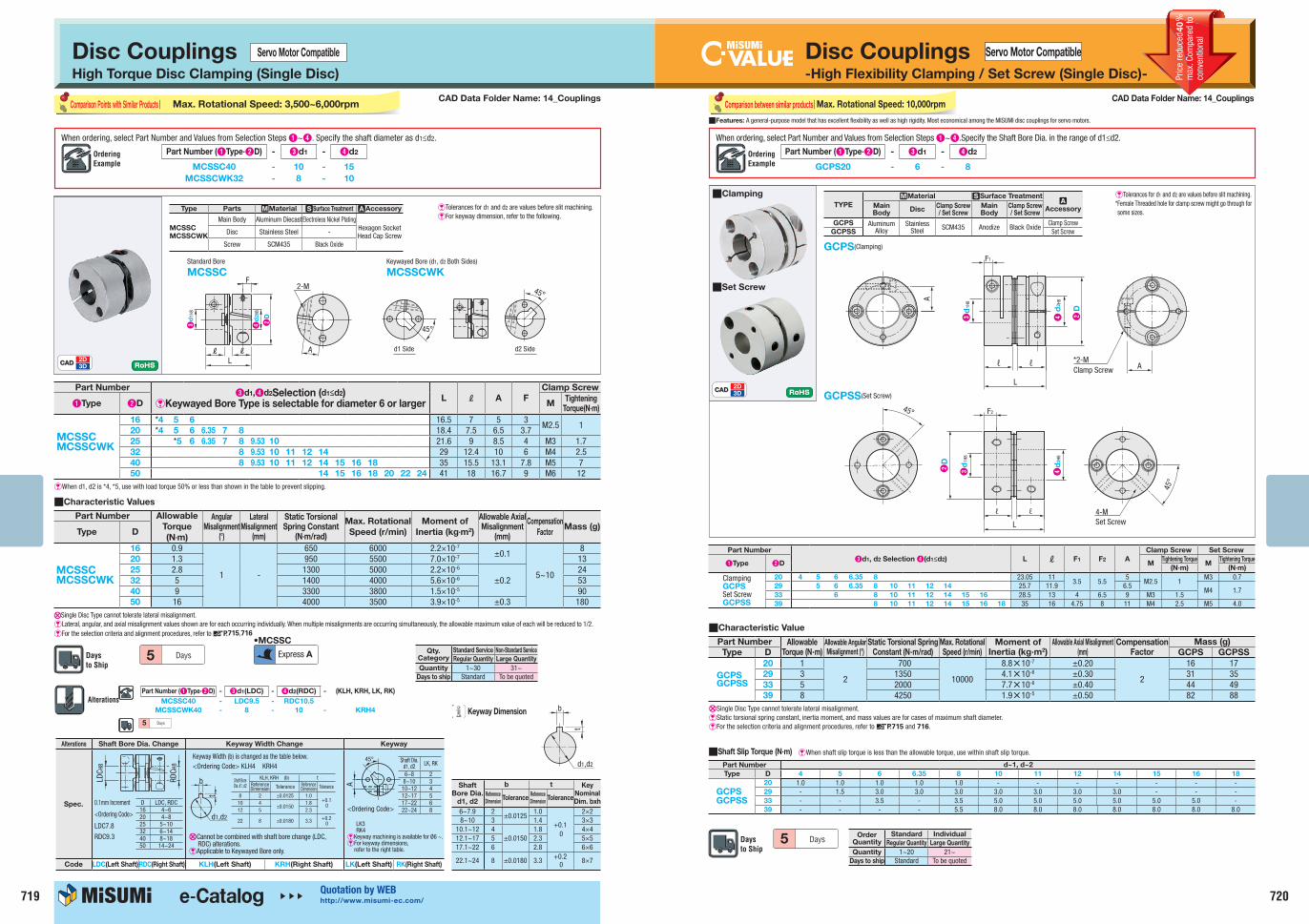
When ordering, select Part Number and Values from Selection Steps 1~4. Specify the Shaft Bore Dia. in the range of d1≤d2.
CAD Data Folder Name: 14_Couplings
ETolerances for d1 and d2 are values before slit machining.* Female Threaded hole for clamp screw might go through for some sizes.
GCPW(Clamping)
GCPSW(Set Screw)
Comparison between similar products
QFeatures: A general-purpose model that has excellent flexibility as well as high rigidity. Most economical among the MISUMI disc couplings for servo motors.
QCharacteristic Value
Part Number Allowable
Torque (N, m)
Allowable Angular
Misalignment (°)
Allowable Lateral
Misalignment (mm)
Static Torsional Spring
Constant (N·m/rad)
Max. Rotational
Speed (r/min)
Moment of
Inertia (kg·m2)
Allowable Axial
Misalignment (mm)
Compensation
Factor
Mass (g)
Type D GCPW GCPSW
GCPWGCPSW
20 1
2
0.1 550
10000
1.1N10-6 ±0.20
2
19 1929 3 0.15 1200 5.5N10-6 ±0.30 43 4433 5 0.2 1500 1.1N10-5 ±0.40 60 6539 8 0.25 3350 2.7N10-5 ±0.50 113 118
EStatic torsional spring constant, inertia moment, and mass values are for cases of maximum shaft diameter.E For the selection criteria and alignment procedures, refer to dP.715,716
5 Order Quantity
Standard Individual
Regular Quantity Large Quantity
Quantity 1~20 21~Days to ship Standard To be quoted
TYPE
MMaterial SSurface TreatmentA
AccessoryMain Body
DiscClamp Screw / Set Screw
Main Body
Clamp Screw / Set Screw
GCPW Aluminum Alloy
Stainless Steel SCM435 Anodize Black Oxide
Clamp ScrewGCPSW Set Screw
Part Number
3d1, d2 Selection 4(d1≤d2) d3 L l F1 F2 A
Clamp Screw Set Screw
1Type 2D MTightening Torque
MTightening Torque
(N·m) (N·m)
ClampingGCPWSet ScrewGCPSW
20 4 5 6 6.35 8 8.5 28.8 113 5.5
5M2.5 1
M3 0.7 29 5 6 6.35 8 10 11 12 14 14.5 34.3 11.9 6.5
M4 1.7 33 6 8 10 11 12 14 15 16 16.5 40 13 3.8 6.5 9 M3 1.539 8 10 11 12 14 15 16 18 19 49.4 16 4.5 8 11 M4 2.5 M5 4.0
E When shaft slip torque is less than the allowable torque, use within shaft slip torque.QShaft Slip Torque (N·m)
Part Number d~1, d~2
Type D 4 5 6 6.35 8 10 11 12 14 15 16 18
GCPWGCPSW
20 1.0 1.0 1.0 1.0 1.0 - - - - - - -29 - 1.5 3.0 3.0 3.0 3.0 3.0 3.0 3.0 - - -33 - - 3.5 - 3.5 5.0 5.0 5.0 5.0 5.0 5.0 -39 - - - - 5.5 8.0 8.0 8.0 8.0 8.0 8.0 8.0
Max. Rotational Speed: 10,000rpm
A
L
4d
2H8
d3 ℓℓ
F1
A
*2-MClamp Screw
45°
3d
1H8
2D
D d2
H8
d3
4
d1
H832
F2
L
ℓℓ 4-MSet Screw
45°
QClamping
QSet Screw
40
719
Disc Couplings Servo Motor Compatible
High Torque Disc Clamping (Single Disc)
Comparison Points with Similar Products Max. Rotational Speed: 3,500~6,000rpm
Part Number (1Type·2D) - 3d1 - 4d2
MCSSC40
MCSSCWK32
-
-
10
8
-
-
15
10
When ordering, select Part Number and Values from Selection Steps 1~4. Specify the shaft diameter as d1≤d2.
Standard Bore
MCSSCKeywayed Bore (d1, d2 Both Sides)
MCSSCWK
CADCAD2D3D
E Tolerances for d1 and d2 are values before slit machining.E For keyway dimension, refer to the following.
QCharacteristic Values
Part Number (1Type·2D) - 3d1(LDC) - 4d2(RDC) - (KLH, KRH, LK, RK)
MCSSC40 - LDC9.5 - RDC10.5
MCSSCWK40 - 8 - 10 - KRH4
5
A
2-MF
LLL
H3
d1
8 H4
d2
8
2D
d1 Side d2 Side
45°
45°
Part Number3d1,4d2Selection (d1≤d2)
EKeywayed Bore Type is selectable for diameter 6 or largerL L A F
Clamp Screw
1Type 2D MTightening
Torque(N∙m)
MCSSCMCSSCWK
16 *4 5 6 16.5 7 5 3M2.5 1
20 *4 5 6 6.35 7 8 18.4 7.5 6.5 3.725 *5 6 6.35 7 8 9.53 10 21.6 9 8.5 4 M3 1.732 8 9.53 10 11 12 14 29 12.4 10 6 M4 2.540 8 9.53 10 11 12 14 15 16 18 35 15.5 13.1 7.8 M5 750 14 15 16 18 20 22 24 41 18 16.7 9 M6 12
EWhen d1, d2 is *4, *5, use with load torque 50% or less than shown in the table to prevent slipping.
Part Number Allowable
Torque
(N∙m)
Angular Misalignment
(°)
Lateral Misalignment
(mm)
Static Torsional Spring Constant
(N∙m/rad)
Max. Rotational
Speed (r/min)
Moment of
Inertia (kg∙m2)
Allowable Axial Misalignment
(mm)
Compensation
FactorMass (g)
Type D
MCSSCMCSSCWK
16 0.9
1 -
650 6000 2.2×10⁻⁷
±0.1
5~10
820 1.3 950 5500 7.0×10⁻⁷ 1325 2.8 1300 5000 2.2×10⁻⁶
±0.224
32 5 1400 4000 5.6×10⁻⁶ 5340 9 3300 3800 1.5×10⁻⁵ 9050 16 4000 3500 3.9×10⁻⁵ ±0.3 180
xSingle Disc Type cannot tolerate lateral misalignment.E Lateral, angular, and axial misalignment values shown are for each occurring individually. When multiple misalignments are occurring simultaneously, the allowable maximum value of each will be reduced to 1/2.E For the selection criteria and alignment procedures, refer to dP.715,716
Alterations Shaft Bore Dia. Change Keyway Width Change Keyway
Spec.<Ordering Code>
Code LDC(Left Shaft)RDC(Right Shaft) KLH(Left Shaft) KRH(Right Shaft) LK(Left Shaft) RK(Right Shaft)
D LDC, RDC16 4~620 4~825 5~1032 6~1440 8~1850 14~24
LDC H
8
RDC H
8
Keyway Width (b) is changed as the table below.<Ordering Code> KLH4 KRH4
XCannot be combined with shaft bore change (LDC, RDC) alterations.
EApplicable to Keywayed Bore only.
Shaft Bore Dia. d1, d2
KLH, KRH (b) tReferenceDimension Tolerance Reference
Dimension Tolerance
8 2 ±0.0125 1.0 +0.1
010 4±0.0150
1.8 12 5 2.3
22 8 ±0.0180 3.3 +0.2 0
b
t
d1,d2
A
45°
LK3RK4
EKeyway machining is available for Ø6 ~.E For keyway dimensions,
refer to the right table.
Shaft Dia. d1, d2 LK, RK
6~8 28~10 310~12 412~17 517~22 622~24 8
Shaft
Bore Dia.
d1, d2
b t Key
Nominal
Dim. bxhReference
DimensionTolerance
Reference
DimensionTolerance
6~7.9 2±0.0125
1.0
+0.10
2×28~10 3 1.4 3×3
10.1~12 4±0.0150
1.8 4×412.1~17 5 2.3 5×517.1~22 6 2.8 6×6
22.1~24 8 ±0.0180 3.3 +0.20 8×7
d1,d2
t
bKeyway Dimension
Type Parts MMaterial SSurface Treatment AAccessory
MCSSC
MCSSCWK
Main Body Aluminum DiecastElectroless Nickel PlatingHexagon Socket Head Cap ScrewDisc Stainless Steel -
Screw SCM435 Black Oxide
Qty. Category
Standard Service Non-Standard Service
Regular Quantity Large Quantity
Quantity 1~30 31~Days to ship Standard To be quoted
5 Express A
0.1mm Increment
<Ordering Code>
LDC7.8
RDC9.3
CAD Data Folder Name: 14_Couplings
720
Disc Couplings-High Flexibility Clamping / Set Screw (Single Disc)-
Servo Motor Compatible
GCPS(Clamping)
GCPSS(Set Screw)
TYPE
MMaterial SSurface TreatmentA
AccessoryMain Body
DiscClamp Screw / Set Screw
Main Body
Clamp Screw / Set Screw
GCPS Aluminum Alloy
Stainless Steel SCM435 Anodize Black Oxide
Clamp ScrewGCPSS Set Screw
Part Number
3d1, d2 Selection 4(d1≤d2) L l F1 F2 A
Clamp Screw Set Screw
1Type 2D MTightening Torque
MTightening Torque
(N∙m) (N∙m)
ClampingGCPSSet ScrewGCPSS
20 4 5 6 6.35 8 23.05 113.5 5.5
5M2.5 1
M3 0.7 29 5 6 6.35 8 10 11 12 14 25.7 11.9 6.5
M4 1.7 33 6 8 10 11 12 14 15 16 28.5 13 4 6.5 9 M3 1.539 8 10 11 12 14 15 16 18 35 16 4.75 8 11 M4 2.5 M5 4.0
Comparison between similar products
Part Number d~1, d~2
Type D 4 5 6 6.35 8 10 11 12 14 15 16 18
GCPSGCPSS
20 1.0 1.0 1.0 1.0 1.0 - - - - - - -29 - 1.5 3.0 3.0 3.0 3.0 3.0 3.0 3.0 - - -33 - - 3.5 - 3.5 5.0 5.0 5.0 5.0 5.0 5.0 -39 - - - - 5.5 8.0 8.0 8.0 8.0 8.0 8.0 8.0
E When shaft slip torque is less than the allowable torque, use within shaft slip torque.QShaft Slip Torque (N∙m)
QFeatures: A general-purpose model that has excellent flexibility as well as high rigidity. Most economical among the MISUMI disc couplings for servo motors.
CADCAD2D3D
Part Number (1Type·2D) - 3d1 - 4d2
GCPS20 - 6 - 8
When ordering, select Part Number and Values from Selection Steps 1~4.Specify the Shaft Bore Dia. in the range of d1≤d2.
ETolerances for d1 and d2 are values before slit machining.* Female Threaded hole for clamp screw might go through for some sizes.
Part Number Allowable Torque (N∙m)
Allowable Angular
Misalignment (°)
Static Torsional Spring Constant (N∙m/rad)
Max. Rotational Speed (r/min)
Moment of Inertia (kg∙m2)
Allowable Axial Misalignment(mm)
Compensation Factor
Mass (g)
Type D GCPS GCPSS
GCPSGCPSS
20 1
2
700
10000
8.8N10-7 ±0.20
2
16 1729 3 1350 4.1N10-6 ±0.30 31 3533 5 2000 7.7N10-6 ±0.40 44 4939 8 4250 1.9N10-5 ±0.50 82 88
QCharacteristic Value
XSingle Disc Type cannot tolerate lateral misalignment.EStatic torsional spring constant, inertia moment, and mass values are for cases of maximum shaft diameter.E For the selection criteria and alignment procedures, refer to dP.715 and 716.
Order Quantity
Standard Individual
Regular Quantity Large Quantity
Quantity 1~20 21~Days to ship Standard To be quoted
5
CAD Data Folder Name: 14_CouplingsMax. Rotational Speed: 10,000rpm
L
ℓℓ A
F1
A
*2-MClamp Screw
Dd2
H843
d1
H8
2
4-MSet Screw
45°
F245°
L
ℓℓ
4d
2H8
3d
1H8
2D
QClamping
QSet Screw
40