Embed Size (px)
Citation preview
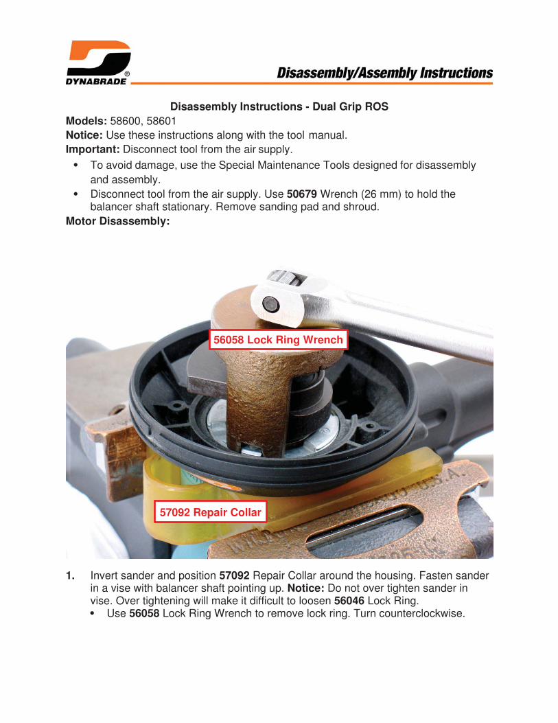
Disassembly Instructions - Dual Grip ROS
Models: 58600, 58601
Notice: Use these instructions along with the tool manual.
Important: Disconnect tool from the air supply.
To avoid damage, use the Special Maintenance Tools designed for disassembly
and assembly.
Disconnect tool from the air supply. Use 50679 Wrench (26 mm) to hold thebalancer shaft stationary. Remove sanding pad and shroud.
Motor Disassembly:
1. Invert sander and position 57092 Repair Collar around the housing. Fasten sanderin a vise with balancer shaft pointing up. Notice: Do not over tighten sander invise. Over tightening will make it difficult to loosen 56046 Lock Ring.
Use 56058 Lock Ring Wrench to remove lock ring. Turn counterclockwise.
57092 Repair Collar
56058 Lock Ring Wrench

2. Remove motor from housing.

3. Fasten 96346 Bearing Separator (2") around 56595 Cylinder.Place bearing separator and motor in 96232 Arbor Press (#2) with counterweightpointing down.
Use retaining ring pliers to remove 95626 Retaining Ring.
96346 Bearing Separator
96232 Arbor Press
Retaining Ring Pliers

4. Use arbor press and Ø 5/16" or 8 mm flat-end drive punch to push shaft out of01206 Bearing.
5/16" (8 mm) Drive Punch
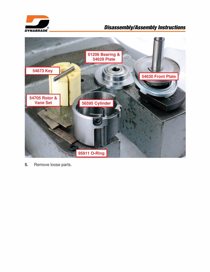
5. Remove loose parts.
56595 Cylinder
54673 Key
95911 O-Ring
54705 Rotor &Vane Set
01206 Bearing &54629 Plate
54630 Front Plate

6. Use bearing separator and arbor press to remove 02695 Bearing, 59057 Seal and59083 Felt Washer.
59057 Seal &59083 Felt

7. By hand, use 96214 Bearing Removal Tool to remove 01206 Bearing from 54629Rear Plate.
96214 Bearing Removal Tool

8. Balancer Bearing and Shaft Disassembly:With hex of 57069 Balancer Shaft pointing up, fasten counterweight in vise.Use a thin slot-blade screwdriver to remove 95630 Snap Ring.
95630 Snap Ring
57069 Balancer Shaft

8. (continued) Slide screwdriver around counterweight to release snap ring.

9. To break adhesive bond, use two large slot-blade screwdrivers to pry outbalancer shaft and bearing. Notice: If necessary, use a HEAT GUN to warmcounterweight and soften adhesive.
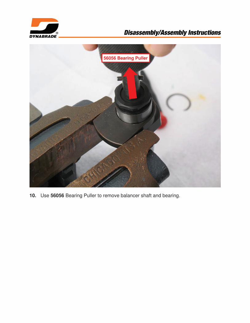
10. Use 56056 Bearing Puller to remove balancer shaft and bearing.
56056 Bearing Puller
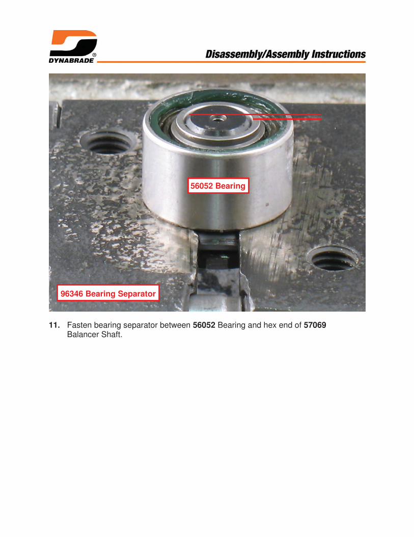
11. Fasten bearing separator between 56052 Bearing and hex end of 57069Balancer Shaft.
96346 Bearing Separator
56052 Bearing

12. With hex end of balancer shaft pointing down, place bearing separator with shaftand bearing in arbor press.
Use press ram to break adhesive bond.
Use press ram to breakadhesive bond.
96346 Bearing Separator
Assembly Instructions - Dual Grip ROSHeader
1. xxxxxx
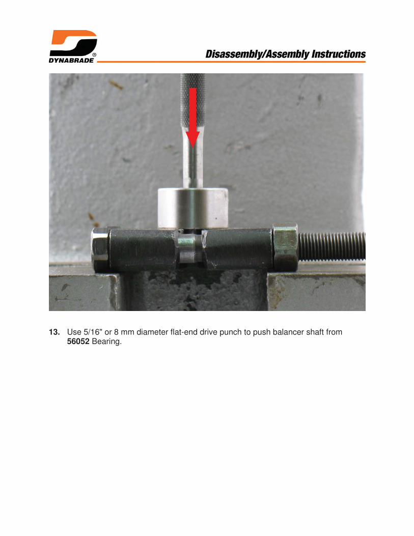
13. Use 5/16" or 8 mm diameter flat-end drive punch to push balancer shaft from56052 Bearing.

14. Remove the 59084 V-Seal.
Motor disassembly completed.
Clean and inspect parts before assembling.
57069 Balancer Shaft
59084 V-Seal
56052 Bearing

Assembly Instructions – Dual Grip ROS
Motor Assembly:
1. Balancer Shaft and Bearing Assembly:Install 95630 Snap Ring onto 59084 V-Seal.
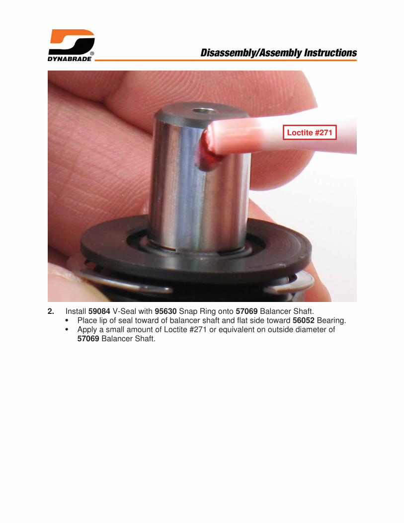
2. Install 59084 V-Seal with 95630 Snap Ring onto 57069 Balancer Shaft.Place lip of seal toward of balancer shaft and flat side toward 56052 Bearing.Apply a small amount of Loctite #271 or equivalent on outside diameter of57069 Balancer Shaft.
Loctite #271
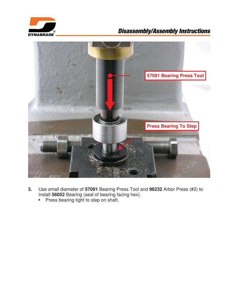
3. Use small diameter of 57091 Bearing Press Tool and 96232 Arbor Press (#2) toinstall 56052 Bearing (seal of bearing facing hex).
Press bearing tight to step on shaft.
57091 Bearing Press Tool
Press Bearing To Step

4. Apply a small amount of Loctite #271 or equivalent to outside diameter of 56052Bearing.
Install balancer shaft with bearing into motor shaft balancer.
Loctite #271

5. Use a small flat-bladed screwdriver to compress 95630 Snap Ring into groove.
Compress 95630 Snap Ring into groove.

6. Install 56046 Lock Ring onto shaft balancer. Place 59083 Felt into 59057 FrontBearing Seal and install onto shaft balancer.
Use small end of 57091 Bearing Press Tool to install 02695 Bearing.
59057 Front Bearing Seal
59083 Felt
57091 Bearing Press Tool
56046 Lock Ring
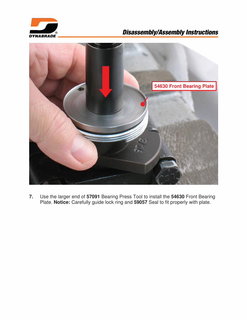
7. Use the larger end of 57091 Bearing Press Tool to install the 54630 Front BearingPlate. Notice: Carefully guide lock ring and 59057 Seal to fit properly with plate.
54630 Front Bearing Plate
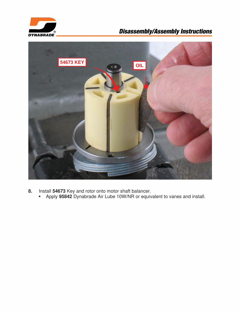
8. Install 54673 Key and rotor onto motor shaft balancer.Apply 95842 Dynabrade Air Lube 10W/NR or equivalent to vanes and install.
OIL54673 KEY

9. Apply clean grease or viscous oil to 95911 O-Ring and install in cylinder.
95911 O-Ring
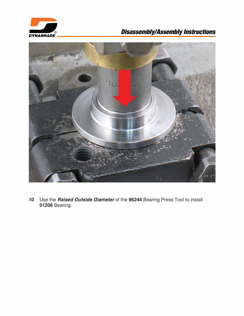
10 Use the Raised Outside Diameter of the 96244 Bearing Press Tool to install01206 Bearing.
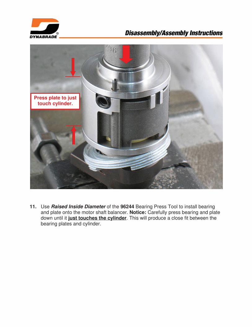
11. Use Raised Inside Diameter of the 96244 Bearing Press Tool to install bearingand plate onto the motor shaft balancer. Notice: Carefully press bearing and platedown until it just touches the cylinder. This will produce a close fit between thebearing plates and cylinder.
Press plate to justtouch cylinder.

12. Install 95626 Retaining Ring into groove on shaft.

13. Sight line-up pin with the hole on inside of housing and install motor.

14. Invert sander and place 57092 Repair Collar around housing. Fasten sander invise with counterweight pointing up. Notice: Do not over tighten sander in vise or itwill be difficult to install 56046 Lock Ring.Use 56058 Lock Ring Wrench to tighten lock ring. Turn clockwise.(T to 34 N•m/~300 lbs. in.)
15. Install shroud.Use 50679 Wrench to hold balancer shaft stationary.Install sanding pad. Turn pad clockwise.
Motor assembly completed.
Vacuum & Exhaust Assemblies:To identify vacuum and exhaust components refer to exploded view and parts list foundin tool manual.
Tool assembly completed.
Torque to 34 N•m/~300 lbs. in.