Embed Size (px)
Citation preview
Disassembling your BoXZY X and Y axisGantry
This guide will follow a procedure for disassembling the components of the BoXZY X and Y axisGantry system. This is a precursor guide to greasing or replacing your Ball Bearings
Written By: BoXZY
Disassembling your BoXZY X and Y axis Gantry Draft: 2017-07-27Guide ID: 98 -
This document was generated on 2019-09-17 09:51:25 PM (MST).
© 2019 boxzy.dozuki.com/ Page 1 of 12
Step 1 — First thing First
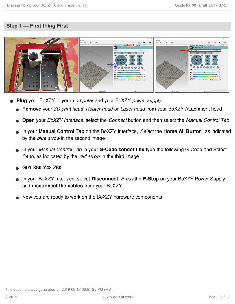
Plug your BoXZY to your computer and your BoXZY power supply
Remove your 3D print head, Router head or Laser head from your BoXZY Attachment head
Open your BoXZY Interface, select the Connect button and then select the Manual Control Tab
In your Manual Control Tab on the BoXZY Interface, Select the Home All Button, as indicatedby the blue arrow in the second image
In your Manual Control Tab in your G-Code sender line type the following G-Code and SelectSend, as indicated by the red arrow in the third image
G01 X80 Y42 Z80
In your BoXZY Interface, select Disconnect, Press the E-Stop on your BoXZY Power Supplyand disconnect the cables from your BoXZY
Now you are ready to work on the BoXZY hardware components
Disassembling your BoXZY X and Y axis Gantry Draft: 2017-07-27Guide ID: 98 -
This document was generated on 2019-09-17 09:51:25 PM (MST).
© 2019 boxzy.dozuki.com/ Page 2 of 12
Step 2 — Removing your BoXZY's Acrylic Panel
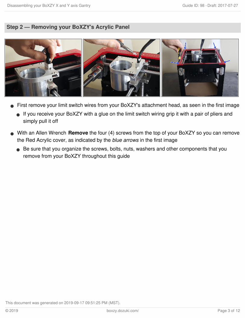
First remove your limit switch wires from your BoXZY's attachment head, as seen in the first image
If you receive your BoXZY with a glue on the limit switch wiring grip it with a pair of pliers andsimply pull it off
With an Allen Wrench Remove the four (4) screws from the top of your BoXZY so you can removethe Red Acrylic cover, as indicated by the blue arrows in the first image
Be sure that you organize the screws, bolts, nuts, washers and other components that youremove from your BoXZY throughout this guide
Disassembling your BoXZY X and Y axis Gantry Draft: 2017-07-27Guide ID: 98 -
This document was generated on 2019-09-17 09:51:25 PM (MST).
© 2019 boxzy.dozuki.com/ Page 3 of 12

Step 3 — Removing an important bolt
Turn your BoXZY around so that the back of the machine is facing you and Remove the Boltthrough the square hole in the aluminum panel above the electronics box, as indicated by the redbox in the second image
This bolt is going to be very tight, this is intentional, and you will need to apply a fair amount offorce to turn this bolt
If you are not able to see the bolt through the square hole in the panel, manually turn the BallScrew for the Y axis so that it is showing
If you cannot get leverage with your Allen Wrench, use a hollow metal tube to extend the AllenWrench so you can gain more leverage
Disassembling your BoXZY X and Y axis Gantry Draft: 2017-07-27Guide ID: 98 -
This document was generated on 2019-09-17 09:51:25 PM (MST).
© 2019 boxzy.dozuki.com/ Page 4 of 12
Step 4 — Loosening the Set Screws
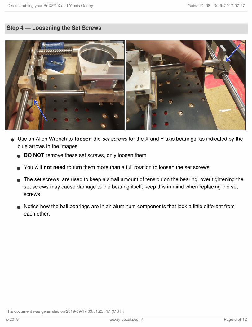
Use an Allen Wrench to loosen the set screws for the X and Y axis bearings, as indicated by theblue arrows in the images
DO NOT remove these set screws, only loosen them
You will not need to turn them more than a full rotation to loosen the set screws
The set screws, are used to keep a small amount of tension on the bearing, over tightening theset screws may cause damage to the bearing itself, keep this in mind when replacing the setscrews
Notice how the ball bearings are in an aluminum components that look a little different fromeach other.
Disassembling your BoXZY X and Y axis Gantry Draft: 2017-07-27Guide ID: 98 -
This document was generated on 2019-09-17 09:51:25 PM (MST).
© 2019 boxzy.dozuki.com/ Page 5 of 12

Step 5 — Removing the Y axis flange
On the front right facing corner of your BoXZY there will be a flange (a piece of metal) on the sideof your machine, as seen in the first image and indicated by the red arrow
With an Allen Wrench remove the top bolt from the flange while holding the bracket on the inside ofyour BoXZY, as seen in the first image, and indicated by the blue arrow
Be aware that bracket is threaded onto the top bolt and that there are washers spacing theflange and your BoXZY aluminum frame
Next, remove the bottom bolt from the flange and keep your removed pieces together, as seen inthe second image
The red arrow indicates the top flange bolt, this bolt is longer because it threads through yourBoXZY aluminum frame and threads into the bracket
The blue arrow indicates the bottom flange bolt, this is only threaded through the flange andinto your BoXZY aluminum frame
The green arrow indicates the flange itself, take note that flange is shaped with a notch in it sothat it may contour your BoXZY aluminum frame, this notch will be on the bottom of the flange
The yellow arrow indicates the set screw in the flange, do not turn this set screw, it may beneeded later during the re-assembly of your components, just leave it alone for now
Disassembling your BoXZY X and Y axis Gantry Draft: 2017-07-27Guide ID: 98 -
This document was generated on 2019-09-17 09:51:25 PM (MST).
© 2019 boxzy.dozuki.com/ Page 6 of 12

Step 6 — Removing the Y axis rod and bearing
Now you can pull the Y axis rod out of your BoXZY frame, as shown in the first image andindicated by the red arrows
The Y axis bearing, indicated by the blue arrow may turn and hang downward when you removeyour rod, do not be alarmed if it does
Next turn your Y axis bearing, indicated by the blue arrow in the second image, so it is facingdownward and simply pull it off of the rod, as indicated by the red arrow
If you cannot turn your bearing loosen the set screw on the bearing 1/8 of a full turn and tryremoving it again
Disassembling your BoXZY X and Y axis Gantry Draft: 2017-07-27Guide ID: 98 -
This document was generated on 2019-09-17 09:51:25 PM (MST).
© 2019 boxzy.dozuki.com/ Page 7 of 12

Step 7 — Removing the attachment head X axis rod
First, on the back of your machine, fully remove the bolt that you loosened in the second step ofthis guide, as indicated by the blue circle in the first image
Next, support your attachment head as indicated by the blue arrow in the second image, andgently pull the X axis rod out of the attachment head, as indicated by the red arrow in the secondimage
If your attachment head rotates downward, as seen in the third image, do not be alarmed but alsodo not rotate it intentionally
This will not harm the ball bearings in the attachment mount but the ball bearings are notintended to rotate in this manner so please avoid doing so if you you are not greasing the ballbearings or replacing them
Disassembling your BoXZY X and Y axis Gantry Draft: 2017-07-27Guide ID: 98 -
This document was generated on 2019-09-17 09:51:25 PM (MST).
© 2019 boxzy.dozuki.com/ Page 8 of 12
Step 8 — Removing the X axis Flange
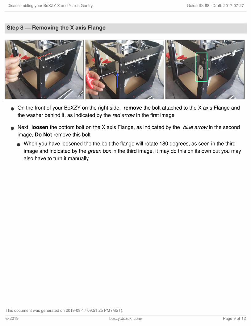
On the front of your BoXZY on the right side, remove the bolt attached to the X axis Flange andthe washer behind it, as indicated by the red arrow in the first image
Next, loosen the bottom bolt on the X axis Flange, as indicated by the blue arrow in the secondimage, Do Not remove this bolt
When you have loosened the the bolt the flange will rotate 180 degrees, as seen in the thirdimage and indicated by the green box in the third image, it may do this on its own but you mayalso have to turn it manually
Disassembling your BoXZY X and Y axis Gantry Draft: 2017-07-27Guide ID: 98 -
This document was generated on 2019-09-17 09:51:25 PM (MST).
© 2019 boxzy.dozuki.com/ Page 9 of 12

Step 9 — Removing the X axis Rod and Attachment head
Support the X axis Bearing with one hand and remove the X axis Rod with your other hand, asseen the first image and indicated by the red and blue arrows
Next, support the Rod and Attachment mount with one hand and remove the X axis Bearing fromthe end of the rod with your other hand, as indicated by the red and blue arrows in the secondimage
Now you will support the attachment head rod with one hand and slide your BoXZY attachmenthead off of the rod with your other hand, as indicated by the green arrow in the third image
Set the rod gently down on the BoXZY build platform
Step 10 — Taping the Limit Switches on your Attachment Head
Every time you remove your BoXZYAttachment Head you will need totape the limit switches to protectthem from accidental damage duringhandling
We encourage you to use anybrand of a Painters Tape, with amild adhesive
Disassembling your BoXZY X and Y axis Gantry Draft: 2017-07-27Guide ID: 98 -
This document was generated on 2019-09-17 09:51:25 PM (MST).
© 2019 boxzy.dozuki.com/ Page 10 of 12

Apply the tape to each of the four(4) limit switches individuallymaking sure that you apply the
Disassembling your BoXZY X and Y axis Gantry Draft: 2017-07-27Guide ID: 98 -
This document was generated on 2019-09-17 09:51:25 PM (MST).
© 2019 boxzy.dozuki.com/ Page 11 of 12

tape from the hinged end to theopened end, as indicated by thered arrows in the first image
You will remove the tape in thesame direction that you appliedthe tape, feel free to draw anarrow on the tape so you canremember which direction to pullthe tape from when you remove it
Disassembling your BoXZY X and Y axis Gantry Draft: 2017-07-27Guide ID: 98 -
This document was generated on 2019-09-17 09:51:25 PM (MST).
© 2019 boxzy.dozuki.com/ Page 12 of 12