Embed Size (px)
Citation preview

2162014 DirectX Factor - Exploring Filters in XAudio2
httpmsdnmicrosoftcomen-usmagazinedn198248aspx 18
MSDN Magazine Search MSDN Magazine with BingSign inUnited States - English
MSDN Magazine gt Issues and Downloads gt 2013 gt May 2013 Issue gt DirectX Factor - Exploring Filters in XAudio2
DirectX Factor
Exploring Filters in XAudio2Charles Petzold
Download the Code Sample
In the pantheon of notable waveforms the simple sine curve reigns supreme Just bylooking at it you can see its quintessential smoothly undulating naturemdashslowing downas it reaches its peaks almost stopping as it crests and then progressively picking upspeed reaching maximum velocity as it crosses the horizontal axis to start anotherslowdown
This visual impression is confirmed by a deeper mathematical analysis Theinstantaneous velocity of the sine curve at any point is a tangent line to the curveGraph those velocities and you get another sine curve offset from the original by aquarter cycle Do it again using this second curve and thatrsquos a sine curve showing
acceleration offset from the original by half a cycle as shown in Figure 1
Figure 1 A Sine Curve Its Velocity (in Violet) and Acceleration (in Aqua)
In calculus terms the sine curve is the negative of its own second derivative From basic physics we knowthat force is proportional to acceleration which means that in any physical process where force isinversely proportional to displacement motion is described by sine curves Springs have thischaracteristic The more you stretch them the greater the force in the opposite direction But many othersubstances found in nature have an intrinsic springiness as well including the compression andrarefaction of air
Consider the plucking of a taut string the tapping of a stretched animal skin the vibration of air within apipe These processes all involve springy objects that vibrate with the characteristic motion of a sinecurve More commonly this sine curve is supplemented by additional sine curves whose frequencies areintegral multiples of the fundamental frequency The sine curves in this assemblage are known asharmonics
By itself a single sine curve is audibly quite boring But put a few of them together in a harmonicrelationship and the sound gets much more interesting In real life very often the frequencies of theseharmonics are not exact integrals of a base frequency and are more correctly referred to as overtonesItrsquos this combination of overtonesmdashincluding how they change over timemdashthat defines a musicalinstrumentrsquos characteristic sound or timbre
A little fragment of a particular waveform can be graphed as a function of time as shown on the top inFigure 2 If this waveform repeats every 4 ms it has a frequency of 250 Hz which is close to middle C onthe piano
MSDN Magazine Blog
November Issue of MSDN MagazineAs I wrote earlier the Government Special Issueof MSDN Magazine currently live on our Website is worth checking out The articles in thespecial MoreTuesday Nov 5
Government Special Issue of MSDN MagazineVisit the MSDN Magazine Web site and yoursquollsee wersquove been a bit busier than usual of late Inaddition to the regularly scheduled Novemberissue fea MoreFriday Nov 1
More MSDN Magazine Blog entries gt
Current Issue
Browse All MSDN Magazines
Subscribe to MSDN Flashnewsletter
Receive the MSDN Flash e-mail newsletter everyother week with news and informationpersonalized to your interests and areas offocus
Home Topics Issues and Downloads Script Junkie Subscribe Submit an Article RSS
Please help us improve
Microsoft is conducting an online survey tounderstand your opinion of the MSDNMagazine site If you choose to participate theonline survey will be presented to you whenyou leave the MSDN Magazine site
Would you like to participate in this survey
I want to
2162014 DirectX Factor - Exploring Filters in XAudio2
httpmsdnmicrosoftcomen-usmagazinedn198248aspx 28
Figure 2 A Waveform in Time Domain (Top) and Frequency Domain (Bottom)
With some Fourier analysis we can separate this waveform into its constituent sine curves and representit in a somewhat different manner as shown on the bottom in Figure 2 This graph shows the relativeamplitudes of these constituent sine curves arranged by frequency In signal-processing lingo Figure 2shows the equivalence of the time-domain representation of a waveform on the top and the frequency-domain representation on the bottom
In real life a representation of a sound in its frequency domain would encompass the entire audiospectrum from 20 Hz to 20000 Hz and constantly change over the course of time
Filter Basics
The frequency-domain representation allows us to think of sound as a collection of sine waves of variousfrequencies and thatrsquos often useful in understanding audio processing
A very common type of audio processing involves amplifying or attenuating certain ranges of frequenciesin the audio spectrum thus altering the harmonic composition of the sound This is a tool known as afilter In analog signal processing filters are circuits in digital signal processing theyrsquore algorithms
The most common filter types are called low-pass high-pass and band-pass the terms refer to thefrequencies the filters let through The low-pass filter emphasizes lower frequencies by attenuating higherfrequencies Similarly the high-pass filter attenuates lower frequencies Both the low-pass and high-passfilters are defined by a particular cutoff frequency that indicates where the attenuation begins The band-pass filter doesnrsquot have a cutoff frequency but a center frequency serves a similar purpose Frequenciesoutside of a range around that center frequency are attenuated
Most filters canrsquot simply block all sine waves above or below a particular frequency Instead a sine wavewith a particular frequency is attenuated based on its distance from the cutoff or center frequency with aroll-off effect The slope of this roll-off is governed by a property of the filter known as Q which standsfor quality A filter with a higher Q has a steeper roll-off
The Q factor is easiest to interpret with a band-pass filter Figure 3 shows the effect of a band-pass filterapplied to a range of frequencies The center frequency is marked at f0 and two other frequencies aremarked f1 and f2 where the band-pass filter attenuates the amplitude to 707 percent of the f0 amplitude
Figure 3 Bandwidth in a Band-Pass Filter
Why 707 percent The power of a waveform is calculated as the square of the waveformrsquos amplitude and
f1 and f2 indicate the frequencies where the waveform has been attenuated to half its original powerBecause power is amplitude squared the amplitude at those points is the square root of 12 or 0707
Q is calculated by dividing the center frequency by the difference between the two half-powerfrequencies
Q = f0 (f2 ndash f1)
However the difference between f2 and f0 is not the same as the difference between f0 and f1 Insteadthe ratios are the same f2 f0 equals f0 f1 If f2 is double f1 thatrsquos an octave and itrsquos fairly easy tocalculate that Q equals the square root of 2 or approximately 1414
The ratio between f2 and f1 is known as the filterrsquos bandwidth and is often specified in octaves For a
2162014 DirectX Factor - Exploring Filters in XAudio2
httpmsdnmicrosoftcomen-usmagazinedn198248aspx 38
The ratio between f2 and f1 is known as the filterrsquos bandwidth and is often specified in octaves For abandwidth B in octaves you can calculate Q like so
As the bandwidth decreases Q increases and the roll-off is steeper
I said that f2 and f1 are the frequencies that the filter attenuates to half the power of f0 Half the power isalso known as -3 decibels The decibel is a logarithmic scale roughly approximating the humanperception of loudness The difference in decibels between two power levels P1 and P0 is
db = 10middotlog10(P1P0)
If P1 is half P0 the base-10 logarithm of 05 is -0301 and 10 times that is approximately -3 When dealingwith amplitudes decibels are calculated as
db = 20middotlog10(A1A0)
The base-10 logarithm of 0707 is -015 and 20 times that is also -3
Every doubling of the amplitude corresponds to an increase of 6 decibels which is why the 16-bitsampling rate of audio CDs is sometimes said to have a dynamic range of 96 decibels
Applying a Filter
If yoursquore using XAudio2 in a Windows 8 program to generate sounds or modify the sounds of existingmusic files applying a filter to those sounds is as simple as initializing three fields of anXAUDIO2_FILTER_PARAMETERS structure and calling a method named SetFilterParameters
As yoursquove seen in recent installments of this column a program creates one or more instances ofIXAudio2SourceVoice to define the waveforms themselves and a single instance of IXAudio2-MasteringVoice to effectively combine all the source voices into a single audio stream Later in this articleyoursquoll also see how to create instances of IXAudio2SubmixVoice to control the processing and mixing ofsounds on their way to the mastering voice Both source voices and submix voices support theSetFilterParameters method but only if the voices are created with the XAUDIO2_VOICE_USEFILTER flag
A call to SetFilterParameters requires a pointer to an XAUDIO2_FILTER_PARAMETERS structure which hasthree fields
Type set to one of the members of XAUDIO2_FILTER_TYPE enumeration which includes members for low-pass high-pass and band-pass filters as well as a notch (or band-reject) filter and single-pole low-passand high-pass filters which (as yoursquoll see shortly) are simpler filters
Frequency set to 2middotsin(πmiddotf0fs) where f0 is the cutoff frequency and fs is the sampling frequency where f0is not greater than 16 fs which means that the value set to the field is no greater than 1
OneOverQ 1 divided by the desired Q factor greater than zero and no greater than 15 Thus Q cannotbe less than 23 which corresponds to a bandwidth of 2 octaves
I havenrsquot yet shown you graphs similar to Figure 3 that illustrate how the low-pass and high-pass filtersattenuate frequencies Sometimes such graphs simply show a roll-off effect and thus can be dangerouslydeceptive if the actual filter doesnrsquot quite work like that Such is the case with XAudio2 filters For the low-pass high-pass band-pass and notch filters XAudio2 implements a type of digital filter known as abiquad which involves a fairly simple algorithm but does not create a simple roll-off effect for low-passand high-pass filters (If yoursquore interested in the algorithm follow the links in the Wikipedia article onldquoDigital biquad filterrdquo at bitlyYoeeq1)
Biquad filters tend to resonate at the center frequency of a band-pass filter and near the cutofffrequencies of the low-pass and high-pass filters This means that the filter not only attenuates somefrequencies but amplifies others To use these filters intelligently you must be aware of this effectFortunately this amplification is fairly easy to predict For the band-pass filter the amplitude of a sinewave at the center frequency is increased by a factor equal to Q For the low-pass and high-pass filtersthe maximum amplification near the cutoff frequency is equal to Q for higher values of Q but somewhatgreater than Q for lower values
Figure 4 shows the effects of all the XAudio2 filter types set for a frequency of 2616 Hz (middle C) and aQ of 1414 The horizontal axis is logarithmic with a range of 3 octaves above and below middle C Thevertical axis shows the resultant amplitude for sine curves at those frequencies The horizontal black lineat an amplitude of 1 is for no filter All the other lines are identified with different colors
2162014 DirectX Factor - Exploring Filters in XAudio2
httpmsdnmicrosoftcomen-usmagazinedn198248aspx 48
Figure 4 The Effect of Filters for a Q of 1414
For example the low-pass filter not only lets through frequencies below the cutoff frequency butamplifies them and this amplification increases as you get closer to the cutoff frequency The high-pass
filter has the opposite effect
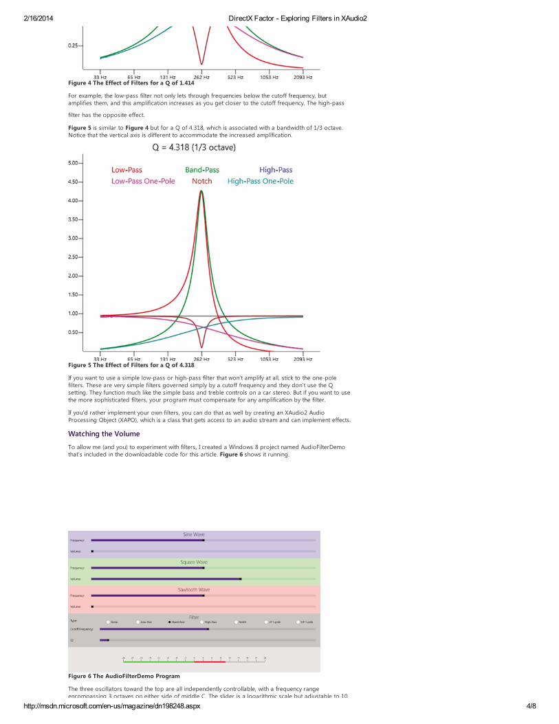
Figure 5 is similar to Figure 4 but for a Q of 4318 which is associated with a bandwidth of 13 octaveNotice that the vertical axis is different to accommodate the increased amplification
Figure 5 The Effect of Filters for a Q of 4318
If you want to use a simple low-pass or high-pass filter that wonrsquot amplify at all stick to the one-polefilters These are very simple filters governed simply by a cutoff frequency and they donrsquot use the Qsetting They function much like the simple bass and treble controls on a car stereo But if you want to usethe more sophisticated filters your program must compensate for any amplification by the filter
If yoursquod rather implement your own filters you can do that as well by creating an XAudio2 AudioProcessing Object (XAPO) which is a class that gets access to an audio stream and can implement effects
Watching the Volume
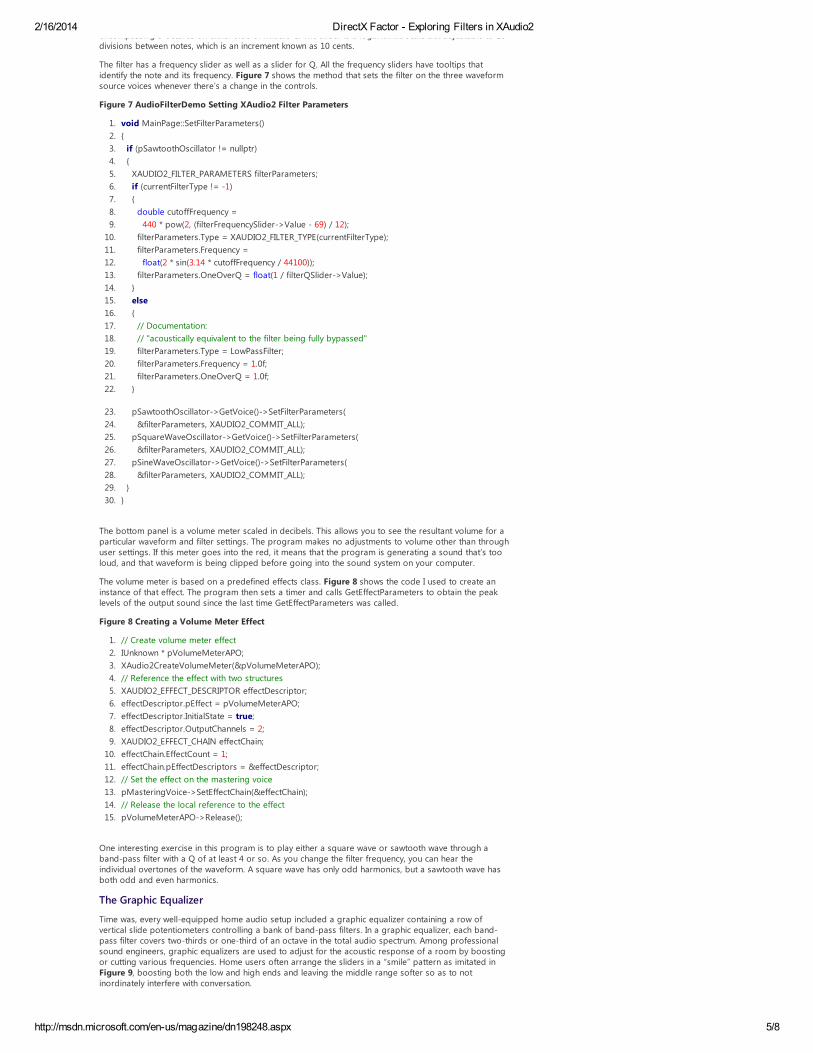
To allow me (and you) to experiment with filters I created a Windows 8 project named AudioFilterDemothatrsquos included in the downloadable code for this article Figure 6 shows it running
Figure 6 The AudioFilterDemo Program
The three oscillators toward the top are all independently controllable with a frequency rangeencompassing 3 octaves on either side of middle C The slider is a logarithmic scale but adjustable to 10
2162014 DirectX Factor - Exploring Filters in XAudio2
httpmsdnmicrosoftcomen-usmagazinedn198248aspx 58
encompassing 3 octaves on either side of middle C The slider is a logarithmic scale but adjustable to 10divisions between notes which is an increment known as 10 cents
The filter has a frequency slider as well as a slider for Q All the frequency sliders have tooltips thatidentify the note and its frequency Figure 7 shows the method that sets the filter on the three waveformsource voices whenever therersquos a change in the controls
Figure 7 AudioFilterDemo Setting XAudio2 Filter Parameters
1 void MainPageSetFilterParameters()
2
3 if (pSawtoothOscillator = nullptr)
4
5 XAUDIO2_FILTER_PARAMETERS filterParameters
6 if (currentFilterType = -1)
7
8 double cutoffFrequency =
9 440 pow(2 (filterFrequencySlider-gtValue - 69) 12)
10 filterParametersType = XAUDIO2_FILTER_TYPE(currentFilterType)
11 filterParametersFrequency =
12 float(2 sin(314 cutoffFrequency 44100))
13 filterParametersOneOverQ = float(1 filterQSlider-gtValue)
14
15 else
16
17 Documentation
18 acoustically equivalent to the filter being fully bypassed
19 filterParametersType = LowPassFilter
20 filterParametersFrequency = 10f
21 filterParametersOneOverQ = 10f
22
23 pSawtoothOscillator-gtGetVoice()-gtSetFilterParameters(
24 ampfilterParameters XAUDIO2_COMMIT_ALL)
25 pSquareWaveOscillator-gtGetVoice()-gtSetFilterParameters(
26 ampfilterParameters XAUDIO2_COMMIT_ALL)
27 pSineWaveOscillator-gtGetVoice()-gtSetFilterParameters(
28 ampfilterParameters XAUDIO2_COMMIT_ALL)
29
30
The bottom panel is a volume meter scaled in decibels This allows you to see the resultant volume for aparticular waveform and filter settings The program makes no adjustments to volume other than throughuser settings If this meter goes into the red it means that the program is generating a sound thatrsquos tooloud and that waveform is being clipped before going into the sound system on your computer
The volume meter is based on a predefined effects class Figure 8 shows the code I used to create aninstance of that effect The program then sets a timer and calls GetEffectParameters to obtain the peaklevels of the output sound since the last time GetEffectParameters was called
Figure 8 Creating a Volume Meter Effect
1 Create volume meter effect
2 IUnknown pVolumeMeterAPO
3 XAudio2CreateVolumeMeter(amppVolumeMeterAPO)
4 Reference the effect with two structures
5 XAUDIO2_EFFECT_DESCRIPTOR effectDescriptor
6 effectDescriptorpEffect = pVolumeMeterAPO
7 effectDescriptorInitialState = true
8 effectDescriptorOutputChannels = 2
9 XAUDIO2_EFFECT_CHAIN effectChain
10 effectChainEffectCount = 1
11 effectChainpEffectDescriptors = ampeffectDescriptor
12 Set the effect on the mastering voice
13 pMasteringVoice-gtSetEffectChain(ampeffectChain)
14 Release the local reference to the effect
15 pVolumeMeterAPO-gtRelease()
One interesting exercise in this program is to play either a square wave or sawtooth wave through aband-pass filter with a Q of at least 4 or so As you change the filter frequency you can hear theindividual overtones of the waveform A square wave has only odd harmonics but a sawtooth wave hasboth odd and even harmonics
The Graphic Equalizer
Time was every well-equipped home audio setup included a graphic equalizer containing a row ofvertical slide potentiometers controlling a bank of band-pass filters In a graphic equalizer each band-pass filter covers two-thirds or one-third of an octave in the total audio spectrum Among professionalsound engineers graphic equalizers are used to adjust for the acoustic response of a room by boostingor cutting various frequencies Home users often arrange the sliders in a ldquosmilerdquo pattern as imitated inFigure 9 boosting both the low and high ends and leaving the middle range softer so as to notinordinately interfere with conversation
2162014 DirectX Factor - Exploring Filters in XAudio2
httpmsdnmicrosoftcomen-usmagazinedn198248aspx 68
Figure 9 The GraphicEqualizer Program
The GraphicEqualizer program allows you to load an MP3 or WMA file from your Windows 8 MusicLibrary and play it through a 13-octave graphic equalizer The program contains 26 vertical sliders eachof which is associated with a band-pass filter As you can see each slider is labeled with the centerfrequency for that band In theory each center frequency should be the cube root of 2 (or about 126)higher than the previous filter but lots of rounding is employed to keep the numbers sensible Based ona photograph of a 13 graphic equalizer I found on Wikipedia I labeled the 26 sliders starting with 20 Hz25 315 40 and up through 63 KHz stopping short of the 7350 Hz limit for a 44100 Hz sampling rate
Most graphic equalizers have a separate band of potentiometers for left and right channels but Idecided to forgo that amenity
Yoursquove seen how a single filter can be applied to a particular IXAudio2SourceVoice instance but theGraphicEqualizer program needs to apply 26 filters to a source voice This is accomplished by creating 26instances of IXAudio2SubmixVoice corresponding to these filters (plus a couple more) and creatingwhatrsquos called in XAudio2 an ldquoaudio processing graphrdquo as shown in Figure 10 Each box is an instance ofone of the three interfaces that derive from IXAudio2Voice and the box identifies the variable name usedin the GraphicEqualizer program
Figure 10 The Audio Processing Graph Used in the GraphicEqualizer Program
An IXAudio2SubmixVoice instance canrsquot generate sound on its own That privilege is reserved for sourcevoices But it can get input from a source voice (or another submix voice) apply a volume filter or effectand pass the result on to one or more submix voices or to the mastering voice
At the top of Figure 10 is the source voice that generates the music from a music file At the bottom is themastering voice that sends the result out to the computerrsquos sound hardware In between are all thesubmix voices
2162014 DirectX Factor - Exploring Filters in XAudio2
httpmsdnmicrosoftcomen-usmagazinedn198248aspx 78
Sign in to Leave a Comment
Share this content
submix voices
Itrsquos a push model Whenever you create a source voice or submix voice you can indicate the destinationvoice (or voices) you want to receive the output of that voice Later on you can change the destination ofthat output with a call to SetOutputVoices If you specify NULL in either case the output goes to themastering voice
You indicate where you want the output of a voice to go with a pointer to an XAUDIO2_VOICE_SENDSstructure which contains two fields
SendCount of type unsigned integer
pSends which is a pointer to zero or more XAUDIO2_VOICE_DESCRIPTOR structures
The SendCount indicates the number of XAUDIO2_VOICE_DESCRIPTOR structures pointed to by pSends Itcan be zero to indicate that the voice doesnrsquot go anywhere The XAUDIO2_VOICE_DESCRIPTOR structurealso has two fields
Flags which can be 0 or XAUDIO2_SEND_USEFILTER
pOutputVoice of type IXAudio2Voice
The two IXAudio2SubmixVoice instances that feed into the bank of 26 submix voices and the one thatconsolidates the output from those 26 voices arenrsquot strictly needed to build the graphic equalizer butthey simplify the structure of the program Whenever the program creates a new source voicemdashwhich
happens whenever the user loads in a new music filemdashit just needs to direct the source voicersquos output tothe pSourceVoiceOutput instance
The program also has a CheckBox button to bypass the equalizer To disconnect the equalizer from theaudio processing graph all thatrsquos necessary is to call SetOutputVoices on the pSourceVoiceOutput with aNULL pointer indicating it should go to the mastering voice Restoring the equalizer involves a few lines ofcode to restore output from pSourceVoiceOutput to pEqualizerInput
There are a couple of ways to define the filters that comprise a graphic equalizer One approach is foreach slider to change the Q of that filtermdashin effect making the filter more restrictive as you increase theslider But I decided to keep the Q factor of each filter constant at a 13-octave bandwidth or 4318 anduse the slider to vary the volume of that submix voice Graphic equalizers usually allow switching the bankof sliders between a plusmn6 dB range and a plusmn12 dB range but I decided on a plusmn24 dB range for moreextreme effects
When an equalizer slider is in its center position the corresponding submix voice has a default volume of1 Normally that would mean that a sound just passes through the submix voice unaltered Howeverapplying a filter with a Q of 4318 in a submix voice causes the amplitude to increase by a factor of 4318at the center frequency To compensate for that the program sets the volume of the submix voicepEqualizerOutput to 1 divided by Q
With all the sliders set in their center positions clicking the CheckBox to switch the equalizer in and out ofthe audio graph causes no change in volume The sound does change a littlemdashundoubtedly resultingfrom the way the various band-pass filters overlapmdashbut the overall volume does not
The equalizer sliders have their Minimum properties set to -24 and Maximum set to 24 corresponding tothe gain in decibels When the slider value changes the volume for the corresponding submix voice is setin the ValueChanged event handler like so
1 Slider^ slider = dynamic_castltSlider^gt(sender)
2 int bandIndex = (int)slider-gtTag
3 float amplitude = float(pow(10 (args-gtNewValue 20)))
4 pEqualizerBands[bandIndex]-gtSetVolume(amplitude 0)
That amplitude calculation is an inverse of the decibel calculation shown earlier The resultant amplituderanges from about 006 (at -24 dB) to about 16 (at 24 dB) If you keep in mind that each change of 6 dB isa halving or doubling of the center amplitude of 1 these ranges make sense But if you crank up all thesliders to their maximum settings the overall amplitude increases by a factor of 16 and the result is likelyto be clipped and distorted
In other words the program implicitly assumes that the user maintains a balanced approach to life andwill reduce some sliders while increasing others
Charles Petzold is a longtime contributor to MSDN Magazine and the author of ldquoProgramming Windows 6theditionrdquo (OrsquoReilly Media 2012) a book about writing applications for Windows 8 His Web site ischarlespetzoldcom
Thanks to the following technical expert for reviewing this article Richard Fricks (Microsoft)
Rate
Comments (0)
2162014 DirectX Factor - Exploring Filters in XAudio2
httpmsdnmicrosoftcomen-usmagazinedn198248aspx 88
copy 2014 Microsoft All rights reserved Terms of Use | Trademarks | Privacy Statement | Site Feedback

2162014 DirectX Factor - Exploring Filters in XAudio2
httpmsdnmicrosoftcomen-usmagazinedn198248aspx 28
Figure 2 A Waveform in Time Domain (Top) and Frequency Domain (Bottom)
With some Fourier analysis we can separate this waveform into its constituent sine curves and representit in a somewhat different manner as shown on the bottom in Figure 2 This graph shows the relativeamplitudes of these constituent sine curves arranged by frequency In signal-processing lingo Figure 2shows the equivalence of the time-domain representation of a waveform on the top and the frequency-domain representation on the bottom
In real life a representation of a sound in its frequency domain would encompass the entire audiospectrum from 20 Hz to 20000 Hz and constantly change over the course of time
Filter Basics
The frequency-domain representation allows us to think of sound as a collection of sine waves of variousfrequencies and thatrsquos often useful in understanding audio processing
A very common type of audio processing involves amplifying or attenuating certain ranges of frequenciesin the audio spectrum thus altering the harmonic composition of the sound This is a tool known as afilter In analog signal processing filters are circuits in digital signal processing theyrsquore algorithms
The most common filter types are called low-pass high-pass and band-pass the terms refer to thefrequencies the filters let through The low-pass filter emphasizes lower frequencies by attenuating higherfrequencies Similarly the high-pass filter attenuates lower frequencies Both the low-pass and high-passfilters are defined by a particular cutoff frequency that indicates where the attenuation begins The band-pass filter doesnrsquot have a cutoff frequency but a center frequency serves a similar purpose Frequenciesoutside of a range around that center frequency are attenuated
Most filters canrsquot simply block all sine waves above or below a particular frequency Instead a sine wavewith a particular frequency is attenuated based on its distance from the cutoff or center frequency with aroll-off effect The slope of this roll-off is governed by a property of the filter known as Q which standsfor quality A filter with a higher Q has a steeper roll-off
The Q factor is easiest to interpret with a band-pass filter Figure 3 shows the effect of a band-pass filterapplied to a range of frequencies The center frequency is marked at f0 and two other frequencies aremarked f1 and f2 where the band-pass filter attenuates the amplitude to 707 percent of the f0 amplitude
Figure 3 Bandwidth in a Band-Pass Filter
Why 707 percent The power of a waveform is calculated as the square of the waveformrsquos amplitude and
f1 and f2 indicate the frequencies where the waveform has been attenuated to half its original powerBecause power is amplitude squared the amplitude at those points is the square root of 12 or 0707
Q is calculated by dividing the center frequency by the difference between the two half-powerfrequencies
Q = f0 (f2 ndash f1)
However the difference between f2 and f0 is not the same as the difference between f0 and f1 Insteadthe ratios are the same f2 f0 equals f0 f1 If f2 is double f1 thatrsquos an octave and itrsquos fairly easy tocalculate that Q equals the square root of 2 or approximately 1414
The ratio between f2 and f1 is known as the filterrsquos bandwidth and is often specified in octaves For a
2162014 DirectX Factor - Exploring Filters in XAudio2
httpmsdnmicrosoftcomen-usmagazinedn198248aspx 38
The ratio between f2 and f1 is known as the filterrsquos bandwidth and is often specified in octaves For abandwidth B in octaves you can calculate Q like so
As the bandwidth decreases Q increases and the roll-off is steeper
I said that f2 and f1 are the frequencies that the filter attenuates to half the power of f0 Half the power isalso known as -3 decibels The decibel is a logarithmic scale roughly approximating the humanperception of loudness The difference in decibels between two power levels P1 and P0 is
db = 10middotlog10(P1P0)
If P1 is half P0 the base-10 logarithm of 05 is -0301 and 10 times that is approximately -3 When dealingwith amplitudes decibels are calculated as
db = 20middotlog10(A1A0)
The base-10 logarithm of 0707 is -015 and 20 times that is also -3
Every doubling of the amplitude corresponds to an increase of 6 decibels which is why the 16-bitsampling rate of audio CDs is sometimes said to have a dynamic range of 96 decibels
Applying a Filter
If yoursquore using XAudio2 in a Windows 8 program to generate sounds or modify the sounds of existingmusic files applying a filter to those sounds is as simple as initializing three fields of anXAUDIO2_FILTER_PARAMETERS structure and calling a method named SetFilterParameters
As yoursquove seen in recent installments of this column a program creates one or more instances ofIXAudio2SourceVoice to define the waveforms themselves and a single instance of IXAudio2-MasteringVoice to effectively combine all the source voices into a single audio stream Later in this articleyoursquoll also see how to create instances of IXAudio2SubmixVoice to control the processing and mixing ofsounds on their way to the mastering voice Both source voices and submix voices support theSetFilterParameters method but only if the voices are created with the XAUDIO2_VOICE_USEFILTER flag
A call to SetFilterParameters requires a pointer to an XAUDIO2_FILTER_PARAMETERS structure which hasthree fields
Type set to one of the members of XAUDIO2_FILTER_TYPE enumeration which includes members for low-pass high-pass and band-pass filters as well as a notch (or band-reject) filter and single-pole low-passand high-pass filters which (as yoursquoll see shortly) are simpler filters
Frequency set to 2middotsin(πmiddotf0fs) where f0 is the cutoff frequency and fs is the sampling frequency where f0is not greater than 16 fs which means that the value set to the field is no greater than 1
OneOverQ 1 divided by the desired Q factor greater than zero and no greater than 15 Thus Q cannotbe less than 23 which corresponds to a bandwidth of 2 octaves
I havenrsquot yet shown you graphs similar to Figure 3 that illustrate how the low-pass and high-pass filtersattenuate frequencies Sometimes such graphs simply show a roll-off effect and thus can be dangerouslydeceptive if the actual filter doesnrsquot quite work like that Such is the case with XAudio2 filters For the low-pass high-pass band-pass and notch filters XAudio2 implements a type of digital filter known as abiquad which involves a fairly simple algorithm but does not create a simple roll-off effect for low-passand high-pass filters (If yoursquore interested in the algorithm follow the links in the Wikipedia article onldquoDigital biquad filterrdquo at bitlyYoeeq1)
Biquad filters tend to resonate at the center frequency of a band-pass filter and near the cutofffrequencies of the low-pass and high-pass filters This means that the filter not only attenuates somefrequencies but amplifies others To use these filters intelligently you must be aware of this effectFortunately this amplification is fairly easy to predict For the band-pass filter the amplitude of a sinewave at the center frequency is increased by a factor equal to Q For the low-pass and high-pass filtersthe maximum amplification near the cutoff frequency is equal to Q for higher values of Q but somewhatgreater than Q for lower values
Figure 4 shows the effects of all the XAudio2 filter types set for a frequency of 2616 Hz (middle C) and aQ of 1414 The horizontal axis is logarithmic with a range of 3 octaves above and below middle C Thevertical axis shows the resultant amplitude for sine curves at those frequencies The horizontal black lineat an amplitude of 1 is for no filter All the other lines are identified with different colors
2162014 DirectX Factor - Exploring Filters in XAudio2
httpmsdnmicrosoftcomen-usmagazinedn198248aspx 48
Figure 4 The Effect of Filters for a Q of 1414
For example the low-pass filter not only lets through frequencies below the cutoff frequency butamplifies them and this amplification increases as you get closer to the cutoff frequency The high-pass
filter has the opposite effect
Figure 5 is similar to Figure 4 but for a Q of 4318 which is associated with a bandwidth of 13 octaveNotice that the vertical axis is different to accommodate the increased amplification
Figure 5 The Effect of Filters for a Q of 4318
If you want to use a simple low-pass or high-pass filter that wonrsquot amplify at all stick to the one-polefilters These are very simple filters governed simply by a cutoff frequency and they donrsquot use the Qsetting They function much like the simple bass and treble controls on a car stereo But if you want to usethe more sophisticated filters your program must compensate for any amplification by the filter
If yoursquod rather implement your own filters you can do that as well by creating an XAudio2 AudioProcessing Object (XAPO) which is a class that gets access to an audio stream and can implement effects
Watching the Volume
To allow me (and you) to experiment with filters I created a Windows 8 project named AudioFilterDemothatrsquos included in the downloadable code for this article Figure 6 shows it running
Figure 6 The AudioFilterDemo Program
The three oscillators toward the top are all independently controllable with a frequency rangeencompassing 3 octaves on either side of middle C The slider is a logarithmic scale but adjustable to 10
2162014 DirectX Factor - Exploring Filters in XAudio2
httpmsdnmicrosoftcomen-usmagazinedn198248aspx 58
encompassing 3 octaves on either side of middle C The slider is a logarithmic scale but adjustable to 10divisions between notes which is an increment known as 10 cents
The filter has a frequency slider as well as a slider for Q All the frequency sliders have tooltips thatidentify the note and its frequency Figure 7 shows the method that sets the filter on the three waveformsource voices whenever therersquos a change in the controls
Figure 7 AudioFilterDemo Setting XAudio2 Filter Parameters
1 void MainPageSetFilterParameters()
2
3 if (pSawtoothOscillator = nullptr)
4
5 XAUDIO2_FILTER_PARAMETERS filterParameters
6 if (currentFilterType = -1)
7
8 double cutoffFrequency =
9 440 pow(2 (filterFrequencySlider-gtValue - 69) 12)
10 filterParametersType = XAUDIO2_FILTER_TYPE(currentFilterType)
11 filterParametersFrequency =
12 float(2 sin(314 cutoffFrequency 44100))
13 filterParametersOneOverQ = float(1 filterQSlider-gtValue)
14
15 else
16
17 Documentation
18 acoustically equivalent to the filter being fully bypassed
19 filterParametersType = LowPassFilter
20 filterParametersFrequency = 10f
21 filterParametersOneOverQ = 10f
22
23 pSawtoothOscillator-gtGetVoice()-gtSetFilterParameters(
24 ampfilterParameters XAUDIO2_COMMIT_ALL)
25 pSquareWaveOscillator-gtGetVoice()-gtSetFilterParameters(
26 ampfilterParameters XAUDIO2_COMMIT_ALL)
27 pSineWaveOscillator-gtGetVoice()-gtSetFilterParameters(
28 ampfilterParameters XAUDIO2_COMMIT_ALL)
29
30
The bottom panel is a volume meter scaled in decibels This allows you to see the resultant volume for aparticular waveform and filter settings The program makes no adjustments to volume other than throughuser settings If this meter goes into the red it means that the program is generating a sound thatrsquos tooloud and that waveform is being clipped before going into the sound system on your computer
The volume meter is based on a predefined effects class Figure 8 shows the code I used to create aninstance of that effect The program then sets a timer and calls GetEffectParameters to obtain the peaklevels of the output sound since the last time GetEffectParameters was called
Figure 8 Creating a Volume Meter Effect
1 Create volume meter effect
2 IUnknown pVolumeMeterAPO
3 XAudio2CreateVolumeMeter(amppVolumeMeterAPO)
4 Reference the effect with two structures
5 XAUDIO2_EFFECT_DESCRIPTOR effectDescriptor
6 effectDescriptorpEffect = pVolumeMeterAPO
7 effectDescriptorInitialState = true
8 effectDescriptorOutputChannels = 2
9 XAUDIO2_EFFECT_CHAIN effectChain
10 effectChainEffectCount = 1
11 effectChainpEffectDescriptors = ampeffectDescriptor
12 Set the effect on the mastering voice
13 pMasteringVoice-gtSetEffectChain(ampeffectChain)
14 Release the local reference to the effect
15 pVolumeMeterAPO-gtRelease()
One interesting exercise in this program is to play either a square wave or sawtooth wave through aband-pass filter with a Q of at least 4 or so As you change the filter frequency you can hear theindividual overtones of the waveform A square wave has only odd harmonics but a sawtooth wave hasboth odd and even harmonics
The Graphic Equalizer
Time was every well-equipped home audio setup included a graphic equalizer containing a row ofvertical slide potentiometers controlling a bank of band-pass filters In a graphic equalizer each band-pass filter covers two-thirds or one-third of an octave in the total audio spectrum Among professionalsound engineers graphic equalizers are used to adjust for the acoustic response of a room by boostingor cutting various frequencies Home users often arrange the sliders in a ldquosmilerdquo pattern as imitated inFigure 9 boosting both the low and high ends and leaving the middle range softer so as to notinordinately interfere with conversation
2162014 DirectX Factor - Exploring Filters in XAudio2
httpmsdnmicrosoftcomen-usmagazinedn198248aspx 68
Figure 9 The GraphicEqualizer Program
The GraphicEqualizer program allows you to load an MP3 or WMA file from your Windows 8 MusicLibrary and play it through a 13-octave graphic equalizer The program contains 26 vertical sliders eachof which is associated with a band-pass filter As you can see each slider is labeled with the centerfrequency for that band In theory each center frequency should be the cube root of 2 (or about 126)higher than the previous filter but lots of rounding is employed to keep the numbers sensible Based ona photograph of a 13 graphic equalizer I found on Wikipedia I labeled the 26 sliders starting with 20 Hz25 315 40 and up through 63 KHz stopping short of the 7350 Hz limit for a 44100 Hz sampling rate
Most graphic equalizers have a separate band of potentiometers for left and right channels but Idecided to forgo that amenity
Yoursquove seen how a single filter can be applied to a particular IXAudio2SourceVoice instance but theGraphicEqualizer program needs to apply 26 filters to a source voice This is accomplished by creating 26instances of IXAudio2SubmixVoice corresponding to these filters (plus a couple more) and creatingwhatrsquos called in XAudio2 an ldquoaudio processing graphrdquo as shown in Figure 10 Each box is an instance ofone of the three interfaces that derive from IXAudio2Voice and the box identifies the variable name usedin the GraphicEqualizer program
Figure 10 The Audio Processing Graph Used in the GraphicEqualizer Program
An IXAudio2SubmixVoice instance canrsquot generate sound on its own That privilege is reserved for sourcevoices But it can get input from a source voice (or another submix voice) apply a volume filter or effectand pass the result on to one or more submix voices or to the mastering voice
At the top of Figure 10 is the source voice that generates the music from a music file At the bottom is themastering voice that sends the result out to the computerrsquos sound hardware In between are all thesubmix voices
2162014 DirectX Factor - Exploring Filters in XAudio2
httpmsdnmicrosoftcomen-usmagazinedn198248aspx 78
Sign in to Leave a Comment
Share this content
submix voices
Itrsquos a push model Whenever you create a source voice or submix voice you can indicate the destinationvoice (or voices) you want to receive the output of that voice Later on you can change the destination ofthat output with a call to SetOutputVoices If you specify NULL in either case the output goes to themastering voice
You indicate where you want the output of a voice to go with a pointer to an XAUDIO2_VOICE_SENDSstructure which contains two fields
SendCount of type unsigned integer
pSends which is a pointer to zero or more XAUDIO2_VOICE_DESCRIPTOR structures
The SendCount indicates the number of XAUDIO2_VOICE_DESCRIPTOR structures pointed to by pSends Itcan be zero to indicate that the voice doesnrsquot go anywhere The XAUDIO2_VOICE_DESCRIPTOR structurealso has two fields
Flags which can be 0 or XAUDIO2_SEND_USEFILTER
pOutputVoice of type IXAudio2Voice
The two IXAudio2SubmixVoice instances that feed into the bank of 26 submix voices and the one thatconsolidates the output from those 26 voices arenrsquot strictly needed to build the graphic equalizer butthey simplify the structure of the program Whenever the program creates a new source voicemdashwhich
happens whenever the user loads in a new music filemdashit just needs to direct the source voicersquos output tothe pSourceVoiceOutput instance
The program also has a CheckBox button to bypass the equalizer To disconnect the equalizer from theaudio processing graph all thatrsquos necessary is to call SetOutputVoices on the pSourceVoiceOutput with aNULL pointer indicating it should go to the mastering voice Restoring the equalizer involves a few lines ofcode to restore output from pSourceVoiceOutput to pEqualizerInput
There are a couple of ways to define the filters that comprise a graphic equalizer One approach is foreach slider to change the Q of that filtermdashin effect making the filter more restrictive as you increase theslider But I decided to keep the Q factor of each filter constant at a 13-octave bandwidth or 4318 anduse the slider to vary the volume of that submix voice Graphic equalizers usually allow switching the bankof sliders between a plusmn6 dB range and a plusmn12 dB range but I decided on a plusmn24 dB range for moreextreme effects
When an equalizer slider is in its center position the corresponding submix voice has a default volume of1 Normally that would mean that a sound just passes through the submix voice unaltered Howeverapplying a filter with a Q of 4318 in a submix voice causes the amplitude to increase by a factor of 4318at the center frequency To compensate for that the program sets the volume of the submix voicepEqualizerOutput to 1 divided by Q
With all the sliders set in their center positions clicking the CheckBox to switch the equalizer in and out ofthe audio graph causes no change in volume The sound does change a littlemdashundoubtedly resultingfrom the way the various band-pass filters overlapmdashbut the overall volume does not
The equalizer sliders have their Minimum properties set to -24 and Maximum set to 24 corresponding tothe gain in decibels When the slider value changes the volume for the corresponding submix voice is setin the ValueChanged event handler like so
1 Slider^ slider = dynamic_castltSlider^gt(sender)
2 int bandIndex = (int)slider-gtTag
3 float amplitude = float(pow(10 (args-gtNewValue 20)))
4 pEqualizerBands[bandIndex]-gtSetVolume(amplitude 0)
That amplitude calculation is an inverse of the decibel calculation shown earlier The resultant amplituderanges from about 006 (at -24 dB) to about 16 (at 24 dB) If you keep in mind that each change of 6 dB isa halving or doubling of the center amplitude of 1 these ranges make sense But if you crank up all thesliders to their maximum settings the overall amplitude increases by a factor of 16 and the result is likelyto be clipped and distorted
In other words the program implicitly assumes that the user maintains a balanced approach to life andwill reduce some sliders while increasing others
Charles Petzold is a longtime contributor to MSDN Magazine and the author of ldquoProgramming Windows 6theditionrdquo (OrsquoReilly Media 2012) a book about writing applications for Windows 8 His Web site ischarlespetzoldcom
Thanks to the following technical expert for reviewing this article Richard Fricks (Microsoft)
Rate
Comments (0)
2162014 DirectX Factor - Exploring Filters in XAudio2
httpmsdnmicrosoftcomen-usmagazinedn198248aspx 88
copy 2014 Microsoft All rights reserved Terms of Use | Trademarks | Privacy Statement | Site Feedback

2162014 DirectX Factor - Exploring Filters in XAudio2
httpmsdnmicrosoftcomen-usmagazinedn198248aspx 38
The ratio between f2 and f1 is known as the filterrsquos bandwidth and is often specified in octaves For abandwidth B in octaves you can calculate Q like so
As the bandwidth decreases Q increases and the roll-off is steeper
I said that f2 and f1 are the frequencies that the filter attenuates to half the power of f0 Half the power isalso known as -3 decibels The decibel is a logarithmic scale roughly approximating the humanperception of loudness The difference in decibels between two power levels P1 and P0 is
db = 10middotlog10(P1P0)
If P1 is half P0 the base-10 logarithm of 05 is -0301 and 10 times that is approximately -3 When dealingwith amplitudes decibels are calculated as
db = 20middotlog10(A1A0)
The base-10 logarithm of 0707 is -015 and 20 times that is also -3
Every doubling of the amplitude corresponds to an increase of 6 decibels which is why the 16-bitsampling rate of audio CDs is sometimes said to have a dynamic range of 96 decibels
Applying a Filter
If yoursquore using XAudio2 in a Windows 8 program to generate sounds or modify the sounds of existingmusic files applying a filter to those sounds is as simple as initializing three fields of anXAUDIO2_FILTER_PARAMETERS structure and calling a method named SetFilterParameters
As yoursquove seen in recent installments of this column a program creates one or more instances ofIXAudio2SourceVoice to define the waveforms themselves and a single instance of IXAudio2-MasteringVoice to effectively combine all the source voices into a single audio stream Later in this articleyoursquoll also see how to create instances of IXAudio2SubmixVoice to control the processing and mixing ofsounds on their way to the mastering voice Both source voices and submix voices support theSetFilterParameters method but only if the voices are created with the XAUDIO2_VOICE_USEFILTER flag
A call to SetFilterParameters requires a pointer to an XAUDIO2_FILTER_PARAMETERS structure which hasthree fields
Type set to one of the members of XAUDIO2_FILTER_TYPE enumeration which includes members for low-pass high-pass and band-pass filters as well as a notch (or band-reject) filter and single-pole low-passand high-pass filters which (as yoursquoll see shortly) are simpler filters
Frequency set to 2middotsin(πmiddotf0fs) where f0 is the cutoff frequency and fs is the sampling frequency where f0is not greater than 16 fs which means that the value set to the field is no greater than 1
OneOverQ 1 divided by the desired Q factor greater than zero and no greater than 15 Thus Q cannotbe less than 23 which corresponds to a bandwidth of 2 octaves
I havenrsquot yet shown you graphs similar to Figure 3 that illustrate how the low-pass and high-pass filtersattenuate frequencies Sometimes such graphs simply show a roll-off effect and thus can be dangerouslydeceptive if the actual filter doesnrsquot quite work like that Such is the case with XAudio2 filters For the low-pass high-pass band-pass and notch filters XAudio2 implements a type of digital filter known as abiquad which involves a fairly simple algorithm but does not create a simple roll-off effect for low-passand high-pass filters (If yoursquore interested in the algorithm follow the links in the Wikipedia article onldquoDigital biquad filterrdquo at bitlyYoeeq1)
Biquad filters tend to resonate at the center frequency of a band-pass filter and near the cutofffrequencies of the low-pass and high-pass filters This means that the filter not only attenuates somefrequencies but amplifies others To use these filters intelligently you must be aware of this effectFortunately this amplification is fairly easy to predict For the band-pass filter the amplitude of a sinewave at the center frequency is increased by a factor equal to Q For the low-pass and high-pass filtersthe maximum amplification near the cutoff frequency is equal to Q for higher values of Q but somewhatgreater than Q for lower values
Figure 4 shows the effects of all the XAudio2 filter types set for a frequency of 2616 Hz (middle C) and aQ of 1414 The horizontal axis is logarithmic with a range of 3 octaves above and below middle C Thevertical axis shows the resultant amplitude for sine curves at those frequencies The horizontal black lineat an amplitude of 1 is for no filter All the other lines are identified with different colors
2162014 DirectX Factor - Exploring Filters in XAudio2
httpmsdnmicrosoftcomen-usmagazinedn198248aspx 48
Figure 4 The Effect of Filters for a Q of 1414
For example the low-pass filter not only lets through frequencies below the cutoff frequency butamplifies them and this amplification increases as you get closer to the cutoff frequency The high-pass
filter has the opposite effect
Figure 5 is similar to Figure 4 but for a Q of 4318 which is associated with a bandwidth of 13 octaveNotice that the vertical axis is different to accommodate the increased amplification
Figure 5 The Effect of Filters for a Q of 4318
If you want to use a simple low-pass or high-pass filter that wonrsquot amplify at all stick to the one-polefilters These are very simple filters governed simply by a cutoff frequency and they donrsquot use the Qsetting They function much like the simple bass and treble controls on a car stereo But if you want to usethe more sophisticated filters your program must compensate for any amplification by the filter
If yoursquod rather implement your own filters you can do that as well by creating an XAudio2 AudioProcessing Object (XAPO) which is a class that gets access to an audio stream and can implement effects
Watching the Volume
To allow me (and you) to experiment with filters I created a Windows 8 project named AudioFilterDemothatrsquos included in the downloadable code for this article Figure 6 shows it running
Figure 6 The AudioFilterDemo Program
The three oscillators toward the top are all independently controllable with a frequency rangeencompassing 3 octaves on either side of middle C The slider is a logarithmic scale but adjustable to 10
2162014 DirectX Factor - Exploring Filters in XAudio2
httpmsdnmicrosoftcomen-usmagazinedn198248aspx 58
encompassing 3 octaves on either side of middle C The slider is a logarithmic scale but adjustable to 10divisions between notes which is an increment known as 10 cents
The filter has a frequency slider as well as a slider for Q All the frequency sliders have tooltips thatidentify the note and its frequency Figure 7 shows the method that sets the filter on the three waveformsource voices whenever therersquos a change in the controls
Figure 7 AudioFilterDemo Setting XAudio2 Filter Parameters
1 void MainPageSetFilterParameters()
2
3 if (pSawtoothOscillator = nullptr)
4
5 XAUDIO2_FILTER_PARAMETERS filterParameters
6 if (currentFilterType = -1)
7
8 double cutoffFrequency =
9 440 pow(2 (filterFrequencySlider-gtValue - 69) 12)
10 filterParametersType = XAUDIO2_FILTER_TYPE(currentFilterType)
11 filterParametersFrequency =
12 float(2 sin(314 cutoffFrequency 44100))
13 filterParametersOneOverQ = float(1 filterQSlider-gtValue)
14
15 else
16
17 Documentation
18 acoustically equivalent to the filter being fully bypassed
19 filterParametersType = LowPassFilter
20 filterParametersFrequency = 10f
21 filterParametersOneOverQ = 10f
22
23 pSawtoothOscillator-gtGetVoice()-gtSetFilterParameters(
24 ampfilterParameters XAUDIO2_COMMIT_ALL)
25 pSquareWaveOscillator-gtGetVoice()-gtSetFilterParameters(
26 ampfilterParameters XAUDIO2_COMMIT_ALL)
27 pSineWaveOscillator-gtGetVoice()-gtSetFilterParameters(
28 ampfilterParameters XAUDIO2_COMMIT_ALL)
29
30
The bottom panel is a volume meter scaled in decibels This allows you to see the resultant volume for aparticular waveform and filter settings The program makes no adjustments to volume other than throughuser settings If this meter goes into the red it means that the program is generating a sound thatrsquos tooloud and that waveform is being clipped before going into the sound system on your computer
The volume meter is based on a predefined effects class Figure 8 shows the code I used to create aninstance of that effect The program then sets a timer and calls GetEffectParameters to obtain the peaklevels of the output sound since the last time GetEffectParameters was called
Figure 8 Creating a Volume Meter Effect
1 Create volume meter effect
2 IUnknown pVolumeMeterAPO
3 XAudio2CreateVolumeMeter(amppVolumeMeterAPO)
4 Reference the effect with two structures
5 XAUDIO2_EFFECT_DESCRIPTOR effectDescriptor
6 effectDescriptorpEffect = pVolumeMeterAPO
7 effectDescriptorInitialState = true
8 effectDescriptorOutputChannels = 2
9 XAUDIO2_EFFECT_CHAIN effectChain
10 effectChainEffectCount = 1
11 effectChainpEffectDescriptors = ampeffectDescriptor
12 Set the effect on the mastering voice
13 pMasteringVoice-gtSetEffectChain(ampeffectChain)
14 Release the local reference to the effect
15 pVolumeMeterAPO-gtRelease()
One interesting exercise in this program is to play either a square wave or sawtooth wave through aband-pass filter with a Q of at least 4 or so As you change the filter frequency you can hear theindividual overtones of the waveform A square wave has only odd harmonics but a sawtooth wave hasboth odd and even harmonics
The Graphic Equalizer
Time was every well-equipped home audio setup included a graphic equalizer containing a row ofvertical slide potentiometers controlling a bank of band-pass filters In a graphic equalizer each band-pass filter covers two-thirds or one-third of an octave in the total audio spectrum Among professionalsound engineers graphic equalizers are used to adjust for the acoustic response of a room by boostingor cutting various frequencies Home users often arrange the sliders in a ldquosmilerdquo pattern as imitated inFigure 9 boosting both the low and high ends and leaving the middle range softer so as to notinordinately interfere with conversation
2162014 DirectX Factor - Exploring Filters in XAudio2
httpmsdnmicrosoftcomen-usmagazinedn198248aspx 68
Figure 9 The GraphicEqualizer Program
The GraphicEqualizer program allows you to load an MP3 or WMA file from your Windows 8 MusicLibrary and play it through a 13-octave graphic equalizer The program contains 26 vertical sliders eachof which is associated with a band-pass filter As you can see each slider is labeled with the centerfrequency for that band In theory each center frequency should be the cube root of 2 (or about 126)higher than the previous filter but lots of rounding is employed to keep the numbers sensible Based ona photograph of a 13 graphic equalizer I found on Wikipedia I labeled the 26 sliders starting with 20 Hz25 315 40 and up through 63 KHz stopping short of the 7350 Hz limit for a 44100 Hz sampling rate
Most graphic equalizers have a separate band of potentiometers for left and right channels but Idecided to forgo that amenity
Yoursquove seen how a single filter can be applied to a particular IXAudio2SourceVoice instance but theGraphicEqualizer program needs to apply 26 filters to a source voice This is accomplished by creating 26instances of IXAudio2SubmixVoice corresponding to these filters (plus a couple more) and creatingwhatrsquos called in XAudio2 an ldquoaudio processing graphrdquo as shown in Figure 10 Each box is an instance ofone of the three interfaces that derive from IXAudio2Voice and the box identifies the variable name usedin the GraphicEqualizer program
Figure 10 The Audio Processing Graph Used in the GraphicEqualizer Program
An IXAudio2SubmixVoice instance canrsquot generate sound on its own That privilege is reserved for sourcevoices But it can get input from a source voice (or another submix voice) apply a volume filter or effectand pass the result on to one or more submix voices or to the mastering voice
At the top of Figure 10 is the source voice that generates the music from a music file At the bottom is themastering voice that sends the result out to the computerrsquos sound hardware In between are all thesubmix voices
2162014 DirectX Factor - Exploring Filters in XAudio2
httpmsdnmicrosoftcomen-usmagazinedn198248aspx 78
Sign in to Leave a Comment
Share this content
submix voices
Itrsquos a push model Whenever you create a source voice or submix voice you can indicate the destinationvoice (or voices) you want to receive the output of that voice Later on you can change the destination ofthat output with a call to SetOutputVoices If you specify NULL in either case the output goes to themastering voice
You indicate where you want the output of a voice to go with a pointer to an XAUDIO2_VOICE_SENDSstructure which contains two fields
SendCount of type unsigned integer
pSends which is a pointer to zero or more XAUDIO2_VOICE_DESCRIPTOR structures
The SendCount indicates the number of XAUDIO2_VOICE_DESCRIPTOR structures pointed to by pSends Itcan be zero to indicate that the voice doesnrsquot go anywhere The XAUDIO2_VOICE_DESCRIPTOR structurealso has two fields
Flags which can be 0 or XAUDIO2_SEND_USEFILTER
pOutputVoice of type IXAudio2Voice
The two IXAudio2SubmixVoice instances that feed into the bank of 26 submix voices and the one thatconsolidates the output from those 26 voices arenrsquot strictly needed to build the graphic equalizer butthey simplify the structure of the program Whenever the program creates a new source voicemdashwhich
happens whenever the user loads in a new music filemdashit just needs to direct the source voicersquos output tothe pSourceVoiceOutput instance
The program also has a CheckBox button to bypass the equalizer To disconnect the equalizer from theaudio processing graph all thatrsquos necessary is to call SetOutputVoices on the pSourceVoiceOutput with aNULL pointer indicating it should go to the mastering voice Restoring the equalizer involves a few lines ofcode to restore output from pSourceVoiceOutput to pEqualizerInput
There are a couple of ways to define the filters that comprise a graphic equalizer One approach is foreach slider to change the Q of that filtermdashin effect making the filter more restrictive as you increase theslider But I decided to keep the Q factor of each filter constant at a 13-octave bandwidth or 4318 anduse the slider to vary the volume of that submix voice Graphic equalizers usually allow switching the bankof sliders between a plusmn6 dB range and a plusmn12 dB range but I decided on a plusmn24 dB range for moreextreme effects
When an equalizer slider is in its center position the corresponding submix voice has a default volume of1 Normally that would mean that a sound just passes through the submix voice unaltered Howeverapplying a filter with a Q of 4318 in a submix voice causes the amplitude to increase by a factor of 4318at the center frequency To compensate for that the program sets the volume of the submix voicepEqualizerOutput to 1 divided by Q
With all the sliders set in their center positions clicking the CheckBox to switch the equalizer in and out ofthe audio graph causes no change in volume The sound does change a littlemdashundoubtedly resultingfrom the way the various band-pass filters overlapmdashbut the overall volume does not
The equalizer sliders have their Minimum properties set to -24 and Maximum set to 24 corresponding tothe gain in decibels When the slider value changes the volume for the corresponding submix voice is setin the ValueChanged event handler like so
1 Slider^ slider = dynamic_castltSlider^gt(sender)
2 int bandIndex = (int)slider-gtTag
3 float amplitude = float(pow(10 (args-gtNewValue 20)))
4 pEqualizerBands[bandIndex]-gtSetVolume(amplitude 0)
That amplitude calculation is an inverse of the decibel calculation shown earlier The resultant amplituderanges from about 006 (at -24 dB) to about 16 (at 24 dB) If you keep in mind that each change of 6 dB isa halving or doubling of the center amplitude of 1 these ranges make sense But if you crank up all thesliders to their maximum settings the overall amplitude increases by a factor of 16 and the result is likelyto be clipped and distorted
In other words the program implicitly assumes that the user maintains a balanced approach to life andwill reduce some sliders while increasing others
Charles Petzold is a longtime contributor to MSDN Magazine and the author of ldquoProgramming Windows 6theditionrdquo (OrsquoReilly Media 2012) a book about writing applications for Windows 8 His Web site ischarlespetzoldcom
Thanks to the following technical expert for reviewing this article Richard Fricks (Microsoft)
Rate
Comments (0)
2162014 DirectX Factor - Exploring Filters in XAudio2
httpmsdnmicrosoftcomen-usmagazinedn198248aspx 88
copy 2014 Microsoft All rights reserved Terms of Use | Trademarks | Privacy Statement | Site Feedback
2162014 DirectX Factor - Exploring Filters in XAudio2
httpmsdnmicrosoftcomen-usmagazinedn198248aspx 58
encompassing 3 octaves on either side of middle C The slider is a logarithmic scale but adjustable to 10divisions between notes which is an increment known as 10 cents
The filter has a frequency slider as well as a slider for Q All the frequency sliders have tooltips thatidentify the note and its frequency Figure 7 shows the method that sets the filter on the three waveformsource voices whenever therersquos a change in the controls
Figure 7 AudioFilterDemo Setting XAudio2 Filter Parameters
1 void MainPageSetFilterParameters()
2
3 if (pSawtoothOscillator = nullptr)
4
5 XAUDIO2_FILTER_PARAMETERS filterParameters
6 if (currentFilterType = -1)
7
8 double cutoffFrequency =
9 440 pow(2 (filterFrequencySlider-gtValue - 69) 12)
10 filterParametersType = XAUDIO2_FILTER_TYPE(currentFilterType)
11 filterParametersFrequency =
12 float(2 sin(314 cutoffFrequency 44100))
13 filterParametersOneOverQ = float(1 filterQSlider-gtValue)
14
15 else
16
17 Documentation
18 acoustically equivalent to the filter being fully bypassed
19 filterParametersType = LowPassFilter
20 filterParametersFrequency = 10f
21 filterParametersOneOverQ = 10f
22
23 pSawtoothOscillator-gtGetVoice()-gtSetFilterParameters(
24 ampfilterParameters XAUDIO2_COMMIT_ALL)
25 pSquareWaveOscillator-gtGetVoice()-gtSetFilterParameters(
26 ampfilterParameters XAUDIO2_COMMIT_ALL)
27 pSineWaveOscillator-gtGetVoice()-gtSetFilterParameters(
28 ampfilterParameters XAUDIO2_COMMIT_ALL)
29
30
The bottom panel is a volume meter scaled in decibels This allows you to see the resultant volume for aparticular waveform and filter settings The program makes no adjustments to volume other than throughuser settings If this meter goes into the red it means that the program is generating a sound thatrsquos tooloud and that waveform is being clipped before going into the sound system on your computer
The volume meter is based on a predefined effects class Figure 8 shows the code I used to create aninstance of that effect The program then sets a timer and calls GetEffectParameters to obtain the peaklevels of the output sound since the last time GetEffectParameters was called
Figure 8 Creating a Volume Meter Effect
1 Create volume meter effect
2 IUnknown pVolumeMeterAPO
3 XAudio2CreateVolumeMeter(amppVolumeMeterAPO)
4 Reference the effect with two structures
5 XAUDIO2_EFFECT_DESCRIPTOR effectDescriptor
6 effectDescriptorpEffect = pVolumeMeterAPO
7 effectDescriptorInitialState = true
8 effectDescriptorOutputChannels = 2
9 XAUDIO2_EFFECT_CHAIN effectChain
10 effectChainEffectCount = 1
11 effectChainpEffectDescriptors = ampeffectDescriptor
12 Set the effect on the mastering voice
13 pMasteringVoice-gtSetEffectChain(ampeffectChain)
14 Release the local reference to the effect
15 pVolumeMeterAPO-gtRelease()
One interesting exercise in this program is to play either a square wave or sawtooth wave through aband-pass filter with a Q of at least 4 or so As you change the filter frequency you can hear theindividual overtones of the waveform A square wave has only odd harmonics but a sawtooth wave hasboth odd and even harmonics
The Graphic Equalizer
Time was every well-equipped home audio setup included a graphic equalizer containing a row ofvertical slide potentiometers controlling a bank of band-pass filters In a graphic equalizer each band-pass filter covers two-thirds or one-third of an octave in the total audio spectrum Among professionalsound engineers graphic equalizers are used to adjust for the acoustic response of a room by boostingor cutting various frequencies Home users often arrange the sliders in a ldquosmilerdquo pattern as imitated inFigure 9 boosting both the low and high ends and leaving the middle range softer so as to notinordinately interfere with conversation
2162014 DirectX Factor - Exploring Filters in XAudio2
httpmsdnmicrosoftcomen-usmagazinedn198248aspx 68
Figure 9 The GraphicEqualizer Program
The GraphicEqualizer program allows you to load an MP3 or WMA file from your Windows 8 MusicLibrary and play it through a 13-octave graphic equalizer The program contains 26 vertical sliders eachof which is associated with a band-pass filter As you can see each slider is labeled with the centerfrequency for that band In theory each center frequency should be the cube root of 2 (or about 126)higher than the previous filter but lots of rounding is employed to keep the numbers sensible Based ona photograph of a 13 graphic equalizer I found on Wikipedia I labeled the 26 sliders starting with 20 Hz25 315 40 and up through 63 KHz stopping short of the 7350 Hz limit for a 44100 Hz sampling rate
Most graphic equalizers have a separate band of potentiometers for left and right channels but Idecided to forgo that amenity
Yoursquove seen how a single filter can be applied to a particular IXAudio2SourceVoice instance but theGraphicEqualizer program needs to apply 26 filters to a source voice This is accomplished by creating 26instances of IXAudio2SubmixVoice corresponding to these filters (plus a couple more) and creatingwhatrsquos called in XAudio2 an ldquoaudio processing graphrdquo as shown in Figure 10 Each box is an instance ofone of the three interfaces that derive from IXAudio2Voice and the box identifies the variable name usedin the GraphicEqualizer program
Figure 10 The Audio Processing Graph Used in the GraphicEqualizer Program
An IXAudio2SubmixVoice instance canrsquot generate sound on its own That privilege is reserved for sourcevoices But it can get input from a source voice (or another submix voice) apply a volume filter or effectand pass the result on to one or more submix voices or to the mastering voice
At the top of Figure 10 is the source voice that generates the music from a music file At the bottom is themastering voice that sends the result out to the computerrsquos sound hardware In between are all thesubmix voices
2162014 DirectX Factor - Exploring Filters in XAudio2
httpmsdnmicrosoftcomen-usmagazinedn198248aspx 78
Sign in to Leave a Comment
Share this content
submix voices
Itrsquos a push model Whenever you create a source voice or submix voice you can indicate the destinationvoice (or voices) you want to receive the output of that voice Later on you can change the destination ofthat output with a call to SetOutputVoices If you specify NULL in either case the output goes to themastering voice
You indicate where you want the output of a voice to go with a pointer to an XAUDIO2_VOICE_SENDSstructure which contains two fields
SendCount of type unsigned integer
pSends which is a pointer to zero or more XAUDIO2_VOICE_DESCRIPTOR structures
The SendCount indicates the number of XAUDIO2_VOICE_DESCRIPTOR structures pointed to by pSends Itcan be zero to indicate that the voice doesnrsquot go anywhere The XAUDIO2_VOICE_DESCRIPTOR structurealso has two fields
Flags which can be 0 or XAUDIO2_SEND_USEFILTER
pOutputVoice of type IXAudio2Voice
The two IXAudio2SubmixVoice instances that feed into the bank of 26 submix voices and the one thatconsolidates the output from those 26 voices arenrsquot strictly needed to build the graphic equalizer butthey simplify the structure of the program Whenever the program creates a new source voicemdashwhich
happens whenever the user loads in a new music filemdashit just needs to direct the source voicersquos output tothe pSourceVoiceOutput instance
The program also has a CheckBox button to bypass the equalizer To disconnect the equalizer from theaudio processing graph all thatrsquos necessary is to call SetOutputVoices on the pSourceVoiceOutput with aNULL pointer indicating it should go to the mastering voice Restoring the equalizer involves a few lines ofcode to restore output from pSourceVoiceOutput to pEqualizerInput
There are a couple of ways to define the filters that comprise a graphic equalizer One approach is foreach slider to change the Q of that filtermdashin effect making the filter more restrictive as you increase theslider But I decided to keep the Q factor of each filter constant at a 13-octave bandwidth or 4318 anduse the slider to vary the volume of that submix voice Graphic equalizers usually allow switching the bankof sliders between a plusmn6 dB range and a plusmn12 dB range but I decided on a plusmn24 dB range for moreextreme effects
When an equalizer slider is in its center position the corresponding submix voice has a default volume of1 Normally that would mean that a sound just passes through the submix voice unaltered Howeverapplying a filter with a Q of 4318 in a submix voice causes the amplitude to increase by a factor of 4318at the center frequency To compensate for that the program sets the volume of the submix voicepEqualizerOutput to 1 divided by Q
With all the sliders set in their center positions clicking the CheckBox to switch the equalizer in and out ofthe audio graph causes no change in volume The sound does change a littlemdashundoubtedly resultingfrom the way the various band-pass filters overlapmdashbut the overall volume does not
The equalizer sliders have their Minimum properties set to -24 and Maximum set to 24 corresponding tothe gain in decibels When the slider value changes the volume for the corresponding submix voice is setin the ValueChanged event handler like so
1 Slider^ slider = dynamic_castltSlider^gt(sender)
2 int bandIndex = (int)slider-gtTag
3 float amplitude = float(pow(10 (args-gtNewValue 20)))
4 pEqualizerBands[bandIndex]-gtSetVolume(amplitude 0)
That amplitude calculation is an inverse of the decibel calculation shown earlier The resultant amplituderanges from about 006 (at -24 dB) to about 16 (at 24 dB) If you keep in mind that each change of 6 dB isa halving or doubling of the center amplitude of 1 these ranges make sense But if you crank up all thesliders to their maximum settings the overall amplitude increases by a factor of 16 and the result is likelyto be clipped and distorted
In other words the program implicitly assumes that the user maintains a balanced approach to life andwill reduce some sliders while increasing others
Charles Petzold is a longtime contributor to MSDN Magazine and the author of ldquoProgramming Windows 6theditionrdquo (OrsquoReilly Media 2012) a book about writing applications for Windows 8 His Web site ischarlespetzoldcom
Thanks to the following technical expert for reviewing this article Richard Fricks (Microsoft)
Rate
Comments (0)
2162014 DirectX Factor - Exploring Filters in XAudio2
httpmsdnmicrosoftcomen-usmagazinedn198248aspx 88
copy 2014 Microsoft All rights reserved Terms of Use | Trademarks | Privacy Statement | Site Feedback

2162014 DirectX Factor - Exploring Filters in XAudio2
httpmsdnmicrosoftcomen-usmagazinedn198248aspx 88
copy 2014 Microsoft All rights reserved Terms of Use | Trademarks | Privacy Statement | Site Feedback