Embed Size (px)
Citation preview
DD
Director’s ReviewDec 1999
Tracker Integration and Installation
W. E. Cooper6 December 1999
DD
Director’s ReviewDec 1999
Introduction
A tracker integration and installation group has been formed within the past month.
Manpower for design work on tracker integration and installation has been assumed to come primarily from the Central Fiber Tracker (CFT) and the Silicon Microstrip Tracker (SMT) groups, and the existing mechanical support staff.
The need to address issues specific to completion of the individual detectors has limited the effort available to address integration and installation issues.
A concerted effort by the new tracker integration and installation group has begun.
DD
Director’s ReviewDec 1999
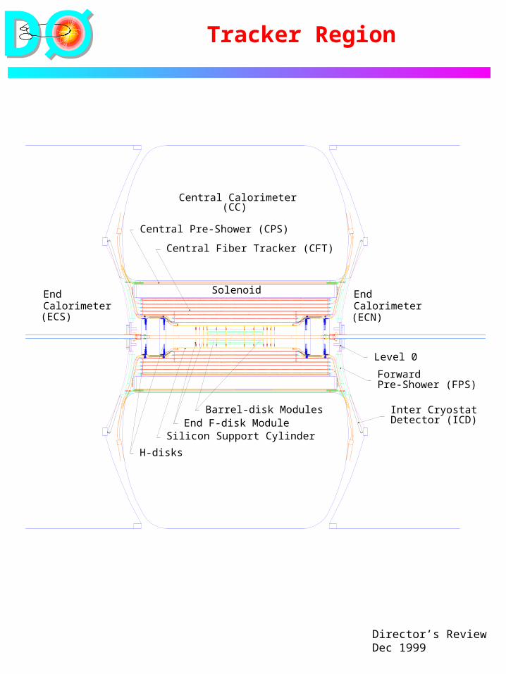
Tracker Region
Central Calorimeter
Solenoid EndCalorimeterCalorimeter
End
(CC)
(ECN)(ECS)
Level 0
Central Pre-Shower (CPS)
Central Fiber Tracker (CFT)
End F-disk Module
H-disks
Barrel-disk Modules
Silicon Support Cylinder
Forward Pre-Shower (FPS)
Inter Cryostat Detector (ICD)
DD
Director’s ReviewDec 1999
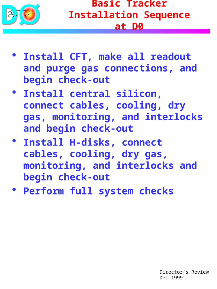
Basic Tracker Installation Sequence
at D0
Install CFT, make all readout and purge gas connections, and begin check-out
Install central silicon, connect cables, cooling, dry gas, monitoring, and interlocks and begin check-out
Install H-disks, connect cables, cooling, dry gas, monitoring, and interlocks and begin check-out
Perform full system checks
DD
Director’s ReviewDec 1999
Tracker Installation Considerations
Safety Procedures must be developed and
documented. JHA’s must be written. Personnel must receive the appropriate
training to properly perform their work. ORC’s must be obtained before each
critical operation is initiated.
Steps at D0 before CFT arrival Preliminary surveys are completed. The CFT gas system and associated
lines are installed and tested. Half of the VLPC readout cassettes are
installed and tested.
CFT readout bundles Bundles to the platform are installed
after the CFT is in place. All CFT bundles on a given face of the Central Calorimeter must be in place before silicon cables are installed on that face.
DD
Director’s ReviewDec 1999
Tracker Installation Considerations
Steps at D0 before silicon arrival The silicon cables and readout
electronics are installed and checked from adapter boards on the face of the central calorimeter onward towards the platform.
The silicon cooling system is installed.
The silicon dry gas system and associated lines are installed and tested.
Silicon steps at Lab C and Lab 3 The central silicon support cylinder is
pre-aligned with the CFT at Lab 3. A reproducible connection is provided.
Central silicon modules are cabled, checked, and pre-aligned within the support cylinder at Lab C.
Reproducible H-disk mounts are pre-aligned with the CFT at Lab 3.
All silicon modules are fully tested.
DD
Director’s ReviewDec 1999
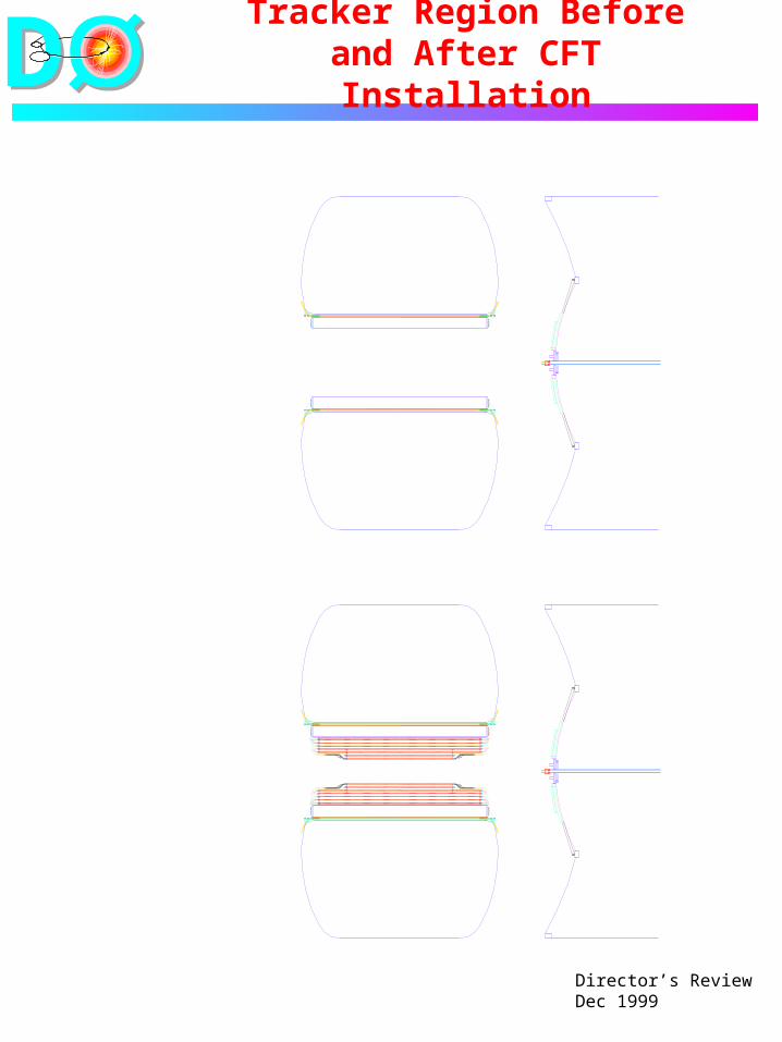
Tracker Region Before and After CFT Installation
DD
Director’s ReviewDec 1999
CFT Move and Installation at D0
CFT Move The CFT remains on its nesting cart
during the move to D0. A sheet metal enclosure and vinyl sheeting surround it.
CFT Installation at D0 Installation relies upon techniques
developed for installation of the solenoid magnet.
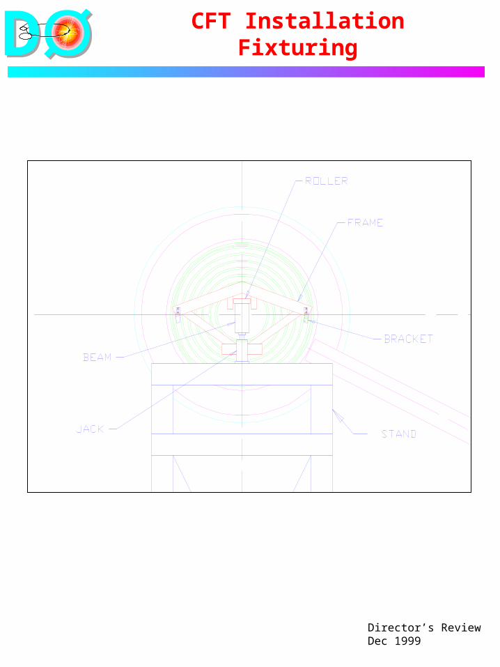
An installation I-beam is lifted by crane and placed through the CFT.
Fixturing spanning between the 3 and 9 o’clock support points is attached to each end of the CFT.
Carriages are placed between the fixturing and the I-beam and temporarily fastened to the beam.
DD
Director’s ReviewDec 1999
CFT Installation Fixturing
DD
Director’s ReviewDec 1999
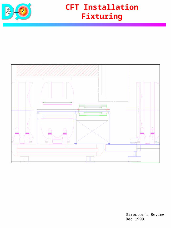
CFT Installation Fixturing
DD
Director’s ReviewDec 1999
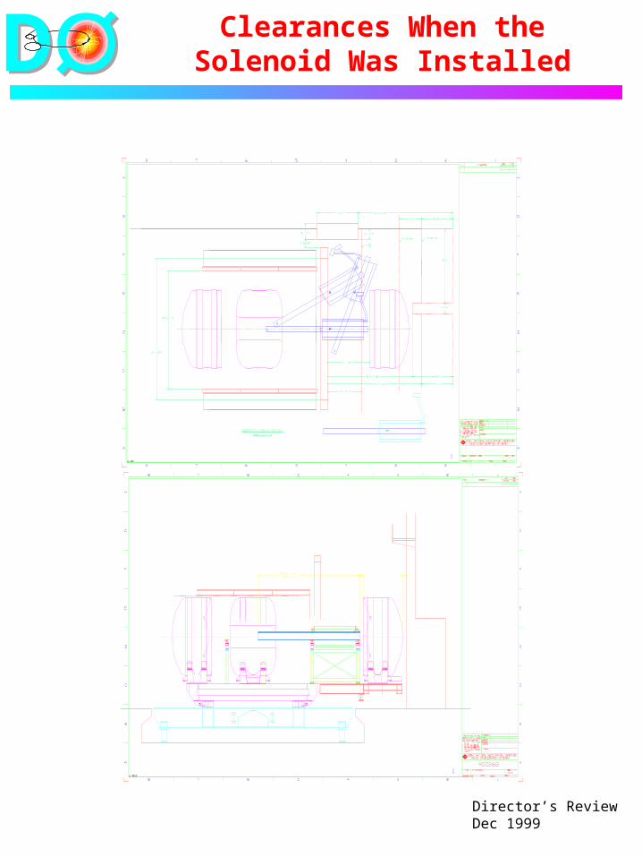
Clearances When the Solenoid Was Installed
DD
Director’s ReviewDec 1999
CFT Mechanical Installation
The I-beam, with the CFT as a counterweight, is lifted by crane, placed through the solenoid, and then supported from structures built up from the D0 center beam.
Hydraulic jacks under each end of the I-beam allow vertical positioning.
The CFT is rolled into position and lowered onto shim packs between brackets extending from the solenoid and brackets extending from the barrel 6 to 7 CFT connecting ring.
Purge gas lines for the CFT are connected and purging is initiated.

DD
Director’s ReviewDec 1999
CFT Installation
CFT alignment A survey crew or survey equipment
will be needed during the following alignment operations
Shim packs are adjusted to provide equal bearing on the four support locations and proper vertical and azimuthal alignment. The I-beam and its jacks serve as a lifting fixture for this operation.
After the 3 and 9 o’clock mounts have been adjusted, 6 o’clock mounts, which position only horizontally, are adjusted. Position along the beam line is locked at only one end.
The carriage and I-beam are removed.
Both ends of the CFT are cabled with clear readout bundles.
DD
Director’s ReviewDec 1999
CFT Installation
Checks associated with installation
Check-out with light pulsers commences as clear readout bundles are connected.
Check-out with cosmic rays commences when significant portions have been connected.
DD
Director’s ReviewDec 1999
Central Silicon Transport to D0
Shipping container A padded shipping container is used
to transport the central silicon tracker and the beam pipe from Lab C. Internal framing is likely to be needed.
The silicon, low mass cables, and beam pipe are bagged as a unit within the shipping container. A dry nitrogen atmosphere is provided.
Low mass cables The cables have already been
connected to HDI’s and anchored to the support cylinder.
The 360 cables per end emerge in 18 bundles of 20 cables each.
The bundle length beyond the end of the support cylinder is about 78”. The total cable weight extending beyond each end is about 15 pounds.
Bundles are coiled into separate bags of perhaps 9 bundles each.
DD
Director’s ReviewDec 1999
Central Silicon Transport to D0
Cooling manifolds Manifolds extend to the ends of the
support cylinder, which holds them. They have been connected to modules and used during Lab C testing.
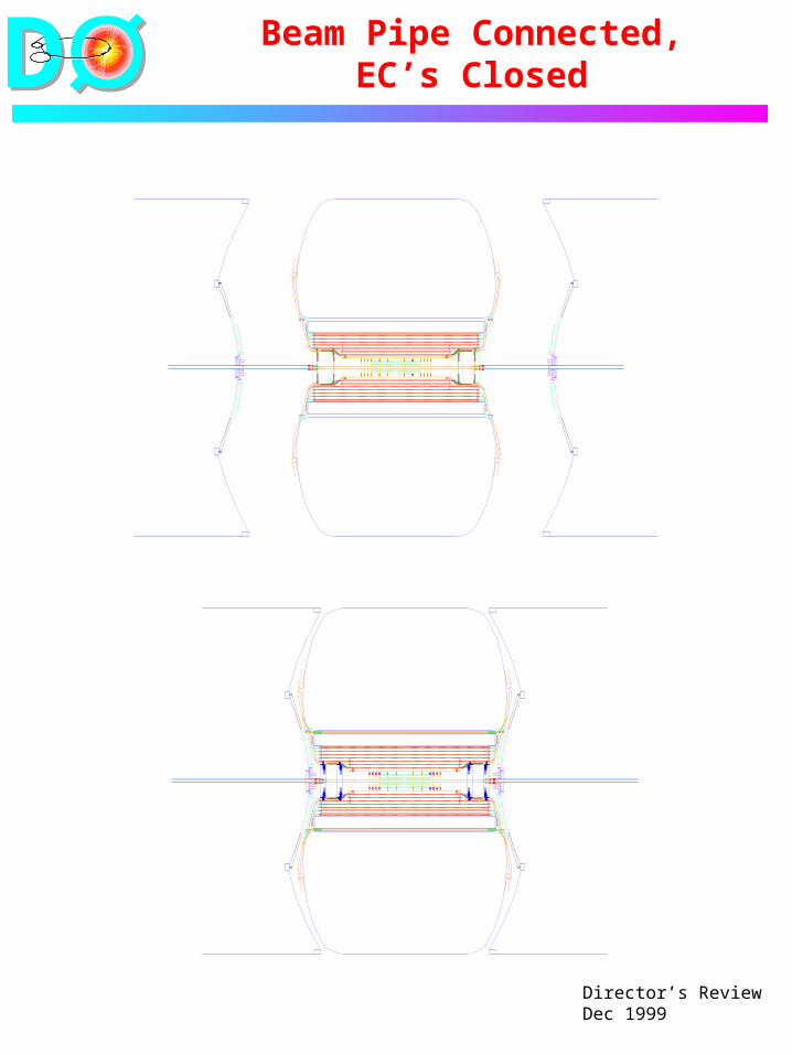
Beam pipe The 97” beryllium beam pipe will
have previously been installed through the silicon.
It is supported by the end flanges of the silicon support cylinder. Its transverse motion is limited by internal dividers within the support cylinder.
The beam pipe has been baked-out, leak checked, back-filled with nitrogen, and sealed.
DD
Director’s ReviewDec 1999
Central Silicon Installation
DD
Director’s ReviewDec 1999
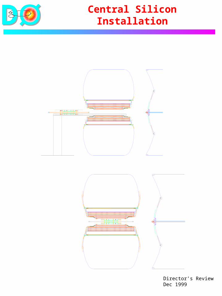
Central Silicon Installation at D0
Transport at D0 A frame will be provided to lift the
silicon support cylinder by its end flanges and support the bundles of low mass cables. The support cylinder, in turn, holds the beam pipe.
Preparation of installation fixturing
A 4 mm thick carbon-fiber cradle, extending approximately 45o from 6 o’clock, is installed through barrel 1 of the CFT. It rests on the CFT barrel 1 end rings and on an external stand built up from the D0 center beam.
A plastic sheet is placed upon the cradle to aid in moving the silicon tracker.
DD
Director’s ReviewDec 1999
Central Silicon Installation
Mechanical Installation The silicon tracker is lifted from its
shipping container and placed upon the installation cradle.
Low mass cable bundles are transferred from the lifting frame to the plastic sheet on the installation cradle as silicon installation progresses.
The plastic sheet on the installation cradle is drawn through the CFT carrying the central silicon and beam pipe with it.
The weight of low mass cable bundles is transferred to brackets on the CC face once the silicon support cylinder nears its final longitudinal position.
Upper half rings are pinned and screwed between the end flanges of the silicon support cylinder and the end rings of CFT barrel 1. The installation cradle is used as a lifting fixture during this operation.
DD
Director’s ReviewDec 1999
Central Silicon Installation
The installation cradle is lowered and removed. (Radial clearance ~ 3 mm).
Lower half rings are pinned and screwed between the end flanges of the silicon support cylinder and the end rings of CFT barrel 1.
DD
Director’s ReviewDec 1999
Central Silicon Installation
Connection of services Silicon cooling connections are made at
each end of the support cylinder. Lines are anchored from the inner surface of CFT barrel 3, the solenoid, and the CC face. Thermal insulation is added. Leak checking of the cooling system commences.
Dry gas lines to the central silicon region are connected and anchored from the inner surface of CFT barrel 3, the solenoid, and the CC face. Purging is initiated with dry air.
Lines for dewpoint and cooling system temperature, flow, and pressure sensors are connected, anchored, and checked. Sensors are inter-calibrated.
The monitoring and interlock system is checked.
When these checks have been completed, flow of coolant, with the coolant temperature limited so that it is above the dewpoint, is begun.
DD
Director’s ReviewDec 1999
Silicon Installation
Beam pipe A dry nitrogen purge is established
through the beam pipe as soon as the pipe is in its installed position. The purge must be properly vented.
Low mass cables Low mass cables are dressed along
the inner surface of CFT barrel 3 and anchored to the surface.
Connecting of low mass cables to adapter boards is begun on one face of the CC and progresses to the other.
The cables are dressed and anchored to the CC face as they are installed.
HDI’s are individually powered and checked as their cables are connected.
F-disk radiation monitors Cables for radiation monitors on the
F-disks are connected, anchored, and checked.
DD
Director’s ReviewDec 1999
Central Silicon Installation
Central silicon check Temporary dry gas enclosures are
installed in the H-disk region. Monitoring and interlocks are
checked again. The coolant temperature is lowered
to a temperature conservatively above the observed dewpoint of the central silicon region.
The full central silicon system is powered and checked before H-disks are installed.
DD
Director’s ReviewDec 1999
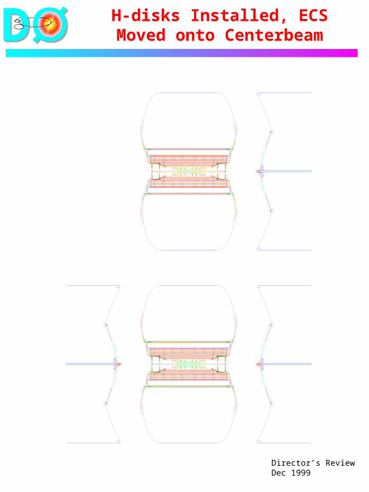
H-disks Installed, ECS Moved onto Centerbeam
DD
Director’s ReviewDec 1999
H-disk Installation
Preparations for H-disk installation Power is removed from the central
silicon. The coolant temperature is raised until
it is conservatively above the ambient dewpoint.
Coolant flow is halted. The temporary dry gas enclosures are
removed from the H-disk region.
H-disk installation H-disks are individually installed with
the aid of a handheld installation fixture.
Kinematic mount halves are joined to their mates previously installed on the inner surface of CFT barrel 3.
H-disk cables, cooling lines, and dry gas purge lines are connected, anchored, and checked.
Coolant flow is resumed once all H-disks have been installed and connected.
Each H-disk is powered and checked.

DD
Director’s ReviewDec 1999
Silicon Installation
Completion of installation Cables for radiation monitors on the
H-disks are connected, anchored, and checked.
Dry gas enclosures are completed. Sensors, monitors, and interlocks
are rechecked.
Cooldown to operating temperature and final check-out begin.
DD
Director’s ReviewDec 1999
Beam Pipe Connected, EC’s Closed
DD
Director’s ReviewDec 1999
CFT Alignment Prior to Installation
Survey balls mounted on the barrel 6 to 7 connecting rings at each end of the CFT provide a reference system.
Individual barrels are aligned relative to each other during “nesting” and their positions are measured relative to the survey balls.
The survey balls provide the primary reference thereafter.
The alignment process relies heavily upon the Lab 3 LK coordinate measuring machine (CMM).
Custom touch probe extensions may be needed for some alignment processes.
DD
Director’s ReviewDec 1999
Central Silicon to CFT Alignment
Work at Lab 3 The silicon support cylinder (without
silicon) is aligned within CFT barrel 1 in Lab 3 after all CFT barrels have been nested.
The work relies heavily upon the Lab 3 LK CMM.
The reference system for module installation is established by balls at the ends of the support cylinder
Silicon modules and cables are not present, but weights are used to simulate the deflections they would produce.
Transverse alignment tolerance between the silicon support cylinder and the CFT = 50 m.
Reproducibility of alignment is set by pinning.
DD
Director’s ReviewDec 1999
Silicon Module Installation in the Support Cylinder
Module installation and alignment in Lab C
The silicon support cylinder is returned to Lab C and positioned on the LK CMM for module installation.
Weights to simulate those of cables and modules are installed in the support cylinder. Weights are removed as modules are installed.
Module installation progresses from z = 0 outward.
Separable, adjustable kinematic mounts at 3, 6, and 9 o’clock are connected as modules are installed.
The kinematic mounts are adjusted to align each module with respect to the support cylinder to 10 m. Alignment is performed with the aid of the Lab C LK CMM.
DD
Director’s ReviewDec 1999
Silicon Module Installation at Lab C
Connections, checks, and services
Cooling lines and temporary cables are connected as modules are installed.
An initial readout check is made as each module installed with cooling limited to the ambient dewpoint.
The cover of the support cylinder is installed after all modules are in place.
Final readout cables are installed, connected, and anchored.
Individual modules are checked again as final cables are installed.
When all cables are in place, module alignment is re-measured and adjusted.
A temporary dry gas enclosure is installed and modules are checked at operating temperature.
DD
Director’s ReviewDec 1999
H-disk Alignment
H-disk mounts and Lab 3 work Mounts rely upon three balls in slots
to establish reproducibility. A single screw holds each separable mount assembly together.
Reproducibility of the separable mounts is 3 m.
Leaf springs constrain in two directions and allow motion in the third.
Mounts are brought into CFT barrel 3 using an installation plate and a six axis adjustment system.
The Lab 3 CMM provides positioning information.
The mounts are epoxied into place. Then they are disconnected so that one mount half can remain on CFT barrel 3 and the other can be removed along with the installation plate.
DD
Director’s ReviewDec 1999
H-disk Alignment
H-disk installation at D0 Final installation at D0 is performed
with the aid of a hand-held lifting plate.
Each disk is lifted into position and fastened with individual screws at 3, 6, and 9 o’clock.
Then the lifting plate is removed and a fourth screw, which aids in z-positioning only, is added at 12 o’clock.
DD
Director’s ReviewDec 1999
Manpower for Tracker Integration and
Installation
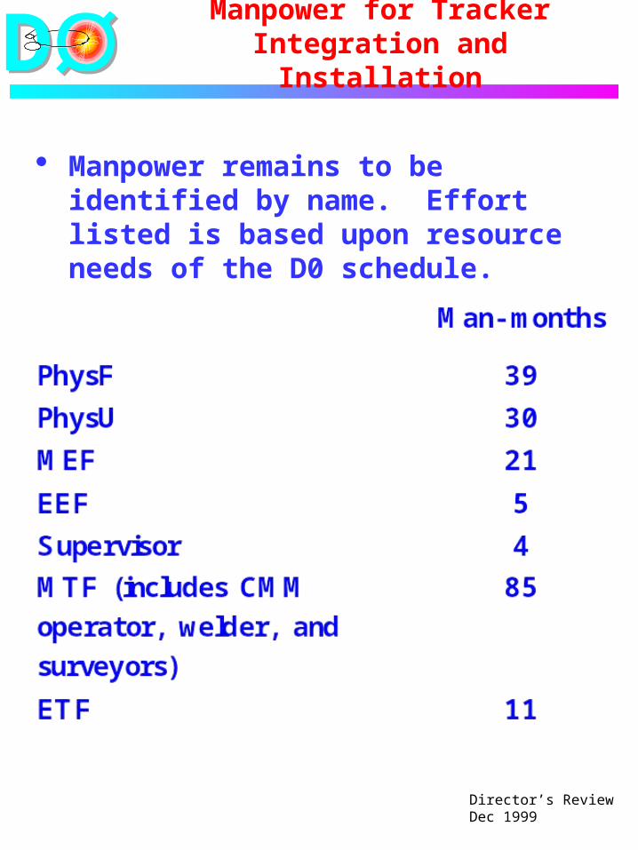
Manpower remains to be identified by name. Effort listed is based upon resource needs of the D0 schedule.

DD
Director’s ReviewDec 1999
Tech Effort for Tracker Integration and
Installation
Silicon Tracker Tech EffortFNAL
0
5
10
15
20
25
Jan-
99
Mar
-99
May
-99
Jul-9
9
Sep
-99
Nov
-99
Jan-
00
Mar
-00
May
-00
Jul-0
0
Sep
-00
Nov
-00
Jan-
01
FT
Es
All
Install.
Actual
Plus Reqs
Fiber Tracker Tech EffortFNAL
0
5
10
15
20
25
30
Jan-
99
Mar
-99
May
-99
Jul-9
9
Sep
-99
Nov
-99
Jan-
00
Mar
-00
May
-00
Jul-0
0
Sep
-00
Nov
-00
Jan-
01
FT
Es
All
Install.
Actual
Plus Reqs
DD
Director’s ReviewDec 1999
Conclusions
A group responsible for tracker integration and installation has been formed.
Much progress has been made to understand the steps for installing the CFT and silicon.
Manpower remains to be identified in detail.