Embed Size (px)
Citation preview

1
DIRECTORATE OF TECHNICAL EDUCATION, CHENNAI-25
DIPLOMA EXAMINATIONS-OCT-2019
DEPT : COMPUTER ENGINEERING
SUBJECT : COMPUTER HARDWARE AND SERVICING
QCODE/SUB CODE : 908/ 35261
PART A
1. Define chipsets.
A chipset is a set of electronic components in an integrated circuit that manages the data
flow between the processor, memory and peripherals. It is usually found on the motherboard.
2.What is memory speed?
This is simply the speed at which the memory is rated to run. If the memory is rated at
DDR3-1600 (PC3-12800), it's rated to run on a 800MHz Front Side Bus. Since it processes data
on both the rising and falling edges of the clock pulse, it acts as 1600MHz RAM.
3.Write any two blu-ray disc parameters.
(i) Optical Parameters
(ii)Disk Structure Parameters
(iii) Data Management Parameters
4.Write the principles of LCD.
LCD - Liquid crystal display screen works on the principle of blocking light rather than
emitting light. LCDs require backlight as they do not emits light by them. Cathode ray tube draw
more power compared to LCDs and are also heavier and bigger.
5.What is AMI?
The AMI or Award BIOS id appears at the bottom of the screen after power on, during
memory count up. The PAUSE key should work at that point, allowing one to write down the
BIOS number, the BIOS date, and the version.

2
6. What is ESD?
Electrostatic discharge (ESD) is the sudden flow of electricity between two electrically
charged objects caused by contact, an electrical short, or dielectric breakdown. A buildup of
static electricity can be caused by tribocharging or by electrostatic induction.
7. Write the basics of mobile communication.
In the first half of the 20th century radio broadcast was used. There is one transmitter, the
so-called radio station. Information, such as news, music, etc. is transmitted from the radio
station to the receiver equipment, the radio device. This type of one-way transmission is called
simplex transmission. The transmission takes place only in one direction, from the transmitter
tothe receiver. The transmission in which information flow can take place in two directions is
called duplex transmission. In Walky-talky transmission of user data take place in two directions,
but there was a limitation: The users were not allowed to transmit at the same time. In other
words, either receive or transmit takes place. This type of transmission is therefore often called
semi-duplex transmission. For telephony services, a technical solutions is required, where
subscribers have the impression, that they can speak (transmit) and hear (receive)
simultaneously. This type of transmission solution is regarded as full duplex transmission.
8.Define application software.
A software which is developed to help the user to perform specific tasks is
called application software.
PART B
9.Explain RTC.
A real-time clock (RTC) is a computer clock that keeps track of the current time. RTCs
often have an alternate source of power, so they can continue to keep time while the primary
source of power is off or unavailable. This alternate source of power is normally a lithium
battery in older systems, but some newer systems use a super capacitor because they are
rechargeable and can be soldered.

3
10.Write short notes on core i3.
Core i3
Intel intended the Core i3 as the new low end of the performance processor line from
Intel. The first Core i3 processors were launched on January 7, 2010.The first Nehalem based
Core i3 was Clarkdale-based, with an integrated GPU and two cores. The Core i3-3xxM
processors are based on Arrandale, the mobile version of the Clarkdale desktop processor. They
are similar to the Core i5-4xx series but running at lower clock speeds and without Turbo Boost.
11.Explain solid state drive.
An SSD (solid-state drive or solid-state disk) is a nonvolatile storage device that stores
persistent data on solid-state flash memory. SSD devices embed silicon-based memory chips as
the storage media for the writing and reading of persistent data.
SSDs, also known as flash drives or flash cards, are inserted into slots in computer
servers referred to as server-side flash storage or as part of an enterprise flash storage array
system. Sometimes the flash devices are called solid-state hard drives, although that term is
misleading.
12.Explain plasma display.
Research on plasma displays began in the United States over four decades ago, in 1960.
The technology was developed by four researchers: Bitzer, Slottow, Willson, and Arora. The
first prototype came out very quickly, in 1964. The matrix, which was revolutionary for its time,
consisted of 4 x 4 pixels emitting monochrome blue light. Then, in 1967, the size of plasma
matrices increased to 16 x 16 pixels, this time emitting a pale red light, still monochrome, using
neon.

4
3.Draw the block diagram of laptop.
14.Explain battery booster.
It is used to boost the power of battery of a mobile phone.

5
15.Explain jumper techniques.
Most mobile phone repairing is done by doing jumper. Different parts of a mobile cell
phone like display, keypad, speaker, microphone, LED lights, different ICs, different small
parts and electronic components, all have different jumper settings. It is important to first track
the fault or missing track and then do the jumper.
✓ Mobile phone jumper wire.
✓ Soldering iron.
✓ Solder wire.
✓ Blade cutter.
✓ Multimeter.
✓ Soldering flux.
✓ PCB holder.
✓ Tweezers.
16.Write a note on bar code scanner.
Barcode Scanner
Barcode scanners have become such a ubiquitous technology that it is easy to take the
complexity of their underlying designs for granted. Barcode scanners require multiple discrete
integrated circuits and an array of passive and active circuitry to provide the functionality and
reliability that end users have come to expect. Many barcode scanners generally use an optical
sensor, such as a charge-coupled device (CCD), which outputs an analog representation of what
is ―visible‖ to the sensor to an analog-to-digital converter (ADC) controlled by a
microcontroller (MCU). The MCU interprets the ADC‘s output as a sequence of thick and thin
black and white bars and processes this sequence further to derive a string of characters from the
pattern.
PART C
17. (a) Explain: (i) Core 2 Duo processor 5marks (ii) Xeon processor.5 marks
(i) Core 2 Duo processor: (Description 3 mark diagram 2 marks)
Core2 Duo processor
Core 2 is basically a brand name which refers to the wide range of Intel’s processors.
These models are embedded on single die or integrated circuit which is embedded on the two
ICs. This technique enables the user to perform multiple tasks simultaneously using software and
processor at the same time. The ranges of products associated with the core 2 Duo technology

6
are listed in table Intel core 2 duo processors come in both 45nm and 65nm having
virtualization, trusted execution technology and clock speed of about 2 GHz.
TABLE Range of Products associated with the Core 2 Duo Technology
Processor type Year of release Features
E4300 2007 L2 cache of 2 MB
E4400 April 2007
E4500 and E4600 October 2007
E4700 March 2008 Frequency rate of 2600 MHz
Features
It has sustained backward compatibility with the software and existing hardware.
It is efficient enough to run two operating systems at a time by help from working virtual
machines. (The virtual machines are smart enough to share physical hardware, having
separate operating system and busy running their own applications.)
It has advanced security features and enables to set the trusted Platform Module.
It has L2 cache. Its size varies from 1 MB to 6 MB.
Its operating speed varies from 1.8 GHz to 3.3 GHz. The speed of front side bus is 533 or
800 MHz or 1066 MHz or 1333 MHz or 1600 MHz
Figure shows the memory structure of core duo processor.

7
(ii) Xeon processor: (Description 2 mark, diagram 3 marks)
The Xeon is a brand of x86microprocessors designed, manufactured, and marketed by
Intel Corporation. It has multi-socket, higher core counts, and support for ECC memory. A Xeon
Phi co-processor can be used with existing Xeon processor to provide increased computing
power, requiring an available PCI Express 3.0 x16 slot in x16, or x8 mode. Intel Xeon CPUs
support the following chipsets: Z87, X99, and for dual CPUs the C600 series of chipsets.
Disadvantages of Xeon processors are unsuitable for most consumer-grade desktop PCs, lower
clock rates, absence of an integrated GPU, and non-existent support for over clocking. Despite
such disadvantages, Xeon processors preferred by desktop users, (primarily gamers, and extreme
users) mainly due to higher core count potential, and higher price to performance ratio vs. the
Core i7. Because Intel Xeon CPUs lack an integrated GPU, they require graphics installed in an
available PCI Express x16 slot.
Xeon features:
It has faster L1 and L2cache , either 512 Kbytes or 1 Mbytes, which runs at the same 400
MHz clock speed of the processor.

8
A faster bus to carry data between the processor, RAM, and I/O devices. The 450NX PCIset
is a chipset that works at a 100 Mhz clock speed and supports up to 8 GB of extended
data output RAM memory.
A larger Accelerated Graphics Port ( AGP ) chip set called the 440GX AGP set that also runs
at 100 Mhz. It supports 2 GB of 100 Mhz SDRAM .
An extended server memory architecture that provide for 36-bit addresses, allowing up to 64
GB of physical memory to be addressed.
It has 32 or 64 bit instruction set. Figure shows the block diagram of Xeon wood crest
processor having two cores.
(OR)
(b)Explain north/south bridge architecture with neat diagram. (Description 3 mark
diagram 2 marks)
North/South Bridge architecture
North bridge is connected directly to the CPU via the front side bus (FSB) and is responsible for
tasks that require the highest performance. The north bridge is usually paired with a south bridge,
also known as I/O controller hub. These two chips manage communications between the CPU
and other parts of the motherboard, and constitute the core logic chipset of the PC motherboard.
Integrating more functions onto fewer components, decreases overall motherboard cost and
improves performance.
The advantage of integrating the memory controller on the CPU reduces the latency from the
CPU to memory.
The functionality of the Southbridge is as follows:
i. PCI bus. The PCI bus supports the traditional PCI specification, but may also include support
for PCI-X and PCI Express (PCIe).
ii. ISA bus or LPC bridge. ISA support remains an integrated part of the modern south bridge,
though ISA slots are no longer provided on more recent motherboards. The LPC bridge provides
a data and control path to the super I/O (the normal attachment for the keyboard, mouse, parallel
port, serial port, IR port, and floppy controller) and FWH (firmware hub which provides access
to BIOS flash storage).
iii. SPI bus. The SPI bus is a simple serial bus mostly used for firmware (e.g., BIOS) flash
storage access.
iv. SM Bus. The SM Bus is used to communicate with other devices on the motherboard (e.g.,
system temperature sensors, fan controllers, SPDs).
v. DMA controller. The DMA controller allows ISA or LPC devices direct access to main
memory without needing help from the CPU.

9
vi. Interrupt controllers such as 8259A and/or I/O APIC. The interrupt controller provides a
mechanism for attached devices to get attention from the CPU.
vii. Mass storage controllers such as PATA and/or SATA. This typically allows direct
attachment of system hard drives.
viii. Real-time clock. The real time clock provides a persistent time account.
ix. Power management (APM and ACPI). The APM or ACPI functions provide methods and
signaling to allow the computer to sleep or shut down to save power.
x. Nonvolatile BIOS memory. The system CMOS (BIOS configuration memory), assisted by
battery supplemental power, creates a limited non-volatile storage area for system configuration
data
xi. Intel High Definition Audio sound interface.
xii. Out-of-band management controller such as a BMC or HECI. Optionally, a south bridge also
includes support for Ethernet, RAID, USB, audio codec, and FireWire. Where support is
provided for non-USB keyboard, mouse, and serial ports, a machine normally does so through a
device referred to as a Super I/O; still more rarely, a south bridge may directly support the
keyboard, mouse, and serial ports.
The architecture of North bridge and South bridge is shown in Figure

10
18. (a) Explain the construction and working principle of hard disk. 10 marks
(construction 5 marks working principle 5 marks)
Hard disk
A hard disk drive (sometimes abbreviated as Hard drive, HD, or HDD) is a non-volatile
memory hardware device that permanently stores and retrieves information. There are many
variations, but their physical sizes are 3.5" and 2.5" for desktop and laptop computers
respectively. A hard drive consists of one or more platters to which data is written using a
magnetic head, all inside of an air-sealed casing. Internal hard disks reside in a drive bay,
connect to the motherboard using an ATA, SCSI, or SATA cable, and are powered by a
connection to the PSU (power supply unit). Construction
Hard disk drives are otherwise called Winchester disk. A hard disk consists of number of
disks called platters coated with magnetic material on both sides put together on a common shaft
or spindle. These disks are not removable.
Spindle & Motor
A hard drive's motor rotates the platter (or platters) counter-clockwise at speeds measured
in revolutions per minute (RPM). The speed varies depending on the individual hard drive and
manufacturer. Spindles spin continuously unless the hard drive is set up to go into a sleep mode
when it is inactive or idle (not being used).
Actuator
The actuator is the device used to position the head arms to different tracks on the surface
of the platter (actually, to different cylinders, since all head arms are moved as a synchronous
unit, so each arm moves to the same track number of its respective surface).The actuator is a
very important part of the hard disk, because changing from track to track is the only operation
on the hard disk that requires active movement: changing heads is an electronic function, and
changing sectors involves waiting for the right sector number to spin around and come under the
head (passive movement). Changing tracks means the heads must be shifted. So making sure this
movement can be done quickly and accurately is of paramount importance.

11
Figure shows the organization of hard disk. The surface of the drive platter is
organized with coordinates, much like a map. Data is stored in concentric tracks on the
surfaces of each platter. (A platter has two sides, and thus, two data recording surfaces.) A
typical disk drive can have more than 2,000 tracks per inch (TPI) on its recording surface. A
cylinder describes the group of all tracks located at a given head position across all platters.
To allow for easier access to data, each track is divided into individually addressable sectors.
The process of organizing the disk surface into tracks and sectors is called formatting, and
almost all hard disk drives today come preformatted by the manufacturer. The process of
formatting a hard drive applies addressing data to the platter's surface. In almost all systems,
including PCs and Macintoshes, sectors typically contain 512 bytes of user data plus
addressing information used by the drive electronics (although some proprietary systems use
other sector lengths).
The disk drive controller, which resides on the drive's PCB, uses the formatting
information and addresses - much like a tourist uses a city map - to guide data into and out of
a specific location on the hard drive. Without formatting instructions, neither the controller
nor the operating system would know where to store data or how to retrieve it. In earlier hard
drive designs, the number of sectors per track was fixed and, because the outer tracks on a
platter have a larger circumference than the inner tracks, space on the outer tracks was
wasted.

12
The number of sectors that would fit on the innermost track constrained the number
of sectors per track for the entire platter. However, many of today's advanced drives use a
formatting technique called Multiple Zone Recording to pack more data onto the surface of
the disk. Multiple Zone Recording allows the number of sectors per track to be adjusted so
more sectors are stored on the larger, outer tracks. By dividing the outer tracks into more
sectors, data can be packed uniformly throughout the surface of a platter, disk surface is used
more efficiently, and higher capacities can be achieved with fewer platters. The number of
sectors per track on a typical 3.5-inch disk ranges from 60 to 120 under a Multiple Zone
Recording scheme. Not only is effective storage capacity increased by as much as 25 percent
with Multiple Zone Recording, but the disk-to-buffer transfer rate is also boosted. With more
bytes per track, data in the outer zones is read at a faster rate. Quantum Corporation is a
pioneer in Multiple Zone Recording, and was the first manufacturer to implement Multiple
Zone Recording on 2.5-inch disk drive products.
Working Principle
Reading
When the computer wants to read data, the operating system works out where the data is
on the disk. To do this, it first reads the FAT (File Allocation Table) at the beginning of the
partition. This tells the operating system in which sector on which track to find the data. With
this information, the head can then read the requested data. The disk controller controls the
drive‘s servo-motors and translates the fluctuating voltages from the head into digital data for the
CPU.
More often than not, the next set of data to be read is sequentially located on the disk. For
this reason, hard drives contain between 256KB and 8MB of cache buffer in which to store all
the information in a sector or cylinder in case it‘s needed. This is very effective in speeding up
both throughput and access times. A hard drive also requires servo information, which provides a
continuous update on the location of the heads. This can be stored on a separate platter, or it can
be intermingled with the actual data on all the platters. A separate servo platter is more
13
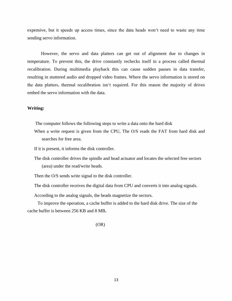
expensive, but it speeds up access times, since the data heads won‘t need to waste any time
sending servo information.
However, the servo and data platters can get out of alignment due to changes in
temperature. To prevent this, the drive constantly rechecks itself in a process called thermal
recalibration. During multimedia playback this can cause sudden pauses in data transfer,
resulting in stuttered audio and dropped video frames. Where the servo information is stored on
the data platters, thermal recalibration isn‘t required. For this reason the majority of drives
embed the servo information with the data.
Writing:
The computer follows the following steps to write a data onto the hard disk
When a write request is given from the CPU, The O/S reads the FAT from hard disk and
searches for free area.
If it is present, it informs the disk controller.
The disk controller drives the spindle and head actuator and locates the selected free sectors
(area) under the read/write heads.
Then the O/S sends write signal to the disk controller.
The disk controller receives the digital data from CPU and converts it into analog signals.
According to the analog signals, the heads magnetize the sectors. To improve the operation, a cache buffer is added to the hard disk drive. The size of the
cache buffer is between 256 KB and 8 MB.
(OR)

14
(b)Explain the operation of inkjet printer with neat diagram. 10marks(description 7marks
diagram 3marks)
Inkjet Printer
Inkjet printing has two benefits over laser printers: lower printer cost and color-printing
capabilities. But while inkjet printers are priced much less than laser printers, they are actually
more expensive to use and maintain. Cartridges need to be changed more frequently and the
special coated paper required to produce high-quality output is very expensive. At a cost per
page level, inkjet printing costs about 10 times more than laser printing.
Operation
Inkjet printing is a liquid deposition technique, by which the droplets of the ink were
ejected with the same volume and printed on the substrate. It is a low cost, material-conserving,
non-contact, additive patterning, and mask less approach with the scalability to large area
manufacturing. According to the formation of the uniform drops, printers are classified into two
categories: continuous inkjet printer and drop-on-demand (DOD) inkjet printer.
For continuous inkjet printer, the ink ejected by the high pressure is broken into uniform
droplets by electromechanical devices, at the same time the droplets are charged and directed to
the desired place in the presence of the deflecting electrode. Figure shows the schematic of the
continuous inkjet printer. This type of inkjet printer possesses high-frequency drop generation;
however, the cost is also high as its great space requirement and the complicated ink system. It is
best suited for graphic arts and industrial applications.

15
For DOD inkjet printers, the drops were generated by the volume changes of the channel caused
by the applied voltage on the piezoelectric materials of the channel wall. Figure2.26 shows the
actuator principle of ejecting uniform drops from the ink. At the beginning the voltage is applied
on one channel and with the piezoelectric effect, the channel is enlarged and filled with the ink;
then the voltage will be applied to the neighbor channel, which is enlarged and at the same time
the first channel will shrink and release a drop of ink. Thus by Applying voltage on channels, the
ink can be ejected as a form of drop and printed on substrate as the pattern desired.
There is another type of DOD printer, bubble jet, which is thermal driven. The stream
pocket is produced in the channel by the heating element. As the applied voltage, the resistor
heat up and produces bubble which forces the ink to jet out to form drop. The schematic of DOD
inkjet printer in which the droplets are produced by applying voltage according to the print
desired.
The DOD printer system is less complex than the continuous printers, and thus the cost will be
lower. It is the commercially available inkjet printer today.
19. (a) Explain the working principle of TFT display.
TFT Displays
A display screen made with TFT (thin-film transistor) technology is a liquid crystal
display (LCD), common in notebook and laptop computers, that has a transistor for each pixel.
Having a transistor at each pixel means that the current that triggers pixel illumination can be
smaller and therefore can be switched on and off more quickly.

16
TFT is also known as active matrix display technology. A TFT or active matrix display is
more responsive to change.
A more recent development is organic thin-film transistor technology, which makes it
possible to have flexible display surfaces.
Construction:
The only difference is that, the TFT LCD has a sandwich-like structure with liquid crystal
filled between two glass plates. From the figure, TFT Glass has as many TFTs as the number of
pixels displayed. The Color Filter Glass has color filter which generates color. Figure Shows the
TFT Display
The Liquid Crystal Displays (LCDs) have the tendency to change the properties of light
passing through the crystals, when they are stimulated by some external electrical charge.
With this property, the Liquid crystals move according to the difference in voltage
between the Color Filter Glass and the TFT Glass. The amount of light supplied by Back
Light is determined by the amount of movement of the liquid crystals in such a way as to
generate color. Working:
All that is required for LCD pixels to create color is to place a color filter in front of each
pixel. By using red, green, and blue color filters, the required primary colors are generated to
produce the millions of color variations needed for graphics and video display. Modern LCD
technology uses what is known as Thin-Film Transistor (TFT) technology. Each pixel has its
own transistor and capacitor, which increase the contrast rating of the LCD due to the increased
retention of charge. It is shown in Figure

17
This helps to dramatically increase the response time for each pixel as they are scanned.
Control of each pixel is simply a matter of addressing a particular column and individually
activating each pixel in that row with a properly timed address pulse on the horizontal plane. The
higher the pulse level, the more the crystals align, producing a lower light output. TFT-LCD
screens consume a significantly higher amount of energy than other display technologies and are
normally found in LCD computer monitors or lower-end and older cell phones.
(OR)
(b) Explain error messages and beep codes in POST. (error message 5marks beep codes 5
marks)
POST
POST is a series of program routing in the motherboard ROM firmware and is used to
check the system components. This was introduced by IBM in 1981. When we switch on the
computer, POST is executed first and automatically performs a series of tests that check the
various components in the system. The components tested by POST are CPU, ROM,
motherboard support circuitry memory and major peripherals.
Whenever a faculty component is found, it gives an error or warning message. There are
two types of error message. They are Audio error codes and display error codes. The POST
programs are stored in the final 8 KB area of the 1 MB BIOS ROM. Once the computer is
switched on or reset, the microprocessor starts processing POST from memory address FFFF0.

18
Error
Error is a warning given by the system during POST for a faulty hardware component.
Beep Codes
Some number of short beeps that are sounded by the BIOS upon startup when a memory,
cache or processor error is encountered. There are numerous beep code patterns, and Phoenix
BIOS codes are long and short beeps delivered in groups. The following beep codes are for AMI
BIOSs.
Beep - Refresh Failure-Reseat/replace memory, troubleshoot motherboard.
Beeps - Parity Error-Reseat/replace memory, troubleshoot motherboard.
Beeps - Memory Error (first 64KB)-Reseat/replace memory.
Beeps - Timer Failure-Troubleshoot motherboard.
Beeps - Processor Failure-Troubleshoot CPU, motherboard.
Beeps - Keyboard Controller Failure-Troubleshoot keyboard, motherboard.
Beeps - Virtual Mode Exception Error-Troubleshoot CPU, motherboard.
Beeps - Display Memory Failure-Troubleshoot graphics card, motherboard.
Beeps - ROM BIOS Checksum Failure-Replace ROM BIOS, troubleshoot motherboard.
Beeps - CMOS Shutdown Register Failure-Troubleshoot motherboard.
Beeps - L2 Cache Failure-Troubleshoot L2 cache, motherboard.
Continuous Beeps - Memory or Video Failure-Troubleshoot memory, graphics card, mother-
board.
19
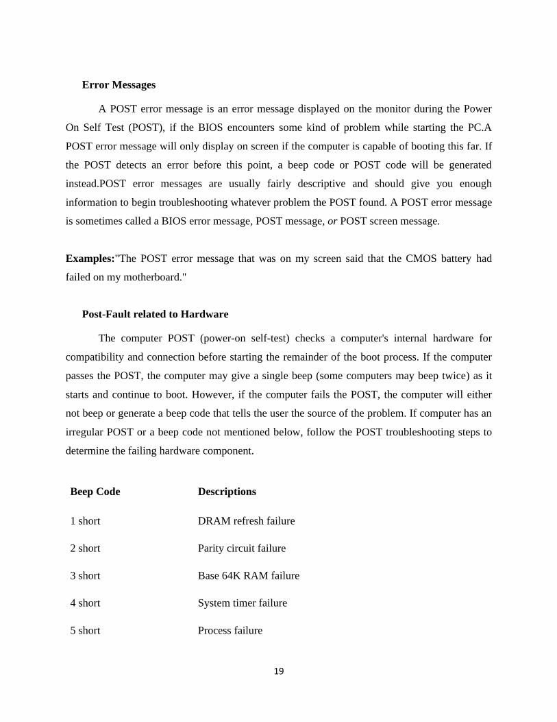
Error Messages
A POST error message is an error message displayed on the monitor during the Power
On Self Test (POST), if the BIOS encounters some kind of problem while starting the PC.A
POST error message will only display on screen if the computer is capable of booting this far. If
the POST detects an error before this point, a beep code or POST code will be generated
instead.POST error messages are usually fairly descriptive and should give you enough
information to begin troubleshooting whatever problem the POST found. A POST error message
is sometimes called a BIOS error message, POST message, or POST screen message.
Examples:"The POST error message that was on my screen said that the CMOS battery had
failed on my motherboard."
Post-Fault related to Hardware
The computer POST (power-on self-test) checks a computer's internal hardware for
compatibility and connection before starting the remainder of the boot process. If the computer
passes the POST, the computer may give a single beep (some computers may beep twice) as it
starts and continue to boot. However, if the computer fails the POST, the computer will either
not beep or generate a beep code that tells the user the source of the problem. If computer has an
irregular POST or a beep code not mentioned below, follow the POST troubleshooting steps to
determine the failing hardware component.
Beep Code Descriptions
1 short DRAM refresh failure
2 short Parity circuit failure
3 short Base 64K RAM failure
4 short System timer failure
5 short Process failure

20
6 short Keyboard Controller Failure
7 short Virtual mode exception error
8 short
Display memory Read/Write test
failure
9 short ROM BIOS checksum failure
10 short CMOS shutdown Read/Write error
11 short Display/retrace text failed
Continuous No power, Memory
1 long and 1 short Motherboard failure
1 long and 2 short Video adapter card failure
1 short and no display Video cable and /or display
1short and no boot Disk cable, adapter failure.
20. (a) Draw the block diagram of laptop mother board and explain.
Laptop Mother Board
The motherboard is the largest card in the computer and it is the one to which all other
cards and the CPU are attached. Both laptops and desktops contain motherboards, but
those in laptops are much more difficult to repair since the components are all packed in
so tightly. The motherboard's primary purpose is to manage all the computer's
subsystems. A chipset manages communications among systems. The motherboard
also distributes power to the systems with low power needs. Block Diagram
Socket (CPU sockets)
There are different types depending on the CPU socket type
motherboard
On the Main board Socket 370 Pentium 3

21
Socket 478 Pentium 4 motherboard on the
Socket 478 Pentium 4 motherboard on the
Socket pins controlled by the chipset north.
North Bridge (north Chipset)
Chipset North is responsible for control of high speed components like CPU,
RAM and Video Card
Chipset BUS speed control and switch control data, ensuring data back and
forth between the components is a smooth and continuous, fully exploit the speed of the
CPU and RAM
It can be a chipset like the traffic in an intersection, as drivers switch traffic
lights to allow each data stream passes through a period of time, while speed control is a
BUS different directions of the intersection, the vehicle must run on a specified speed.
South Bridge (south Chipset)
The function is similar as chipset north, but the south bridge driver chipset components
slower as: Sound Card, Net Card, hard disk, CD ROM drive, USB port, SIO and BIOS IC
etc..
ROM BIOS (Read Only Memory - Basic In Out System)
ROM is read-only memory IC, BIOS is a program loaded in ROM by the manufacturer
loaded Main board, BIOS program has the following functions:
Start the computer, maintaining the operation of the CPU
Error checking the RAM and Video Card
Manage the chipset drivers for north, south chipset, IC-SIO and onboard video
card
Supply of CMOS SETUP default settings for our machine cannot operate
CMOS settings

22
IC SIO (Super In Out) - IC controller ports to the data
SIO control Parallel port devices such as printers, scanners, floppy controller,
serial ports as COM ports, PS / 2
The SIO also supervise other departments on Main activities to provide signal
incident
Integrated power control circuit switches, making the system reset signal.
Clock gen (clocking) - Clock pulse generator circuit Clock pulse generator circuit has an important role on the Mainboard , The generated
clock provided on Main components operate simultaneously synchronize the operation of
the entire computer system, if broken, the clock circuit components on Main unable to
work, clocking circuit after the first operation Main sources of supply. VRM (Vol Regu Module) - voltage regulator module. This is the power control circuit for CPU VCore, the circuit is responsible for hanging
the voltage 12V/2A to 1.5 V and current up to 10A to the CPU level, the circuit includes
components such as Mosfet , IC oscillator, the filter circuit LC

23
AGP or PCI Express slot AGP and PCI Express slots to add video card, AGP or PCI Express slot north controlled
by the chipset. Slot RAM Memory RAM controlled by the chipset north to add RAM memory, this memory is
indispensable intermediary in a computer system. PCI slot PCI slot controlled by the chipset south to add the extension Card as Sound Card, net
work card etc. IDE port Gateway Chipset IDE by male drivers, the port used to attach IDE drives such as HDD,
CDROM, DVD. See the flash file attached) The components on the motherboard and the block diagram of the motherboard
(OR)
(b) Explain formatting, partitioning and installation of OS.
Formatting
The following steps to be followed to format the Laptop.
Step 1 - Make sure all essential files of laptop hard drive are backed up on the back up
storage medium. These can be external hard drives, DVDs or Flash drives.
Step 2 - Check device drivers before starting installation. If laptop came with an original
operating system installation, either you must have the installation CD or you have to
burn it before hand from an existing partition on your laptop.
Step 3 - You should have a utility or CD burning software on your laptop, which will allow
you to burn the operating system installation files from your hidden hard drive partition
on to a CD. You can confirm the existence of the files by either pressing F8 or F10
when starting up your computer.

24
Step 4 - Check if all essential software installation files are saved on an alternate storage
medium. When downloading any software from the internet ensure that you have
backed up the installation files on an outside medium.
Step 5 - Insert the operating system installation CD in the DVD or CD drive on your laptop.
Now boot up the computer. F you are directly formatting from the hidden partition
available on your laptop, start up your system, and then press the shortcut keys F8 or
F10. Now follow the instructions that come up on the screen.
Step 6 - You should do a full system recovery and install the Windows operating system to
complete re-formatting your laptop.
Step 7 - Install an antivirus program on the laptop. You should also check and adjust firewall
settings to reinforce your computer’s security system.
Step 8- Connect the backup storage media to the laptop and transfer all essential files back
on to the system. You should re-install functional software that is most essential for
your work. This conclusively completes full formatting of your windows laptop
Partitioning and Installation of Operating System
A partition is an area of a hard disk that can be formatted and assigned a drive letter. On a
hard disk, a volume is a formatted primary partition or logical drive. The terms partition and
volume are often used interchangeably. HP and Compaq computers with Windows 7 have hard
disk drives that contain at least two partitions: the main partition for Windows and your work,
and a recovery partition to restore the computer back the way it came from the factory. Here is a
list of some of the partitions you may find on your hard drive:
The main partition, usually labeled with the letter C, contains the system files, program files,
and usable file storage space.
A recovery partition, usually drive letter D and labeled RECOVERY, contains system
recovery information in case the files on the C partition are damaged or unusable.
A hidden partition may exist called SYSTEM. A SYSTEM partition is used by Windows to
store protected files for troubleshooting and should not be altered.

25
computer may also have a partition called "HP_TOOLS". If so, this partition contains HP
tools for UEFI that you can use to help troubleshoot boot problems or test for hardware
failures.
The following steps to be followed to create a new partition in windows 7
To open the Disk Management tool, click Start . In the Search field, type Partition. Then
click Create and format hard disk partitions.The Disk Management tool opens and
displays information about the data storage devices on the computer.
To create unallocated space on the drive, right-click the drive you want to partition. For most
applications, select the C: drive.
Then click Shrink Volume..
Do not use the Recovery or FACTORY_IMAGE partition to create a new partition.
Doing so might prevent the HP Recovery Manager from recovering the computer when
the information on the C: partition is damaged.
Do not make any adjustments to the settings In the Shrink window. Click Shrink
When the Shrink is complete, the new partition displays in the Disk Management utility
as Unallocated space.
Right-click the new partition. In the menu that displays, click New Simple Volume...
The New Simple Volume Wizard displays. To continue, click Next.
The Specify Volume Size window displays. Type in the volume size, or click Next to accept
the default setting.
The Assign Drive Letter or Path window displays. Select a drive letter and click Next.
The Format Partition window displays. To name the drive, type a name in the Volume label
box. Then click Next.
Do not select Perform a quick format or Enable file and folder compression.
The settings window displays. Click Finish.
The Disk Management utility displays, showing the formatting progress.

26
Install from DVD, Step by Step
typical clean installation (on a blank hard disk) step-by-step procedure is as follows:
Here’s how to step out of the server closet and into a more robust (and possibly more rewarding)
tech
1. Insert the Windows 7 DVD into your computer's DVD-ROM drive, and restart the computer.
Windows 7 Setup should start automatically. If Setup does not start automatically, ensure that
your computer is configured to boot from the DVD drive. 2. You are asked to select regional options for the Windows 7 installation. Make your selections
and click Next to continue. 3. In the next dialog box, you are prompted to start the installation. Click Install Now to begin
the installation. This produces a screen that tells you that Setup is starting. 4. In the Software License Terms dialog box, ensure that you read and understand the End User
Licensing Agreement (EULA). When you're ready, select the I Accept the License Terms option
and click Next to continue. 5. In the Which Type of Installation Do You Want? dialog box, shown in Figure 2.10, you can
select only the Custom (Advanced) option because you're performing a new installation on a
blank hard disk. Click Custom (Advanced) to continue.

27
6. In the Where Do You Want to Install Windows? dialog box, select the partition onto which
you'll install Windows 7. When you're ready to proceed, click Next. If you need to provide a
RAID or SCSI driver, now is the time to do it. 7. The Installing Windows dialog box appears and gives you an updated status of the upgrade
process. 8. After some time, your computer restarts and the newly installed Windows 7 loads. Windows 7
resumes the installation process. Before the restart, a warning appears. 9. After the restart, you'll see a notification telling you that Windows 7 is preparing the new
installation. Windows 7 moves back into a graphical display after a few minutes and tells you it's
updating Registry settings and starting services, after which it lets you know it's completing the
installation.
After completing the installation, Windows 7 asks you to provide a username and a computer
name. After providing this information, click next to continue.
21. (a) Explain: (i) Antenna (ii) Speaker.
(i) Antenna
Battery and Antenna
The battery and the antenna are the two parts of the cell phone. It is shown in Figure
5.7 That are most likely to encounter (and damage) While opening the cell phone. The
battery supplies the electricity that makes the phone work. Without the battery, nothing
happens. The battery is protected as long as it is installed in the phone. It is surprisingly
fragile and easy to drop while taking out. The antenna is the portal through which the phone
is linked to other phones. In most phones it is a coil of wire attached to a removable cover
that is easy to break.

28
(ii) Speaker
Microphone and Speaker
The microphone and speaker are the channels through which the telephone
communicates messages between the users. It is shown in Figure 5.8 The microphone
converts sound to electricity. The speaker converts electricity into sound. Microphone
converts voice into electrical signals which get digitized and then transmitted out through the
antenna. When the signal from another phone strikes the antenna, it first gets un-digitized,
and then sent to the speaker where it converts to sound.
(OR)

29
(b) Explain (i) Unlocking (ii) Antivirus software’s.
(i) Unlocking
It is easy to identify whether the phone is locked or not . Simply insert a SIM card from
another carrier and see if the name of the network appears on the handset. If it does and you’re
able to use your phone, it’s unlocked. Unlocking can be done by getting hold of a code or using a
special data cable and software.
Need for Unlocking
to take advantage of well priced SIM only deals.
not limited to tariffs offered by the network you bought your phone from
Many people unlock their phone when they want to sell it. Generally unlocked phones
command higher prices and sell faster than those that are still tied to a network.
frequent traveler and want to save money on roaming charges by using SIMs from
overseas networks
An unlock able boot loader is important to those of us who want to modify the software
that came installed on our phone. A boot loader is a program that loads an operating system
when a computer is powered on. Usually, it does its thing in the background and loads things to
the normal user state, but a boot loader can also bring up other interfaces, like recovery or fast
boot. It's what runs first every time you turn your phone on, and is usually set up so that only
"official" software can be installed and will run. The boot loader on the phone came locked from
the factory. This is a good thing, because having a boot loader that's not locked will allow
modification to the software, and is not secure at all. But the ability to modify the software on
our phones is precisely why many of us want an unlocked boot loader.
To Unlock Pattern Lock From Android Mobile Phone Without Any Software Or Internet.
Unlock/Disable Pattern Lock from Android Mobile Steps are in below:
Turn off/ Shutdown you android mobile phone or Smartphone by pressing turn off button.
Turn on your android mobile phone

30
Entering wrong pattern fast one by one .
At last your number of wrong attempt, Pattern not working and give message.
Then you will find two button “Emergency call” and “Unlock”.
Press Unlock then you will find below two options to unlock android pattern lock.
“Answer Question”
“Enter Google account Details”
Select preferred option as of your choice.
In first option “Answer question” you have to give security answer which is submitted by
you at pattern lock created time.
In second option “Enter Google account Details” you have to submit your Gmail user
name (Email) or Password.
After selecting one of two options, you have to draw new pattern as your new pattern
lock.
(ii) Antivirus Software
Antivirus software is a free protection for the Phone against Virus Attacks, Theft, and
Unwanted Numbers.
Protect your device from unauthorized users.
Review apps that might affect your privacy.
Easily share Quick Heal Mobile Security app with other Android devices. Protect your lost device with remote lock and data wipe feature.
Scan Device
This flexible feature offers the following functionalities:
Quick Scan: Runs a quick scan on the device based on request.
Custom Scan: Offers multiple scanning options such as Full Scan, Scan All Apps, Scan
Selected Apps, Scan Memory Card and Scan Selected Folders.
Schedule Scan: This feature allows to schedule a virus scan at a time

31
Security Advisor: The Security Advisor guides about settings that can enhance the overall
security of your Smartphone. For example, if the 'Screen Lock' setting is enabled on the
phone, then the Security Advisor will instruct to enable it.
Privacy Advisor: Privacy Advisor notifies and allows us to do a quick inspection of apps
that might affect our privacy. It helps to review the permissions used by such apps, and
you can decide whether to keep them or not.
Set Privacy The Set Privacy feature allows to protect the privacy with the following
functionalities:
Call & Message Filter: It easily block incoming calls and SMSs from unknown or
unwanted numbers.
International Call Block: This feature allows to block unknown International calls.
Message Exception List: This list displays non-numeric senders that are excluded from
SMS blocking.
Register With TRAI: This feature block all types of telemarketing calls by registering
the number in the DND (Do Not Disturb) list. It can also raise a complaint with TRAI
(Telecom Regulatory Authority of India) against unwanted telemarketing calls and SMSs.
Message Center Displays important notifications that require your attention. Latest IT
security news and alerts are also displayed in the Message Center.
Activity Receive extensive reports on the activities performed by Quick Heal Mobile
Security on your device.
Call Forwarding Helps us to set a number to which all your incoming calls will get
forwarded. Set this number by sending an SMS or via the Remote Device Management
portal.
Background Scan Assured protection from all kinds of virus and malware threats.
Automatically detects virus and spyware in real-time. The Background Scan runs silently
without interfering with the normal functionality of your phone.
32
Regular Automated Virus Updates Takes automatic virus definition updates, so that your
device is secured from new and emerging threats.
Share App shares Quick Heal Mobile Security application with other Android devices using
Bluetooth, Wi-Fi Direct, or NFC.
Anti-Theft Quick Heel’s anti-theft technology prevents the device from being misused. It
allows to remotely lock the device, erase its data, and track its location if it gets lost or
stolen.
Quick Settings Notification Enable this feature to get quick access to device setting options
such as Wi-Fi, Bluetooth, Mobile Data, Brightness, and Torch.
Remote Device Management This is a portal provided by Quick Heal, where you can easily
manage your device if it gets lost or stolen. Through this portal, remotely lock, unlock,
and delete the data on phone is possible. The Remote Device Management portal also
helps to track the location of the device.
Security Shield The Security Shield displays the security level of the device and data
through a graphical representation. By tapping this shield, It can configure the security
settings of your device.
Personal Security This new mobile security feature has been introduced keeping safety in
mind. In case of emergency, press device's power button 3-5 times. This will activate this
feature, and an SOS message with the current location will be sent to the alternate
contact numbers set during the time of registration.
Intruder detection If someone enters a wrong password 2 times consecutively (to unlock
device's lock screen), this feature will take snapshots using the front and rear camera of
the device.
Trusted SIMs List Add multiple SIM numbers to Trusted SIMs List. This feature is
beneficial for users using multiple SIMs. When the SIM is changed, the device is not
blocked if its entry is present in the Trusted SIM list. Fifty (50) SIM numbers can be
added to this List.

33
News Get latest news on mobile protection, security alerts, and other important information
related to IT security.
KEY PREPARED BY
SIGNATURE :
NAME :C.PANDI
DESINATION :P.T -LECTURER
COLLEGE :120.GOVT.POLY.,
PURASAWALKAM