Embed Size (px)
Citation preview

Page | 1
DIRECTORATE OF ESTATES AND FACILITIES
PROCEDURES AND INFORMATION MANUAL
EPM PM10 – University BMS Policy
Document Originated: August 2016 By: Tony Small/Brad Murphy/Jimmy Collins
Issue Number: 1 Number of pages:
Approved by EMG: Status: Working Document
Last revised: 02-05-2018 By:
Next revision: TBA By:

Page | 2
1.0.0 Foreword
1.1.0 Introduction
The Directorate of Estates and Facilities (DoEF) is responsible for ensuring that all properties or are capable of providing acceptable conditions in accordance to The University of Manchester (UoM) policies and external guidance requirements. This document outlines the extent to which UoM has put in place arrangements that allow the best delivery within the existing estates protocols and procedures and ensure functions are available to allow those responsible to discharge all duties. These procedures are also in place to ensure that all contractors and designers employed on the BMS are sufficiently informed to deliver in accordance with the UoM requirements.
1.2.0 Scope
The UoM property portfolio is extensive as it covers Medical, Dentistry and Pharmaceutical Schools, Halls of Residence, Faculty Offices, Sports Hall and Administrative Amenities. The properties are distributed across the whole of the Campus and at some remote locations. The BMS policy will apply to all sites owned or managed by the UoM with any building services plant and equipment contained therein. The University is present in private properties and dwellings which are leased, rented, let. etc by other therefore in some cases the control systems fall outside the remit of this policy. All associated work on such systems should seek advice from the DoEF regarding the nature of building arrangements in place.
1.3.0 Legal Considerations
Under the requirements set out in the Gas Safety (Installation and Use) Regulations 1998, the University of Manchester is required to ensure that all gas appliances, flues and gas pipework are checked regularly. A Gas Safe registered gas engineer must carry out the safety checks and a record of each safety check needs to be held by the University and the resident or responsible person for the premises. The University has a responsibility for ensuring that access is gained to each property and also that it can be demonstrated that the University has made reasonable efforts to verify that the checks are being properly carried out. The University will also be responsible for overseeing the activities of any contractor employed to install, service, or maintain any gas pipework or appliances contained within or supplying University properties. The Gas Safety Management Policy is designed to ensure that the University of Manchester fully discharges the responsibilities and duties imposed by the regulations.”

Page | 3
1.0 Compliance
2.0 Healthy and Safety considerations
3.0 Roles and Responsibilities
4.0 BMS Panels
5.0 Field equipment valves, actuators and sensors
6.0 Field Wiring
7.0 University Specification
8.0 Lighting Controls, other items and considerations
9.0 Other Guidance
Appendix 1 Standard BMS Specification Appendix 2 BMS Cable Specification Appendix 3 Alarm Priorities Appendix 4 Graphical Requirements
Page | 4
1.0 Compliance Requirements
1.1.0 Energy Performance in Buildings Directives EU 2010/31/EU As of 31 December 2020 new buildings in the EU will have to consume ‘nearly zero-energy’. Public authorities that own or occupy a new building should set an example by building, buying or renting such ‘nearly zero-energy building’ as of 31 December 2018. The definition of nearly zero-energy building was agreed as: nearly zero-energy building means a building that has a very high energy performance, as determined in accordance with Annex 1. The nearly zero or very low amount of energy required should be covered to a very significant extent by energy from renewable sources, including energy from renewable sources produced on-site or nearby.
1.2.0 Energy Efficiency Directive EU 2012/27/EU
The 2012 Energy Efficiency Directive establishes a set of binding measures to help the EU reach its 20% energy efficiency target by 2020. Under the Directive, all EU countries are required to use energy more efficiently at all stages of the energy chain from its production to its final consumption.
1.3.0 BS EN 15232:2012 Energy Performance of Buildings - Impact of Building Automation,
Controls & Building Management Specifies a structured list of control, building automation and technical building management functions which have an impact on the energy performance of buildings, a method to define minimum requirements to be implemented in buildings of different complexities, detailed methods to assess the impact of these functions on a given building (these are related to the calculations of energy performance ratings and indicators from standards), and a simplified method to obtain a first estimation of these functions’ impact on typical buildings.
1.4.0 HM Government Planning Portal Non Domestic Compliance Guide 2013
Section 1.7 Summary of recommended minimum energy efficiency standards. Unless specified otherwise in this guide, it is recommended that, where applicable, building services are provided with control that as a minimum that correspond to Band C in BS EN15232:2012 Energy performance of buildings - Impact of building automation, controls and building management.
1.5.0 BREEAM Document SU 5051 2005 Education
The university aspires to construction BREEAM Excellent Buildings and reduce Carbon Emissions by 40%.
1.6.0 CIBSE TM54 Evaluating Operational Energy Performance of Buildings At The Design Stage
There has been a growing awareness for some time that many ‘low energy buildings’ use

Page | 5
more energy than the designers thought they would. As energy costs have risen, this awareness has started to spread to building owners, who hear much about low energy buildings and subscribe to programmes that rate the design of the building, only to find that their ‘low energy design’ turns out to be have a typical energy bill. The performance of low energy designs is often little better, and sometimes worse, than that of an older building they have replaced, or supplemented.
2.0 Health & Safety
This section describes the university policy in relation to the design of new installations and consideration of the residual risks that remain in addition to activity during installations. This section highlights areas which shall be included in any design to ensure that all new works are fit for purpose and in accordance with these standards. Health and safety is held in high regard therefore important to eliminate risk during and installation works and the residual risks that remain.
2.1.0 Electrocution from the voltage source applied to the electric motors, inverters and BMS
equipment.
2.1.1 The University operates a Permit to Work System for access to plant rooms with additional separate permits for working in electrical distribution boards, isolation of power supplies, etc.
2.2.0 Injury due to poor access to BMS Panels such as back strain, falls from ladders etc.
2.2.1 All BMS Panels and associated equipment are to be mounted in accessible position to
remove the any hazard and reduce the safety risk to all personnel. All panels to ensure full segregation associated with Low Voltage therefore shall be extra low voltage within the panel.
2.2.2 If necessary permanent lifting lugs, access platforms may be required, e.g. to remove or
repair large diameter control valves.
2.3.0 Risk of injury from contact from hot services, steam pipes, MTHW and LTHW Pipe Work
2.3.1 Any work on live services is to be avoided and in some cases not allowed by the university.
2.3.2 The university operate a Permit to Work System for access to Plant Rooms with additional separate Permits for working on Steam, MPHW, LTHW , Natural Gas, etc.
2.4.0 Risk of injury due to sudden operation of building services plant. Equipment connected to
the BMS can start up in Automatic or Remote Control
2.4.1 To be included with the RAMS for any works, the hazards and risks must the identified with MSU ( MSU Supervisors for the BMS, Mechanical and Electrical Service and must include

Page | 6
liaison with the Campus Plant Operators. )
BMS plant can be operated remotely from:- - The BMS Supervisor’s Office - The BMS Engineer’s work station in Beyer Building - The MSU work station in the Limes Building Fallowfield Campus - The MSU work station in the Sackville Campus Supervisors Office - The MSU work station in the East Campus Plant Operators Office in The Kilburn Building - The MSU work station in the East Campus Office in The Simon Building - The MSU work station in the West Campus Plant Operators Office in Precinct Building. - University Site Wide Web Access

Page | 7
3.0 Roles & Responsibilities …
3.1.0 Project Manager
3.1.1 The Project Manager is only to consider the project to be completed when he receives a certificate from BMS Installer stating BMS equipment for the particular project have been commissioned and installed onto the BMS “ head end “.
3.1.2 The Project will only prove to be complete when all the BMS points are visible, all the time
schedules have been agreed and set up to the university’s satisfaction, all the BMS graphics have been completed and the Operation and Maintenance Manuals ( O & Ms ), including the Description of Operation and Panel Drawings have been handed over in electronic format.
3.2.0 The Project BMS ( Electrical ) Consultants
3.2.1 The consultants who design the BMS for a particular project must agree with the University
to comply with all current building and upcoming regulations including the University BMS specification appendices 1, 2, 3 & 4
3.2.2 Each consultant shall then provide schematic and / or BMS control drawings and a points list
for each of the services to the University for comment.
3.2.4 Upon agreement with University the consultant will produce the tender documents and
drawings for the particular installation contractor to provide the costs to supply and install all BMS equipment, field wiring, commissioning and software support.
3.2.4 For all communications between the consultant and prospective BMS contractors the project
will be identified with a unique name.
3.2.5 The BMS consultant is required to produce drawings of the communications networks
highlighting roles and responsibilities for the installation power supplies, data socket outlets with the connection to the University IT network.
3.2.6 At the start of any Project the BMS consultant will communicate with their University IT network engineers to obtain spare ports in existing computer switches. (Failure to reserve spare ports at the this earliest opportunity may result in the project having to purchase an additional computer hub switch equipment.) At the same time IT networks will be able to issue the IP address for any Ethernet connectivity for the BMS requirements. The consultant shall be responsible to ensure that the BMS system is installed as per the manufacturer’s instructions and the University specifications. (Reference should be made to the University BMS specification.)

Page | 8
3.2.7 The BMS Consultant needs to be aware that the NO metering equipment is to be connected
to the BMS system. The university uses the dedicated Coherent DCS licenced software packaged to remote monitor all the university meters.
3.2.8 The BMS Consultant will provide for tender purposes building floor plans which clearly
identify the heat zones by building orientation, time of use, demand or zone temperature. These shall be colour coded for both wet heating and ventilation systems.
3.3.0 The Mechanical & Electrical Contractor.
3.3.1 The M&E contractor will be responsible for procuring the BMS equipment and its installation, including any cabling, power supplies and data sockets as specified in the tender documentation provided by the BMS consultant.
3.3.2 The contractor will be responsible to ensure that all equipment is installed as per
manufacturer’s instructions and the university specification.
3.3.3 The M&E contractor will include his costs to purchase the services of the manufacturer’s
representative specialist engineer to commission the BMS equipment and provide all necessary documentation and drawings.
3.3.4 The M & E contractor will ensure that an out-station controls drawing is provided in each
BMS panel relevant to the particular installation.
3.4.0 The BMS Provider
3.4.1 The BMS provider must be able to provide a BMS system is capable of full and continuous operation for a minimum of 10 years, preferably 15 years.
3.4.2 The BMS provide must be able to demonstrate that the control system that is installed can
be supported ( Software and hardwire requirements ) for at least 10 years and preferably 15 years.

Page | 9
3.4.3 The BMS provider will be required to provide the university with a Whole Life Cycle Cost Plan to allow for the installation, operation and maintenance of the BMS system. This will allow the Maintenance Services and Professional Services Unit evidence for their annual budgeting requirements.
3.4.4 The BMS system shall provide a graphical, web-based, operator interface that allows for
instant access to any system through a standard browser. The provider must provide PC- based programming workstations, operator workstations and microcomputer controllers of modular design providing distributed processing capability, and allowing future expansion of both input/output points and processing/control functions.
3.4.5 All the BMS Graphics will be created and supplied in accordance with the university’s
specification. Please refer to the attached document “The University of Manchester BMS Graphical Requirements”
3.4.6 For each point on the BMS graphics the provider will enable university staff to highlight
the point which will be identifiable with a equine university asset number and enable a menu driven tree to provide information as detailed in “The University of Manchester BMS Graphical Requirements”
• Link to the Operational and Maintenance Manual
• Equipment data sheet
• Filter sizes
• How to order details
• Any additional information
3.4.7 The Building Management System provider shall have a full service facility within 100
miles of the project that is staffed with engineers trained and certified by the manufacturer in the configuration, programming and service of the automation system. The contractor’s technicians shall be fully capable of providing instructions and routine emergency maintenance service on all system components and provide 24 / 7 cover at all times of the year.
3.4.8 To comply with the university Procurement policy any components supplied by the BMS provided must be easily obtainable by the university BMS Team from HTE Controls, Warrington or a Worsley Control Centre. The Northwest Universities Purchasing Consortium ( NWUPC ) negotiates by tender for supply of goods and equipment with suppliers and manufacturers. University authorised Purchasing Requestors are required to use suppliers on the Framework agreement,
Page | 10
3.4.9 The BMS Provider will have his own manufacturing facility to provide system components.
3.4.10 the BMS Provider will allow in his costs for seasonal commissioning of the BMS controls
and allow for a minimum of 4 visits within 12 months of the building being handed over to the university.
3.4.11 The BMS provider will be required to provide comprehensive onsite training to all
University Staff ( MUS and PSU Managers, Supervisors, Plant Operators and Maintenance Staff ). A number of structured training sessions will be required with video recorded back up for future reference. (as provided the in latest BMS Project carried out in the National Graphene Institute. )
3.5.0 The University Maintenance Service Unit BMS Team
3.5.1 The university has a dedicated DEL BMS Team which consists of a BMS Supervisor
and a number of MSU Staff members who managed the Building Management Systems installed into Academic and Student Residency Building.
3.6.0 The University BMS Maintenance Service Contractor.
3.6.1 The university Maintenance Services Unit ( MSU ) employs a BMS service contractor to carry out routine and breakdown maintenance on all university Building Management Systems.
3.6.2 The function of the BMS Maintenance Service Contractor is to support the
work requirements of the University BMS Team.
3.6.3 The BMS Maintenance Service Contractor is procured by the University Maintenance
Service on the grounds that all Building Management Systems can be serviced, maintained and modified (software and hardwire application ) using a single contractor.
3.7.0 The University Electrical Team Inspectors
3.7.1 A Professional Services Unit ( PSU ) Electrical Inspector will be appointed top all Project to ensure that the contractor’s installs, workmanship and materials comply with university specifications.
4.0.0 BMS Out-Station Panels
4.1.1 Each item of building service plant, e.g. Air Handling Unit, will be connected to its own dedicated Out-Station Panel.
4.1.2 Each dedicated Out-Station requires to be supplied with transformer isolated electric
supply and an Ethernet Data Socket.
4.1.3 All BMS panels will be supplied with:-

Page | 11
• Power Healthy Lamp
• Test Lamp Button
• Any Red warning lamps such as Filter Dirty or Trip Indicator
4.1.4 The BMS Panels “ SHALL NOT BE “ be supplied fitted with :-
• Run Indication Lamps
• Duty Standby Select Switch
• Hand-Off-Auto Switch
4.1.5 All lamps installed to the BMS panel will be LED type.
4.1.6 Before manufacture of any new BMS panel the points list and panel wiring drawing will
be supplied to the university in particular the BMS Team Supervisor for comment.
4.1.7 BMS panels are to be installed to locations where the free and unrestricted access to
enable, maintenance, repair and modifications to the panel with suitable illumination levels for intricate work
4.1.8 A 230 volt power socket outlet needs to be provide close to the BMS panel to provide
for using a laptop.
4.1.9 All wiring in the BMS Panel is to be 24Vac, no 240V in Panel except for Power to the
BMS controller and this source must be enclosed/segregated from rest of panel.
4.2.10 Each Digital Output located inside the BMS plant is to be fitted with an override switch
for manual operation to be access to MSU personnel. (BMS Technician or Plant Operator).
5.0 Field equipment valves, actuators and sensors
5.1.1 Any valves, actuators and sensors shall be catalogue items available HTE Controls, Warrington or a Worsley Control Centre. They should also be available from any other major supplies whom are capable of tendering for supply of such items within Framework agreements set up by NWUPC.
5.1.2 The preferred larger control valves, e.g. for LTHW are Sauter Hydraulic operated valves.
5.1.3 All steam control valves will be Schubert and Saltzer GS Control Valves either
pneumatic or electronic operated. The preference unless agreed is to install pneumatic operated valves.

Page | 12
5.1.4 The aim of the university is where possible to standardise on equipment specified throughout all university buildings. This includes control valves, Duct, Air, Space and Immersion temperature sensors, Humidity sensors, Velocity Sensors, Pressure Transducers, Air and Water Flow measurement.
5.1.5 The MSU BMS Supervisor needs to be included if any derogation are requested.
5.1.6 For specialist applications consult with the MSU BMS Supervisor for the current
specification or changes to any specification.
5.1.7 All field equipment shall operate on a voltage no greater than 24 volts a.c.
6.0.0 BMS Field Wiring/ Data Connection Requirements
6.1.1 All BMS wiring is to be segregated from any power cables to prevent any induced voltages in BMS cables which will produce errors in the signals.
6.1.2 There shall be no mixed voltages within the BMS cable containment to prevent any
induced voltages in BMS cables which will produce errors in the signals.
6.1.3 All field wiring shall comply with the University Electrical Installation and
Wiring Specification.
6.1.4 All electrical installations and wiring will be inspected by the University Electrical
Team Inspectors. The installation contractor is advised to liaise with University Inspectors to ensure that the contractor’s installs, workmanship and materials comply with university specifications.
6.1.5 Reference should also be made to the Schneider BMS Wiring Specification which has
been adopted throughout the university.
7.0 University Electrical Installation and Wiring Specification.
7.1.1 A copy of the current University Electrical Installation and Wiring Specification is freely available on the University of Manchester Website and can be provided by the Professional Services Unit Electrical Engineering Team.
7.1.2 For all Projects a member of the PSU Electrical Engineering Team will be appointed to
ensure all installs, workmanship and materials comply with university specifications.
8.0 Lighting Controls, other items and considerations.
8.1.1 The university uses the Ex-OR MLS ( whole building system ) linked to the Building Management System using an EX-OR MLSUCA which provides occupancy signals to the BMS for control of heating, ventilation, etc.

Page | 13
8.1.2 The BMS is to be capable of receiving Digital Inputs from equipment such as Minus
800C Freezers, Gas Concentrating etc. monitoring to provide an alarm output at the BMS head end and a programmable SMS Text output.
8.1.3 The BMS alarms needs to be capable of being prioritised to highlight Critical Alarms down
to Low Priority Alarms.
8.1.4 The BMS head end software requires to be capable of providing restricted user access
levels
i.e. BMS Engineer, Administrator, User, View Only.
9.1 Further Guidance
• University BMS Specification
• University Electrical Installation and Wiring Specification EPM PM8
• Schneider BMS Wiring Specification.
• 17th Edition Electrical Wiring Regulations
• www.softlandings.org.uk
• BISRA BG6:2012 A Design Framework for Building Service 3rd Edition
• CIBSE Guide M: Maintenance engineering and management
• CIBSE Guide H:Building control systems
• CIBSE Knowledge Series KS04 Understanding Controls (KS4)

APPENDIX 1 STANDARD BMS SPECIFICATION

DIRECTORATE OF ESTATES PROCEDURE AND
INFORMATION MANUAL
Appendix 1- Standard BMS Specification
1. Purpose of Document
This document sets out the Standard BMS Specification to be used for all controls installations at the University of Manchester.

SECTION 1 – GENERAL REQUIREMENTS
CONTENTS PAGE NO.
1 GENERAL REQUIREMENTS 1 1.1 INTRODUCTION 1 1.2 SCOPE OF WORK 1 1.3 ELECTRICAL WIRING 3 1.4 LIFE SAFETY AND EQUIPMENT INTERLOCKS 4 1.5 ELECTRICITY INTERFERENCE AND IMMUNITY 4 1.6 CONTROL PANEL CIRCUIT DIAGRAMS AND LAYOUT DRAWINGS 4 1.7 SITE SUPERVISION 5 1.8 OFF SITE ATTENDANCE & FREE ISSUE EQUIPMENT 5 1.9 INTEGRATION WITH OTHER BUILDING SERVICES CONTROL SYSTEMS 6 1.10 SOFTWARE LICENCES 6 1.11 SOFTWARE STRATEGY DRAWINGS AND FUNCTIONAL DESCRIPTION 7 1.12 COMMISSIONING TESTS 7 1.13 WITNESSING OF COMMISSIONING 8 1.14 SERVICE AND GUARANTEE 8 1.15 MAINTENANCE & SERVICE CONTRACT 8 1.16 SPARE COMPONENTS 9 1.17 OPERATION AND MAINTENANCE INSTRUCTION MANUALS 9 1.18 TRAINING/CLIENT DEMONSTRATION/INSTRUCTIONS TO EMPLOYERS STAFF 10 1.19 REMOTE SUPPORT BUREAU SERVICE 11 1.20 ALTERNATIVES 11 1.21 CONTRACT SPECIFICATION SCOPE 12

01 GENERAL REQUIREMENTS
1.1 INTRODUCTION
1.1.1 This Functional Specification relates to the supply and commissioning of a complete
and fully automated microprocessor based Building Management System (BMS) including the whole of the Labour and Materials necessary to form a complete working installation as detailed. The successful tenderer shall be employed as a Specialist Supplier to the Contractor, hereinafter referred to as the Automatic Controls Specialist.
The entire Automatic Controls and Building Management System (BMS) shall be supplied and commissioned by a licensed and approved installer therefore one of the companies listed in the Schedule of Manufacturers included at the end of this document. The automatic controls specialist shall use fully approved manufactures equipment utilising their latest range of 'freely programmable' (DDC) outstation micro-processor controllers networked to a new central file server (BMS) computer residing on the site- wide IT infrastructure for access from multiple locations.
The Automatic Controls Specialist shall ensure that a fully operational and integrated working control system is implemented throughout and all equipment installed is fit for the purpose and application.
1.1.2 The Automatic Controls Specialist shall be responsible to the Contractor for the
equipment design requirements, supply, supervision, software programs, commissioning and setting to work of all the Automatic Controls and (BMS) equipment, including the (HVAC) Outstation control panels, to ensure that the systems are completely acceptable to the Principal Mechanical and Energy Engineer and for instructions to the clients staff prior to handover of the plant.
The Automatic Controls Specialist shall be required to co-operate and liaise fully with the various other Contractors, Sub-Contractors, Trades and Suppliers on site & off site to produce and achieve a fully operational working control system, offering true compatibility and seamless interface of all items of equipment detailed in this Specification.
1.1.3 The (HVAC) Outstation control panels shall be manufactured by a reputable panel
supplier forming part of the Automatic controls specialist's overall responsibility. The Outstation control panels shall be bespoke, containing extra-low voltage (ELV) interlocking relays, micro-processor (DDC) outstations as detailed in this Specification, using purpose made fabricated and folded metalwork to accommodate the equipment housed within the panels.

1.1.4 The Automatic Controls Specialist shall offer sites for inspection within the UK where a
similar (BMS) and controls system is currently operating and has performed successfully for over 2 years under the same conditions as those required by these tender documents.
1.2 SCOPE OF WORK
1.2.1 The scope of work for which this tender is sought is for the detailed design, installation, programming, application and procurement of a self-contained Hybrid control system operating through a microprocessor based Building Management System (BMS) central file server computer workstation. The (BMS) shall be of the distributed intelligence type employing standalone controllers communicating directly with all other controllers on the local area network and site-wide area network.
This shall include, but not be limited to the following:-
1.2.2 • Central File Server Based (BMS) Computer System. 1.2.3 • 1 No. Workstation PC’s in appropriate location on the site-wide network. 1.2.4 • Peripheral Equipment - Printers - Network Devices. 1.2.5 • Fully Intelligent (DDC) Outstations (stand alone). 1.2.6 • Unitary (DDC) Controllers (stand alone) – Site installed or factory fitted. 1.2.7 • All Field Mounted and Plant Mounted Controls Sensing Devices. 1.2.8 • All fire override & fire shutdown safety equipment. 1.2.9 • All differential pressure transducers / transmitters. 1.2.10 • All (HVAC) Outstation Control Panels and if required with Pneumatic section. 1.2.11 • All (PWM) Frequency Inverters for pump & fan motors. 1.2.12 • All Control Valves (including any Pneumatic type). 1.2.13 • All Damper Actuators. 1.2.14 • All (HVAC) Control Equipment.
1.2.15 Outstations shall be totally 'Stand Alone' and shall not rely on the central computer to
perform any of the control functions detailed in this Specification. The operation of the control system shall continue to perform in its entirety should the central computer workstation be removed. Systems relying on the central computer workstation for any control operation or management of communications shall not be accepted.
The control system and (BMS) shall be arranged such that in the event of electrical power failure or other abnormal operating situations, inherent fail-safe features shall prevent potentially hazardous conditions arising.

All necessary information relating to electrical loads and mechanical duties of plant equipment shall be gathered and obtained by the Automatic Controls Specialist during the tender period from the designer. All relevant details including motor kW ratings for selection of frequency inverters, electrical supplies, coil flow rates, air flow rates, system pressure drops, damper torque requirements, DX condenser chiller interface details and similar information shall be collated prior to submission of the Tender.
The Automatic Controls Specialist shall identify and qualify all the duties and plant details upon which the tender is based.
In addition to supplying and commissioning the system detailed herein, the Automatic Controls Specialist shall be responsible for the software programming, procurement, documentation, design engineering and other actions/services required to ensure that the entire system is placed into successful operation and all the works are completely acceptable to the client's operating staff and engineers. This shall include, but not be limited to, the following:-
1.2.16 • Manufacture of equipment 1.2.17 • Pre-delivery testing of (BMS) 1.2.18 • Production of wiring diagram and panel arrangement drawings 1.2.19 • Workshop control panel inspections 1.2.20 • Software strategy drawings (hard copy and USB/CD/DVD or agreed format 1.2.21 • Software development and programming 1.2.22 • Design and development engineering 1.2.23 • Site supervision relating to their own controls equipment 1.2.24 • Liaison with other parties/Contractors and trades on site 1.2.25 • Active dynamic graphics (full programming and creation) 1.2.26 • Installation of (BMS) workstation computer and peripherals 1.2.27 • On-site testing of all equipment 1.2.28 • On-site commissioning of all their equipment 1.2.29 • Witnessing of commissioning and client demonstration 1.2.30 • Service and Guarantee (service requirement to be included in accordance with
the 12 month or contract defects liability period) 1.2.31 • Operation and Maintenance Manuals 1.2.32 • Remote support bureau service (optional separate price) 1.2.33 • Full points schedule submitted at the time of Tender
1.2.34 The Automatic Controls Specialist shall provide a comprehensive schedule of rates for
all materials, point schedule's and equipment applicable to the works included with their offer. The schedules shall be accompanied by quantity sheets which, in conjunction with the schedule of rates, shall equate to the tender/quotation sum.

1.3 ELECTRICAL WIRING
1.3.1 All field wiring and associated containment systems emanating from the (HVAC) outstation control panels shall be installed under the Electrical section of the works in
accordance with the latest requirements of the 17th Edition IEE Regulations (BS.7671) incorporating amendments (2008) and in accordance of the University Electrical Installation Specification EPM PM8
All 415/230 volt power wiring to Frequency Inverters serving induction motors and packaged plant equipment shall be carried out by the Electrical Contractor from suitable LV switchboards or Fuse Distribution Boards within the plant room as detailed in the Electrical Services Specification.
As an alternative the Automatic Controls Specialist may offer a separate cost option to include the supply and installation of the above LV distribution centres or HRC Fuseboards within the Plantroom(s) and install all 415 volt power cabling to the various induction motors and (HVAC) plant. This shall be project specific determined at the discretion of the Main Contractor.
1.3.2 All wiring diagrams in connection with the control systems shall be submitted to the
Principal Mechanical and Energy Engineer for comment and following comment, to the Electrical Company carrying out the installation works. The Automatic Controls Specialist shall ensure their contract wiring diagrams are suitable for use as "working stage" installation drawings complete with conductor sizes, core numbers and outgoing terminal numbers so that t h e electrical contractor can successfully install and connect all field cabling. The Automatic Controls Specialist shall be responsible for liaison with the other Contractors and trades in relation to wiring interlocks and connection details prior to any cables being drawn-in, therefore eliminating any problems which could arise during installation and commissioning of the Works.
1.4 LIFE SAFETY AND EQUIPMENT INTERLOCKS
1.4.1 The Automatic Controls Specialist shall ensure that all life safety interlocks and critical equipment interlocks preventing damage to plant are hardwired through relay contacts within the (HVAC) Outstation control panels. These interlocks shall also be monitored by the (BMS) derived from a second contact off the interlocking relay. Examples include fire alarm, frost protection, air flow interlocks, duct smoke detectors, high pressure conditions, pressurisation unit failure, plant lockout, fans starting against closed dampers and similar functions. The interlocks shall be wired into the control circuits. It shall be impossible to run the frequency inverter/motor unless all the critical safety interlocks are confirmed even if the Inverter is selected in "Hand" at the local keypad.

1.5 ELECTRICITY INTERFERENCE AND IMMUNITY
1.5.1 The site electricity supply available is:-
• 230 volt (± 10%) single phase and neutral at a frequency of 50 Hz (± 10%) • 400 volt (± 10%) three phase and neutral at a frequency 50 Hz (± 10%)
The automatic controls equipment shall be manufactured such that it shall not generate electrical interference beyond the limits given by EN50081-1/EN50082-1 and EMC directives 89/336/EEC and 72/33/EEC with regards to filtering, RFI noise emission and immunity.
The Automatic Controls Specialist shall be aware of the possibility of electrical interferences on external supplies from sources such as high frequency radiation equipment, inverters, computers, motors, relays, thyristors and similar equipment. The Automatic Controls Specialist shall provide and incorporate into the design of their equipment all the necessary electrical protection devices that may be required, including voltage filters, surge protectors, stabilisers, power packs and transient protection to ensure satisfactory operation of their equipment.
1.6 CONTROL PANEL CIRCUIT DIAGRAMS AND LAYOUT DRAWINGS
Two copies of all circuit wiring diagrams of the control panels, control equipment and internal and external panel layouts, and construction details shall be submitted to the Principal Mechanical and Energy Engineer for comments prior to manufacture of the panels or supply of the equipment, in accordance with the General Procedural Requirement section of this Specification.
In addition three copies of "as fitted" wiring diagrams and panel layouts shall be provided on completion of the contract for inclusion with the As Installed Record Drawings as described in the General Procedural Requirements section of this Specification. Also a Software pdf Copy of the "as fitted" wiring diagrams and panel layouts should be provided to the University Controls Team.
The Automatic Controls Specialist shall be fully aware of the programme of works and shall ensure that the above drawings are submitted sufficiently in advance of panel manufacture or execution of the Works. The Principal Mechanical and Energy Engineer will require twenty working days to pass comment and all the comments must be incorporated and the revised drawings resubmitted before manufacture of the panel commences.

The control panel drawings shall only be handed to the electricians on site, once all the comments have been incorporated. The circuit diagrams shall be issued as "working stage" contract drawings prior to commencement of the field cabling all in accordance with the programme of works.
The Automatic Controls Specialist shall obtain, (through the Contractor) all necessary manufacturers circuit wiring diagrams of all remote equipment controlled from their panel. This includes equipment such as induction motors, electric humidifiers, boilers, chillers, pressurisation units, booster units and similar equipment. The Automatic Controls Specialist shall ensure that all interface details are included by advising the Contractor on the requirements of the packaged equipment such as remote alarm signals, remote enable contacts, analogue control signals and electrical signals. All interface details required shall be collated and endorsed on the control panel wiring diagrams.
1.7 SITE SUPERVISION
1.7.1 The control system shall be installed under the supervision of an experienced field
supervisor employed by the Automatic Controls Specialist. The Field Supervisor shall be totally familiar with the type of control system and field wiring system to be installed, ensuring the best workmanship and co-ordination throughout. This shall involve several visits to site during the installation period to advise, liaise and co-ordinate with the M & E Contractors with regards to interfacing of equipment and final locations of all the controls devices. Suppliers of equipment such as heating plate exchangers, pressurisation units, chillers, booster sets, and similar equipment shall be instructed by the Contractor to ensure the necessary alarm contacts, enable contacts and interface requirements are provided for full compatibility with the (BMS) control system.
1.7.2 The Automatic Controls Specialist shall be responsible for the supervision of the
electrical works in relation to all equipment supplied under their Contract. Details of all equipment shall be submitted including all final location details marked up on-site of all their valves, sensors, flow switches, damper motors, and all other similar controls devices and remote items of automatic controls equipment. This exercise shall be carried out prior to any field cabling being installed.
1.7.3 Visual checks shall be undertaken by the Automatic Controls Specialist on all sensors, valves, detectors, outstations and the like to confirm all items are installed correctly before any plant or services are brought into operation.

1.8 OFF SITE ATTENDANCE & FREE ISSUE EQUIPMENT
The Automatic Controls Specialist shall include for providing all "free issue" controls devices for various packaged mechanical plant items direct to the factory for fitting at the manufacturers works. All costs shall be included for visiting the manufacturer's workshop to ensure equipment is being installed correctly and to test all functions prior to delivery to site. Where (BMS) unitary controllers are fitted to items such as Fan Coil Units, VAV terminal units, and similar packaged systems the Automatic Controls Specialist shall visit the manufacturer's premises/workshop prior to full production to ensure complete compliance with the specification.
1.9 INTEGRATION WITH OTHER BUILDING SERVICES CONTROL SYSTEMS
The Automatic Controls Specialist shall provide a direct interface with the following building control systems.
The method of communication shall adopt standard "Open Concept" protocol(s) requiring no additional gateways or servers using proven technology. Typical Standard interface protocols are:-
● TCP/IP – Internet Protocol (Management Level) ● BACnet – American (ASHRAE) Building Automation and Control Network. ● LonWorks® - Communication protocol developed by Echelon® ● Ethernet – ISO 8802-3 Data transmission of 10 Mbit/s. ● RS232/RJ485 - Direct ASCI Communication ● Modbus – Dynamic Data Exchange (DDE) Interface
The 3rd Party systems to be integrated to the (BMS) shall be as detailed below:-
● PWM Frequency Inverters ● Generators & LV Switchgear ● Fire Alarm System ● UOM lighting control systems.
The Automatic Controls Specialist shall be responsible for full liaison and co-operation with the other trades to obtain all the necessary technical information in developing the software interface. The integration shall allow the (BMS) Central Workstation to directly interact with third party software operating other packaged plant, concurrently with software operating the (BMS). Seamless integration of a true bi-directional nature shall be achieved with the other building control systems. The communication shall be gathered and transmitted through the local area network (LAN) or direct data ports on the equipment. The (BMS) facility shall share the control data and interoperate between separate systems.

1.10 SOFTWARE LICENCES
1.10.1 The Automatic Control Specialist shall provide all appropriate software licences,
registration and documentation for all software and firmware provided. The agreement shall include for all copyright waivers to allow the end user to write software for the purchased system.
The Automatic Control Specialist shall guarantee the software installed is the latest revision and will be supported for a minimum of 10 years from the date of practical completion. All software shall be written and programmed in accordance with the National Engineering Standards (NES) procedures.
1.11 SOFTWARE STRATEGY DRAWINGS AND FUNCTIONAL DESCRIPTION
1.11.1 The Automatic Controls Specialist shall submit controls schematics, point's schedules and software strategy drawings accompanied by a full functional description of operation prior to commencement of any software programming.
Allowance shall be made to review the strategy drawings and functional operation of the systems with the Employer's Operating Engineers and/or the client's Principal Mechanical and Energy Engineer to ensure all interlocks/alarms/inhibit functions/timers, and similar operations are included.
1.12 COMMISSIONING TESTS
1.12.1 After the controls have been installed and connected, commissioning tests shall be carried out in accordance with CIBSE Commissioning Code "C" for Automatic Controls to ensure that all items are connected correctly, and functioning in the manner intended. If necessary the commissioning tests may need to be carried out in sections to suit the programme of works.
At this time the Automatic Controls Specialist shall provide commissioning test sheets completed in full identifying all point checks, raise/lower commands, loop checks, motor checks, fuse overload details, and other necessary details. These sheets shall be submitted to the Principal Mechanical and Energy Engineer for information purposes prior to any witnessing taking place. The Automatic Controls Specialist shall be satisfied that all the necessary works associated with both the environmental and motive control methods operate in compliance with the Specification. All testing and commissioning shall be undertaken in conjunction with the appointed Site Engineer, Electrical Engineers and any Specialist Commissioning Engineers.

The Contractor shall include for the whole of the Automatic Controls and Building Energy Management System (BMS) to be run for a minimum period of 7 days after completion, but prior to handover, in order to demonstrate "trouble-free" running under normal operating conditions. These tests shall be confirmed by the production of suitable (BMS) Data logging graphs indicating continuous stable environmental conditions on selected analogue sensors. The Automatic Controls Specialist shall be responsible for programming as required in undertaking the above tests ensuring that all software de-bugging is eliminated and specific control data is available.
Prior to final testing of the Control System and (BMS) the Contractor shall ensure that all building services systems are operating correctly and all mechanical & electrical plant has been commissioned and tested satisfactorily.
Those responsible for the operation of the plant shall provide one or more suitably qualified representatives to be in attendance during testing of the (BMS). These representatives shall make any adjustments required for testing purposes and ensure the safe operation of plant.
1.13 WITNESSING OF COMMISSIONING
1.13.1 After the controls have been commissioned by the Automatic Controls Specialist and the completed commissioning sheets have been submitted to the Principal Mechanical and Energy Engineer, the entire system shall be demonstrated in full to the Engineer. Seven working day's notice shall be given prior to the demonstration taking place. The Principal Mechanical and Energy Engineer will require to witness a full 100% test including all software control loops, hard-wired trips, raise/lower set points, motor thermal overload trips, fire override/trips, monitoring points, and similar functions.
The Automatic Controls Specialist shall ensure that the whole installation is completed and fully tested to their entire satisfaction prior to inviting the Principal Mechanical and Energy Engineer to site for the witnessing of commissioning to take place. The Principal Mechanical and Energy Engineer will not commence witnessing of the commissioning until the entire system has been completed and tested by all Contractors concerned.
1.14 SERVICE AND GUARANTEE
1.14.1 Upon completion of the installation, the systems shall be placed in complete operational condition, adjustments to the control instruments shall be made by the Automatic Controls Specialist in collaboration with other Contractors concerned.

Commissioning tests will not be considered as acceptable until the defects and faults noted have been rectified and retested to the satisfaction of the Principal Mechanical and Energy Engineer.
For the duration of the Defects Liability period the Automatic Controls Specialist shall allow for Seasonal controls checks checking the operation of the Automatic Controls on two separate occasions at 6 monthly intervals, accompanied by, and to the entire satisfaction of the Employer's operating personnel, and shall make any necessary adjustments required to maintain optimum conditions. The second visit shall be two weeks prior to the end of the defects liability period.
During the Defects Liability Period the Automatic Controls Specialist shall allow, within their tender, for undertaking all necessary servicing of the Automatic Controls Installation in order to maintain a completely operational system. During the Defects Liability Period the Automatic Controls Specialist shall be responsible for the correct performance of the entire control system, supplied under the contract. Any defect caused by faulty equipment design, workmanship or incorrect selection of equipment shall be rectified by the Automatic Controls Specialist, with no cost to the user.
1.14.2 The Automatic Controls Specialist shall ensure their Engineer is present on site within
24hours of any defect being raised and shall rectify the fault to the satisfaction of the end user. The Automatic Controls Specialist shall have a local service operation for rapid response and emergency call out procedures.
1.15 MAINTENANCE & SERVICE CONTRACT
1.15.1 The Automatic Controls Specialist shall include a separate cost option in their tender for
a full routine maintenance & service contract covering a period of 5 years after the defects liability period has ended.
The maintenance contract shall cover all the following requirements as a minimum:-
● Software Upgrades ● Data Back-up & Archiving ● Checking/Replacement of all sensors, actuators & components. ● Emergency call out with response time of 4 hours. ● Replacement of all defective outstations or modules/cards. ● Updating documentation
The maintenance & service contract shall ensure the performance standard for the entire building control system is met, including delivered environmental conditions and plant operating efficiencies.

Each 12 month period shall be separately indicated for the full 5 year term.
1.16 SPARE COMPONENTS
1.16.1 The Automatic Controls Specialist shall provide all necessary spare components required and assistance at a reasonable level for a period of 5 years after the defects liability period within their tender. The spare components should include field items and panel items such as control valves, actuators, temperature sensors, frequency inverters, pressure switches, fuses, outstation modules, processors and similar equipment. The quantity of spare components shall be estimated at a realistic amount based on the mean time between failure (MTBF) rates for the components but with a minimum of 5% for each component supplied under this contract.
Prior to Practical Completion the Contractor shall obtain from the Automatic Controls Specialist a list of consumable items and spares that the Specialist considers the Client should hold on site, together with their cost indicated separately.
Spares held on site shall supplement the spares held by the Specialist and shall only be used during the 'Defects Liability' period when replaced by a spare issued free of charge. The spare components shall be packed in sealed cartons suitable for storage on site in a recommended location. In addition, the Automatic Controls Specialist shall indicate any items of equipment they consider to be required for preventative maintenance on a regular basis.
1.17 OPERATION AND MAINTENANCE INSTRUCTION MANUALS
1.17.1 Operation and Maintenance Instruction Manuals for the entire (BMS) and control system shall be undertaken by the Automatic Controls Specialist. This shall include providing three sets of the following documentation and details, suitably presented for incorporation into the O&M Manual.
1.17.2 Manufacturer’s maintenance and operator instructions for all items of control
equipment and panel mounted equipment supplied under this contract. This shall include guidance
on assembly, dismantling, safety, special tools, maintenance equipment and similar operator instructions of all the (BMS) and field mounted equipment.
1.17.3 Device/component schedules detailing instrument tag reference, manufacturer's
reference, set point, range, application, and other relevant information.
1.17.4 Plant schematic diagrams indicating all main plant items and control devices.

1.17.5 As manufactured/commissioned control panel wiring diagrams for all main panels and
remote control panels.
1.17.6 As manufactured control panel general arrangement (GA) drawings including internal back plate layout, external fascia equipment and material schedule.
1.17.7 Full description of controls operation.
1.17.8 Control valve schedules.
1.17.9 Software strategy drawings.
1.17.10 Points schedule detailing input/output type, its function and reference.
1.17.11 Schematic indicating data loop cable, site network, Client Server (BMS) computer,
remote workstations and DDC outstations.
1.17.12 Control panel test certificates.
1.17.13 A fully comprehensive and complete set of all software permanent records developed by the Controls Specialist for each control outstation shall be provided on individual disks within the O&M manuals for retention by the operating personnel. Allowance shall be made to up-date these disks as may be necessary during the one year guarantee period, with a record of original set points retained.
1.17.14 Tabulated data of all set points programmed into the software for easy reference of
temperature, humidity, pressure, velocity and similar analogue set points.
1.17.15 All software system documentation, including all programming manuals and user manuals, detailing how the user can modify the software themselves.
1.17.16 All the above information which shall be included by the Automatic Controls Specialist
within the manual shall be provided one month prior to starting the final acceptance test.
It shall be especially noted that, as a result of the provisions of the Health and Safety at Work Act the Employer will not accept handover of the installations until full information concerning the installation is in the possession of their operational and maintenance staff and therefore the Certificate of Practical Completion cannot be issued until the requirements for operational and maintenance manuals as defined above have been complied with.

1.18 TRAINING/CLIENT DEMONSTRATION/INSTRUCTIONS TO EMPLOYERS STAFF
1.18.1 The Employer's staff shall be trained in the use and maintenance of all the controls devices, instruments and (BMS) computer equipment by a qualified control and instrument technician employed by the Automatic Controls Specialist. Allowance shall be made in this Tender for all the necessary costs in connection with this training requirement, which shall include a minimum of 2 days for up to 10 people. The personnel requiring the training will be of different technical levels, capacities and roles including Facilities Management Level, Technicians, Plant Operators and Maintenance Engineers. The training shall be totally flexible due to the impracticalities of assembling all staff together at the same time. Each of the training days shall be treated in isolation and will not necessarily run concurrently and may involve one day per week over a two week period or other combinations to suit the operating personnel.
The off-site training shall be programmed to be completed prior to commissioning of the system on site, so that upon completion, operating staff are fully conversant with the (BMS) operation. Appropriate reference and training manuals shall be provided for the operating staff as part of the training course.
The training days (totaling 16 hours) shall comprise of one full day (off-site) at the manufacturers training centre, followed by one full day (on-site) prior to handover to accommodate the walk round and basic training/familiarity of plant. The on-site training shall incorporate caretaker supervision allowing for in-depth "Hands On" training for the operators of the central (BMS) computer and outstation equipment, ensuring the end users, operators and maintenance staff are confident of operating the plant entirely on their own.
1.18.2 A follow up refresher course comprising of three days (advanced level) training shall be
provided by the Automatic Controls Specialist which shall be carried out on site six months after the handover of the building allowing the users to highlight any operational problems they may be experiencing.
1.19 REMOTE SUPPORT BUREAU SERVICE
1.19.1 A Remote Support Bureau Service shall be included which shall be identified as a
separate cost within the tender.
The bureau service shall provide technical help and training through PSTN active communications network between the site central (BMS) computer and the bureau centre. Operators shall be able to communicate by text messages and instructions from remote PC to site PC and hence operating or fault finding procedures can be demonstrated to the Operator from the bureau centre.

24 hour continuous emergency cover shall be provided by the bureau centre offering call out response within four working hours.
All bureau autodial connections to the Site shall be password protected, together with configuration changes. Verification shall be two-way with PIN codes embedded in the system.
1.20 ALTERNATIVES
1.20.1 Should the Automatic Controls Specialist wish a type or make of equipment other than that specified to be considered, details of these shall be submitted to the Principal Mechanical and Energy Engineer for approval, together with any alternative costs. Any such alternatives may only be used with the written approval of the Principal Mechanical and Energy Engineer. It shall be noted that the tender sum shall include all items specified.
Alternative equipment and the appropriate cost savings shall be submitted on a separate sheet for consideration only.
1.21 CONTRACT SPECIFICATION SCOPE
This Specification section shall be read in conjunction with the entire Contract Documents covering the supply, installation and testing of all necessary equipment required for the complete Mechanical, BMS, Electrical and Public Health Engineering Services as described in the associated Contract Documents and incorporates standard descriptions for equipment and the installation to be provided under this Contract. The clauses shall be read in conjunction with the accompanying General Conditions of Contract, Schedules and Drawings, issued in other sections of the Contract Documents. (Section 100 – 800 inclusive).
The words "as indicated", "where indicated", "unless otherwise indicated", refer to requirements identified elsewhere in the documents issued in connection with the Contract e.g. on a drawing, in the specification or in a schedule.
The extent of the work shall comprise the whole labour and materials required to form a complete installation, together with such tests, adjustments and commissioning as prescribed in subsequent clauses and otherwise as may be required in order to provide an effective working installation to the satisfaction of the Principal Mechanical and Energy Engineer.

The words "complete installation" in the foregoing clause shall mean not only the major items of plant and equipment covered by this Specification, but all the incidental sundry components that are required for the complete execution of the works; also for the proper operation of the installation, together with associated labour charges, whether or not these sundry components are mentioned in detail in the tender documents issued in connection with the Contract.

SECTION 2 – ARCHITECTURE AND NETWORK
CONTENTS PAGE NO.
02 (BMS) SYSTEM ARCHITECTURE & NETWORK 1 02.1 INTRODUCTION 1 2.3 ABBREVIATIONS, ACRONYMS AND DEFINITIONS 3 2.4 QUALITY ASSURANCE 4 2.5 NETWORK DESIGN RESPONSIBILITY 5 2.6 NETWORK CONFIGURATION 5 2.7 NETWORK MANAGEMENT 6 2.8 ROUTERS, BRIDGES, & REPEATERS. 7 2.9 NODES 8

2 (BMS) SYSTEM ARCHITECTURE & NETWORK
2.1 Introduction
02.1.1 The (BMS) shall be arranged in a hierarchical structured format comprising of three primary elements namely:
Management Level:
Operating through Ethernet Wide Area Network (WAN) dedicated client server(s) shall exchange management information with independent systems and shall translate from one protocol to another without the use of gateways to bridge between different protocols.
The three layer structure shall organise and transmit network traffic rapidly & efficiently. All three levels shall be seamlessly linked together thus restricting the low level transmission data from passing to the level above unless requested, therefore reducing the network traffic on the system. All levels shall have compatible communications protocols providing a means for data to be transferred & interpreted in the same language including all physical connections, data packaging, network management, and error/correction functions.
The (BMS) shall operate over the clients IT Network around the development reporting designated information to other third party server based Workstations at selected locations throughout the site. All (BMS) software packages shall operate using standard IT communication protocols over the internal Intranet, Wide Area Network, or Public Internet (TCP/IP) complete with fire wall protection.
The (BMS) system data shall be accessed from any standard web browser device connected to the network including remote users connected by dial-up telephone (PSTN) or an Internet Service Provider in order to manage the building, analyse, collect, manipulate and display all historical and real-time active live data.
The (BMS) shall provide Dynamic Data Exchange (DDE) with other third party peer- to-peer and higher order systems to effectively manage the services within the building. The management level protocol(s) shall be used in conjunction with a number of communication media including RS 485, BacNet, Ethernet, and LON.
The (BMS) shall use (PSTN) connections to allow for remote site interrogation and utilise Web Browser technology for communication over the Internet/Intranet to allow for full access to users both within and remote to the facility. All Web-Browser access shall be security protected to the highest level by means of Name & Number Alpha- numeric passwords including a request for personal details in the same manner as telephone banking procedures.

The web-browser access shall be totally robust and the possibility of remote 'Hacking' into the system shall be completely eliminated.
Automation Level:
The (BMS) shall use completely standalone (DDC) outstation controllers to provide automatic control and monitoring of the main primary systems within the facility. The Management level shall have access to all information from the Automation level. Typical Automation level equipment are the (DDC) outstation controllers contained within wardrobe style or wall mounted control panels in the main plantroom's & boilerhouse's. All (DDC) outstation controllers shall be 'freely programmable' and totally flexible allowing reconfiguration of software loops/applications to be completely reprogrammed by the operators from the central (BMS). Fixed application controllers loaded with standard software strategies shall not be acceptable.
Field Level:
Unitary standalone (DDC) controllers for departmental systems such as fan coil units, VAV units and chilled beams. Intelligent temperature sensors, mixing dampers, switching devices & control valves connected directly to unitary controllers at field level for terminal all terminal units. The Field Bus devices shall contain a communications chip which allows each device to be individually addressed on the same local area network. All Unitary (DDC) controllers shall be 'freely programmable' and totally flexible allowing reconfiguration of software loops/applications to be completely reprogrammed by the operators from the central (BMS).
2.2 NETWORK COMMUNICATION PROTOCOLS
The (BMS) network shall operate through standard open architecture communication protocols for transferring the information. Propriety 'Locked-in' (BMS) Networks shall not be accepted. The Network shall use robust and industry-recognised communication methods and standard IT network protocols. Direct interoperability between control products from different manufacturers shall be provided with the same objects & attributes specifically intended for building services defining the data throughout.
The following communication protocols are acceptable :-
● TCP/IP – Internet Protocol (Management Level) ● BACnet – American (ASHRAE) Building Automation and Control Network. ● EIBus - European Installation Bus Standard administered by EIBA. ● LonWorks® - Communication protocol developed by Echelon®. ● Ethernet 10Base-T – ISO 8802-3 Data transmission of 10 Mbit/s. ● Ethernet 100Base-T – ISO 8802-3 Data transmission of 100 Mbit/s.

All devices on the network shall be continuously monitored for packets of information addressed to them and each device shall receive the same information simultaneously. Carrier Sense Multiple Access with Collision Detection (CSMA/CD) protocol shall be provided in order to prevent lost data when multiple devices transmit data simultaneously. Alternative communication protocols shall be considered at the automation and field levels providing it can be demonstrated the same level of interoperability, functions, data transmission rates, tools and third party products are available to meet the specification requirements.
The system architecture shall allow for seamless integration of other vendors systems or equipment to be effected at all levels within the (BMS) architecture.
2.3 Abbreviations, Acronyms and Definitions
02.3.1 The following acronyms, abbreviations and definitions are used in this specification: BMS Building Management System
DDE Dynamic Data Exchange LAN Local Area Network OSI Open Systems Interconnection ODBC Open Data Base Connectivity PSTN Public Switched Telephone Network SNVT Standard Network Variable Types TCP/IP Transmission Control Protocol / Internet Protocol WAN Wide Area Network DDC Direct Digital Control HVAC Heating Ventilation & Air Conditioning IT Information Technology EM & T Energy Monitoring & Targeting PABX Private Automatic Branch Exchange PIR Passive Infra Red EIBA European Installation Bus Association BACnet
Building Automation & Control Network HTTP HyperText Transfer Protocol OLE Open Linkage Emitter OPC OLE for Process Control LED Light Emitting Diode PPM Planned Preventative Maintenance ROM Read Only Memory RAM Random Access Memory CSMA/CD Carrier Sense Multiple Access with Collision Detection. NES
National Engineering Standard

DEFINITIONS
Repeater A device used to inter-link two networks of the same type whilst also
boosting the network signal.
Bridge A device that routes or isolates message traffic to a particular segment, sub- network or domain of the same physical communication media. A bridging device will not replicate noise, errors or malformed packets of data.
Client Server Dedicated server communicating over an Ethernet backbone to allow
access by multiple client workstations to the (BMS) All remote PC workstations connected to the client server shall automatically update when program changes or time schedules are altered at any workstation via the client server.
Domain A logical group/combination of nodes on one or more channels forming a
communication network.
Gateway A device that contains input/output software drivers to translate input data from one format to output data in a second format.
Interoperable Establishing communication between two devices through the use of a
common protocol and without the use of gateways.
Node An intelligent device connected to the network.
Network A system of distributed control devices linked together on a communication bus allowing for sharing of point information and central monitoring and control of the entire system from any distributed control unit location.
Router A communications device transferring packets of data from one
network to another which have different topology and network protocols. Controls the message traffic based on the node address and prioritises by routing the data along a specific part of the network. Routers also serve as communications interfaces between different media's. (ie. Fibre Optic, Twisted Pair.)
Workstation PC Operator Terminal.

2.4 Quality Assurance
2.4.1 The system shall comply with all the National Engineering Standard (NES) Guidelines for all products used and utilise the published profiles for all product network message and software configuration parameters. Where published profiles do not exist, draft standards shall be utilised or submitted as a draft as part of the submittals as required for approval. All drafts shall be submitted simultaneously to the Association and also a copy as part of the sub contract.
All products shall conform to the Interoperability requirements as outlined in the (NES) guidelines. All products shall be certified for standardisation compliance prior to delivery of submittals for comment.
Standard Configuration Parameter Types shall be used for all product configuration parameters.
The Automatic Controls Specialist shall be able to demonstrate they have fully trained and qualified staff that has attended recognised certified training courses in the design and implementation of the software system.
The Automatic Controls Specialist shall be able to identify a minimum of 5 similar projects where "Open Architecture" type systems have been deployed and are currently operating.
2.5 Network Design Responsibility
2.5.1 The Automatic Control Specialist shall take on the responsibility to be the overall co- ordinator and system integrator in the design and implementation of the Wide Area Network for the facility. The Automatic Controls Specialist shall liaise with other trades that shall be deploying compatible products to ensure optimum use of the network regardless of whether they are integrated with the (BMS) or operate standalone.
Responsibilities include: That all products deployed are certified for standardisation compliance and share the same communications protocol, objects, attributes & relevant standard network variables.
The design of the overall network including routers, bridges, nodes, patch panels, frames, etc to maintain optimum network performance and a fully working integrated system to the client.
Provide and formulate the procedures for testing and commissioning the network by other trades and certifying conformance to requirements for the network.

2.6 Network Configuration
2.6.1 Management Level Network
The management level shall comprise of an Ethernet TCP/IP network with a dedicated client server and remote workstations as detailed in section 03 of this specification. The system network shall support OPC and ODBC for transferring of data between proprietary and higher order systems at the management level and inclusion of a Web Server for full access to the (BMS) by selected users using the clients Intranet network. Typically this shall take the form of a window icon on the clients PC to allow adjustment of environmental conditions, raising or lowering of temperatures, switching of local plant within their own area building or department etc.
The open data base connectivity shall allow selected alarms, transactions and logs to be saved to the central client server database and stored in a separate file segment in real time. The archived historical data shall be stored in an open format retrievable for manipulation by the appropriate officers to comply with all mandatory requirements
The server shall include the appropriate Network Interface Units (NIU) allowing cross network communication for all project nodes to be configured, installed and managed from any location as follows :-
• Binding of network variables • Program Loading • Modifying network communication parameters • Monitoring node messages for health checks or critical functions ● Node management (install, replace, reset, take off line, put on line) • Update node memory • Modify the network database. • Validate the network database • Change node priorities and authorisation keys
2.6.2 Automation/Field Level
The network shall be based on one of the aforementioned standards as the means of communicating to the nodes on the network and to the client server/workstations. The network shall allow interoperation between different vendors and sub systems without the use of gateways to provide a fully co-ordinated and seamless integration to the operator.

The network shall consist of high speed primary busses communicating to the primary client server and by the use of routers, bridges and transceivers to serve multiple sub-networks connected in a 'Star' topology. Each local area sub-network shall be capable of addressing all devices on the primary network. The design of the network shall be so configured that there is a minimum 20% spare capacity available on each segment of the sub networks.
The Automatic Controls Specialist shall maximise on the use of distributed input and output modules and intelligent devices with suitable interfaces to minimise on cable runs within the plantroom and field areas and maximise on the use of the network for intercommunication between controllers and devices.
The Automatic Control Specialist shall provide with their tender documents a network diagram indicating the primary routing and location of routers, bridges, transceivers, nodes, line drivers & similar equipment.
2.7 Network Management
2.7.1 The Automatic Controls Specialist shall provide all network management hardware and software to logically install all the field control devices. Network management shall include the following services: device installation, device configuration, device self checking diagnostics, field programming, device maintenance, network variable binding, channel traffic analysis, message routing and repeating and protocol conversion.
Network Management Software shall be based o n a graphical object-oriented software system that provides an intuitive interface for network design and installation and as a bridge to integrate the selected communications protocol capabilities into Windows XPTM, and Windows NTTM based applications. The Network Management system shall include all software modules necessary to provide a complete management, installation and maintenance tool for the network.
Network Management Tools and Software Applications shall be provided for analysis of all network devices which shall be continuously 'self checking' using appropriate fault diagnostic tools.
The Automatic Controls Specialist shall include for all hardware and software tools as part of the design and implementation of the network including protocol analysers, interface cards, network cards, channel capacity performance software and temporary database servers used during the installation & commissioning stage of the networks.

2.7.2 Futureproof Automatic Updating of Network
The Automatic Controls Specialist shall provide a system which is capable of being rapidly updated through a range of interchangeable network cards as the current trend in network technology evolves. Utilising a new network card shall automatically link the system onto the new network without any reconfiguration of hardware or reprogramming of software.
2.8 Routers, Bridges, & Repeaters.
1. The Automatic Controls Specialist shall equip each router and bridge with a network transceiver on each network port (inbound and outbound) as dictated by the network type e.g. (Type 1 - FTT, Type 2 - TP, Type 3 - PL, Type 4 - LP, Type 5 - RF).
2. The network router shall be designed to route messages from a segment, sub- net,
or domain in full duplex communication mode Routers and bridges shall utilise suitable protocol transport, network, session layers to transparently route messages bound for a node address in another sub-net or domain.
3. Routers, bridges and repeaters shall be freely programmable and permit a systems integrator to define message traffic, destination, and other network management functions utilising appropriate installation tools through a Network Manager Software package or other Network based Management tool.
4. The routers, bridges, and repeaters shall be capable of DIN rail or panel
mounting and be equipped with status LED lights for Network traffic and power.
5. Provide a minimum of (2) Node processor for use as the network router communication controller.
2.8.1 Transceivers
1. The automatic controls specialist shall provide all Network Transceivers which shall
be transformer isolated with Free Topology, and suitable for twisted Pair communication/connection. The transceiver shall be mounted directly on a printed circuit board and shall meet the following specifications:
a. Meets all appropriate Association Guideline Interoperability Standards. b.
Differential encoded signaling for polarity insensitive network wiring.
c. Transformer isolated for common mode rejection. d.
78kbs network bit rate up to distances of 2000m.
e. 1.25mbs network bit rate up to distances of 1000m.

f. Free topology supports star, home run, multi-drop and loop wiring topologies.
g. Complies with all (NES) requirements.
h. Less than 1 mA power consumption with +5VDC input voltage.
2.9 Nodes
2.9.1 All control units shall be standalone provided with co-processor or microprocessor controller, a minimum 64K programmable non-volatile (flash) memory for general processing, power supply, input/output modules and network transceivers. Where distributed input/output Nodes are used they shall be fully compatible with each other and totally flexible/configurable for future reprogramming if used for other applications.
Where intelligent devices such as sensors and actuators are used they shall comply with the current version of the operability guidelines and comply with the appropriate function profile with matching objects & attributes throughout. Where intelligent actuation is employed the circuitry shall be so configured that all hardware safety
interlocks are retained and opening or closure is not reliant on the network in these instances.
The Automatic Controls Specialist shall identify where intelligent sensing and
actuation is used.

SECTION 3 – (BMS) CENTRAL WORKSTATION FACILITY
CONTENTS PAGE NO.
3 (BMS) CENTRAL WORKSTATION FACILITY 1 3.1 GENERAL 1 3.2 (BMS) CENTRAL WORKSTATION ESSENTIAL REQUIREMENTS 2 3.3 CENTRAL (BMS) WORKSTATION HARDWARE 3 3.4 CENTRAL CLIENT SERVER 4 3.5 WEB BROWSER ACCESS 5 3.6 COLOUR GRAPHIC MONITORS 5 3.7 KEYBOARDS 6 3.8 MONOCHROME ALARM PRINTERS 6 3.9 COLOUR GRAPHIC PRINTERS 6 3.10 DIAL-UP COMMUNICATION AND MODEMS 7 3.11 EXTERNAL POWER SUPPLY 8 3.12 EMERGENCY UPS SUPPLY SUPPORTING (BMS) WORKSTATION 8 3.13 (BMS) CENTRAL WORKSTATION PRE-DELIVERY TESTING 8

S:\Procedure & Information Manual\Documents\Working Documents\EPM PM10-Standard BMS Specification.doc
3 (BMS) CENTRAL WORKSTATION FACILITY
3.1 General
3.1.1 BMS Computers should be source via our I.T. Services Department who will load it with our standard BMS Image which the Automatic Controls Specialist will then load with their BMS Software. The BMS workstation computer shall be connected via the Site Wide Network to the existing central Client file server located within the I.T. Data Centre department. include
The (BMS) central workstation shall comprise of the following hardware components:-
• Central processor unit (CPU). • 24” minimum Colour graphic flat panel monitor • Keyboard and mouse. • Laser Jet colour printer for graphical and pictorial output (A3 size). • General alarm printer • Auto dial-up modems (high speed).
The (BMS) central workstation as detailed above shall form the focal point for high level access to the entire DDC Control System, communicating through the local area network (LAN) or wide area network (WAN) as applicable. All (BMS) alarms shall be annunciated at this point. Facilities such as remote programming/interrogation of outstations and other communication and graphical facilities shall be available at this point together modem communication to the Client's pager system and mobile phone text messaging for emergency call-out procedures over the Clients existing infrastructure. The (BMS) central workstation facility on the site shall be capable of interrogating and communication with remote sites through Clients IP network in order that all parameters can be changed by operating personnel from the central workstation.
The BMS central workstation computer and peripheral equipment shall be located in a location determined by the University Estates Department.
Facilities such as remote programming and access to the points on the system shall be available from this location and the central workstation shall be responsible for the overall management of the entire services controlled by the (BMS) system.
The central workstation facility shall be freely programmable using ICONS, MENUS and POINTERS in order to enhance ease of use. The system shall be "mouse" operated using the latest and most up-to-date powerful Microsoft Windows software package in order to access a particular point into the system through the graphic user interface.

S:\Procedure & Information Manual\Documents\Working Documents\EPM PM10-Standard BMS Specification.doc
The (BMS) central workstation shall be programmed with all the necessary alarm routines, dynamic graphics, data logging spreadsheets, energy saving software packages/program's/scheduling for complete management and maintenance of the entire (HVAC) services. The graphical user interface (GUI) shall be supplied with all multi-media software programs including MS Office/Adobe Acrobat/MS Excel and M S Word. All sundry equipment and computer program's necessary for complete execution of the works shall be included within the Tender.
3.2 (BMS) Central Workstation Essential Requirements
3.2.1 The central workstation for the (BMS) shall meet the following essential requirements as a minimum:-
a) Fully Automatic Operation - Unaided functional status following initial switch on or
upon failure/restoration of power supply. Automatic polling of all outstations, constantly regenerating information. Contingency logging of all analogue values with simple viewer graphs tailored to suit specific site requirements shall be provided. The (BMS) workstations shall have a 'time out' facility after 30 minutes of inactivity (adjustable). A help facility shall be provided to guide the operators in setting up trend logs, produce & amend graphics, and all other (BMS) functions.
b) Automatic Alarm Handling and Hierarchy alarm structuring - Nature of fault and time
of occurrence to be printed in English Language text at the alarm printer and annunciated at central workstation. Where necessary this shall interrupt the user and other programs.
c) The (BMS) shall support simultaneous use of more than one operator terminal from
anywhere on the Communications Network. All commands shall report to the central file server including user password details, time logged on/off, adjustments made and global commands. Each individual operator shall have their own password which shall be used at all remote terminals on the site regardless of location to ensure continuity and compatibility throughout.
d) Data Handling - Recording processing and storing of all available data from field
outstations. Continuous logging of all data at one minute intervals whilst still maintaining adequate memory capacity. Automatic rollover with transfer of data to reserve archiving buffer for access to long term information requiring future analysis for a full one year term.
e) Maintain real time clock and yearly calendar fully synchronised with Greenwich
Mean Time (GMT) and British Summer Time (BST).

S:\Procedure & Information Manual\Documents\Working Documents\EPM PM10-Standard BMS Specification.doc
The 12 month rolling calendar shall be included to automatically activate (BMS) commands and functions and be fully adjustable when configuring plant operations. The real time clock and yearly calendar shall be supported by the integral battery within the PC which shall have a minimum life span of ten years.
f) Software operated security routines shall automatically protect the (BMS) from
commands issued by unauthorised access. A s ys te m of passwords with a minimum of 10 levels assignable for each individual operator shall restrict and define user access. Protection shall be provided to ensure that actions by the operator cannot corrupt the essential operations of the (BMS). The various levels of access shall ensure that selected staff operators can view only plant associated with their own building whereas high level users such as facilities managers shall have full access to the entire site. It shall be possible at
management level to look from any building to other buildings and make adjustments which shall all be recorded at the central file server.
g) The central (BMS) workstation shall exchange all data with the field mounted
(BMS) outstations and, as part of its supervisory role, shall report all network communications faults to the operator. Failure of the external power supply to either the outstations or the central workstation shall raise an audible alarm and report to the printer.
h) The central workstation shall be arranged to automatically re-start when power is
restored. The system shall automatically reload software and check/reset the real time clock before resuming full control. The date and time of the restoration of power shall be logged and reported at the printer. Upon recovery, the central workstation shall poll all outstations checking the integrity of data flow in both directions gathering status and alarm data. The outstations shall then continue in normal operation.
j) All software routines shall be freely programmable from the central workstation
including all control parameters, (PID) loops, set points, dead bands, plant operation times (either individually or globally). All limits at which measure values cause alarms to be raised shall be fully adjustable and inhibiting of low priority alarms shall be selectable by the operator. All connected points shall have the facility to be 'taken out of auto' and placed in 'manual' control at the central workstation allowing operators to be able to raise/lower the setpoint or drive a point open/closed. Similarly plant such as pumps/fans/dampers shall be able to be operated manually if required whilst retaining all safety interlocks.
k) Automatic dial-out to remote pager system/mobile phones of all annunciated
alarms including text messaging and designation of selected alarms at the receiver. Alarms shall fall into defined categories as selected by the users and generally only critical alarms shall be automatically transmitted by text messages to mobile phone receivers – The categories shall be programmed at the central workstation arranged in a hierarchy format dependent upon the nature of the alarm.

S:\Procedure & Information Manual\Documents\Working Documents\EPM PM10-Standard BMS Specification.doc
l) The (BMS) central workstation shall operating over TCP/IP Ethernet LAN. The high
speed communication capability shall enable the system to operate over an office IT network using the Category 5 or 6 structured cabling approach or suitable fiber optic backbone networks offering high levels of flexibility. Data shall be transferred between sub-networks without reducing the effective speed of the transmission. The potential for data collisions and overloading of the network shall be eliminated by the inclusion of (CSMA/CD) Protocol – Carrier Sense Multiple Access with Collision Detection.
3.3 Central (BMS) Workstation Hardware
3.3.1 All central (BMS) processors shall be manufactured to the following specification. Hardware which does not meet the following criteria shall not be accepted:-
a) Minimum:Intel® Pentium® i5 Processor with PCI system board (minimum
processor 3.0GHz, 1MB L2 cache) or greater,
b) Memory Chips • SD RAM (minimum 4 Gbyte or greater) • Cache Memory (minimum 1.0 Mbyte)
c) Graphics Accelerator Card (minimum 128 Mbyte)
d) Hard Disk Drive (minimum 160 Gbyte or greater) Serial ATA
(7200 RPM)
e) CD reader/writer Drive (minimum 24x read speed 10x write speed)
f) Operating System Microsoft Windows 10 (64-bit)
g) External connections
• 2 fast serial ports • 1 parallel port • 1 graphics port • 1 keyboard port • 1 mouse port • 2 USB ports include USB 3
h) Power supply unit complete with electrical surge protective devices and all
emissions filtering equipment.

S:\Procedure & Information Manual\Documents\Working Documents\EPM PM10-Standard BMS Specification.doc
3.4 Central Client Server
3.4.1 The Server shall be a Virtual Server held in the I.T. Department’s Data Centre. It should be capable of running the BMS Operating System with the capability of recording Data and storing long term archive logging Data.
The system shall support multiple workstations. Each server shall be accessible by to up to 10 clients simultaneously for remote interrogation of alarms & formatting management reports.
Long term archive storage shall be achieved by the Automatic Controls Specialist by storing Data Archives on the Virtual Server which are regularly back up and stored safely in a secure 2nd location. The Virtual Server is also to be regularly backed up, with backups kept in a secure 2nd location, (not on the Server).
The operating system shall enable multiple programs to run concurrently including system logging, network communication, management reporting, graphical interface and system management.
The Server shall provide a back-up record of all controller configuration and data-base settings. The client server shall carry out the automatic recovery of all field controllers in the event of a loss of local data.
The Server shall synchronise all client data and perform controller database alignment whereby all the dynamic field parameters, such as hours run, self learning optimiser programs, time schedules are all automatically updated at the remote BMS workstations.
The archive system shall be capable of reloading recorded data for preparation of reports.
The Automatic Controls Specialist shall provide with their tender, full details on the existing or proposed server.
3.5 Web Browser Access
A dedicated Web server shall be provided by the Automatic Control Specialist to allow the (BMS) to be viewed over the clients IT network using a Web Browser. Information shall be displayed in graphical format and provide access on a selective basis to undertake fundamental operations including alarm acknowledgement, commanding, changing set- points, setting up trend logs and generating reports.
The Automatic Control Specialist shall liaise with the clients IT Department to supervise the implementation of the Web Browser package to identify all hardware and software requirements, fire wall protection equipment and configuration settings for user access.

S:\Procedure & Information Manual\Documents\Working Documents\EPM PM10-Standard BMS Specification.doc
All Web-Browser access shall be security protected to the highest level by means of random keystroke Name & Number Alphanumeric passwords bespoke to the individual operators, including a request for personal details in the same manner as banking procedures. The web-browser access shall be totally robust and the possibility of remote 'Hacking' into the system shall be completely eliminated.
3.6 Colour Graphic Monitors
3.6.1 Colour graphic TFT flat panel monitors shall be digital format having a minimum measurement of 24” with a minimum viewable image size of 610mm when measured diagonally. The monitor shall be non-interlaced with low radiation emission, MPR-11 certified and carrying the CE mark. The monitor shall have pan and tilt
adjustment and a polarised screen filter to avoid glare. The colour graphic monitor shall be equipped with contrast, colour and brightness adjustment dials.
3.7 Keyboards
3.7.1 Keyboards shall be of the standard 105 key type and compatible for use with all Windows 2002 and NT2000 based software packages. The key layout shall be standard QWERTY with separate groups of numerical and special function/soft keys.
All keyboards shall be individually cased and shall be separable from the central processor unit. The keyboards shall be provided with a lightweight flexible coiled lead and the lead termination shall incorporate a locking device to prevent accidental displacement of the connector.
3.8 Alarm Printers
3.8.1 The alarm printer shall be capable of being connected anywhere on the IT network
The alarm printers shall be of the LaserJet type suitable for production of information in text on tray feed A4 plain paper. The printers shall be of the latest models from companies such as Hewlett Packard, Epson, complete with network cards.
The units shall be complete with paper feed mechanism and shall be provided with adequate paper storage trays.
The units shall be capable of generating the full upper and lower case ACSII set including the pound character.
2 No. spare toner cartridges shall be provided for the alarm printer.

3.9 Colour Graphic Printers
3.9.1 The colour graphic printer shall be of the Laser jet type suitable for hard copies of all graphical information and reproduction of the dynamic graphic displays in full colour. The colour printer shall be capable of being connected anywhere on the IT network.
The colour printers shall be laserjet range suitable for full colour A3 copies with a minimum print resolution of 1200 x 1200 dpi on plain paper.
The colour printers shall be of the latest models from companies such as Hewlett Packard, Epson, complete with suitable network cards. The colour printers shall be complete with paper feed mechanism and shall be provided with adequate paper storage trays.
The units shall be capable of generating the full upper and lower case ACSII set including the pound character.
Colour printers shall incorporate "paper low" and "ink low" indications to stop the printer and prevent damage to equipment. 2 No. spare black and colour toner cartridges shall be provided for the colour printer.
3.10 Clause not In use
3.11 External Power Supply
3.11.1 The power supply available for the central (BMS) workstation is:-
• Voltage - 230 ± 10% • Frequency - 50 Hz ± 1%
Where the power supply is not satisfactory for the (BMS) workstation the Automatic Controls Specialist shall provide all necessary power packs/voltage stabilisers, harmonic filters and similar equipment required in order for the equipment served from the voltage supply to function correctly.
The (BMS) workstation and (BMS) system in its entirety shall be adequately protected against disturbances on the external power supply with respect to transients, noise, surges, dips, spikes or harmonics to ensure satisfactory operation at all times.
3.12 Clause not In use
S:\Procedure & Information Manual\Documents\Working Documents\EPM PM10-Standard BMS Specification.doc

S:\Procedure & Information Manual\Documents\Working Documents\EPM PM10-Standard BMS Specification.doc
3.13 (BMS) Central Workstation Pre-delivery Testing
3.13.1 The Automatic Controls Specialist shall include for pre-delivery testing of all equipment and software proposed, proving software and final operational acceptance test of the complete (BMS). The Automatic Controls Specialist shall advise at least 14 days in advance of the pre-delivery test date. Acceptance of the pre-delivery test by the Engineer shall not relieve the Automatic Controls Specialist of their responsibility for the complete system meeting the requirements of this Specification after installation and its successful operation.
Prior to shipment of equipment to site, the Automatic Controls Specialist shall set up a representative sample of the (BMS) and demonstrate that the performance of the system satisfies the requirements of the Specification.
The sample shall include the following:-
i) Central Processor Unit ii) Archive Storage Units iii)
Operator’s Keyboard iv) Colour Monitor
v) Alarm Printer vi) Communications Links vii)
Sample Outstation viii) • Two analogue input devices connected to outstation.
• One analogue output device connected to outstation. • One digital input device connected to outstation. • One digital output device connected to outstation. • One pulse counting device connected to outstation.
ix) Bespoke software required by this Specification.
All conditions of operation shall be simulated to demonstrate the performance of the system at
the Manufacturer’s Workshop/Office premises.

S:\Procedure & Information Manual\Documents\Working Documents\EPM PM10-Standard BMS Specification.doc
SECTION 4 – INTELLIGENT (BMS) OUTSTATIONS
CONTENTS PAGE NO.
4 INTELLIGENT (BMS) OUTSTATIONS 1 4.1 GENERAL 1 4.2 CONSTRUCTION 2 4.3 ENVIRONMENTAL CONDITIONS 2 4.4 SERIAL COMMUNICATION PORTS 2 4.5 LOCAL (LED) STATUS INDICATOR LAMPS 3 4.6 POINT TYPE 3 4.7 OUTSTATION SPARE POINTS 3 4.8 OUTSTATION POWER SUPPLY AND BATTERY BACK-UP 4 4.9 SURGE AND TRANSIENT PROTECTION 4 4.10 OUTSTATION TERMINATIONS 4 4.11 OUTSTATION AUTO-DIAL MODEMS 4 4.12 DATA STORAGE TREND LOGGING AND ARCHIVING 5 4.13 OUTSTATION MEMORY 5 4.14 REFERENCE DOCUMENT 6

S:\Procedure & Information Manual\Documents\Working Documents\EPM PM10-Standard BMS Specification.doc
4 INTELLIGENT (BMS) OUTSTATIONS
4.1 General
4.1.1 All outstation equipment shall be manufactured by the Automatic Controls Specialist utilising their latest advanced range of micro-processor Direct Digital Controllers (DDC). The outstations shall consist of all necessary hardware and software to provide a totally "Stand Alone" and "Fully Intelligent" unit capable of all monitoring, corrective action, and control functions as detailed herein.
Each intelligent outstation shall be 'freely programmable' and modular in its construction to allow total flexibility, controlling its local plant independently of the control of any central (BMS) computer. The (BMS) outstations shall continue to operate fully in the event of a possible total failure of the (BMS) computer and/or any other outstations. The intelligent outstation shall be microprocessor based multi- tasking, direct digital control (DDC) units.
All possibility of unauthorised adjustment shall be eliminated either by physical means or by the use of a robust alpha-numeric password protection system.
The outstation shall preserve existing software and data for a period of 30 days upon loss of power to the outstation incorporating a charging system for the batteries, the batteries having a minimum life span of 3 years. This shall be achieved by means of an internal battery power supply, capable of supporting the real time clock and all volatile memory.Upon restoration of normal power the (BMS) outstation shall automatically resume full operation without any manual intervention whatsoever. All default values shall automatically reset following restoration of power supplies and all (BMS) Workstations and the client file server shall be updated automatically with the working values.
Intelligent (BMS) outstations shall be housed within their own enclosures located and grouped together as a composite part of the (HVAC) Outstation control panels.
Each "Stand Alone" (BMS) outstation shall consist of modular hardware units with plug-in enclosed processors, power supplies and input/output modules. A sufficient number of controllers shall be provided to fully meet the requirements of this specification and all spare capacity allocation. All (BMS) outstations shall have a self-analysis checking feature and shall transmit all malfunction messages to the central file server and (BMS) Workstations.
The outstation shall be suitable for programming locally at the plantroom and centrally from the (BMS) Workstation.

S:\Procedure & Information Manual\Documents\Working Documents\EPM PM10-Standard BMS Specification.doc
All outstation equipment shall operate satisfactorily in the electrical environment and ambient temperatures experienced within plantrooms or boilerhouse areas.
All equipment shall be protected against the effects of conduction, heat transfer and radiated mechanical/electrical interference.
4.2 Construction
4.2.1 The equipment shall be generally of modular construction using a rack mounting arrangement within the control section of the appropriate control panel, forming a single composite panel, including both microprocessor equipment, interlocking relays and pneumatic equipment for control valves (where applicable). All parts of the equipment shall be readily accessible for purposes of inspection and replacement on failure. Each item of equipment (module) shall be clearly identified and cross referenced with the working and finalised "as fitted" drawings.
The outstations shall be versatile resulting in adaptation to any application. Plug- on type relay modules and expander cards shall be configurable so that user customisation can be carried out at a later date with minimum disruption. Outstations shall be fitted with mini Hand/Off/Auto selector switches, allowing individual modules to be enabled or disabled to assist with pre-commissioning checks. Analogue outputs to control valves shall all have manual override switches at the outstation which shall force the output signal to its maximum to drive the valve fully open. Where pneumatic valves are used the manual override shall be from the dial on the E/P converter within the outstation control panel.
The outstation shall recognise which type of card is fitted to the appropriate channels and the mix of channel types shall be simply set by fitting the appropriate function or cards to suit the requirements of each application. The outstation shall be totally flexible ensuring that any future changes need only minimal reconfiguration.
All outstations shall be fully compatible with previous models of equivalent standard and shall interact with existing building management systems, accepting the same software strategies.
4.3 Environmental Conditions
4.3.1 All outstation equipment shall be suitable for operating correctly under
environmental conditions of 0oC to 50oC and a relative humidity of 5% to 90% non- condensing. Under no circumstances shall the equipment rely on fan assisted air circulation to maintain adequate cooling. Equipment design shall be such that there is a minimum exposure to dirt during plant-on maintenance and inspection. Cable terminations shall be brought to a separate rail allowing checking and connecting to be carried out with no interference to the micro electronics. Battery back-up shall be of a type requiring no ventilation and shall be housed within the same module.

There shall be no requirement for any external air filtration and all outstation equipment shall be protected against the effects of conducted and radiated electrical interference.
4.4 Serial Communication Ports
4.4.1 All (BMS) outstations shall provide RS-232c or RS 485 data communication ports or direct Ethernet ports for simultaneous operation of portable operator devices such as industry standard printers, lap-top computers, PC workstations and panel mounted or portable keypad access units.
(BMS) outstations shall allow simultaneous use of portable devices without interrupting the normal operation of the communications network serving (BMS) central workstations, printers and modems. Connection of the portable operator device shall not inhibit full communication between the outstation and Central (BMS) Workstation and all its operations.
4.5 Local (LED) Status Indicator Lamps
4.5.1 All (BMS) outstations shall provide visual Light Emitting Diodes (LED) local status indication for each binary input and output for verification of all point conditions without the need for an operator device. All applicable except for variable speed drive fault and run light indication.
4.6 Point Type
4.6.1 As a minimum requirement each (BMS) outstation shall support the following types
of inputs and outputs.
• Digital inputs for status/alarm comtacts. • Digital outputs for On/Off equipment control. • Analogue inputs for temperature, pressure, humidity, flow, position
measurement and similar instruments. • Variable analogue outputs (0-10 volts/4-20 milliamp) for modulating
valves, dampers, frequency inverters, capacity control of heating boilers, electric heater batteries and electric humidifiers.
• Pulsed outputs for positioning damper/control valve positioning. However pulsed on/off control is not allowed.
• Universal input/output points up to 20 configurable and selectable channels.
S:\Procedure & Information Manual\Documents\Working Documents\EPM PM10-Standard BMS Specification.doc

4.7 Outstation Spare Points
4.7.1 The system shall be modular in nature and shall permit easy expansion through the addition of input/output modules software application, field controllers, sensors and actuators.
Each outstation shall be fully equipped with 20% spare printed circuit boards for each type of input/output points for future installations. The spare points shall be included and highlighted on the point's schedules submitted by the Automatic Controls Specialist with their tender offer.
As a minimum the following spare points shall be provided within each (HVAC) Outstation control panel, fully available for direct connection to field devices without the need for additional outstation hardware equipment.
Analogue Input Points (AI) 20% spare points Analogue Output Points (AO) 20% spare points Digital Input Points (DI) 20% spare points Digital Output Points (DO) 20% spare points
4.8 Outstation Power Supply and Battery Back-Up
4.8.1 Each outstation shall be equipped with an integral 24 Volt power supply. All 24 volt actuators directly controlled by the (BMS) shall be served from the power supply located at the outstation. The power consumed by the outstation shall allow for actuator operation upon a loss of mains power. Mains Transformers supplying the 24Volts to the BMS Outstation Panels shall be sited next to the BMS Outstation Panel, and be contained in an enclosure that requires tools to open it or an isolator. If tool type then a local Isolator needs to be provided next to it. Enclosures should have suitable warning labelling to indicate as per BS 7671 IEE Regulations. Separate transformers independent of those serving the outstation shall be provided to power the actuators should the outstation power capacity be inadequate. Rechargeable batteries to preserve the outstation operation for 15 minutes shall be made up to the required voltage using individual cells or a single cell with voltage multiplier. Battery cells shall be of the sealed nickel cadmium type. The battery condition shall be monitored at the Central (BMS) Workstation and where replacement is necessary; all of the cells forming a battery shall be replaced. Upon restoration of power, the outstations shall resume full operation without any manual intervention whatsoever. The date and time of restoration of power shall be logged and reported automatically at the Central (BMS) Workstation. All batteries shall commence to recharge immediately upon restoration of the power supply.
S:\Procedure & Information Manual\Documents\Working Documents\EPM PM10-Standard BMS Specification.doc

S:\Procedure & Information Manual\Documents\Working Documents\EPM PM10-Standard BMS Specification.doc
4.9 Surge and Transient Protection
4.9.1 Suitable voltage filters, surge protectors and stabilisers shall be provided at all (BMS) outstations as well as field point terminations to suppress induced voltage transients surges and fluctuations, in accordance with the IEE Regulations and current British Standards. The devices shall ensure the outstation continues to function successfully at all times.
4.10 Outstation Terminations
4.10.1 A field wiring terminal rail shall be provided within the outstation compartment to physically separate wiring between the electronic (BMS) components from the more substantial wiring used for connections to field equipment. The ELV terminal rail may be marked horizontally or vertically within the outstation compartment with suitable access to aid termination. All terminals shall be of the screw down clamp type as manufactured by Klippon Ltd or equal and approved and shall be provided with blade type disconnection device for testing purposes. Under no circumstances shall external cables serving field mounted devices be terminated directly onto the (BMS) outstations. The only external cables being directly connected shall be the (BMS) local area network cable (LAN) or Ethernet connection which shall be terminated directly by the Automatic Controls Specialist. Terminals carrying different voltages shall be segregated in groups in accordance with the latest edition of the IEE Regulations. All cables and terminals shall be permanently marked to indicate the circuit reference or cable number.
4.11 Outstation Auto-Dial Modems
4.11.1 Where outstations are required to communicate direct with remote sites and a local area network connection (LAN) is not present, the outstations shall be equipped with an integral auto-dial modem. A direct telephone line (PSTN) independent of the building’s switchboard will be provided adjacent to the (HVAC) Outstation control panel.
In dial-up applications, only critical alarms shall initiate a call to a remote operator device. In all other cases, call activity shall be minimised by time stamping and saving reports until an operator scheduled time, a manual request, or until the alarm buffer space is full. When the outstation buffer space is full the information shall be automatically transmitted to the remote central workstation for archiving purposes.

S:\Procedure & Information Manual\Documents\Working Documents\EPM PM10-Standard BMS Specification.doc
4.12 Data Storage Trend Logging and Archiving
4.12.1 Trend logging data shall be stored at the (BMS) outstations and automatically uploaded to hard disk storage when archival is required. Uploads shall occur based upon either user defined interval, manual command, or when the logging buffers become full. All trend data shall be available in disk file form for use in third party personal computer applications. Data may be condensed in order to save memory space, but shall remain accessible for use by software routines. Measured and calculated analogue and binary data shall be assigned to user definable trends for the purpose of collecting operator-specified performance data over extended periods of time. Sample intervals of 1 minute to 2 hours, in 1 minute intervals, shall be provided.
Each (BMS) outstation shall have a dedicated buffer for Trend data with adequate memory capacity to record 30 days data at the minimum sample interval.
(BMS) outstations shall have the capability of providing high resolution sampling with an operator adjustable resolution of 10-300 seconds in 1 second increments for verification of control loop performance.
4.13 Outstation Memory
4.13.1 Each (BMS) outstation shall have sufficient memory to support its own operating
system and databases including:-
Control processes. Energy management applications. Alarm management. Historical/trend data for all points. Maintenance support applications. Custom processes. Operator local interface unit. Dial-up communications. Manual override facilities.
Should the (BMS) outstation memory be lost for any reason, the user shall have the capability of re-loading the software from the site network, or from the RS-232C communication port on the outstation through a laptop computer.
The outstation memory shall be protected from accidental loss or corruption of data due to memory overflow. At regular intervals set by the operator, data shall be transferred to a replaceable memory device or the central (BMS) workstation enabling long term data records to be archived for future analysis.

S:\Procedure & Information Manual\Documents\Working Documents\EPM PM10-Standard BMS Specification.doc
The transfer of data shall be fully automatic and outstations shall raise alarms to advise the operator of data overflow or buffer full. As a default the system shall automatically rollover so that no data is lost.
4.14 Reference Document
4.14.1 A reference document comprising of A4 sheets within a plastic wallet shall be provided to accompany each outstation, which shall detail the reference number and type of all connected points to enable the operator to quickly identify any point connected to the system. Tag references used by the (BMS) system should be identical to those used on the schematic drawings to physically identify equipment in the field. The reference document shall be permanently fixed to the inside of the outstation door.

S:\Procedure & Information Manual\Documents\Working Documents\EPM PM10-Standard BMS Specification.doc
SECTION 5
CONTENTS
05
– APPLICATION SOFTWARE AND USER REQUIREMENTS APPLICATION SOFTWARE AND USER REQUIREMENTS
PAGE NO.
1 05.1 GENERAL 1 05.2 LEVELS OF OPERATOR & USER ACCESS 2 05.3 ADVANCED DYNAMIC GRAPHICS 3 05.4 CONTROL MODES 4 05.5 TIME CONTROL AND HOLIDAY SCHEDULING 5 05.6 START/STOP CONTROL 6 05.7 BUILDING AND PLANT FROST PROTECTION 6 05.8 SEQUENCE CONTROL AND ROTATION OF PLANT 7 05.9 LOAD CYCLING CONTROL 7 05.10 OPTIMUM START/STOP CONTROL 8 05.11 WEATHER COMPENSATION CONTROL 8 05.12 CONTROL VALVE AND ACTUATOR CYCLING 9 05.13 RUN TIME TOTALISATION 9 05.14 ANALOGUE MONITORING & CONTINGENCY LOGGING 9 05.15 FAILSAFE OPERATION 10 05.16 INTERLOCKING SEQUENCES 10 05.17 ALARM FUNCTIONS 10 05.18 ALARM MANAGEMENT 10 05.19 ALARM PRIORITY 10 05.20 ALARM MESSAGES 11 05.21 ALARM REPORT ROUTING 11 05.22 PULSED TOTALISATION 11 05.23 EVENT TOTALISATION 11 05.24 POSITIVE FEEDBACK 12 05.25 DATA LOGGING 12 05.26 EQUIPMENT CYCLING PROTECTION 12 05.27 ACTIVE PSYCHOMETRIC CHARTS 12 05.28 POWER FAIL RESTART AND SEQUENTIAL START UP 13 05.29 ON-LINE DIAGNOSTICS 13

S:\Procedure & Information Manual\Documents\Working Documents\EPM PM10-Standard BMS Specification.doc
5 APPLICATION SOFTWARE AND USER REQUIREMENTS
5.1 General
5.1.1 The Automatic Controls Specialist shall be responsible for the writing, programming and configuration of all software controlling the operation of all connected equipment through the (BMS).
For control purposes the data obtained from field devices shall be allocated to the appropriate control software algorithms in a totally flexible and fully adjustable manner as defined and set up by the Automatic Controls Specialist.
To ensure continued safe operation of building systems it shall not be possible to remotely override hardwired safety interlocks. Safety controls fitted to plant such as boilers, chillers, pressure vessels and similar equipment shall take priority at all times over instructions issued through the (BMS).
All software shall be resident within the outstation to form a completely flexible and adjustable operating system as detailed in this Specification.
The software functions specified shall be provided as an integral part of the outstation and shall not be dependent upon any higher level computer for execution. All software communications shall be in clear English language without reference to a special code.
The software incorporated shall be readily available to be easily modified by the user, tailoring the system to suit their particular requirements. All adjustable variables incorporated in the software programs listed shall be suitable for being reset from the central Building Management System (BMS) or locally from the outstation. The software detailed shall be permanently loaded within the outstation with any point on the system being assigned to any particular program.
In special instances for global commands, where it is not possible to have software resident in the outstation then the Automatic Controls Specialist shall state which control software algorithms are programmed at the central computer and other equipment when tendering.
All the programs detailed shall be executed automatically without the need for operator intervention, and shall allow full customisation defined by the user, to automatically adjust slope settings, perform calculations, special control routines and project specific processes. Customised processes shall be triggered based on the energy management applications detailed in this specification.

S:\Procedure & Information Manual\Documents\Working Documents\EPM PM10-Standard BMS Specification.doc
All outstations shall be suitable for programming locally at the plantroom and centrally from the (BMS) workstation. The user shall have the facility to locally program all necessary functions, alarm settings, time schedules, and set points by a portable alpha numeric keypad with LCD display. In addition the outstation operating software shall be capable of being completely reprogrammed, including all control loop algorithms, logical sequence operations, and standard set points, from a lap top computer unit, operated by the user at the outstation.
The outstation shall be pre-programmed by the supplier and shall be programmed unique to this contract complete with its own operating system together with adequate ROM and RAM to enable all control loops and monitoring functions specified, to be carried out. The Automatic Controls Specialist shall offer full software support services within the UK. The location shall be stated.
5.2 Levels of Operator & User Access
The operators shall be provided with multiple levels of access for varying degrees of duties & capabilities of individual operators. As a minimum, three defined categories are required with each one assignable to the particular operator and their responsibilities. As the continual professional development of the operators improves their access levels shall be easily updated by the facilities manager responsible for the security of the system. A wide range of users in various buildings will be required to carry out different operations at the (BMS) and this shall be considered when defining the levels of access.
The 3 defined categories required are as follows:-
● Basic Operator – At this level the operators shall have the ability to call up and
view point data from plant schematics, acknowledge system alarms and view trend logs.
● Intermediate Operator – In addition to the above, the intermediate operator shall
be authorised to make basic alterations to the system including time & occupancy programs, control setpoints, setting up trend logs and alarm routines.
● Advanced Operator – The advanced operator shall be authorised to construct
graphics, add/delete programs, change control strategies, add analogue & digital inputs or outputs, re-load system software/configuration details.
Each of the levels may have a number of operators in that group and not all operators will have the same authorisation within the category. A minimum of 10 operators shall be allowed, each with different duties and responsibilities as follows:-
Estates director Facilities manager Energy manager Operations manager

S:\Procedure & Information Manual\Documents\Working Documents\EPM PM10-Standard BMS Specification.doc
Security manager Electrical Technician Mechanical Technician Maintenance Engineer (Elec) Maintenance Engineer (Mech) Caretaker for individual buildings
Full consideration shall be given to tailoring the system operator interface to the needs of the different user groups. The display of non-critical alarms must be suppressed for
users who do not need to see them, whilst urgent critical alarms such as fire alarms must go directly to the security desk. The process should be kept a simple as possible especially for critical situations where operators will be under stress. All user access and operator interface requirements shall be defined in a bespoke manner in full liaison with the site operators.
5.3 Advanced Dynamic Graphics
5.3.1 The Automatic Controls Specialist shall create and program all active dynamic graphics of the plant, generally in accordance with the control schematic diagrams provided with this tender document. The graphics shall indicate all items of plant, status, alarm conditions, measured values of temperature and humidity and all other relevant information. Separate graphic diagrams shall be provided for each ventilation plant and each separate heating/DHW/chilled water service. Where unitary (BMS) controllers are employed on fan coil units, VAV terminals, or heat emitters, separate floor plan graphics shall be provided for each area. Plantroom layout graphics shall be provided indicating an accurate arrangement of actual equipment within the plantroom drilling down to the appropriate plant.
A electronic copy of the graphics in full colour shall be submitted to the Engineer for comments.
All dynamic graphics shall be constructed using full high colour resolution and indicate all points connected to the outstation with point references. Measured values shall be shown next to the points they relate to and shall be fully dynamic in nature.
All displayed information shall be refreshed and updated regularly on the screen as it is received from field devices. Equally if an alarm or "out of limits" condition occurs and the relevant schematic diagram is selected then the point or points responsible for that alarm will be highlighted on the screen by an alarm window. Imported images from CAD Drawings or bitmap files or J Peg files may be used for creation of building layouts or floor plans providing these are overlaid with the relevant (BMS) and controls equipment ensuring a complete integrated image.

The graphics shall be arranged with tied-in reference points which automatically switch to text based values and graphical information for all analogue points. Contingency logging shall be provided for all analogue values as standard, working through a logging viewer tailored to meet specific site requirements.
The user shall be provided with a sufficiently high level password and through the graphic development software the user shall be able to revise the dynamic graphics and create new ones using standard components held in a software library. Storage shall be provided for additional symbols developed by the Operator. Position orientation and where applicable colour shall all be Operator selectable. Active dynamic graphics shall be displayed immediately as they are called by the Operator.
The graphics shall be constructed so that when a particular room name or number is typed, the appropriate graphic for that particular area shall automatically call up to display all active information of the relevant plant/fan coil unit/terminal unit serving the area.
High priority alarms received whilst in the process of displaying plant schematic diagrams shall interrupt the display with the alarm message, by means of a window facility, and shall require acknowledgement by an Operator with a high priority password before the original process can be continued.
The central (BMS) workstation shall allow the user to access the various system schematics and floor plans through a mouse driven graphical penetration scheme, menu selection or text based short cut commands. An opening graphic of the site (bitmap image) shall be provided with Icon pick boxes guiding the operator to the relevant plantrooms, and drilling down to the final terminal units on floor areas of the system.
Active temperature values, humidity values, pressure values and status indication shall be shown at their actual respective locations, and shall automatically up date to represent current conditions without Operator intervention.
The window facility of the (BMS) central workstation shall allow the user to simultaneously view several graphics at the same time to analyse total building operation, and allow display of a graphic associated with an alarm to be viewed without interruption work in progress.
The software graphic development package shall use a mouse or similar pointing device in conjunction with an electronic drawing programme to allow the user to create new graphics by carrying out the following functions:-
• Define symbols. • Position and size symbols. • Define background screens. • Define connecting lines and curves.
S:\Procedure & Information Manual\Documents\Working Documents\EPM PM10-Standard BMS Specification.doc

• Locate, orientate and size descriptive text. • Define and display colours for all elements.
Graphical displays shall be created to represent any logical grouping of system points or calculated data based upon building function, mechanical system, building layout, or any other logical grouping of points which aid the operator in the analysis of the system.
To accomplish this, the user shall be able to build graphic displays that include point data from multiple outstations including terminal unit controllers.
5.4 Control Modes
5.4.1 The software shall be programmed for direct digital control of specified items of plant through software algorithms giving proportional, plus integral, plus derivative control (PID). It shall be possible to select either proportional control (P) or proportional and integral control (P&I) or proportional and integral plus derivative control (P&I&D) modes independently for each controlled device, and all automatic control loop tuning algorithms shall be programmed within the software. Whatever control action is selected the proportional band, integral action time and the derivative action time shall be fully adjustable by the Operator in a simple manner to suit the process of the
controlled system and ensure adequate response to stability. All switching differentials shall be programmed within the software.
(BMS) algorithms shall be located within the outstations.
All connected points shall be equipped with a simple facility to be 'taken out of auto' and placed in 'manual' control at the central (BMS) workstation. This function shall be operated from the graphical user interface and shall allow operators to be quickly able to raise & lower setpoints or drive a point open/closed. Similarly plant such as pumps/fans/dampers shall be manually driven if required whilst retaining all safety interlocks. The (BMS) shall be arranged to raise alarms if a point is left in manual for longer than 24 hours.
The software shall be programmed to integrate more than one control loop by "cascading" the output signal from one control loop as the input signal to another control loop. Control algorithms shall be programmed for controlling individual items of air conditioning or heating plant such as LTHW heater batteries or chilled water cooling coils, humidifiers, variable speed fans or pumps, and similar equipment. In this way by combining control algorithms the (BMS) shall be capable of controlling the complete systems. All cascade control loops shall be fully adjustable by the operator and programmed so that a simple override function enables selection of the temperature setpoint at either sensor.
S:\Procedure & Information Manual\Documents\Working Documents\EPM PM10-Standard BMS Specification.doc

S:\Procedure & Information Manual\Documents\Working Documents\EPM PM10-Standard BMS Specification.doc
5.5 Time Control and Holiday Scheduling
5.5.1 The system shall be programmed for controlling plant by switching it off or on according to a pre-set time schedule. For setting up purposes the Operator shall have the option to display these time schedules in bar chart form. It shall be possible to schedule each item of plant for up to six operating periods during each day.
The system shall be programmed to switch selected items of plant in a group using a global command and a single time schedule.
All time schedules shall reside at the central client server and remote workstations shall automatically update simultaneously.
A pre-programmed calendar facility shall be provided to cover a rolling 12 month period. The Operator shall have the facility at any time to set up the whole or part of a calendar as required. A simply used operating profile shall be included for the preparation of plant operating schedules.
All time program's shall automatically be initiated and shall operate in conjunction with various other program's, which have common control points using a priority protocol. Each day of the week shall be independently programmed with up to six separate start/stop times per day. Energy saving timed setback temperatures shall be programmed for selected areas of the development during periods of low occupancy. An example of where this may be used is between the hours of 10.00 am to 12 noon and 2.00 pm. to 4.00 pm. when the halls of residences may not be occupied and therefore the internal temperature shall be allowed to decay to 19ºC as an energy saving feature.
The system shall be capable of being switched from BST and GMT and back again. The changeover date and time shall be pre-set by the Automatic Controls Specialist.
The programming period shall take into account leap years where appropriate and all software calendar functions shall comply with disc PD2000-1, - "A definition of year 2000 conformity requirements" produced by the British Standards Institution.
5.6 Start/Stop Control
5.6.1 Pre-programmed start/stop routines for the plant connected to an outstation shall be programmed and resident within that outstation. In addition the user may alter the operation of selected plant by use of a local control keypad.
All standby plant shall operate automatically on failure of the duty plant. The outstation shall report plant failure alarms to the central (BMS) facility. The (BMS) shall be programmed to alternate the lead plant for duty load sharing purposes where duty and standby equipment is installed. This shall be achieved by a run time totalisation limit or a suitable time scheduled basis.
S:\Procedure & Information Manual\Documents\Working Documents\EPM PM10-Standard BMS Specification.doc
The Operator shall have the option to override any start/stop action programmed within the outstation. Where required by the Operator override action shall be logged and reported to the (BMS) central facility.
To reduce power surges delayed starting facilities shall be programmed at the outstation. Using the (BMS) central facility it shall be possible to start plant sequentially by adjusting the delay for each item.
It shall be possible for the Operator to adjust minimum On/Off cycle times and the number of starts per hour for selected items of plant.
5.7 Building and Plant Frost Protection
5.7.1 The software shall be programmed to select and automatically run items of plant for short periods during plant shut down. The run period shall be Operator adjustable.
The software shall operate heating plant and pumps in order to protect the mechanical plant and their components from frost damage. Protection shall be provided in two stages and the software shall be programmed such that, when the outside air temperature falls to a minimum frost protection temperature setting, selected pumps shall be started and circulation established through the pipework systems and their components.
When the heating system return temperature falls below a pre-set minimum, the heat source shall be operated to maintain the return temperature above that pre-set minimum. The control algorithm shall be arranged to minimise short "On/Off" cycling of the heat source to avoid hunting of plant.
The software shall also operate plant in order to protect the building fabric and its contents against the effects of low temperatures and condensation. It shall be programmed to set two levels of protection for each zone within the building; the protection minimum temperature and the protection threshold temperature.
If the internal air temperature within any zone drops below the minimum temperature the heating pumps shall be operated.
If the air temperature continues to drop below the protection threshold temperature for the internal zone the heat source shall be operated and arranged to maintain the air temperature at or above the protection threshold temperature. All temperatures shall be programmed by the Automatic Controls Specialist. Building protection shall operate whenever normal heating to the areas is off.
Where plant is isolated and cannot operate this shall be brought to the Operator's attention through the central (BMS).

S:\Procedure & Information Manual\Documents\Working Documents\EPM PM10-Standard BMS Specification.doc
5.8 Sequence Control and Rotation of Plant
5.8.1 The software shall be programmed to automatically sequence the operation of plant by monitoring the load and efficiently matching the plant to the load. The software shall automatically sequence the plant for increasing and decreasing duties.
The Operator shall have the facility to override the automatic sequence and program any On and Off sequence required. The number of items of plant under sequence control shall be variable to cope with any possible changes to the system.
The value of the set point for each control action shall be completely variable and adjustable by the Operator.
The software shall include Operator adjustable switching differentials to prevent short cycling. When the maximum number of start/stop cycles or hours run limit for particular plant is reached, then the sequence shall be automatically rotated to change the lead machine, or introduce standby plant. The software shall be programmed to proceed with the defined sequence when one of the items of plant in the sequence is isolated or fails to operate.
Where duty and standby equipment is provided, automatic changeover shall be programmed in the software. This shall be initiated in the event of motor trip or flow failure conditions occurring. Should the standby motor or plant fail a critical alarm shall be generated. Automatic changeover of duty and standby equipment shall also occur upon a run time limit being exceeded. This software program shall ensure balanced running and even wear of plant and equipment shall generally be rotated after running for 1000 hours.
5.9 Load Cycling Control
5.9.1 The software shall be programmed to automatically and intermittently disconnect
plant to make electrical energy savings ensuring that the maximum demand limit is not exceeded. This program shall allow plant and environmental conditions to float between limits.
Plant operation, environmental limits and the periods of disconnection of the plant shall be totally flexible. Plant shall be operated when either the limits are exceeded or the disconnection period finishes.
It shall also be possible to directly relate the disconnection period to the ambient conditions, for example the further a room temperature is from its set point condition, the shorter the period the related plant shall be allowed to be disconnected.

S:\Procedure & Information Manual\Documents\Working Documents\EPM PM10-Standard BMS Specification.doc
5.10 Optimum Start/Stop Control
5.10.1 Using a measure of internal condition combined with the thermal response of the
building and its associated plant, the software shall compute the minimum pre-heat period necessary to achieve target comfort conditions in the space at occupation start time (Optimum Start). Using the same information the software shall compute the earliest time for the heat source to be shut down in order to achieve the minimum target comfort conditions in the space at the end of occupation (Optimum Stop). The start and stop target comfort conditions shall be independently adjustable and programmed within the software.
The optimum start/stop software shall have access to the (BMS) real time clock and calendar facility. This shall be used to define occupation periods, and to prevent the optimum start functioning during holiday periods and weekends. The software shall operate plant as necessary to achieve the required target conditions.
All weather compensation control shall be inhibited during the warm-up period and the heating system flow shall be set to a defined boost temperature.
Handover to the weather compensation control during the occupation period shall occur once the internal temperature set point is achieved.
After the software has been initially set up it shall adapt itself to suit more precisely the particular building and plant. The self-learning process shall modify the "factors" in the thermal time constant algorithm to adapt for early or late achievement of target comfort conditions. The software shall be programmed so that the user can adjust the following optimum parameters:-
Target Temperature for optimum start. Maximum preheat period. Target temperature for optimum stop. Minimum space temperature for out-of-hours period. Enable/disable self adaptation. Defaults limit time of handover to the weather compensator following boost.
5.11 Weather Compensation Control
5.11.1 The software shall operate controls in relation to a programmed response curve to alter the heating system effect in relation to external weather conditions. The Operator shall have the facility to set upper and lower limits of temperature for the heating system and to redefine the response curve.
Automatic adjustment of the response curve shall be provided by comparing the measured flow and the required space temperatures (room influence) with outside conditions.

S:\Procedure & Information Manual\Documents\Working Documents\EPM PM10-Standard BMS Specification.doc
The response curve shall be corrected where a significant difference is found between the temperatures. Corrections shall be limited to prevent undue fluctuations in space temperature.
The software shall respond to a reset signal arranged to achieve a boost, night set back, or equivalent offset condition. The reset signal shall be given on a time basis, in response to an event or as a temperature deviation.
5.12 Control Valve and Actuator Cycling
5.12.1 A function shall be programmed within the software to cycle actuators through their
full range of movement once in every 24 hour period. The cycle shall be finished in one complete operation. This operation shall be automatic and in addition to the normal control or manual operation. Actuators shall be cycled at a suitable time to be agreed with the Engineer, alarms shall be inhibited as necessary. The Operator shall have the option to select any items that are to be excluded from this routine.
A separate function shall be programmed in all control software algorithms to drive actuators to their open or closed position at the end of the plant operating period. This shall be Operator selectable.
5.13 Run Time Totalisation
5.13.1 The run time of all induction motors, fans or equipment providing a digital input shall be
programmed within the software. The user shall be able to define a run time limit for each individual point. If the limit is exceeded the run time totalisation program shall generate a message to the user at the central (BMS) and shall continue to totalise allowing minor and major servicing and maintenance to be carried out as appropriate.
All outstations shall automatically accumulate and store hours run time for binary input and output points as detailed. The totalisation routine shall have a sampling resolution of one minute.
The user shall have the facility to define a warning limit for run time totalisation, unique user-specified messages shall be generated when the limit is reached.
5.14 Analogue Monitoring & Contingency Logging
5.14.1 The system shall measure, transduce, transmit and display analogue values in numerical tables and graphical format for all analogue points detailed in the Specification and on the drawings. Standard temperature displays shall have an accuracy within ± 0.5oC for each device. The range of each point measured shall be set by the user at 1 minute intervals. The contingency logging viewer shall provide the user with graphs of controller based logs indicating all retrieved data tailored to meet specific site requirements.

S:\Procedure & Information Manual\Documents\Working Documents\EPM PM10-Standard BMS Specification.doc
Contingency logging shall be provided at all (BMS) workstations and panel mounted GUI screens. Each point shall be programmed with high and low limit values and an alarm shall be generated if the limits are exceeded.
5.15 Failsafe Operation
5.15.1 The control system shall generally be arranged to ensure that motor drives continue to operate following any failure of the software within the outstation. Anti-frost and condensation control to the building shall be retained upon a software failure, and the main heat source to the building shall continue to operate. On air handling plant the frost coil control valve shall be arranged to fail to open the coil, allowing frost protection to be maintained to the unit.
5.16 Interlocking Sequences
5.16.1 The outstation shall be loaded with a software program which permits on-line construction of logical interlocking sequences. When systems are ready for start up the interlocking program shall establish one item of plant is up and running before initiating the second control function and vice versa upon plant shut down.
5.17 Alarm Functions
5.17.1 Each monitored point shall initiate an alarm when detected out of set limits or in a fault condition. Alarms arising shall be suitable for assigning three separate levels. Each level shall be suitable for generating a different alarm signal or message at the central (BMS) workstation facility.
The 3 Levels of alarm categories shall be:-
● Critical Alarm ● Plant Alarm ● Maintenance Alarm
Each alarm category shall be sub-divided into multiple levels tailored to suit the site operational requirements and practical abilities of operating personnel. A minimum of four levels shall be provided for each category resulting in twelve defined levels of alarm routing/messaging.
5.18 Alarm Management
5.18.1 Alarm management shall be provided to monitor, configure and direct alarm reports to operator devices and memory files. Each outstation shall perform distributed, independent alarm analysis and filtering to limit operator interruptions due to non- critical alarms, therefore minimising network traffic and preventing alarms from being lost.

S:\Procedure & Information Manual\Documents\Working Documents\EPM PM10-Standard BMS Specification.doc
At no time shall the outstations ability to report alarms be affected by either operator activity at the central (BMS) or other outstations on the network. All alarm or point change reports shall include the points in English Language description, and the time and date of occurrence at the central (BMS) and at the outstation.
5.19 Alarm Priority
5.19.1 The user shall be able to define the specific system reaction for each alarm point.
Alarms shall be prioritised in a structured hierarchical manner to minimise nuisance reporting and to speed operator response to critical alarms. A minimum of six priority levels shall be provided. Each outstation shall automatically inhibit the reporting of selected alarms during system shut down and start up. The user shall have the ability to manually inhibit alarm reporting for each point at the central (BMS) and at the outstation. The Controls Specialist shall define under which conditions point changes need to be acknowledged by an operator, and send to follow-up files for retrieval and analysis dependent upon the category and level of alarm.
5.20 Alarm Messages
5.20.1 In addition to the alarm point description being logged the user shall be able to print or display an alarm message to fully describe the alarm condition or direct an operation response. Each outstation shall be capable of storing a library of at least 500 alarm messages and shall automatically roll-over following an automatic download to the central (BMS) ensuring no alarm data is lost. Each message shall be assignable to any number of points in the outstation.
5.21 Alarm Report Routing
5.21.1 Alarm reports, messages and files will be directed to specific operator device, used for archiving alarm information. The display of non-critical alarms shall be suppressed for users who do not need to see them. Similarly the appropriate alarms shall only be transmitted to the remote (BMS) workstation within a relevant building for attendants to follow pre-defined procedures. All alarms shall be fine tuned to ensure fleeting alarms are removed which can occur during plant shutdown/start up. Alarms shall also be automatically directed to a default device in the event of a primary device being off-line.
5.23 Event Totalisation
05.23.1 The outstation shall be programmed to count events such as the number of times a pump or fan system is cycled On or Off during a particular period. Event totalisation shall be performed on a daily, weekly or monthly basis. The software shall be programmed to define a pre-set warning limit. Unique user specified messages shall be generated when the limit is reached at the central (BMS).

S:\Procedure & Information Manual\Documents\Working Documents\EPM PM10-Standard BMS Specification.doc
5.24 Positive Feedback
5.24.1 The software shall be programmed at the outstation to confirm that specific items of plant are functioning correctly, by monitoring separate but functionally related sensors and status points. Motors shall be registered as "running" when a feedback signal is received from the motor starter and the appropriate pressure sensor indicates that flow in the related pipework or ductwork has been established. If by a pre-set time following switch on, the expected response has not been established then the software programmed shall raise an alarm signal, and operate standby plant. The Operator shall have the facility to adjust the pre-set time delay. In addition to the flow sensing device status, positive feedback of all induction motor "run" & "trip" conditions shall be provided at the (BMS) which shall be derived from the contactor starter/overload or local (PWM) Frequency inverter as applicable. All BMS Fault Signals shall be wired where possible in a Closed Loop as normal (Healthy) condition. This is so that the wiring and relays etc. are monitored constantly in the normal (Healthy) condition.
5.25 Data Logging
5.25.1 This software shall be programmed at the outstation and shall enable the Operator to
prepare a log at the outstation or at the central (BMS) for any point on the system including all analogue measured values, status reports and similar inputs. The Operator shall be able to adjust the desired logging time span, the Start/Stop time of the logging period and the logging interval (adjustable between 1 and 60 minutes). The user shall be able to read the maximum and minimum logged values.
5.26 Equipment Cycling Protection
5.26.1 Control software shall be included for limiting the number of times each piece of equipment may be cycled within any one hour period. Particular attention shall be paid to air cooled condenser units and chillers, whereby suitable time delays shall be programmed within the software. Similarly, when a standby generator is in operation the number of plants enabled for operation shall be limited according to the load on the generator.
5.27 Active Psychometric Charts
5.27.1 Active Psychometric Charts (APC) shall be provided at the GUI providing a real time
display of the environmental conditions of one or several areas simultaneously. The Active Psychometric Charts shall indicate true dynamic values of dry bulb/wet bulb temperature conditions, dew point and humidity conditions.

S:\Procedure & Information Manual\Documents\Working Documents\EPM PM10-Standard BMS Specification.doc
The (APC) shall also display calculated figures such as specific volume, moisture content, total heat by adding or subtracting sensible or latent heat properties and converting one to the other.
All Active Psychometric Charts shall calculate and indicate an accurate evaluation of the changes in the properties of the air as it runs through its processes containing a great deal of complex information represented by straight lines and saturation curves connecting points of equal value.
The event based mechanism of the system shall ensure that regular updates of the Active Psychometric Charts (APC)'s keeps network traffic to a minimum, ensuring fine tuning and accurate analysis of all air treatment plants serving laboratories and process plants is included. The (APC)'s shall offer the users a full understanding and simplified task of assessing all comfort conditions whilst minimising energy usage.
5.28 Power Fail Restart and Sequential Start Up
5.28.1 In the event of the loss of normal power there shall be an orderly shut down of all outstations to prevent the loss of database or operating software. Non-volatile memory shall be incorporated for all critical controller configuration data, and battery back-up shall be provided to support the real time clock and all volatile memory.
Upon restoration of normal power, the outstation shall automatically resume full operation without manual intervention. The outstations shall analyse the status of all controlled equipment, compare it with normal occupancy scheduling, and turn equipment On or Off as necessary to resume normal operation.
The system shall provide protection against excessive demand situations during start-up periods by automatically introducing time delays between successive start commands to electrical plant loads. The time delays shall be set at 15 seconds and shall operate upon a normal start-up as well as start-up following a power failure or fire shut down. Critical systems, for example those having duplicate supply and extract fan motors shall restart first, followed by the duty pumps where applicable, then the other items of plant. Where chillers are installed the signal to operate them shall be the last in the sequence.
Mains failure shall be monitored by the outstation at each of the mechanical control panels by means of voltage sensing relays connected to the mains electrical supply. The outstations shall monitor and record when the electricity supply is lost by virtue of the outstation battery back-up facility and report this information to the central (BMS).

S:\Procedure & Information Manual\Documents\Working Documents\EPM PM10-Standard BMS Specification.doc
5.29 On-Line Diagnostics
5.29.1 The system shall continuously perform self-diagnostics, communication diagnostics and diagnosis of all connected equipment. All outstations shall provide both local and remote annunciation of any detected component failures, or repeated failure to establish communications. Indication of the diagnostic results shall be provided at each outstation and at the central (BMS) workstation.

S:\Procedure & Information Manual\Documents\Working Documents\EPM PM10-Standard BMS Specification.doc
SECTION 6 – (ELV) OUTSTATION CONTROL PANELS
CONTENTS 06
(ELV) OUTSTATION CONTROL PANELS
PAGE NO.
1 06.1 GENERAL 1 06.2 CONTROL PANEL CONSTRUCTION 2 06.3 WORKMANSHIP 3 06.4 EARTHING AND TESTING 4 06.5 MINIATURE AIR CIRCUIT BREAKERS (MCB'S) 4 06.6 FREQUENCY INVERTERS 5 06.7 ISOLATION OF SYSTEMS 5 06.8 INDICATOR LIGHTS 6 06.9 CONTROL RELAYS 6 06.10 ELECTRO-PNEUMATIC TRANSDUCERS 7 06.11 CONTROL SWITCHES 7 06.12 ELV CONTROL CIRCUITS 7 06.13 CONNECTION FACILITIES FOR FIELD WIRING 8 06.14 INTERNAL PANEL WIRING 9 06.15 SHROUDING OF EQUIPMENT 10 06.16 TRANSFORMERS 10 06.17 PANEL FINISH 10 06.18 PANEL LABELLING 11 06.19 DIAGRAMS WITHIN PANELS 11 06.20 WORKS INSPECTION 11

S:\Procedure & Information Manual\Documents\Working Documents\EPM PM10-Standard BMS Specification.doc
6 (ELV) OUTSTATION CONTROL PANELS
6.1 General
6.1.1 The Extra Low Voltage (ELV) Outstation control panels shall house all items of automatic control equipment including circuit protection equipment, timers, interlocks, relays, indicator lamps, battery back-up units, (BMS) outstation equipment and similar electronic devices. Where Pneumatic valves are required the Electro-Pneumatic transducers shall be housed in a separate section of the outstation control panel which shall be accessible without having to isolate the panel. The control panel manufacturer shall be a supplier to the Automatic Controls Specialist and form part of their overall responsibility. The Automatic Controls Specialist shall be responsible for installing the Outstation control panels within the Plantroom.
6.1.2 Generally, the (ELV) Outstation control panels serving the ventilation plant(s) shall be of
the single section small wall mounted type (One for each individual ventilation plant) This De-centralised panel concept shall allow access to each ventilation plant without affecting the others. The BMS Outstation Control Panels shall be installed in an easily accessible position at an appropriate working height level. BMS Control Panels should be installed in an area as close as practically possible to the Plant it is controlling and shall contain all controls equipment operating at 24 volts a.c. or less (ELV).
The (ELV) Outstation control panels serving the central services plant such as, heat exchangers, pumps, calorifiers, fuel supply systems, chiller pumps, and other similar equipment shall be of the wardrobe style with two sections as required. These panels shall be of the floor standing type positioned against a wall in an appropriate location adjacent to the equipment in the Plantroom. The wardrobe panels shall contain all controls equipment operating at 24 volts a.c. or less (ELV) and Pneumatic equipment where applicable in a separate section.
6.1.3 All induction motors for supply fans, extract fans, pumps and other rotating equipment
shall be provided with a dedicated (PWM) Frequency inverter unit located adjacent to the plant by the Automatic Controls Specialist. All (PWM) Frequency inverters shall be controlled in the same manner from the (BMS) as detailed in the Descriptions of operations section 910.
6.1.4 The 415 volt and/or 230 volt power distributed to all induction motors and packaged
plant equipment will be served from a multi-section LV switchboard or mini-form HRC fuseboard/distribution centre within the Plantroom. This equipment will be installed and cabled under the electrical section of the works (Option 1).

S:\Procedure & Information Manual\Documents\Working Documents\EPM PM10-Standard BMS Specification.doc
As an alternative the Automatic Controls Specialist may also be requested to provide a quotation to include the supply and installation of the above LV distribution centres or HRC Fuseboards within the Plantroom(s) and install all 415 volt power cabling to the various induction motors & (HVAC) plant (Option 2). This shall be project specific determined at the discretion of the Main Contractor.
6.1.5 All 415 volt power wiring emanating from the LV switchboard or distribution centre
within the plantroom to the (PWM) Frequency inverters and through to the motor terminations will be carried out under the electrical section of the works. (for Option 1) or the Automatic Controls Specialist (for Option 2). This applies to all rotating plant items such as supply fans, extract fans, circulating pumps and similar equipment. In addition, the 415 volt or 230 volt supplies to all packaged equipment such as booster sets, pressurisation units, compressed air plant and other packages will be derived from the LV distribution centre.
6.1.6 The (ELV) Outstation control panels shall not contain any 240/415V power or motor
control equipment. All (PWM) Frequency inverters shall be enabled and monitored from the (ELV) Outstation control panels utilising the interface signals available at the inverter. Suitable labels shall be provided at the (ELV) Outstation control panel to inform the operators in relation to electrical supplies being derived from elsewhere. MODBUS communication to inverters may be an option, however this must in no way disrupt the Coherent metering system which also utilises the inverters MODBUS port.
6.1.7 The BMS Outstation Control Panels shall contain only Extra Low Voltage (ELV) (24Vac
Maximum only). All functions and equipment within the Outstation control panel shall operate at ELV .Mains transformers supplying the 24Volts to the BMS Outstation Panels shall be sited next to the BMS Outstation Panel, and be contained in an enclosure that requires tools to open it or an isolator. If tool type then a local Isolator needs to be provided next to it. Enclosures should have suitable warning labelling to indicate the Live Voltage as per BS 7671 IEE Regulations.
6.1.8 Each LV switchboard or HRC Distribution Fuseboard shall be equipped with a
university approved AMR meter which shall be monitored on the UOM independent EMS system to accumulate total (HVAC) electrical plant loads.
6.1.9 The panels shall be manufactured in accordance with this Specification, and shall
comply with the following:-
a) The latest Edition of Regulations for the Electrical Equipment of Buildings issued by the IEE – BS.7671 (2008) Incorporating Amendments.
b) The Electricity (Factories Act) Special Regulations.

S:\Procedure & Information Manual\Documents\Working Documents\EPM PM10-Standard BMS Specification.doc
c) The Electricity Supply Regulations.
d) Relevant British Standard Specifications (BSS) and Codes of Practice (CP).
e) Any requirements and bye-laws required by Statutory Authorities Fire Officer, as may
be applicable.
f) The Health and Safety at Work Act.
g) The University Electrical Installation Specification EPM PM8
All isolators shall be door interlocked and shrouded, both on the incoming and outgoing side, and on the main isolator the shrouded incomer shall be labelled "Danger Live Terminals Isolate Elsewhere".
6.2 Control Panel Construction
6.2.1 The panels shall be of a rigid pre-fabricated and all welded construction, bespoke for this project, utilising metalwork made from folded and welded mild steel sheet not
less than 2.0mm thick. Enclosures shall be manufactured by Rittal Ltd, Eldon Ltd or equal and approved. Proprietary self assemble flat-pack type panels shall not be accepted under any circumstances. Removable lifting eyes shall be provided and the panels shall be split where necessary to facilitate on-site handling and installation. The sheet steel shall be truly flat without flaws and blemishes and all edges shall be suitably chamfered. All exposed screws, bolts and similar fastenings shall be smooth surfaced and protectively plated. All access doors shall be constructed in sheet steel as described above and suitably reinforced and braced to prevent flexing. Each door shall be so arranged to permit easy access to the inside of the panel for general access and maintenance purposes. Panels secured to a finished floor shall be provided with a 50mm high metal plinth with suitable fixing holes and finished in matt black paint.
All door catches shall have a lockable handle of the chrome finished "T" type complete with lock.
An adequate number of door catches shall be provided to ensure compliance with the requirements of sealing. The panels shall be dust and damp protected in accordance with BS.587 and BS.4941. Joints, doors and access openings shall be packed so as to prevent ingress of dust and water. Sealing strips shall comprise metal and expanded neoprene. Self-adhesive expanded plastic foam will not be accepted for sealing purposes. The ingress protection rating of the Outstation control panel shall be (IP54).

All Outstation control panels shall be designed and constructed to provide effective segregation between incoming circuits, outgoing circuits, control circuits and (BMS) equipment.
Door mounted apparatus and labels on the floor standing control panels shall not be mounted higher than 1.7m above the panel base or lower than 0.4m. All access doors shall be arranged to prevent access to the internal panel by means of an isolating device interlocked with the door, ensuring all equipment accessible through that door is isolated and all electrical supplies are completely de-energised. Appropriate auxiliary contacts shall be provided on the door interlocked isolator to ensure all external supplies or circuits are completely isolated.
The internal and external layout of the control panel shall be agreed with the Engineer before manufacture and a neat and orderly arrangement shall be presented on suitably scaled drawings indicating all lamp/label/engraving details and dimensions of all internal and fascia mounted equipment. All Panel labelling shall be agreed with the UOM beforehand to comply with the university own asset register.
6.3 Workmanship
6.3.1 Care should be taken throughout to conform to good standards of workmanship. Every attempt shall be made to present a clean and pleasing appearance to the complete installation. Under no circumstances shall any inferior work be accepted by the Engineer.
The electrical works shall comply with the latest Edition of the Regulations of Electrical Equipment issued by the IEE the requirements of the Home Office and the Insurance Company concerned and comply with The University Electrical Installation Specification EPM PM8
6.4 Earthing and Testing
6.4.1 The panels shall be tested for insulation and earth continuity and test certificates shall be
provided to the Engineer. The certificates shall indicate the values obtained on the test and shall be set out to include:-
• Verification of polarity • Insulation resistance • Earth continuity • Voltage test
The above noted tests shall be carried out at the works of the control panel manufacturer and the certificates issued to the Engineer prior to the delivery of the panel to site.
S:\Procedure & Information Manual\Documents\Working Documents\EPM PM10-Standard BMS Specification.doc

S:\Procedure & Information Manual\Documents\Working Documents\EPM PM10-Standard BMS Specification.doc
All control panels shall be provided with a suitable copper earth bar (pre-drilled) running the length of the panel and bolted to the internal supporting framework. All incoming/outgoing cable armouring and earth conductors shall be connected to the earthing bar by copper circuit protective conductors (CPC). Similar connections shall be provided to the conduit entry plates, gland plates, and component mounting plates within the panel. All connections shall be on the front face of the earth bar utilising lugs tinned and secured by brass bolts, nuts, washers and locking arrangements. Flexible bonding cables/tinned copper braid shall be provided between each compartment and all hinged doors to ensure earth continuity throughout.
0.65 Miniature Air Circuit Breakers (MCB's
06.5.1 All circuits including each control and indicator circuit shall be protected by means of individual MCB's mounted within the Outstation control panel. MCB's shall be properly labelled as to their purpose and current ratings, and shall be grouped and mounted on din rails within the panel to be readily accessible without danger. All miniature air circuit breakers shall fully comply with BSEN60898: Part 1 Type C or Type D. Residual current circuit breakers with integral overcurrent protection shall comply with B.S. 4293 as well as MCB standards. All MCB units shall be hermetically sealed, thermal magnetic type of the plug-in nature capable of being locked in the 'Off' position.
6.6 Frequency Inverters
6.6.1 Where frequency inverters have been indicated on the drawings they shall be supplied by the Automatic Controls Specialist and remotely mounted adjacent to the plant as detailed in the Field Mounted Components section (907) of this specification. The main power feed to the inverter and through to the motor terminations will be derived from the associated LV fuse board distribution centre in the plantroom including HRC fuses, isolator and terminals under the electrical section of the works.
Local operation shall be available for commissioning purposes only through the keypad on the inverter.
Where integral frequency inverters are provided on run around coil pumps and small DHWS pumps they shall be controlled in an identical manner from the (ELV) Outstation control panel.
6.7 Isolation of Systems
6.7.1 All isolators shall be manufactured by MTE Ltd, UK solenoid or equal and approved.
All 24 V control panel circuits must be fed from an externally mounted and isolatable transformer.

S:\Procedure & Information Manual\Documents\Working Documents\EPM PM10-Standard BMS Specification.doc
Each isolator shall be suitably rated for the connected load and shall have sufficient auxiliary contacts to ensure that the entire panel controlled by the main incoming isolator is completely dead when the isolator is opened. All external connections having supplies connected from other sources shall be isolated by these auxiliary contacts.
Isolators for (ELV) Outstation control panels shall be internally mounted within the panel. The terminations of the isolator shall be fully shrouded on the incoming and outgoing side and due to the critical nature of the main panel isolator the shrouding shall be extended to the connections at each (BMS) Outstation within the (ELV) Control panel.
This facility shall allow the maintenance staff to safely open & inspect the outstation control panel without having to isolate the whole panel. All other exposed connections within the panel shall operate at 24 volts or lower.
Each (BMS) outstation within the control panel shall have its own switched fused spur unit so that operators can safely work on one outstation unit without isolating the complete control panel. The main isolator shall be lockable by an external means only when in the 'OFF' position.
6.8 Indicator Lights
6.8.1 Where required, indicator lights shall be of the seven cluster light emitting diode (LED) type, transformer ratio being 24 volts. All lamps shall be replaceable from the front without the use of special tools. Lamp lenses shall be 22mm diameter type and shall be coloured as follows:-
• Panel Alive - White • System Healthy - Green • System Alarm - Red
The bezels of all indicator lamps shall be the chromium plated type. All indicator lamp terminals shall be fully shrouded to prevent accidental contact as manufactured by Tranilamp Ltd or equal and approved.
All panels shall be fitted with lamp test facility.
6.9 Control Relays
6.9.1 All control relays within control panels shall be equipped with 24V AC coils and shall be of the eleven pin standard plug-in power type as required, complete with LED indication of coil status and 10A switching capacity. The relay units are to conform to the requirements of BS.775 with regard to creepage and clearance distances.

S:\Procedure & Information Manual\Documents\Working Documents\EPM PM10-Standard BMS Specification.doc
The relays shall be suitable for operation from an external source and the coils are to be wound for operation on 24V, 50 Hz single phase supply.
Colour coded coils for AC/DC identification shall be provided for all relays. The contacts of the relays shall be rated at not less than 5A, 24V, and each relay shall be fitted with 3 pole changeover contacts. Miniature type single pole or multi-pole relays are not acceptable under any circumstances. Similarly, printed circuit board mounting type with crimp terminal types shall not be acceptable.
The base holder for the plug-in relays shall be eleven pin type or eight pin as applicable and the connectors for terminating incoming cables to the base holders shall be of the screw type, accessible from the front. The plug-in type relay units shall be fully enclosed to prevent the ingress of dust or moisture. The enclosures shall be made from a clear polyurethane or acrylic material and shall have the connection diagram of the relay unit imprinted on the top.
All plug-in relay units shall be as manufactured by Omron Ltd, their 60 series or equal and approved, complete with LED indication of coil status and manual test facility. All relays shall be fitted with a spring retaining clip to ensure proper connections of the relay when fitted to the base holder and shall comply with (BEAB) 6012 and 6013.
6.10 Electro-Pneumatic Transducers
6.10.1 All Electro-Pneumatic Transducers shall be contained within the outstation control panel in a separate section. The Pneumatic section shall be accessible without having to isolate the control panel. The E/P t r a n s d u c e rs s h al l b e a 0-10 volt dc input signal and converting it to a proportional 0 to 20 PSI output signal to drive the pneumatically operated control valve.
The input shall be configured if required for 0 to 5 volt or 4-20mA by using jumpers on the printed circuit board (PCB) to meet most control applications. The EPT shall be equipped with LED indication of power supply status and increasing/decreasing pressure signal.
All Electro-Pneumatic Transducers shall have an indicator gauge complete with actual air pressure output and manual override of output pressure signal.
The Automatic Controls Specialist shall check and summate the actuator air usage figures before ordering the EPT's and allow for all volume booster units where required. The main air supply to the panel shall be 30 PSI which shall be clean, dry & oil free to ensure correct operation.

S:\Procedure & Information Manual\Documents\Working Documents\EPM PM10-Standard BMS Specification.doc
6.11 Control Switches
6.11.1 All control switches shall be of the quick make and quick break type using double break snap action contacts operated by a common spindle. The control switches shall be suitable for panel mounting and suitable for the load carrying current of the circuit, which the switch is controlling. Generally switches are to be used for function selection of relays, etc, and the minimum rating of the control switch shall be 24V AC, The switches shall be as manufactured by Cutler Hamer Ltd, Craig & Derricott Ltd, UK Solenoid Ltd or equal and approved.
6.12 ELV Control Circuits
09.12.1 All field mounted control equipment operating from the Outstation control panel such as control valves, damper actuators, frost thermostats, temperature sensors, pressure switches, flow sensors, duct mounted smoke detectors and similar equipment, shall operate at voltages no greater than 24V AC. Under no circumstances shall control items operating at voltages higher than this be acceptable.
6.13 Connection Facilities for Field Wiring
6.13.1 All field wiring emanating from the (ELV) Outstation control panels shall be carried out by the Automatic Controls Specialist as detailed in section (908) of this specification. The panel manufacturer shall make due allowance for providing suitable terminals and rails within each panel for the connection of all outgoing and incoming field wiring. Cable entry and exits to the control panel shall be by detachable, un-drilled gland plates.
Terminals shall be as manufactured by Klippon Ltd, or equal and approved, and shall be their SAK4, SAKT, or SAKR Screw type as applicable. Terminal screws shall have sunken heads to provide a female socket for a male test pin. Clamp type push-in terminals are not acceptable. Spare terminals on the basis of 10% of each size of termination shall be provided within the panel. Multi-deck type terminals shall not be accepted.
The panel manufacturer shall make allowance for detachable gland plates suitable for terminating either MICS cables, LSF singles cables in conduit, or LSF/SWA/LSF multi- core cables. The panel manufacturer shall arrange for sufficient space for terminating the tails into the outgoing terminal block provided.

S:\Procedure & Information Manual\Documents\Working Documents\EPM PM10-Standard BMS Specification.doc
6.13.2 Within outstation compartments a field wiring terminal rail shall be provided to
physically separate wiring between the electronic (BMS) components from the more substantial wiring used for connections to field equipment. The ELV terminal rail shall be mounted vertically within the panel with suitable access to aid termination. All terminals within outstation compartments shall be of the screw down type as manufactured by Klippon Ltd or equal and approved and shall be provided with blade type disconnection device for testing purposes. Under no circumstances shall external cables serving field mounted devices be terminated directly onto the (BMS)
outstations. For special cases where local area network (LAN) cables are required to be terminated directly onto (BMS) outstation printed circuit boards, such cables shall be terminated by the Automatic Controls Specialist.
6.14 Internal Panel Wiring
All internal wiring within the control panel shall be carried out in LSF rated PVC insulated colour coded cable, and shall be of the appropriate current ratings. Where conditions of high temperature prevail, heat resisting cables appropriate to the situation shall be used. Full use shall be made of LSF trunking of the ventilated type for the disposition of cables and where this type of trunking is not used the cables shall be laid and looped in a neat and workmanlike manner, protected by spiral band permitting flexibility to the looms of door mounted equipment.
LSF insulated cables shall be of high conductivity tinned copper wires, insulated with polyvinyl chloride compound with low smoke properties and made by an approved
manufacturer in accordance with BS.7211. Cables smaller than 0.75mm2 c.s.a. shall not be used. All Cables within the control panel shall be of 600/1000V grade.
Cables shall be coloured as stated in the IEE Regulations and BS.6346.
All neutral conductors shall be connected to a proper neutral terminal strip and joints and loops shall not be made. A separate neutral terminal connection must be provided for each separate circuit.
All magnetic inductance coils and relay circuits shall be wired with neutrals direct onto the coils, via the panel and compartment isolator.
All extra low voltage controls wiring shall also be carried out in colour coded LSF insulated cables. Separate colours shall be used for the differing voltage potentials being carried by the cables and the positive and negative cables of a particular circuit shall be identified separately. Colour coding of (ELV) cables shall be as follows unless agreed otherwise with the Employer or Engineer.

S:\Procedure & Information Manual\Documents\Working Documents\EPM PM10-Standard BMS Specification.doc
• 0-10V controls signals - white • 24V (A/C) controls signals - orange • 24V (D/C) controls signals - purple
Each end of all conductors within control panels shall be ferruled and shall have numbered cable identification markers. The panel schematic diagram shall show all the wire numbers corresponding to the markers. Sufficient lengths shall be left on cables to ensure that there is no tension on the connections. All connections shall be arranged to avoid excessive force being applied to electronic equipment. When stripping cable ends, care should be taken to ensure
that conductor strands are not damaged. Strands of the conductors shall be twisted together and ferruled to ensure a neat and firm connection. Conductors shall be stripped for a minimum length required for the connection and no excess length of exposed conductor shall remain exposed. Secure fixing of all cable ends shall be ensured by the use of purpose made clamps, crimped cable tags or screw down clamp type terminals.
All wiring and other service connections shall be brought to terminals or terminal blocks fitted within the panel which will accommodate all incoming and outgoing services. Terminal blocks shall be of a rating appropriate to the cable used and shall be of robust construction and ample capacity. All terminals shall have adequate identification numbers or letters.
6.15 Shrouding of Equipment
6.15.1 All live terminals and components within the control panel shall be shrouded and shielded in such a manner as to prevent inadvertent contact with any live parts. All live terminals and components mounted on control panel doors shall be shrouded with removable insulating boots over the exposed terminals such that contact can only be made after removal of the shroud.
All voltages within the (ELV) Outstation control panel shall be extra low voltage potential. The (ELV) Outstation control panel shall be constructed to ensure safe access to all (DDC) electronic equipment and relays.
6.16 External Transformers
6.16.1 Each section shall have individual 230/24V transformers with both primary and secondary windings of the transformer suitably fused, rated at the appropriate (VA) to supply all installed contactor/starters, low voltage relays associated with the fire systems, and remote switching/indication units. The transformers shall be of the dual standard primary winding type with multi-tapped secondary windings allowing a wide range of output voltages to be achieved. All transformers shall be fully shrouded with screw terminations and double reinforced insulation E (UL Class 105).
S:\Procedure & Information Manual\Documents\Working Documents\EPM PM10-Standard BMS Specification.doc
Transformers shall be impregnated for protection against humidity and shall comply fully with BS.3535.
6.17 Panel Finish
6.17.1 All metalwork shall be de-greased, etched, primed, pre-painted and then finished in full gloss top coat to BS.4800 colour, to be agreed with the Engineer.
All internal metalwork of each compartment including the rear of doors and side plates shall all be degreased, etched and primed and finished to BS.4800 semi-gloss. The internal component mounting panels shall be treated in a similar manner but finished with galvanised zinc coating.
A small tin of the finished paint colour shall be provided upon delivery of the panel in order for scratches to be erased on site.
6.18 Panel Labelling
6.18.1 All circuit and function labels, whether inside or outside the panel, shall be front engraved traffolyte having black infilled letters on a white background, unless otherwise stated. All external labels shall be fixed by means of chrome finished raised head screw fastenings. The engraving of LSF trunking lids will not be accepted.
Labels fixed to LSF trunking within the control panel shall be fixed by means of nylon rivets. This is the only location where anything other than screws may be used for fixing labels. Under no circumstances will adhesive labels be accepted. Labels shall be located inside the panel in such a way as to be unambiguous and clearly visible.
External panel labelling shall consist of:-
a) Main control panel reference, in large letters (10mm high). b) Functional identify of all control/identification items (3.5mm high). c) Electrical feeder cable reference (adjacent to main isolator) (5mm high).
6.19 Diagrams within Panels
6.19.1 "As fitted" wiring diagrams and control panel general arrangement drawings shall be provided within the control panel in A3 or A4 size sheets. The wiring diagrams shall be presented in AutoCad format indicating all circuit references, outgoing terminal connection details, fully numbered, and with all cable coding details. The drawings shall be enclosed within a permanent drawing holder firmly fixed to the inside of the control section door. All O&M (including DWGs) shall also be electronically stored on the UOM BMS server.

S:\Procedure & Information Manual\Documents\Working Documents\EPM PM10-Standard BMS Specification.doc
6.20 Works Inspection
6.20.1 The Engineer will require a visual inspection of the (ELV) Outstation control panel at the
manufacturer's workshop and witness a full functional test simulating operation of the complete panel. The Engineer shall be advised by the Automatic Controls Specialist of the availability of the control panel for this inspection and testing. Two weeks notice prior to the dispatch date shall be required. All electrical tests detailed elsewhere in this Specification shall be witnessed by the Engineer or nominated representative prior to delivery to site.

S:\Procedure & Information Manual\Documents\Working Documents\EPM PM10-Standard BMS Specification.doc
SECTION 7 – FIELD MOUNTED COMPONENTS AND DEVICES
CONTENTS PAGE NO.
7 FIELD MOUNTED COMPONENTS AND DEVICES 1 7.1 MOTORISED DAMPERS 1 7.2 CONTROL VALVES 1 7.3 MODULATING CONTROL VALVES ACTUATORS (PNEUMATIC) 2 7.4 PIPE MOUNTED TEMPERATURE SENSORS 3 7.5 DUCT MOUNTED SMOKE DETECTORS 3 7.6 FILTER PRESSURE SWITCHES 4 7.7 CAPILLARY FROST PROTECTION THERMOSTATS FOR AIR HANDLING PLANT 4 7.8 DIFFERENTIAL PRESSURE SWITCHES FOR PUMPS 4 7.9 WALL MOUNTED TEMPERATURE SENSORS AND SET POINT ADJUSTERS 5 7.10 DUCT MOUNTED TEMPERATURE SENSORS 5 7.11 AIR DIFFERENTIAL PRESSURE SWITCHES FOR FANS 6 7.12 CLAUSE NOT USED 6 7.13 CLAUSE NOT USED 6 7.14 CLAUSE NOT USED 6 7.15 STEAM TRAP MONITORING 6 7.16 CLAUSE NOT USED 6 7.17 CLAUSE NOT USED 6 7.18 LIQUID DIFFERENTIAL PRESSURE (DP) TRANSMITTERS 6 7.19 VELOCITY DETECTORS FOR VENTILATION SYSTEMS 7 7.20 MOTOR SPEED CONTROL 7 7.21 PRESSURE DETECTORS FOR VENTILATION SYSTEMS 8 7.22 CLAUSE NOT USED 9 7.23 WATER TANK LEVEL SWITCHES 9 7.24 WATER METERING EQUIPMENT 9 7.25 EXTERNAL TEMPERATURE DETECTOR 10 7.26 STEAM METERING AND FLOW METERING EQUIPMENT 10 7.27 CLAUSE NOT USED 11 7.28 CLAUSE NOT USED 12 7.29 CLAUSE NOT USED 12 7.30 LABELLING OF CONTROLS EQUIPMENT 12 7.31 WEATHERPROOFING OF EXTERNALLY MOUNTED CONTROLS EQUIPMENT 12

S:\Procedure & Information Manual\Documents\Working Documents\EPM PM10-Standard BMS Specification.doc
7 FIELD MOUNTED COMPONENTS AND DEVICES
7.1 Motorised Dampers
7.1.1 The Automatic Controls Specialist shall supply all the damper actuators, connecting linkages and actuator support brackets for the motorised inlet dampers, exhaust dampers and mixing dampers detailed in this Specification. Damper actuators shall be linear operation complete with direction reversing switch facility and position indication.
The Mechanical section of the works shall supply and fix the damper and shall fix/assemble/couple the associated control equipment onto the damper provided by the Automatic Controls Specialist as detailed above. The Controls Specialist shall be responsible for adjusting the linkage and finally commissioning the control system ensuring that the damper drives to the correct position related to the signal from the outstation.
The Automatic Controls Specialist shall obtain the torque requirements and physical details relating to the overall size of the damper being supplied to ensure that the actuator is sized to give the optimum control authority enabling the system into which they are installed to be controlled to the necessary degree of accuracy.
Where dampers are required to fail open or closed or provide an instantaneous open/close reaction this shall be achieved by means of a spring return mechanism activated by a break in the electrical supply to the motor. All damper actuators shall have sufficient torque requirements to ensure sealed isolation against the system pressures encountered. Motorised actuators on inlet air dampers shall be equipped with auxiliary contacts to ensure the damper is fully open prior to fan start-up. Actuators shall be capable of both clockwise and counter clockwise fail safe operation, and shall have a manual release to reposition the damper in the event of power failure.
All damper actuators shall be provided with a Universal "U" bolt and cradle for maximum hold strength. Damper actuators shall be manufactured by BELIMO Ltd or equal and approved.
7.2 Control Valves
7.2.1 The Automatic Controls Specialist shall be responsible for the selection and sizing of
all control valves to ensure the correct flow characteristics for the control application. All control valves shall be of the asymmetrical design to achieve constant total flow through the valve independent of valve travel.

S:\Procedure & Information Manual\Documents\Working Documents\EPM PM10-Standard BMS Specification.doc
No control valves shall be used which have integral strainers, or which have special requirements for the provision of strainers. All control valves shall be of the 2-port or 3 port plug and seat design with equal percentage characteristic installed in the pipework as detailed on the drawings. Rotary shoe valves are not acceptable. All control valves shall be fully modulating and shall have a manual operating facility on the valve actuator, allowing an operator to manually position the valve without using the DDC system.
Thermal wax actuator type control valves are not acceptable under any circumstances.
Control valves up to and including 50mm shall have screwed connections and those above shall have flanged connections, unless otherwise stated.
All control valves shall be sized to obtain the correct flow co-efficient and shall have a close off pressure rating of 400 kPa to ensure tight shut-off against system pressures encountered.
Valve flow rate duties obtained from the drawings or schedules are for tendering purposes only and shall be confirmed with the Engineer before ordering. Control valves shall be factory tested to withstand system working and test pressures specified.
Control valve actuators shall be correctly sized to provide smooth operation under design and operating conditions.
All control valves associated with frost coils on air handling plant shall have a spring return mechanism activated by a break in the 24V supply or compressed air supply if pneumatic to the actuator, and shall be arranged to fail "open to the coil" for LTHW applications and "closed to the coil" for steam applications.
All control valves shall be fitted with easily visible position indicators.
7.3 Modulating Control Valves Actuators (Pneumatic)
7.3.1 The Automatic Controls Specialist shall be responsible for the selection and sizing of all pneumatic control valves to ensure the correct flow characteristics for the control application. All pneumatically operated valve actuators shall be of the single action type fitted with position indicators to ensure that the correct proportional sequence is maintained with adjustable dead zone between movements.
The Pneumatic actuator shall operate at 0-20 PSI from EPT's in the control panel and have a smooth stable linear performance in direct response to the changes in the branch line pressure. All Pneumatic actuators shall be equipped with metal or composition bellows, diaphragm cylinder, opposition spring, and piston. The stroke shall be adjustable and limited by motor stop screws.

S:\Procedure & Information Manual\Documents\Working Documents\EPM PM10-Standard BMS Specification.doc
Pneumatic valves shall be selected for either normally-open or normally-closed operation dependant upon the application. When the air pressure is removed the opposition spring will return the valve to the selected extreme position which shall be used for fail-safe requirements. Normally open valves shall move towards the open position by spring action as the branch line pressure decreases and shall be used on heating coils, frost coils and heat exchangers.
Normally closed valves shall close under spring action as the branch line pressure decreases and shall be used on humidifier & chilled water valves.
The action of the pneumatic valve actuator shall be capable of being reversed in the field by making a simple adjustment at the operating actuator.
All Pneumatic control valves shall be as manufactured by Siebe Ltd, Johnsons Ltd, Honeywell Controls Ltd or university equal and approved types.
7.4 Pipe Mounted Temperature Sensors
7.4.1 All immersion pockets in piping shall be of the separable type and be either brass or stainless steel to suit the application. The immersion pockets are to be supplied by the Automatic Controls Specialist complete with all the necessary connection fittings for installation into a 15mm screwed boss. Immersion type temperature sensors shall be mounted in the brass pocket, inserted into the pipework, of sufficient length to ensure complete immersion of the sensing element so that water can freely circulate around the pocket.
All pipe mounted temperature sensors shall be of the high accuracy PRT (PT100) type with 4-20 mA, 3 wire connection. In the event of low temperature, all pipe mounted temperature sensors shall be of the thermistor bead type. The housing for the electronics and terminals shall be weatherproof to IP67 suitable for pipework applications. The device shall have a 6.0mm diameter stainless steel probe with universal fitting kit. The housing shall be suitable for 20mm conduit entry and complete with fixed connectors for ease of installation.
The range of all pipe mounted temperature sensors shall be -10oC to +160oC with an accuracy of plus or minus 1% across its entire operating range.
All immersion sensors shall be fixed in the pipework under the Mechanical section of the works in the positions recommended by the Automatic Controls Specialist.
7.5 Duct Mounted Smoke Detectors
7.5.1 Duct mounted smoke detectors shall be provided on the air handling units as indicated
on the drawings.

S:\Procedure & Information Manual\Documents\Working Documents\EPM PM10-Standard BMS Specification.doc
Each detector shall be suitable for 24V AC or DC operation and shall provide a volt free contact on alarm. The smoke detectors shall be of the ionization model probe air sampling type as manufactured by Electro Controls Limited or equal and approved, their type RWE-N complete with smoke condition relay output, alarm indicator lamp, and remote test & reset facility.
Each detector shall be complete with suitably selected sampling tube with a probe length to match the duct size. The sampling tube shall cover the entire width of the duct. The smoke detector shall be mounted in the relevant ductwork away from areas of extreme high/low temperature, high humidity, turbulence or dusty environments.
When activated the smoke detector shall be arranged to transmit a signal to the (BMS) and simultaneously, as a hardwired interlock, shut down the supply fans, and illuminate a "Smoke in Duct" indicator lamp for each plant on the Fire/Smoke Control Section of the appropriate panel. The smoke detector shall be arranged for manual reset by means of a push button at the control panel adjacent to the indicator lamps, which shall then be used to return the plant to normal operation when the smoke has cleared. One common reset button shall be provided for all the ventilation plant(s) connected to any particular panel. The operation of this system shall be unaffected by an interruption of the main power supply to ensure that all HVAC plants reset automatically following the interruption upon power being restored. Suitable reset pulse timers shall be provided in the Control Panel to achieve the above function.
7.6 Filter Pressure Switches
7.6.1 All filter pressure switches indicated on the diagrams for switching "Filter Dirty"
indicator lamps shall be supplied by the Automatic Controls Specialist and fitted under the Mechanical Section of the Works. The Automatic Controls Specialist shall include the "Filter Dirty" monitoring at the control panels and at the central facility (BMS). The Automatic Controls Specialist shall set the pressure switches at 150 Pa for panel filters and 250 Pa for bag filters. The pressure switches shall be manufactured by Delta Controls Ltd, Dwyer (UK) Ltd or Johnson Controls Ltd or an approved equivalent type complete with calibration dial and low hysteresis.
All filter pressure switches shall be supplied with suitable pitot tubes, duct glands, robust mounting brackets and screws to suit the application with the correct measuring range and switching differential (Pa).
7.7 Capillary Frost Protection Thermostats for Air Handling Plant
7.7.1 All "frost trip" thermostats indicated on the drawings shall comprise of an active 5m
minimum capillary length sensing element, complete with all necessary mounting clips and fixings, to enable it to be wound across the duct area.

The setting scale shall be concealed beneath a screwed cover, the device being located outside the air handling unit with suitable insulation protecting the exposed capillary. The thermostat shall be arranged for manual reset and installed to ensure it protects the filter but allows the control system to operate satisfactorily without tripping the thermostat. The unit shall also be capable of being auto-reset at the device by means of a manual/auto switch. Any excess capillary tubing shall be neatly coiled and fixed to the metal cladding in the air handling unit. The frost thermostat shall be hardwired device and not rely on software for any of its operations, and shall be manufactured by Landis & Gyr Ltd their type QAF 21.2, or equal and approved.
7.8 Differential Pressure Switches for Pumps
7.8.1 All water flow pressure switches for installation across pumpsets shall be supplied by the Automatic Controls Specialist complete with all the necessary mounting brackets, tappings, connection fittings and similar devices. The pressure switches shall be installed under the Mechanical Section of the Works with suitable isolating ball valves in the positions recommended by the Automatic Controls Specialist. The pressure switches shall be equipped with diaphragm switches suitable for use with water, oil, air and other media. All differential pressure switches shall be fitted with normally open and normally closed changeover contacts for remote indication of flow failure and flow proven conditions.
The pressure switches shall be selected by the Automatic Controls Specialist, suitably sized with the correct measuring range (Pa) and switching differential (Pa) to ensure successful operation for the relevant pump set. Particular attention should be made for pressure switches across smaller pump sets such as domestic hot water circulating pumps whereby a smaller range and switching differential may be required. The differential pressure switches shall be manufactured by Delta Ltd, Dwyer (UK) Ltd or Bailey McKay Ltd their type BK-100 or equal and approved.
7.9 Wall Mounted Temperature Sensors and Set Point Adjusters
7.9.1 All wall mounted temperature sensors shall be of the high accuracy platinum resistance PRT (PT100) type with 4-20 milliamp 2-wire output. Temperature sensors shall be fitted with a silicon measuring element having a positive temperature coefficient with its resistance increasing upon a rise in temperature. The relationship between temperature and resistance shall be true linear.
The sensing element shall be housed within a low profile enclosure designed for good thermal response. All enclosures shall be arranged for standard 20mm conduit box mounting and shall be available in a range of architectural finishes to blend in with the area. All wall mounted temperature sensors shall be mounted between 1650mm and 1800mm above finished floor level and away from exposure to undue
influence of draughts, heat or moisture. S:\Procedure & Information Manual\Documents\Working Documents\EPM PM10-Standard BMS Specification.doc

S:\Procedure & Information Manual\Documents\Working Documents\EPM PM10-Standard BMS Specification.doc
Where local setpoint adjustment is required the adjustment dial shall be a rotary potentiometer which connects to the 10K ohm resistive input of the intelligent DDC controller. The local setpoint adjustment device shall be engraved with positive (+) and negative (-) indication at each end of the full scale deflection. The range of all wall mounted temperature sensors shall be -10oC to +40oC, with an accuracy of plus or minus 1% across its entire operating range.
7.10 Duct Mounted Temperature Sensors
7.10.1 All duct mounted temperature sensors shall be of the high accuracy platinum resistance PRT (PT100) type with 4-20 milliamp 3 wire output. The housing for the electronics and terminals shall be weatherproof to IP67 suitable for duct applications. The device shall have a 395mm stainless steel probe with adjustable depth mounting plate.
Duct mounted temperature sensors shall be fitted with a silicon measuring element having a positive temperature coefficient with its resistance increasing upon a rise in temperature. The relationship between temperature and resistance shall be true linear.
The housing shall be suitable for 20mm conduit entry and complete with fixed connectors for ease of installation.
The range of all duct mounted temperature sensors shall be -10oC to +40oC with an accuracy of plus or minus 1% across its entire operating range.
7.11 Air Differential Pressure Switches for Fans
7.11.1 All air flow differential pressure switches indicated on the drawings for switching "air flow failure" indicator lamps shall be supplied by the Automatic Controls Specialist complete with pitot tubes, plastic tubing, duct glands, robust mounting bracket and screws.
The air flow differential pressure switches shall be selected to suit the application with the correct measuring range and switching differential (pascals) to ensure successful operation of the relevant fan. Particular attention shall be taken for pressure switches across smaller fans such as fume cupboard or laboratory fans whereby a smaller range and switching differential may be required.
The air flow pressure switches shall be arranged for interlocking equipment such as humidifiers, air cooled condenser units and extract fans, ensuring air flow is healthy before associated plant is allowed to operate. Each air flow pressure switch shall be arranged to illuminate an "air flow failure" indicator lamp at the relevant control panel and raise an alarm at the central (BMS) facility.

S:\Procedure & Information Manual\Documents\Working Documents\EPM PM10-Standard BMS Specification.doc
The differential pressure switches shall be manufactured by Delta Ltd, Dwyer (UK) Ltd, Johnson Controls Ltd or equal and approved complete with calibration dial and low hysteresis mechanism.
7.12 Clause Not Used
7.13 Clause Not Used
7.14 Clause Not Used
7.15 Steam Trap Monitoring
7.15.1 Steam trap monitoring equipment will be installed by the Automatic Controls
Specialist as manufactured by Spirax Sarco Ltd their R16 range or equal and approved complete with electronic control unit and all trap monitoring sensors, screened wiring and peripheral equipment. Each electronic control unit shall be equipped with a set of volt-free "common alarm" contacts which shall be utilised by the Automatic Controls Specialist and arranged to illuminate a steam trap equipment "common alarm" indicator lamp at the control panel and generate an alarm at the central (BMS) computer.
7.16 Clause Not Used
7.17 Clause Not Used
7.18 Liquid Differential Pressure (DP) Transmitters
7.18.1 All liquid (DP) sensors shall be high accuracy 3 wire active devices, 0-10 volt DC (4- 20mA) output for measuring pressure differential across heating and chilled water circuits. The sensors shall be equipped with IP65 housings and shall be complete with ¼" BSP female pressure ports and standard DIN plug connector. The pressure sensors shall act upon diaphragms housed in separate pressure chambers.
Deflection of the diaphragms shall be translated into a voltage which is then conditioned to provide a 4-20mA DC output. The pressure transmitter shall have an accuracy of calibration less than or equal to 0.25% of span including hysteresis and linearity.
All liquid differential pressure transmitters shall be manufactured by Platon Flowbits Ltd, Delta Ltd, Dwyer (UK) Ltd or CMR Controls Ltd or equal and approved.

7.19 Velocity Detectors for Ventilation Systems
7.19.1 All velocity detectors shall be selected with a suitable range for their particular application and supplied by the Automatic Controls Specialist. The velocity detectors shall operate at 24 volts AC and comprise of stainless steel veloprobes working in conjunction with electronic velocity transmitters. In critical areas, where certification is required, the sensors shall be Manufactured by CMR Controls Ltd (Essex). All veloprobes shall be individually adjustable to suit any duct size or position and shall have multiple sensing holes. The veloprobes shall be equipped with brass/chromed mounting flanges complete with grub screw lock and standard 6mm O/D tube connectors.
The veloprobes shall be connected to the velocity transmitter by means of colour coded silicone tubing (Red +ve) (Blue -ve). The velocity transmitter shall be (IP54) and shall be calibrated to provide a linear output signal in m/s or m³/s. The transmitter shall be equipped with an electronic circuit board, which shall provide a square rooted and conditioned output signal of 0-10 volt or 4-20mA as applicable, for direct connection to the (BMS) outstation.
The Automatic Controls Specialist shall supply the velocity detectors complete with all peripheral equipment such as mounting plates, brackets, silicone tubing, fixing clips, pitot tubes and similar devices.
The velocity detectors shall be installed in the relevant ductwork away from turbulence and air pockets by the Contractor in the positions recommended by the Automatic Controls Specialist. The holes on the sampling probe should be facing towards the air flow direction.
7.20 Motor Speed Control
7.20.1 The Automatic Controls Specialist shall select and supply all the appropriate speed
controllers associated with the supply fans, extract fans and pump motors. This shall be achieved by means of pulse width modulation (PWM) variable frequency inverter drive units as manufactured by one of the following:-
Danfoss Ltd - FC–102 Range
The units shall be of a wall mounted type in enclosure protected to (IP54) complete with keypad for local control.
The speed controller shall be handed to the Contractor for fixing and shall be mounted adjacent to the supply fan of the air handling units or pumped motor, supported on a

S:\Procedure & Information Manual\Documents\Working Documents\EPM PM10-Standard BMS Specification.doc
Where smaller rated pumps are installed (less than 0.55kW) they shall be provided with their own integral inverter and pressure control device as manufactured by Grundfoss Ltd or equal and approved and shall be interfaced to the (BMS) in the same manner as other PWM frequency inverters.
For tender purposes the Automatic Controls Specialist shall select the appropriate speed controller from the above range based on the fan motor details given in the schedules of this Specification, and on the drawings. Final selection shall be agreed through the Contractor with the pump or fan manufacturer.
The unit shall be complete with electronic overload suitably rated for the motor FLC rating, and shall comply with EMC directive 89/336/EEC and 72/33/EEC with regards to filtering, RFI noise emission and immunity, etc. All inverters shall comply with the
latest Electrical Regulations in respect to the 5th Harmonic Distortion Part G5/4.
The unit shall be suitable for remote interlocking start/stop control, together with remote speed control via an input signal of 0 to 10 volts derived from the (BMS) outstation or via a software interface as specified. The operating speed of the fan shall be monitored at the central (BMS) facility and this analogue signal shall be derived from the PWM Frequency Inverters own control circuitry. All feedback and monitoring of data information for electrical power metering purposes shall be obtained from the frequency inverter through a direct RS 485 communications port operating through the (BMS) network.
The inverter shall be set to default to the minimum drive speed in the event of loss of the control signal. All hardwired interlocks shall be direct wired as separate inputs to the inverter to override the (BMS) speed control signal and shutdown the drive upon critical plant interlocks. This function shall be applicable whether the drive is selected in local or auto mode at the frequency inverter.
7.20.2 Remote indication of fan "run" and "trip" shall be provided and this shall be arranged
to provide status indication at the (BMS) for each frequency inverter. Any integral Inverter will also have to illuminate the appropriate indication lamps at the relevant (HVAC) control panel.
7.20.3 Indication of run and fault status shall be provided on the local keypad of the inverter.
7.21 Pressure Detectors for Ventilation Systems
7.21.1 All pressure detectors shall be selected with a suitable range for their particular application, and shall supplied by the Automatic Controls Specialist. In critical areas, where certification is required, the sensors shall be manufactured by CMR Controls Ltd (Essex) or approved manufacturer equivalent.

S:\Procedure & Information Manual\Documents\Working Documents\EPM PM10-Standard BMS Specification.doc
The pressure detectors shall have (IP54) enclosures and provide an output signal of 0 to 10 Volt or 4-20mA with 1% linearity. All pressure detectors shall be user calibrated with low zero drift characteristics. The pressure detectors shall be arranged to operate at 24 Volts AC suitable for ambient temperatures of -10oC to +70oC. The Automatic Controls Specialist shall supply the pressure detectors complete with all peripheral equipment such as mounting plates, brackets, silicone tubing, fixing clips, pitot tubes and similar devices.
The pressure detectors shall be installed in the relevant ductwork by the Contractor in the positions recommended by the Automatic Controls Specialist.
7.22 Clause Not Used
7.23 Water Tank Level Switches
7.23.1 The Automatic Controls Specialist shall provide high and low level switches for installation in the potable CWS tanks.
The level switches will be fitted into the tank by the Contractor or tank supplier and shall be of the horizontal magnetic type suitable for liquid level alarm and pump control duties.
The level switches shall be manufactured by KDG Mobrey Ltd or equal and approved, complete with carbon steel back flange and stainless steel wetside material to BS.1504. Each switch shall be equipped with double pole snap action changeover contacts for switching two independent circuits, suitable for remote indication to the (BMS) control system and for connection to a booster set (where applicable). The double pole changeover contacts shall be rated at 240V AC silver plated suitable for switching 5A inductive loads.
The level switches shall be suitable for operation at ambient temperatures between 1°C and 60°C and shall be protected against ingress of dust and water to (IP67).
7.24 Clause Not Used
7.25 External Temperature Detector
7.25.1 A fully weatherproof external temperature detector protected to (IP65) shall be provided on the north facing external wall at high level away from any heat gains, extract louvres or solar influence. The detector shall be housed in a suitable enclosure complete with cable entry glands and gaskets to prevent ingress of water and moisture.

S:\Procedure & Information Manual\Documents\Working Documents\EPM PM10-Standard BMS Specification.doc
The external temperature detector shall be of the high accuracy platinum resistance type PRT(PT100) with 4-20 milliamp 2-wire output, and a range of minus 10°C to 40°C.
7.26 Clause Not Used
7.27 Clause Not Used
7.28 Clause Not Used
7.29 Clause Not Used
7.30 Labelling of Controls Equipment
7.30.1 All items of control equipment located out with the panel shall be permanently labelled by means of a traffolyte label securely attached to the item in an appropriate manner. The label shall be supplied by the Automatic Controls Specialist and handed to the Contractor for fitting and shall give the tag reference by which the item is referred to in the system documentation. This shall include all control valves, temperature sensors, flow sensors, pressure switches, etc, supplied as part of this contract. All traffolyte labels shall have black infilled letters on a white background. The engraving shall be 3.5mm high. The labels shall be fixed to the device with nylon rivets or galvanised screws. The labelling numbering shall be in accordance with the university asset register.
7.31 Weatherproofing of Externally Mounted Controls Equipment
7.31.1 All controls equipment which is located on air handling plant externally on the roof shall be suitably weather protected to IP55. This shall be achieved by housing the controls equipment in proprietary enclosures (ie. Rittal) constructed from clear perspex, with suitable gaskets and cable glands to avoid the ingress of rainwater and moisture. The enclosures shall also prevent corrosion to all devices due to extreme weather conditions such as frost, snow and intense sunshine. Control valves shall be completely contained within the weatherproof enclosures with suitable gasketting and grommets provided for the entry of the pipework.

S:\Procedure & Information Manual\Documents\Working Documents\EPM PM10-Standard BMS Specification.doc
SECTION 8 – ELECTRICAL INSTALLATION FOR CONTROL DEVICES & (BMS EQUIPMENT) CONTENTS
PAGE NO.
8.1 GENERAL 1 8.2 CABLING PROVISIONS 3 8.3 (BMS) SITE NETWORK DATA LOOP 3 8.4 LSF SINGLE CORE UNSHEATHED CABLES 4 8.5 HEAT RESISTING CABLES 4 8.6 FLEXIBLE CORDS AND CABLES 4 8.7 LSF INSULATED AND SHEATHED CABLES 4 8.8 METAL CONDUITS AND ACCESSORIES 4 8.9 SURFACE CABLE TRUNKING 4 8.10 SURFACE CABLE TRUNKING INSTALLATION 5 8.11 FLEXIBLE CONDUIT 5 8.12 CABLE TRAY 5 8.13 XLPE/SWA/LSF CROSS LINKED SHEATHED, SINGLE WIRE ARMOURED & SHEATHED CABLES 5 8.14 ENHANCED FIRE RATED SOFT SKIN CABLES. 5 8.15 EARTHING & TESTING 5 8.16 PROTECTION 5 8.17 SITE TESTS 5 8.18 CABLE TESTING 5 8.19 COMMISSIONING OF ELV FIELD CABLING 6

S:\Procedure & Information Manual\Documents\Working Documents\EPM PM10-Standard BMS Specification.doc
8 ELECTRICAL INSTALLATION FOR CONTROLS DEVICES AND (BMS) EQUIPMENT
8.1 General
The Automatic Controls Specialist shall supply and install all electrical (ELV) signal interlocking and control wiring emanating from the outstation control panels to all field mounted controls devices, interface wiring to inverter (PWM) units packaged plant interfaces and remote alarm contacts etc. All controls field cabling including interlocking wiring to plant equipment shall operate at (ELV) potential, derived from the outstation control panels.
The complete installation shall comply fully with the latest requirements of the IEE Regulations (BS.7671).
All mechanical plant requiring 415V electrical supplies or 230 volt electrical power supplies shall be carried out by the Electrical Contractor. This comprises of equipment such as supply fans, extract fans, heating plant, DX condenser units, pressurisation units, all circulating pumps and similar. The 230 volt feeder cable serving the outstation control panels shall be carried out by the Electrical Contactor
The Automatic Controls Specialist shall supply and install all cables, conduits, trunkings, cable trays, baskets, brackets, tubing and like commodities to all the controls equipment emanating from the outstation control panels and remote outstation control panels.
The various installations shall be in the main carried out in the mechanical plantrooms and floor areas.
In the mechanical plantrooms the Automatic Controls Specialist shall supply and install HVAC outstation control panels from which the control signals to the plant items in that area shall be served. In addition to installations of control items, interlinking network control wiring between remote buildings, plantrooms, remote controls and plant monitoring facilities shall be installed by the Automatic Controls Specialist to achieve a fully networked and site wide integrated Building Management System.
The HVAC outstation control panels shall incorporate a numbered terminal bank, into which the Automatic Controls Specialist shall connect all outgoing wiring, and loom into a symmetrical layout, with each individual cable provided with a ferrule type slip-on identification marker, which shall correspond with the data provided on the control panel manufacturer's drawing.
The Automatic Controls Specialist shall allow for the provision of all cabling entries into the control panels, together with the cutting of apertures to accommodate trunking accessories and the like, for all incoming and outgoing cabling installations.

S:\Procedure & Information Manual\Documents\Working Documents\EPM PM10-Standard BMS Specification.doc
The installations within the plantrooms shall be carried out in (low smoke fume) LSF insulated cables enclosed within surface installed HGSW galvanised conduit and steel cable trunking to each control device.
Installations interlinking plantrooms and remote control stations shall be, installed in surface mounted HGSW galvanised system conduit and steel cable trunking, but where these facilities enter a general access area a concealed installation shall be provided.
Where ELV screened cables are specified these shall be routed in a dedicated conduit trunking system to avoid electrical interference.
The Automatic Control Specialist shall supply, wire and connect all their controls devices associated with air handling plant, plate exchangers, duct mounted devices, and wall mounted devices.
Pipe mounted devices such as immersion temperature sensors, control valves and pressure detectors shall be supplied by the Automatic Controls Specialist, handed to the Mechanical Contractor for fixing, and wired and connected by the Automatic Controls Specialist.
The Automatic Controls Specialist shall provide site attendance on the services installer during the installation period of each device and control network, and shall provide an operative of technician status for this function, ensuring that all devices are located in suitable positions and all work is carried out in a professional and workmanlike manner.
The Automatic Controls Specialist shall provide to each item of control equipment an ivorine designation label engraved with the specific plant reference or control Tag reference.
All equipment, services, cables and Carrier systems shall comply with the following standards:-
Screened Cables - See Appendix 1 The University BMS Cabling Guide Armoured Cables - LSF/SWA/XLPE. Wiring Cables - LSF to BS.7211. Minimum wiring
cable size 1.5mm² Conduits - Galvanised steel to BS.4568, Part 1. Trunkings - Galvanised steel to BS.4678, Part 1,
Class 3 with 25% spare capacity.
Trays - Galvanised steel to BS.1449, Part 1, 1.5mm metal
gauge 35mm flange height. Micro bore Pneumatic Tubing - Copper/Plastic 8mm or 10mm O/D as
applicable.

S:\Procedure & Information Manual\Documents\Working Documents\EPM PM10-Standard BMS Specification.doc
MICC/LSF - BS.6207. Flexible Cords & Cables - BS.6500 Table 9 minimum CSA
0.75mm²
Spare capacity for wiring system enclosures 25%. Spare capacity for tray systems 25%. Spare capacity on all circuits for future loads 25%.
8.2 Cabling Provisions
The cable types shall be installed to the controls devices as a minimum requirement. The Automatic Controls Specialists shall ensure that their control panel wiring diagram and field wiring schematics reflect the following wiring arrangements in every respect to avoid conflicting information between the two drawings. Please also refer to the University BMS cabling guide appendix 2 at the end on of this document.
The screened cables and LSF insulated singles cables listed shall all be run in a dedicated extra low voltage (ELV) steel trunking and galvanised steel conduit system. All controls items shall operate at 24 volts AC or less. Under no circumstances shall field mounted control equipment operating at voltages higher than this be acceptable.
Signal cabling from packaged mechanical plant equipment operating at 230V shall be avoided where possible, and shall be totally segregated from the controls cables above and run in a dedicated low voltage (LV) galvanised steel conduit system. Alternatively multicore XLPE/SWA/LSF type armoured cabling installed on dedicated traywork may be offered for all (LV) signal cabling or ELV signal cabling.
The control panel shall be arranged to receive the wiring back from each individual item at the relevant terminal rail within the panel where all necessary interconnections shall be made. There shall be no requirement for field interconnections to be made and looping of devices in the field (other than LAN connections) shall not be accepted.
The Automatic Controls Specialist shall require no special provisions for cabling over and above those detailed, if the tenderer expects problems to result these must be identified at tender stage.
8.3 Clause Not Used
8.4 LSF Single Core Unsheathed Cables
Refer to University Electrical Installation Specification EPM PM8
8.5 Heat Resisting Cables
Refer to University Electrical Installation Specification EPM PM8

S:\Procedure & Information Manual\Documents\Working Documents\EPM PM10-Standard BMS Specification.doc
8.6 Flexible Cords and Cables
Refer to University Electrical Installation Specification EPM PM8
8.7 LSF Insulated and Sheathed Cables
Refer to University Electrical Installation Specification EPM PM8
8.8 Metal Conduits and Accessories
Refer to University Electrical Installation Specification EPM PM8
8.9 Surface Cable Trunking
Refer to University Electrical Installation Specification EPM PM8
8.10 Surface Cable Trunking Installation
Refer to University Electrical Installation Specification EPM PM8
8.11 Flexible Conduit
Refer to University Electrical Installation Specification EPM PM8
8.12 Cable Tray
Refer to University Electrical Installation Specification EPM PM8 XLPE/SWA/LSF Cross Linked Sheathed, Single Wire Armoured & Sheathed Cables Refer to University Electrical Installation Specification EPM PM8.
8.13 Enhanced Fire Rated Soft Skin Cables.
Refer to University Electrical Installation Specification EPM PM8
8.14 Earthing & Testing
Refer to University Electrical Installation Specification EPM PM8
8.15 Protection
Refer to University Electrical Installation Specification EPM PM8

S:\Procedure & Information Manual\Documents\Working Documents\EPM PM10-Standard BMS Specification.doc
8.16 Site Tests
Refer to University Electrical Installation Specification EPM PM8
8.17 Cable Testing
Refer to University Electrical Installation Specification EPM PM8
8.18 Commissioning of ELV Field Cabling
Following the satisfactory conclusion of inspections and tests on completed sections of the Works, the Automatic Controls Specialist shall duly commission each section of the ELV electrical installation and leave it in full working order. The term 'Commissioning' shall be deemed to include:- The energising of electrical distribution circuits and equipments, which have previously been inspected, tested, found to be satisfactory and capable of being energised with complete safety.
The setting of electrical protective devices and systems, where relevant, in accordance with the directions of the Engineer or, failing such directions, in accordance with sound electrical engineering practice.
The starting up of all electrically controlled plant and equipment, derived from the HVAC Control Panels as detailed in the schedules.
The verification of the performance of all such plant and equipment by the carrying out, where required, of further tests and the making of all the necessary adjustments so as to obtain optimum performance.

S:\Procedure & Information Manual\Documents\Working Documents\EPM PM10-Standard BMS Specification.doc
Compliance with the requirements of this section of the specification shall not, by itself, in any way relieve the Automatic Controls Specialist of their obligations listed under the contract.
The Automatic Controls Specialist shall ensure all connections and adjustments are made correctly and that the installations are equipment are in a completely safe and satisfactory condition.
All activities carried out by the Automatic Controls Specialist in pursuance of the requirements of this section of the specification shall be carried out, or continuously supervised, by a competent and experienced commissioning engineer.
The Automatic Controls Specialist shall be wholly responsible for ensuring that all switching operations and all work on electrical circuits and equipment which have once been energised are carried out in a thoroughly safe manner and shall operate, and rigidly adhere to, an approved 'permit-to-work' system. For this purpose, the Automatic Controls Specialist shall appoint an 'authorised person' as defined in the Electricity (Factories Act) Special Regulations, and shall communicate the name of such person in writing to the Engineer.
The Automatic Controls Specialist shall prepare a commissioning schedule detailing the plant to be commissioned, the operations to be carried out, the time scale, the exact dates for specific operation, details of requirements for water and power services and attendance of provisions by others. This commissioning schedule, in draft form, shall be submitted not less than four weeks in advance of the date on which commissioning is to commence.
If required by the Engineer, the Automatic Controls Specialist shall present the information from the commissioning schedules in the form of a flow diagram or Critical Path chart.
The procedures to be followed by the Automatic Controls Specialist for commissioning the electrical equipment and installations shall be as directed by the Engineer or, in the absence of such directions, shall be proposed by the Automatic Controls Specialist and submitted to the Engineer for approval.
No connection or adjustments shall be made to plant or equipment which has already been commissioned and set to work, except with the prior consent of the Engineer.
No plant or equipment shall be charged, energised or operated without prior agreement of the Engineer. All applicable test certificates shall have been first submitted to the Engineer. All commissioning procedures shall be carried out in a safe and satisfactory manner and in accordance with the provisions of the Factory Acts, the Health and Safety at Work etc., Act and the Electricity Regulations.

S:\Procedure & Information Manual\Documents\Working Documents\EPM PM10-Standard BMS Specification.doc
Following completion of commissioning, each item of equipment or, where several items of equipment are interdependent, the complete plant shall operate continuously and satisfactorily under normal operating conditions for a period of 72 hours without defect of any kind. In the event of any defect or mal-operation becoming apparent during this period the Automatic Controls Specialist shall forthwith determine the cause and rectify it by means of repair, replacement, adjustment or modification and the reliability run shall be re-commenced. All materials, equipment and labour required to locate and rectify any such defects shall be provided by the Automatic Controls Specialist at their own expense.
No plant, equipment or installation will be considered as complete until the prescribed commissioning procedures have been satisfactorily carried out and the reliability run has been completed without untoward incident.

S:\Procedure & Information Manual\Documents\Working Documents\EPM PM10-Standard BMS Specification.doc
SECTION 9 – PNEUMATIC INSTALLATION
CONTENTS PAGE NO.
09 PNEUMATIC INSTALLATION 1 9.2 PNEUMATIC PIPING INSTALLATION 2 9.3 TESTING THE PNEUMATIC INSTALLATION 3 9.4 PNEUMATIC CONTROL EQUIPMENT 3 9.5 ELECTRO-PNEUMATIC TRANSDUCERS 4 9.6 MODULATING CONTROL VALVES (PNEUMATIC) 4 9.7 WORKS INSPECTION 5

S:\Procedure & Information Manual\Documents\Working Documents\EPM PM10-Standard BMS Specification.doc
9.1 Clause not used
9.2 Pneumatic Piping Installation
9.2.1 A high pressure air main, properly sized for the air quantities involved and installed entirely in copper tube, shall distribute control air from the compressed air plant to pressure reducing sets located, at each plantroom and floor take off point from the high pressure main pipework.
All copper tube shall be seamless, hard drawn, to BS 2871, Part 2, with a minimum size of 6 mm OD.
Low pressure piping shall be run in copper or plastic within plantroom areas and where mechanical damage is liable to occur. Elsewhere self extinguishing plastic tubing may be used.
Tube shall be jointed by means of compression, solder, or brass barb type fittings. Plastic fittings are not acceptable.
Polyethylene tubing utilised shall be of Type 1, Grade 5, Class "C" and this shall be heat and light stabilised and shall be contained within the galvanised conduit and/or trunking in conjunction with the electrical wiring system.
Since polyethylene tubing is less flexible than wiring, the use of adaptable boxes as opposed to screwed circular boxes shall be made wherever possible, thus preventing kinking of pneumatic pipes.
Where vulnerable to damage pneumatic conduit field terminations shall be achieved by the use of steel spring enclosures protecting the polyethylene tube neatly finished with rubber grommets.
Any pneumatic piping not suitable for conduit or trunking installation (for example, differential pressure switch sense, piping, etc.) shall be undertaken in copper run neatly.
Where pneumatic pipework is necessary within an air handling plant, where mechanical damage is unlikely, then this may be undertaken in unprotected polyethylene tube, e.g. control valve piping.
All multiple runs of tubing shall be run in metal trunking or on perforated sheet steel tray finished in red lead oxide fitted with copper saddles at intervals not exceeding 1200 mm. Tubing shall be supported/protected to within 1m of termination at a control device.

S:\Procedure & Information Manual\Documents\Working Documents\EPM PM10-Standard BMS Specification.doc
Loop or spiral connections shall be made to equipment liable to vibration.
Where pneumatic piping is run through structural members, in floor screed or behind wall plaster, suitable conduit sleeves shall be provided for protection and easy replacement of the tubing. Casting in situ of pneumatic piping shall not be allowed under any circumstances. All piping shall be fixed in a neat and professional manner. Runs as far as possible shall be vertical or horizontal with bends neatly formed. Mechanical stress on piping or fittings will not be accepted.
Manual shut-off valves shall be installed to provide adequate isolation of pipework for test and maintenance purposes e.g. each plantroom, each floor or special area.
All pneumatic control lines shall be tagged for identification at each controller and terminal point. Identification shall be by PVC colour coded number markers. These numbers shall be shown on all associated schematic piping diagrams.
9.3 Testing the Pneumatic Installation
9.3.1 All high and low pressure air mains and any piping runs which will be concealed e.g. above false ceiling, embedded in plaster or passing through sealed areas, shall be pressure tested.
High pressure pipework shall be tested at its working pressure which shall be maintained for a period of 24 hours with a pressure drop not exceeding 33 kPa.
Low pressure pipework shall be tested at 30 psi with a maximum loss of 7 kPa over a four hour period.
All tests shall be fully recorded and shall be witnessed by the Engineer.
9.4 Pneumatic Control Equipment
9.4.1 For main plant, control shall be achieved by means of a hybrid system of electronic sensors/transmitters and associated pneumatic output controller equipment. Integral units where adjustment is made at the sensing point shall not be used unless specified.
Set point adjustment shall be complete with scales calibrated in units appropriate to the related transmitter. Each Electro-Pneumatic Transducer EPT shall be complete with 40 mm gauges calibrated in SI units indicating the main input controlled variable value and the branch output control pressure.

S:\Procedure & Information Manual\Documents\Working Documents\EPM PM10-Standard BMS Specification.doc
Where terminal units such as heat/cool mixing boxes or VAV boxes are to be controlled either individually or in groups, room or unit mounted electronic sensors shall be connected to the (DDC) outstation controllers within the local outstation control panel whose output signals shall be converted via the EPT's within the pneumatic section of the outstation control panel to modulate the control valve at 0-20 PSI.
Where electro/pneumatic relays are used either for plant shutdown or other interlock purposes, they shall be of the three port type with manual override and rated for continuous energisation. All pressure reducing stations shall be fitted with input and output pressure gauges and be capable of passing the required air quantity. A pressure relief valve set at 1.7 bar shall be located downstream of each station.
9.5 Electro-Pneumatic Transducers
9.5.1 All Electro-Pneumatic Transducers shall be contained within the outstation control panel in a separate section. The Pneumatic section shall be accessible without having to isolate the control panel. The E/P transducers shall be capable to accept a 0-10 volt dc input signal and converting it to a proportional 0 to 20 PSI output signal to drive the pneumatically operated control valve.
The input shall be configured if required for 0 to 5 volt or 4-20mA by using
jumpers on the printed circuit board (PCB) to meet most control applications. The EPT shall be equipped with LED indication of power supply status and increasing/decreasing pressure signal.
All Electro-Pneumatic Transducers shall have 40mm indicator gauges calibrated in
PSI units indicating the main input pressure and the branch output complete with actual air pressure and manual override of output pressure signal.
The Automatic Controls Specialist shall check and summate the actuator air usage
figures before ordering the EPT's and allow for all volume booster units where required. The main air supply to the panel shall be 30 PSI which shall be clean, dry & oil free to ensure correct operation.
9.6 Modulating Control Valves (Pneumatic)
9.6.1 All pneumatically operated valve actuators shall be of the single action type fitted
with position indicators to ensure that the correct proportional sequence is maintained with adjustable dead zone between movements.
The Pneumatic actuator shall operate at 0-20 PSI from EPT's in the control panel and have a smooth stable linear displacement in direct response to the changes in the branch line pressure. All Pneumatic actuators shall be equipped with metal or composition bellows, diaphragm cylinder, opposition spring, and piston.

S:\Procedure & Information Manual\Documents\Working Documents\EPM PM10-Standard BMS Specification.doc
The stroke shall be adjustable and limited by motor stop screws.
Pneumatic valves shall be selected for either normally-open or normally-closed operation dependant upon the application. When the air pressure is removed the opposition spring will return the valve to the selected extreme position which shall be used for fail-safe requirements. 'Normally open' valves shall move towards the open position by spring action as the branch line pressure decreases and shall be used on heating coils, frost coils and heat exchangers.
'Normally closed' valves shall close under spring action as the branch line pressure decreases and shall be used on humidifier & chilled water valves.
The action of the pneumatic valve actuator shall be capable of being reversed in the field by making a simple adjustment at the operating actuator.
9.7 Works Inspection
9.7.1 The Engineer shall be advised by the Contractor of the availability of the equipment for inspection at the works; two weeks notice in writing prior to the dispatch date being required.

S:\Procedure & Information Manual\Documents\Working Documents\EPM PM10-Standard BMS Specification.doc
SECTION 10 – GENERIC DESCRIPTION OF CONTROLS & OPERATION
CONTENTS PAGE NO.
10 GENERIC DESCRIPTION OF CONTROLS AND OPERATION 1 10.1 HEATING SYSTEMS 1 10.1.4 HEATING PRESSURISATION UNIT 1 10.1.5 STEAM TO LTHW PLATE HEAT EXCHANGERS (CONSTANT TEMPERATURE) 1 10.1.7 PLATE HEAT EXCHANGERS WITH INTEGRAL PUMP 2 10.1.9 VARIABLE VOLUME CONSTANT TEMPERATURE HEATING PUMPS 2 10.1.13 COMPENSATED HEATING CIRCUITS 3 10.1.14 FLOOR AREA ZONE VALVES & MOTORISED WINDOWS 5 10.1.15 OPTIMUM START TEMPERATURE SENSORS 6 10.1.17 (BMS) CONTROLLED UNDERFLOOR HEATING AND ATRIUM MOTORISED WINDOW SYSTEMS
6 10.3.9 STEAM TRAP MONITORING 8 10.3.10 CONDENSATE RECEIVER SETS 8 10.5 CWS AND DHWS SYSTEMS 9 10.5.1 CWS AND HWS TANK MONITORING (TEMPERATURE) 9 10.5.2 CWS AND HWS TANK MONITORING (LEVEL) 9 10.5.3 CWS WATER SYSTEM BOOSTER SETS 10 10.5.5 DHWS SECONDARY CIRCULATING PUMP 10 10.5.7 LTHW TO DHWS DOMESTIC HOT WATER CALORIFIERS 11 10.5.8 DUPLEX WATER SOFTENING PLANT 12 10.5.9 WATER CONDITIONING PLANT ON CWS SUPPLIES 12 10.6 VENTILATION SYSTEMS 12 10.6.1 GENERAL 12 10.6.2 OPERATION OF MOTORISED INLET DAMPERS 13 10.6.3 OPERATION OF LTHW FROST COILS 13 10.6.4 OPERATION OF PRIMARY FILTER PRESSURE SWITCHES 13 10.6.5 OPERATION OF SECONDARY FILTER PRESSURE SWITCHES 14 10.6.6 TEMPERATURE CONTROL OF GENERAL VENTILATION SYSTEMS 14 10.6.7 OPERATION OF LOW LIMIT CONTROL 14 10.6.8 AIR FLOW FAILURE PRESSURE SWITCHES 14 10.6.9 TEMPERATURE CONTROL OF ZONE RE-HEATER BATTERIES 15 10.6.10 REMOTE SET POINT ADJUSTMENT OF ROOM TEMPERATURE 15 10.6.11 COOLING COIL TEMPERATURE MONITORING 15 0.6.12 CONTROL OF DX CONDENSER UNITS ASSOCIATED WITH AHU'S 15 10.6.13 FREE COOLING FOR VENTILATION SYSTEMS 16 10.6.16 VOLUME PRESSURE CONTROL OF VENTILATION SYSTEMS 16 10.6.18 DUCT MOUNTED SMOKE DETECTORS 17 10.6.20 VENTILATION SET BACK MODE 17 10.6.22 EXTRACT FAN AIR FLOW FAILURE INDICATION 17 10.6.23 AHU VENTILATION SUPPLY & EXTRACT FANS 18 10.6.24 MAIN TOILET EXTRACT SYSTEMS (DUTY & STANDBY) 18 10.6.25 SPECIAL EXTRACT FANS & FUME CUPBOARD EXTRACT FANS 19 10.6.26 CONTROL OF VARIABLE AIR VOLUME BOXES SERVING LABORATORY DEPARTMENT 19 10.6.28 FROST PROTECTION AND CONDENSATION OVERRIDE 20 10.6.29 VARIABLE SUPPLY TEMPERATURE CONTROL OF VENTILATION SYSTEMS 20 10.6.32 SUPPLY AIR TEMPERATURE RESET WITH VARIABLE AIR VOLUME SYSTEMS. 20 10.6.40 (PWM) FREQUENCY INVERTER CONTROL OF SUPPLY AND EXTRACT FANS 21 10.6.46 PACKAGED VRF COOLING SYSTEMS

S:\Procedure & Information Manual\Documents\Working Documents\EPM PM10-Standard BMS Specification.doc
10.6.47 Temperature control of Data Sever Rooms and Laboratories 22 10.7 FIRE SHUTDOWN AND OVERRIDE OF VENTILATION PLANT 23 10.7.1 GENERAL 23 10.7.2 OVERRIDE KEY-SWITCH FACILITIES 23 10.7.3 FIREMAN'S OVERRIDE KEY-SWITCH MODES OF OPERATION 24 SCHEDULE OF DRAWINGS 26 SCHEDULE OF AUTOMATIC CONTROLS SPECIALISTS (BMS) 27

S:\Procedure & Information Manual\Documents\Working Documents\EPM PM10-Standard BMS Specification.doc
10 GENERIC DESCRIPTION OF CONTROLS AND OPERATION
10.1 Heating Systems
10.1.4 Heating Pressurisation Unit
10.1.4.1 Where pressurisation units are installed in the plantroom to serve the heating system
they shall be controlled in the following manner.
10.1.4.2 The 415 volt and neutral power supply for the pressurisation unit shall be served from a multi-section LV switchboard or mini-form HRC fuseboard/distribution centre within the Plantroom
10.1.4.3 The boilers and main heating pumps shall be interlocked with the pressurisation unit,
such that if an alarm occurs at the pressurisation unit they shall be shut down. This interlock shall be hard-wired.
10.1.4.4 This interlock shall be achieved by means of an auxiliary contact supplied as part of
the pressurisation unit control panel, which will operate in the event of any alarm at the pressurisation unit, including high pressure, low pressure, and voltage failure conditions.
10.1.4.5 Upon receipt of the above alarm the boiler system shall be shut down and a heating
system pressurisation unit alarm lamp shall be illuminated at the control panel. This condition shall also be monitored within the (BMS) system.
10.1.5 Steam to LTHW Plate Heat Exchangers (Constant Temperature)
10.1.5.1 Where non-storage steam/LTHW plate heat exchangers are installed in the plantroom to serve various constant temperature circuits throughout the building, the operation of each exchanger shall be as detailed below and each shall be arranged to operate continuously.
10.1.5.2 The temperature in the common flow secondary pipework from each plate heat
exchanger shall be controlled at a constant of 82°C. This shall be achieved by means of a suitably positioned temperature detector, connected to the (BMS) in the outstation control panel, whose output signals shall be arranged to modulate the 2-port steam control valve on the plate exchanger to achieve 82°C at the control sensor position. The (BMS) software shall be programmed with proportional and integral action whose outputs shall maintain a steady flow condition of 82°C at all times from each plate heat exchanger.
10.1.5.3 A hard-wired interlock shall be provided within the outstation control panel to prevent
any of the plate exchangers operating unless the selected duty constant temperature pump is running and water flow is present.

This shall be achieved by means of the pressure switch located across the constant temperature pump which shall drive the steam valves on the plate exchangers closed upon a flow failure.
10.1.5.4 The steam control valves shall be arranged to drive open very slowly over a period
of 15 minutes upon initial start-up, following a shut down or when the plate exchangers are calling for heat and this shall be achieved from timers within the (BMS) system software.
10.1.5.5 A hard wired high limit valve, provided as part of the plate exchanger shall be arranged to close and immediately stop the flow of steam into the plate exchanger when the high limit is exceeded. This shall be achieved by means of a high limit thermostat installed in the secondary flow pipework wired directly to the high limit valve. The thermostat shall be supplied by the Automatic Controls Specialist. A micro-switch device provided with the high limit valve shall be arranged to generate an alarm within the (BMS) and illuminate a 'plate heat exchanger high temp' alarm indicator lamp at the outstation control panel.
10.1.5.6 The return water temperature of each plate exchanger shall be monitored at the (BMS).
This shall be achieved by means of a pipe mounted temperature sensor located in the secondary return pipework to the plate exchanger added specifically for this purpose, which shall be arranged to generate out of limit alarm conditions at the central (BMS) facility.
10.1.5.7 The flow temperature from each plate exchanger shall be monitored at the (BMS).
This shall be achieved by means of the control temperature sensor in the secondary outlet from the plate exchanger and shall be arranged to generate 'Out of Limit' alarm conditions at the central (BMS) facility.
10.1.5.8 Where plate exchangers are arranged to be operated on a daily basis (ie. not 24 hr)
they shall be controlled on a (BMS) optimum start/fixed time off program arranged to compare the average inside and outside air temperature with historical data as previously described.
10.1.7 Plate Heat Exchangers with Integral Pump
10.1.7.1 Where plate heat exchangers are equipped with integral circulating pumps they shall each have a locally mounted frequency inverter, and shall be arranged to run at the dictates of the time schedule programmed into the (BMS) and shall be arranged to run-on for up to 15 minutes to dissipate the heat.
10.1.7.2 Pump 'run' and 'trip' indication shall be provided within the (BMS) for each
pump and these signals shall be derived from volt-free contacts within the frequency inverters.
S:\Procedure & Information Manual\Documents\Working Documents\EPM PM10-Standard BMS Specification.doc
10.1.9 Variable Volume Constant Temperature Heating Pumps
10.1.9.1 Where duplicate variable volume constant temperature pumps are installed they shall be arranged as duty and standby to circulate LTHW to the appropriate air handling units and zone re-heater batteries as indicated on the drawings.
10.1.9.2 Each pump shall have a PWM frequency inverter unit located adjacent to the pump.
Each inverter shall have Local/Off/Auto selection integral with the inverter. Integral inverters are not acceptable.
10.1.9.3 Each PWM inverter shall be electrically served from a local LV distribution centre
within the plantroom by a suitably rated 415V, 3 phase and neutral power supply.
10.1.9.4 When the selector switch for the PWM inverter is in the 'Auto' mode the software selected duty pump shall be arranged for variable flow control and automatic changeover in the event of loss of water flow as detected by the pressure switch and inverter electronic overload trip condition. The pumps shall be enabled at the dictates of the (BMS) arranged to operate on a optimum start/stop program.
10.1.9.5 A 'water flow failure' indicator lamp shall be provided at the appropriate outstation
control panel for each pump and this shall be derived from a pressure switch across the pumps. All necessary inhibit and delay timers shall be provided within the software in order to avoid false indication of 'water flow failure' during automatic changeover of the pump set or upon initial start up of the pumps. Duty load sharing of the constant temperature pumps shall be provided on a 1000 hourly run time basis through the (BMS).
10.1.9.6 A pump run-on timer shall be provided within the software to allow the duty pump to
'run-on' for a fixed period after the plant is 'timed off' in order to dissipate the heat.
10.1.9.7 When the PWM frequency inverter is in the 'Hand' mode the selected duty pump shall run continuously at a pre-set speed and shall not be controlled at the dictates of the (BMS) system or arranged for automatic changeover. A hard-wired interlock shall be provided within the outstation control panel to ensure that if both pumps are selected in 'Hand' only one pump will run.
10.1.9.8 Pump 'Run' and 'Trip' indication shall be provided at the (BMS) for each pump, derived
from the PWM frequency inverters own control circuitry.
10.1.9.9 The 4-20mA (or 10V) feedback signal from the inverters shall also be connected into the (BMS) outstation to provide analogue indication of motor speed at the central (BMS).
S:\Procedure & Information Manual\Documents\Working Documents\EPM PM10-Standard BMS Specification.doc

10.1.9.10 The selected duty pump shall be arranged for variable speed control by means of a
PWM inverter located adjacent to each pump. A constant pressure differential shall be maintained between the flow and return circuit of the system. This shall be achieved by means of a suitably positioned pressure detector located across the flow and return pipework approximately 2/3 down the circuit, connected to the (BMS) outstation in the appropriate control panel whose analogue output shall be arranged to vary the speed of the selected duty pump accordingly, thus maintaining the same differential pressure at the detector position at all times.
10.1.13 Compensated Heating Circuits
10.1.13.1 Where compensated heating circuits are installed they shall be controlled in the following manner.
10.1.13.2 A duplicate pump set will be installed in the plantroom to serve the relevant
compensated temperature heating circuit. Each pump shall be controlled by a local PWM frequency inverter.
10.1.13.3 In the 'Auto' position the selected duty pump shall be arranged to automatically
changeover in the event of loss of water flow or pump motor trip, as detected by the differential pressure switch or the electronic overloads in the frequency inverter. The compensated heating pumps shall be arranged to operate at the dictates of the (BMS) system on an optimum start/stop program as detailed previously. For compensated circuits which are 24 hour operation, a night setback program shall be provided.
10.1.13.4 A 'Flow Failure' indicator lamp shall be provided at the control panel for the
compensated heating pumps and this shall be derived from the differential pressure switch across the pump set. All necessary inhibit and delay timers shall be provided within the software in order to avoid false indication of 'Flow Failure' during automatic changeover of the pump set or upon initial start up or shut down of the pumps. Duty load sharing of the compensated heating pumps shall be provided on a 1000 hourly time basis via the (BMS) system.
10.1.13.5 In the 'Hand' position the pump shall be arranged to run continuously and shall
not be controlled at the dictates of the (BMS) system or arranged for automatic changeover.
10.1.13.6 The compensated heating pumps shall be arranged to de-energise in the event of
outside air temperature reaching 18°C. This shall be achieved through the (BMS) system software utilising the outside air temperature sensor.
S:\Procedure & Information Manual\Documents\Working Documents\EPM PM10-Standard BMS Specification.doc

10.1.13.7 The compensated heating circuit flow temperature shall be varied with
outside air temperature by means of flow and outside air temperature sensors each connected to the (BMS) outstation in the appropriate control panel, whose output signals shall be arranged to modulate the 3-port mixing valve on the compensated heating circuit in a mixing application. The flow temperature shall be arranged to vary from 80°C to 21°C as the outside air temperature varies from 0°C to 21°C.
10.1.13.8 Secondary compensation shall be provided by means of room influence from
averaging temperature sensors located in the internal floor areas (a minimum of 3 per zone or one per floor) whichever is the greatest. The compensated heating flow set point shall be automatically adjusted to a reset value by subtracting (2.5 x Multiplied by the difference between the measured calculated average room temperature and the actual set point temperature).
10.1.13.9 An early morning boost facility shall be provided within the (BMS) to ensure that
the compensated heating control valve remains fully open until the room conditions have reached the pre-determined temperature before reverting back to the slope setting. This shall be achieved by means of a suitably located wall mounted temperature sensors located on each floor served by the circuit, which shall also be used for optimum start-up and room influence of the heating circuit where applicable. The BMS shall provide a calculated pre-heat period based on the offset of the actual internal temperature and the setpoint temperature. The pre-heat period shall be totally adjustable and shall not exceed a warm-up period of two hours at design limit conditions.
10.1.13.10 Night set back of the compensated flow temperature shall be provided between the hours of 10.00 p.m. and 6.00 a.m. This shall be achieved by the (BMS) software which shall suppress the calculated compensated flow temperature by 10°C as an energy saving feature. This function shall only be applied to 24 hour heating circuits which do not serve research & development laboratories.
10.1.14 Floor Area Zone Valves & Motorised Windows
10.1.14.1 Where multi storey floor areas are served by centralised heating schemes that are continuously operated, zone valves shall be installed operating on the heating system serving the particular zone or blocks which shall be arranged for optimum temperature control. This shall be achieved by means of modulating the 2-port control valve connected to the (BMS) outstation in the appropriate control panel arranged to modulate in sequence with the motorised windows at the dictates of room mounted temperature sensor, located within the space and added specifically for the purpose of
room temperature control (heating set point 21oC.)
The motorised windows on the floor areas will be equipped with their own actuators suitable for 24 volt ON/OFF operation via the (BMS). Each floor shall have a suitable number of motorised windows ( on the East) and (on the West).

S:\Procedure & Information Manual\Documents\Working Documents\EPM PM10-Standard BMS Specification.doc

The motorised windows shall be operated (open) when the room temperature rises above 23oC (natural cooling setpoint). The 24 volt control wiring to all the motorised windows shall be carried out by the Automatic Controls Specialist.
10.1.14.2 Each zone shall be controlled on a separate optimum start/fixed time off program
arranged to compare inside and outside air temperature with historical data complete with the following programmable functions:-
1. Self-adapting 'Optimum On' related to inside air and outdoor air
temperature.
2. Fixed time 'Off' program.
3. Two stage frost protection (minimum night inside temperature) arranged to operate control valves as detailed below:-
Stage 1 – when outside air falls below a preset limit open zone control valve to 50%. Stage 2 – when inside air falls below a preset limit open control valve to 100%.
The following set point shall be inserted by the Control Specialist.
• 1st occupancy start day 1 to 7.
• 1st occupancy stop day 1 to 7.
• Design pre-heat time.
• Inside design temperature.
• Minimum temperature accepted during occupancy off.
• Setting of the software time clock.
10.1.15 Optimum Start Temperature Sensors
10.1.15.1 The internal wall mounted temperature sensors as detailed shall all be utilised for optimum start up of the heating plant, constant temperature pumps and compensated heating pumps whereby the lowest reading shall start up the heating system in the morning to ensure heat is available to that particular department dependent upon the rate of decay experienced during the off period. Once the lowest reading sensor has called for the heating system to start, all heating pumps shall operate and applicable mixing valves / zone diverting valves shall also open to facilitate the early morning boost (pre-heat function) of the compensated circuit.
S:\Procedure & Information Manual\Documents\Working Documents\EPM PM10-Standard BMS Specification.doc

S:\Procedure & Information Manual\Documents\Working Documents\EPM PM10-Standard BMS Specification.doc
10.1.17 (BMS) Controlled Underfloor Heating and Atrium Motorised Window Systems
10.1.17.1 Entrance underfloor heating shall be provided as indicated on the drawings which shall be controlled from the (BMS) in the following manner.
10.1.17.2 The maximum flow temperature permitted to the underfloor heating shall be sufficient
to ensure no damage will occur to the surrounding material due to the design temperature of the underfloor heating system.
10.1.17.3 A 3-port diverting/blending valve shall be provided for each zone to continuously
reduce the water temperature down from the desired 80’C to the required temperature working as an injection circuit in a mixing application. The flow temperature shall also be arranged to reduce by a further 10°C offset dependent upon the entrance space temperature. (Room Influence). The control valve shall be supplied and installed by the underfloor heating manufacturer, but shall be controlled through the (BMS) by the Automatic Controls Specialist.
10.1.17.4 This shall be achieved by means of. suitably positioned wall mounted temperature
sensors located in the appropriate entrance zone serving the underfloor heating, each connected to the (BMS) outstation control panel. The output signals from the (BMS) shall be arranged to modulate the 3-port control valve to a suitable position to maintain the required flow temperature of to the underfloor heating circuits..
10.1.17.5 The underfloor heating controls shall also be sequenced with the Atrium motorised
window system at high level by the Automatic Controls Specialist all through the (BMS) system.
10.1.17.6 The window actuators shall all be supplied by the window manufacturer and shall be
On/Off type operating at 24 volt AC. The 24 volt AC control wiring to all the Atrium window actuators shall be installed by the Automatic Controls Specialist.
10.1.17.7 The Automatic Controls Specialist shall be responsible for controlling the
motorised windows in sequence with the underfloor heating through the (BMS) in the following manner.
1. When Atrium room temperature is below 15°C the flow temperature to
underfloor heating is fixed at maximum and all windows are fully closed.
2. As Atrium temperature rises between 15°C to 18°C the flow temperature to underfloor heating shall be reduced in a compensated manner related to inside air conditions.

S:\Procedure & Information Manual\Documents\Working Documents\EPM PM10-Standard BMS Specification.doc
3. When Atrium temperature rises above 18°C close injection valve fully and shut
down underfloor heating.
4. When Atrium temperature rises above 21°C open 1 No. East high level window and respective 1 No. West high level window.
5. If Atrium temperature continues to rise (after a pre-determined period of say 10
mins) open a further 1 No. East high level window and 1 No. West high level window.
6. Continue as above until all East high level windows are open and respective
West level windows are open (step control function).
10.1.17.8 Upon a call for heating the reverse sequence shall occur.
10.1.17.9 The Automatic Controls Specialist shall supply a rain sensor for installation on the roof which shall inhibit the control signal to all the motorised windows if rain is present thus keeping the windows all closed.
10.1.17.10 The Automatic Controls Specialist shall also supply a wind speed and direction transmitter
which shall be arranged to also override the motorised windows closed when pre- determined wind speed set points (related to wind direction) are exceeded. The wind speed and direction transmitter shall be supplied by the controls specialist, and be compatible with the (BMS) controller signal, and shall be arranged to close only the. windows on the West Zone or the windows on the East Zone dependent upon wind direction.
10.1.17.11 A duplicate pump set will be installed to serve the underfloor heating circuit. Each pump
shall be controlled by a local frequency inverter located adjacent to the pump.
10.1.17.12 In the 'Auto' position the selected duty pump shall be arranged to automatically changeover in the event of loss of water flow or pump motor trip. This shall be achieved by means of the differential pressure switch and the electronic overloads within the frequency inverter. The duty pump shall be arranged to operate at the dictates of the (BMS) system on an optimum start/stop operation program.
10.1.17.13 A 'flow failure' indicator lamp shall be provided at the outstation control panel for the
underfloor heating pumps and this shall be derived from the differential pressure switch across the pump set. All necessary inhibit and delay timers shall be provided within the software in order to avoid false indication of 'flow failure' during automatic changeover of the pump set or upon initial start up or shut down of the pumps. Duty load sharing of the underfloor heating pumps shall be provided on a weekly basis via the (BMS) system.

S:\Procedure & Information Manual\Documents\Working Documents\EPM PM10-Standard BMS Specification.doc
10.1.17.14 In the 'Hand' position the pump shall be arranged to run continuously and shall not be controlled at the dictates of the (BMS) system or arranged for automatic changeover. A hard-wired interlock shall be provided within the outstation control panel to ensure that if both pumps are selected in 'Hand' only one pump will run.
10.1.17.15 The underfloor heating pumps shall be arranged to de-energise in the event of outside air temperatures reaching 18°C. This shall be achieved through the (BMS) system software utilising the outside air temperature sensor.
10.1.17.16 The control valve on the underfloor heating injection circuit shall be spring return and
arranged to fail fully closed to the circuit upon a power failure or a high limit condition detected on the flow pipework.
10.1.17.17 A high limit thermostat shall be provided in the common flow pipework of the underfloor
heating arranged to immediately close the 3-port control valve on the injection circuit when the high limit is exceeded. This interlock shall be hard-wired through relay contacts arranged to de-energise the power supply to the spring return 3-port control valve.
10.1.17.18 The high limit thermostat shall be arranged to generate an alarm within the (BMS) system,
illuminate an 'alarm' indicator lamp on the outstation control panel and drive the spring return 3-port control valve to the full diverting position (closed to circuit).
10.3.5 Clause not used
10.3.9 Steam Trap Monitoring
10.3.9.1 Steam trap monitoring equipment will be installed by the Automatic Controls Specialist in the positions indicated on the drawing as manufactured by Spirax Sarco Ltd their R16E range complete with electronic control unit and all necessary leak monitoring sensors, wiring, and similar equipment. Each electronic control unit within a plantroom shall be equipped with a set of volt-free 'common alarm' contacts which shall be utilised by the Automatic Controls Specialist and arranged to illuminate a steam trap equipment 'common alarm' indicator at the appropriate outstation control panel and generate an alarm at the central (BMS).
10.3.10 Condensate Receiver Sets
10.3.10.1 Where condensate receiver sets are installed within plantrooms they shall be complete with their own packaged controls to serve the trap sets and the site diversions respectively.
10.3.10.2 Each 3 phase and neutral power supply for the condensate receiver set shall be derived from a suitably rated fused power supply from the LV distribution network under the Electrical Section of the Works.
10.3.10.3 Each condensate receiver set will operate at the dictates of its own level and pressure
controls.

S:\Procedure & Information Manual\Documents\Working Documents\EPM PM10-Standard BMS Specification.doc
10.3.10.4 An auxiliary contact supplied as part of each condensate receiver set control panel will be provided which will operate in the event of any alarm at the unit, including high pressure, low pressure conditions and voltage failure.
10.3.10.5 Upon receipt of the above alarm a 'condensate receiver set alarm' lamp shall be illuminated at
the appropriate outstation control panel for each unit and these signals shall also be displayed within the (BMS) system.
10.5 CWS and DHWS Systems
10.5.1 CWS and HWS Tank Monitoring (Temperature)
10.5.1.1 Where CWS and HWS storage tanks are installed within plantrooms, temperature
monitoring sensors shall be provided for each tank for the protection against Legionella and monitoring within the (BMS). (Three for each tank). The temperature sensors shall be equipped with stainless steel pockets.
10.5.1.2 Each sensor shall be connected to the (BMS) outstation with the appropriate control panel
and shall be located in the following positions:-
i) Mains inlet service pipe to CWS Tank Thermocouple type. ii) Service pipe outlet from CWS Tank Thermocouple type.
iii) CWS tank plate for monitoring water temperature within the tank.
10.5.1.3 The sensors shall be arranged to indicate 'Out of Limit' alarms at the (BMS) central facility and shall be correctly calibrated to indicate continuous monitoring of accurate temperature conditions for each sensor.
10.5.2 CWS and HWS Tank Monitoring (Level)
10.5.2.1 High level and low level switches shall be provided by the Automatic Controls Specialist for installation in the main potable CWS tank.
10.5.2.2 The level switches will be fitted into the tank by the Contractor or tank supplier and shall be
of the horizontal magnetic type suitable for liquid level alarm and pump control duties.
10.5.2.3 The level switches shall be manufactured by KDG Mobrey Ltd or equal and approved their Model S36. Type D6 complete with carbon steel back flange and stainless steel wetside material to BS.1504. Each switch shall be equipped with double pole snap action changeover contacts for switching two independent circuits, suitable for remote indication to the (BMS) and for connection to a booster set (where applicable). The double pole changeover contacts shall be rated at 240V AC silver plated suitable for switching 5A inductive loads.

S:\Procedure & Information Manual\Documents\Working Documents\EPM PM10-Standard BMS Specification.doc
10.5.2.4 The level switches shall be suitable for operation at ambient temperatures between 1°C and 60°C and shall be protected against ingress of dust and water to (IP67).
10.5.2.5 The Automatic Controls Specialist shall make full use of this provision and arrange for high
level and low level alarm monitoring to be provided at the (BMS) for each tank wired through the appropriate (BMS) outstation control panel.
10.5.3 CWS Water System Booster Sets
10.5.3.1 Packaged water booster sets shall be provided complete with pressure controls, low level cut out switch and own control panel, installed by the Contractor.
10.5.3.2 The power supply for each booster set shall be derived from a suitably rated fused power
supply from the LV distribution system within the plantroom under the electrical section of the works.
10.5.3.3 Each booster set will operate at the dictates of its own pressure controls and shall have a
low level switch located in the feed tank to stop the booster set upon low level the switch being provided by the booster manufacturer.
10.5.3.4 An auxiliary contact supplied as part of the booster set unit will be provided which will
operate in the event of any alarm at the booster set, including high pressure and low pressure conditions.
10.5.3.5 Upon receipt of the above alarm a 'booster set alarm' lamp shall be illuminated at the
appropriate outstation control panel and within the (BMS).
10.5.4 Clause Not used
10.5.5 DHWS Secondary Circulating Pump
10.5.5.1 An individual DHWS secondary pump shall be installed in the plantroom to serve the calorifiers which shall be controlled as follows. Each pump shall have its local power supply and separate inverter (were size allows), served from the LV distribution centre. The run and trip signal shall be derived from the PWM frequency inverters own control circuitry.
10.5.5.2 A spare DHWS secondary pump of identical nature shall be provided and fixed to an
adjacent wall. Manual changeover of the DHWS pump shall be carried out by maintenance staff following a failure of the duty DHWS secondary pump. The spare pump shall be equipped with a suitable flexible core and 3 phase plug top to ease replacement of the pump.

S:\Procedure & Information Manual\Documents\Working Documents\EPM PM10-Standard BMS Specification.doc
10.5.5.3 In the 'Auto' position the DHWS secondary pump shall be enable from the (BMS) and arranged to operate on a continuous 24 hour basis.
10.5.5.4 In the 'Hand' position the pump shall be arranged to run continuously and shall not be
controlled at the dictates of the (BMS).
10.5.7 LTHW to DHWS Domestic Hot Water Calorifiers/PHX
10.5.7.1 LTHW to DHWS domestic hot water calorifiers PHX shall be controlled as follows.
10.5.7.2 Each calorifier /PHX shall be controlled from the (BMS) outstation located in the control panel.
The operation of each calorifier/ PHX shall be identical. The hot water services shall be controlled at a temperature of 60°C. This shall be achieved by means of an immersion temperature sensor located in the calorifier shell which shall be arranged to modulate a 3-port control valve on the LTHW primary circuit through the (BMS).
A pasteurisation programmme shall be provided for a two hour period each day whereby the temperature shall be raised to 70°C and then allowed to naturally cool back down to 60°C. The immersion temperature sensor shall also be utilised for contingency monitoring purposes to prove the pasteurisation cycle has taken place in the form of graphs at the (BMS). Automatic temperature regulating mixer valves shall be provided on all basins.
10.5.7.3 A hard-wired high limit thermostat shall be provided on each DHWS calorifier/ PHX, arranged
to stop the flow of LTHW into the calorifier when the high limit is exceeded by de-energising the power supply to the spring return 3-port control valve, thus cycling the valve to the full divert position (closed). The high limit thermostat shall be arranged to generate an alarm within the (BMS) and illuminate a 'calorifier high temp' alarm indicator lamp at the appropriate outstation control panel.
10.5.7.4 A software switch shall be provided within the (BMS) system allowing each calorifier to be
switched off if required from the central facility.
10.5.7.5 Thermistor type (PT100) pipe mounted temperature detectors shall be provided by the Automatic Controls Specialist and will be installed by the Mechanical Contractor in positions recommended by the Specialist for the purpose of monitoring the common flow and return temperatures from the domestic hot water calorifiers. Each sensor shall be connected directly into the (BMS) outstation within the control panel and shall be correctly calibrated by the Automatic Controls Specialist to ensure that exact temperature readings are indicated within the (BMS). Contingency logging shall be provided for these sensors at the (BMS).
10.5.7.6 Where the central heating boilers are not 24 Hour operation, each calorifier shall be equipped with a 9kW immersion heater for night-time and weekend use. The immersion heater shall have it own integral control thermostat set at 60°C. Each immersion heater shall have a Hand/Off/Auto selector switch located at the outstation control panel.

S:\Procedure & Information Manual\Documents\Working Documents\EPM PM10-Standard BMS Specification.doc
When the selector switch is in the 'Auto' position the immersion heaters shall be enabled at the dictates of the optimum start/stop program serving the boilers as detailed previously in a manner arranged such that when the boilers are 'optimised off' the immersion heaters shall be energised and when the boilers are 'optimised on' the immersion heaters shall be de- energised.
10.5.8 Duplex Water Softening Plant
10.5.8.1 Where fully packaged duplex water softening plants are installed under the Mechanical
Section of the Works, they shall be complete with changeover panel, pumps, controls, timers and similar equipment. The changeover panel shall be equipped with a set of volt free alarm contacts for remote monitoring purposes. These contacts shall be utilised and wired by the Automatic Controls Specialist and arranged to raise 'water softening plant' alarms at the (BMS) via the appropriate outstation control panel. The 240V power supplies to the water softening plant shall be derived from an ancillary distribution board within the plantroom under the Electrical Section of the Works.
10.5.9 Water Conditioning Plant on CWS Supplies
10.5.9.1 Fully packaged water conditioning systems shall be installed under the Mechanical Section of the Works, as detailed on the drawings, complete with impulse pumps, dosing tank and injection valves to serve the CWS supplies. Each water conditioning plant shall be electrically served from the ancillary distribution board under the Electrical Section of the Works and shall be protected by means of a 6A RCD.
10.5.9.2 The RCD shall be equipped with a set of volt free auxiliary contacts, which shall operate
when the RCD trips. A 'water conditioning set' alarm indication shall be provided at the (BMS) for each system which shall be derived from the RCD auxiliary contacts by the Automatic Controls Specialist. These contacts shall be wired back to the appropriate outstation control panel by the Automatic Controls Specialist.
10.6 Ventilation Systems
10.6.1 General
10.6.1.1 Where air handling units are installed each system shall be controlled from an individual
outstation control panel in the relevant plantroom adjacent to the AHU's. All interlocking relay components, controls equipment and (BMS) outstations associated with this system shall be housed within the outstation control panel.
10.6.1.2 All air handling units shall be arranged to operate at the dictates of the (BMS) operating on a
fixed time start/stop basis which shall be user adjustable at the Central (BMS) workstation.

S:\Procedure & Information Manual\Documents\Working Documents\EPM PM10-Standard BMS Specification.doc
10.6.2 Operation of Motorised Inlet Dampers
10.6.2.1 Motorised On/Off dampers shall be installed on the inlets to all air handling units which shall be interlocked with the supply fan and arranged to open prior to when the supply fan starts up, and close fully when the unit is off. This shall be achieved by means of a micro-switch fitted to the damper actuator connected to an interlocking relay in the control panel, which shall be arranged to initiate the start up of the air handling unit through the (BMS).
10.6.3 Operation of LTHW Frost Coils
10.6.3.1 Where frost coils are installed the temperature after the coils shall be controlled at 5°C in
order to protect the coils from freezing. This shall be achieved by means of a duct mounted temperature sensor located in a suitable position on the air handling unit, upstream of the filters. The temperature detector shall be connected to the (BMS) outstation within the outstation control panel, whose output signals shall be arranged to modulate the 3-port control valve on the LTHW frost coil in order to maintain a temperature of 5°C at the sensor position. Where ventilation plants are programmed with a time schedule, the frost coil control valve shall be arranged to open prior to fan start up at the same time as the fresh air inlet damper is called to open.
For frost coils connected to heating plant which is on a time schedule, if the outside air falls
below 0oC and the AHU is off, then the frost coil control valve shall drive to 100% open position and the heating pumps shall start up for frost protection purposes.
For frost coils that are connected to 24 Hour continuous operation heating plant, If the outside
air drops below 0oC and the AHU is off, then the frost coil shall drive to the 15% open position for frost protection purposes.
10.6.3.2 The supply fans shall be arranged to stop should the temperature at the panel filter fall
below 2°C. This shall be achieved by means of a suitably positioned frost protection thermostat which shall be arranged to stop the relevant supply fan, illuminate a "frost trip" indicator lamp at the appropriate outstation control panel and generate an alarm condition within the (BMS). The frost thermostat shall comprise of an active 5m minimum capillary length sensing element complete with all necessary mountings and fixings to enable it to be wound across the area within the unit. The Supply Fans shall be hardwired interlocked with the Frost Trip Circuit to prevent it running in Auto or Hand Mode when Frost Stat is tripped.
10.6.3.3 The setting scale shall be concealed beneath a screwed cover located on the inside of the air
handling unit. The thermostat shall be arranged for manual reset and set to ensure it protects the coil & filters, but allows the control system to operate without unnecessary tripping of the thermostat.

S:\Procedure & Information Manual\Documents\Working Documents\EPM PM10-Standard BMS Specification.doc
10.6.4 Operation of Primary Filter Pressure Switches
10.6.4.1 F5 primary air filters shall be installed on all ventilation plants prior to the heat reclaim unit. Indication of "panel filter dirty" shall be provided at the (BMS) system. This shall be achieved by means of a differential pressure switch located across the primary filter, the switch being supplied and set at the appropriate setpoint by the Automatic Controls Specialist.
10.6.5 Operation of Secondary Filter Pressure Switches
10.6.5.1 Where F8 secondary filters are installed as detailed on the drawings, indication of "main filter dirty" alarm shall be generated at the (BMS) system, this shall be achieved by means of differential pressure switch across the main filter, the switch being supplied and set at the appropriate setpoint by the Automatic Controls Specialist.
10.6.6 Temperature Control of General Ventilation Systems
10.6.6.1 For all general ventilation plants, the temperature within the common extract duct shall be
controlled at the set point level (21oC) fully adjustable at the (BMS) This shall be achieved by means of a duct mounted control sensor supplied by the Automatic Controls Specialist, located in the relevant extract duct for the AHU. The temperature detector shall be connected to the (BMS) in the appropriate outstation control panel, whose output signals shall be arranged to modulate, in sequence, the 3-port control valve on the LTHW heating coil, the recuperator damper actuator and multiple stages of DX cooling as indicated on the drawings to maintain the required air temperature at the control sensor position.
10.6.6.2 The sequence of operation shall be such that, upon a call for heating, the DX cooling system
shall be arranged to sequence down via the (BMS) step control function, the recuperator damper shall drive to the reclaim position and then the heating coil control valve shall begin to open.
10.6.6.3 Upon a call for cooling the reverse sequence shall occur.
10.6.7 Operation of Low Limit Control
10.6.7.1 The supply air from air handling units shall be prevented from falling below 14°C at all times. This shall be achieved by means of a low limit temperature sensor located in the supply ductwork from the relevant air handling unit, connected to the (BMS) outstation in the appropriate control panel whose output signals shall override the temperature control loop
detailed above to ensure the supply air temperature never falls below 14oC.

S:\Procedure & Information Manual\Documents\Working Documents\EPM PM10-Standard BMS Specification.doc
10.6.8 Air Flow Failure Pressure Switches
10.6.8.1 Each supply fan and each extract fan shall be interlocked and provided with indication of "air flow failure" at the outstation control panel and at the (BMS). This shall be achieved by means of an air flow pressure switch located across the appropriate fan. All necessary inhibit timers, interlocking relays and delay timers shall be incorporated into the software to ensure that false indication of "air flow failure" during motor start up and shut down is avoided. The air flow pressure switches shall be utilised for interlocking purposes with equipment such as DX cooling coils, condenser units and heating control valves. These interlocks shall be hardwired through relay contacts and shall ensure that positive air flow is established before allowing DX condensers to operate. All air flow pressure switches shall be suitably scaled to correspond to the pressure developed across the fan and shall be arranged to raise alarms when the pressure falls below 80% of its usual operating condition.
10.6.9 Temperature Control of Zone Re-heater Batteries
10.6.9.1 Where duct mounted zone re-heater batteries are installed, each re-heater battery shall be controlled in an identical manner at the required temperature set point. This shall be achieved by means of a duct or wall mounted temperature sensor as indicated on the schematic drawings, located in the relevant extract duct or room, connected to the (BMS) outstation within the floor area, whose output signals shall be arranged to modulate the 2-port control valve on the associated zone re-heater battery in order to maintain the required temperature at the sensor position.
10.6.9.2 In some instances the off-coil temperature shall be scheduled in accordance with outside air
temperature and these are as indicated on the schematic drawings.
10.6.9.3 The operation of these reheat batteries shall be interlocked with their associated air handling units as detailed on the drawings.
10.6.9.4 On systems where the ventilation is optimum started, then the valves on the re-heater
batteries shall be held fully open until the start of the occupancy period or until the area served by the re-heater battery reaches the set point temperature (i.e. early morning warm up/boost mode).
10.6.10 Clause Not Used Remote SPA no longer used

10.6.11 Cooling Coil Temperature Monitoring
10.6.11.1 Where DX cooling coils are installed the temperature after the DX cooling coil shall be monitored at the (BMS) system. This shall be achieved by means of a suitably positioned temperature sensor located on the air handling unit in between the cooling coil and the heater battery. The temperature sensor shall be connected to the (BMS) outstation in the appropriate control panel in order to assess the efficiency of the cooling coil, provide plant protection and to raise alarms at the (BMS) if the temperature falls to a pre-set limit (say 8oC).
10.6.12 Control of DX Condenser Units Associated with AHU's
10.6.12.1 Where DX condenser units are provided within AHU systems they shall be controlled in the
following manner.
10.6.12.2 The temperature within the appropriate common extract duct shall be controlled at the set point level, by means of a duct mounted temperature sensor supplied by the Controls
Specialist, located in the extract ductwork from the areas. The temperature sensor shall be connected to the (BMS) outstation control panel whose output signals shall be arranged to modulate, in sequence, the 2-port control valve on the LTHW heating coil and the stages of DX cooling by switching the control circuitry within the external condenser unit, which in turn shall operate the liquid line solenoid valves on the appropriate DX cooling coil.
10.6.12.3 The sequence of operation shall be such that, upon a call for heating, the DX cooling
system shall be arranged to stage down in sequence form the (BMS) step controller, via the DX condensing panel, then the heating coil control valve on the main AHU shall then begin to open until the required temperature is achieved at the control sensor position. The lead DX cooling unit shall be equipped with hot gas bypass facility to achieve close control through a fully modulating system, and shall operate entirely on its own pressure controls and pump down timers etc, when enabled from the (BMS).
10.6.12.4 The DX cooling system shall be interlocked with the air flow pressure switch located across the
supply fan. This interlock shall be a hardwired function through relays within the outstation control panel. The DX condensers shall be arranged to be de-energised upon an air flow failure condition occurring and shall not be allowed to operate unless positive air flow is registered (80% of total differential pressure developed from the pressure switch across the supply fan.
10.6.13 Free Cooling for Ventilation Systems
10.6.13.1 An economy changeover control system shall be provided within the (BMS) system for ventilation systems equipped with heat reclaim recuperators.
S:\Procedure & Information Manual\Documents\Working Documents\EPM PM10-Standard BMS Specification.doc

S:\Procedure & Information Manual\Documents\Working Documents\EPM PM10-Standard BMS Specification.doc
The control system shall be arranged to calculate and compare the temperature content of the extract air with that of the AHU air inlet and act upon the operation of the recuperator damper accordingly, corresponding to which of the two air temperature contents are more suitable for cooling.
10.6.13.2 This shall be achieved by means of a separate temperature detector located in a suitable
position in the common extract ductwork, working in conjunction with the outdoor air temperature detector, each connected to the (BMS) outstation whose output signals shall be arranged to reverse the signal to the recuperator damper. If upon a requirement for cooling, the measured outside air temperature is higher than the measured extract air temperature then the damper shall be positioned to recover the coolant back to the air handling unit.
10.6.13.3 If, upon a requirement for heating, the outside air temperature is lower than the extract air
temperature then the recuperator damper shall be allowed to operate as detailed previously in the heating temperature control loop.
10.6.16 Volume Pressure Control of Ventilation Systems
10.6.16.1 A constant air volume shall be maintained in the common supply ductwork from the air
handling unit at all times when the unit is running.
This shall be achieved by means of a CMR velocity detector located in a suitable position away from any turbulence or air pockets, connected to the (BMS) outstation in the appropriate control panel, whose output signals shall be arranged to vary the speed of the supply fan as the filters deteriorate via the pulse width modulation (PWM) frequency inverter in order to deliver a constant air volume set up at commissioning under a clean filter condition.
10.6.16.2 A hard-wired interlocking function shall be provided to ensure that in the event of an excessive high pressure (1000 Pa) within the duct the supply and extract fans shall be shut down.
10.6.16.3 This shall be achieved by means of a hardwired contact derived from the velocity detector
(arranged for manual reset at the panel) configured to shut down the system, illuminate a "duct high pressure" lamp at the outstation control panel and generate an alarm within the (BMS) system.
10.6.18 Duct Mounted Smoke Detectors
10.6.18.1 Where duct mounting smoke detectors are installed they shall be supplied by the Automatic Controls Specialist and will be fitted by the contractor in the supply air ductwork. The smoke detector shall be arranged for manual reset following a genuine smoke alarm, but shall automatically reset following a power failure to ensure sequential start up of plant is achieved.

S:\Procedure & Information Manual\Documents\Working Documents\EPM PM10-Standard BMS Specification.doc
10.6.18.2 The appropriate ventilation system shall be arranged such that upon detection of smoke in the supply air, the control system shall initiate the following sequence for the associated ventilation system:-
i) Drive the inlet air damper to the fully closed position. ii)
Stop the supply fan. iii) Run the extract fan at full speed and override open the extract damper.
10.6.18.3 Under these conditions a "smoke-in-duct" indicator lamp shall be illuminated at the relevant
outstation control panel and an alarm condition shall be generated within the (BMS). This alarm shall be repeated to the fire alarm system. The alarm shall be manually reset at the outstation control panel by means of a push button.
10.6.18.4 However in all instances the Specific UOM Building cause and effect must be incorporated and must take precedence.
10.6.20 Ventilation Set Back Mode
10.6.20.1 For ventilation systems which require set back control between certain hours of the day (i.e.
lunch time 12.00 noon to 2.00pm) this shall be carried out as follows at the dictates of the (BMS) system. When the set back mode is selected from a time schedule at the (BMS) the control system shall be arranged to operate at a reduced temperature set point (say 17°C), unrelated to the normal temperature setpoint, the supply/extract fans shall revert to a lower speed setting as determined by the frequency inverter and the DX cooling system shall be held off.
The air handling system shall automatically switch to the high speed (normal) control mode should the temperature in the space fall below 15°C when the area is not in use.
10.6.22 Extract Fan Air Flow Failure Indication
10.6.22.1 Indication of "air flow failure" shall be provided at the appropriate outstation control panel for each extract fan and within the (BMS) system. This shall be achieved by means of an air flow pressure switch located across the relevant extract fan. The switch shall be provided
by the Automatic Controls Specialist, suitably selected for the air volume/pressure rating of the extract fan to ensure true indication of extract air flow failure is provided.
10.6.23 AHU Ventilation Supply & Extract Fans
10.6.23.1 Where air handling unit supply or extract fan motors are installed. Each fan shall have a PWM frequency inverter unit mounted local to the fan and shall be electrically served from a local LV distribution centre within the plantroom. The fan shall be arranged to operate at the dictates of the (BMS) system on a fixed time start/stop operation basis as applicable. When the selector switch is in the 'Hand' position the fan shall be arranged to run continuously at a pre-determined speed regardless of the software.

S:\Procedure & Information Manual\Documents\Working Documents\EPM PM10-Standard BMS Specification.doc
The fan motor "running" and "tripped" condition shall each be monitored within the (BMS) system and these signals shall be derived from the PWM frequency inverters own control circuitry through volt free contacts.
10.6.24 Main Toilet Extract Systems (Duty & Standby)
10.6.24.1 Where duty and standby toilet extract fans are installed to serve multiple floors of the building, the fan motors shall be located within the plantroom and shall be controlled from the relevant outstation control panel also located within the plantroom.
10.6.24.2 Each fan shall have a PWM frequency inverter unit mounted local to the fan and shall be
electrically served from a local LV distribution centre within the plantroom.
10.6.24.3 Each fan motor duty fan shall be controlled at the dictates of the (BMS) system on a 24 hour continuous basis and arranged to automatically changeover upon inverter overload trip and loss of air flow.
10.6.24.4 This shall be achieved by means of the motor electronic overloads within the inverter and an
air flow pressure switch located in the common suction ductwork of the fans. The (BMS) outstation in the appropriate control panel shall be arranged to initiate automatic changeover in the event of loss of air flow or motor trip, and generate "air flow failure" indication within the (BMS) system. This alarm condition shall also illuminate an "air flow failure" indicator lamp at the appropriate outstation control panel.
10.6.24.5 Duty load sharing of the dirty extract fans shall be provided on weekly basis via the (BMS)
system.
10.6.24.6 The selected duty fan enable signal to the inverter shall be de-energised upon an air flow failure condition occurring, however, the air flow failure indicator lamp shall remain illuminated at the control panel until the alarm is reset at the common reset push button on the fascia of the outstation control panel.
10.6.24.7 In the 'Hand' position the selected duty fan shall run continuously. A hard-wired interlock
shall be provided within the outstation control panel to ensure that if both fans are selected in 'Hand' only one fan will run.
10.6.24.8 Motor "Run" and "Trip" indication shall be provided within the (BMS) system. These signals shall be derived from the PWM frequency inverters own control circuitry through volt free contacts.

S:\Procedure & Information Manual\Documents\Working Documents\EPM PM10-Standard BMS Specification.doc
10.6.25 Special Extract Fans & Fume Cupboard Extract Fans
10.6.25.1 Where special extract fans are installed. The local fume cupboard controller shall be equipped with double pole volt-free contacts for direct connection to the (BMS) which shall be utilised to start the fan and operate the VAV box at different volumes. The fan motor "running" and "tripped" condition shall be monitored within the (BMS) system and these signals shall be derived from the PWM frequency inverters own control circuitry through volt-free contacts. (VFC's)
10.6.25.2 Indication of "air flow failure" shall be provided at the control panel for each special extract
fan. This shall be achieved by means of an air flow pressure switch located across the appropriate fan. All necessary inhibit timers and delay timers, etc, shall be incorporated into the software to ensure that false indication of "air flow failure" during motor start up and shut down is avoided.
10.6.25.3 The extract fan enable signal to the inverter shall be de-energised upon an air flow failure
condition occurring, however, the air flow failure indicator lamp shall remain illuminated at the appropriate outstation control panel until the alarm is reset at the "common reset" push button on the fascia of the control panel.
10.6.25.4 Please also see addendum at end of this specification referring to Strobic Extracts.
10.6.26 Control of Variable Air Volume Boxes serving Laboratory Department
10.6.26.1 Where Variable Air Volume (VAV) boxes are installed in the supply ductwork to various ground floor laboratory, special test or sampling areas as indicated on the schematic drawings, they shall be controlled through the (BMS) as follows.
The (BMS) Unitary Controller, modulating damper actuator and pressure sensing device for the VAV terminal units shall be supplied by the automatic controls specialist but fitted and tested by the VAV box manufacturer to enable each unit to be assembled in the manufacturers premises. The damper actuator shall operate at 24V AC and shall be arranged to modulate between its minimum and maximum settings at the dictates of the pressure sensor at the back of the VAV box which shall be arranged to modulate the damper actuator accordingly, and control at the required volume setpoint (Low/Med or High) determined by the number of fume cupboards in operation. All the above functions shall be carried out through the (BMS).
All the Automatic Controls equipment associated with VAV terminal unit shall be supplied by the Automatic Controls Specialist as 'free issue items' and fitted by the VAV terminal unit manufacturer at their workshop utilising the (BMS) equipment to enable each unit to be fitted out, wired and tested at the manufacturers premises and the complete terminal unit to be supplied as a packaged item to site. The following equipment shall be provided/issued by the (BMS) manufacturer for each VAV terminal unit.

S:\Procedure & Information Manual\Documents\Working Documents\EPM PM10-Standard BMS Specification.doc
i) Fully Programmed (BMS) Electronic Unitary Controller ii)
Velocity Sensor iii) Re-heat Control Valve iv) Primary Air Damper Actuator v) 240V to 24V Transformer (Where applicable)
Each VAV box shall be supplied complete with its own (BMS) controls package, pre-wired by the VAV unit manufacturer. The 240 volt AC power supply for each VAV box shall be derived from the LV distribution system via a suitable fused supply which shall be permanently energised. Alternatively, if the (BMS) controller only requires a 24 volt supply than this shall be derived from the ELV circuits serving other unitary controllers in the area by the automatic controls specialist.
The re-heater battery control valve on the VAV terminal unit shall be controlled at the dictates of a local wall mounted temperature detector with set point adjustment in the same manner as detailed previously in this specification.
10.6.28 Frost Protection and Condensation Override
10.6.28.1 Where ventilation plants are operated on a time schedule from the (BMS) a frost protection and condensation override facility shall be programmed within the software.
The (BMS) shall continuously monitor the internal temperatures using the appropriate wall mounted detectors located in the floor areas served by the AHU and arrange for the relevant ventilation plant to start-up if the internal temperature decays to 14°C.
10.6.29 Variable Supply Temperature Control of Ventilation Systems
10.6.29.1 Where air handling units are controlled on common supply air, the temperature of the air
supplied from the air handling unit shall be controlled between 14oC and 21oC dependant upon the cooling demand of the Laboratories. This shall be achieved by means temperature detector located in the common supply duct, connected to the (BMS) outstation whose output signals shall be arranged to modulate in sequence, the 2-port control valve on the main LTHW heater battery and the multiple stage DX cooling system with hot gas bypass to maintain the required calculated temperature at the supply air control sensor position.
10.6.29.2 The sequence of operation shall be such that, upon a call for heating as sensed by the
(BMS), the DX cooling system shall sequence down and then the LTHW heater battery control valve shall begin to open.
10.6.29.3 Upon a call for cooling the reverse sequence shall occur.
S:\Procedure & Information Manual\Documents\Working Documents\EPM PM10-Standard BMS Specification.doc
10.6.32 Supply Air Temperature Reset with Variable Air Volume Systems.
10.6.32.1 Where Variable Air Volume ventilation systems are installed, the temperature of the air
supplied from the main air handling unit shall be reset between 14°C and 21°C. This shall be calculated at the (BMS) by the frequency inverter speed feedback conditions as dictated by the demand from the VAV terminal units. When the frequency inverter is operating at its
Vmin speed the supply duct temperature shall be 21°C and when the frequency inverter is operating at its Vmax speed the supply duct temperature shall be 14°C. The software shall be arranged to calculate the required supply air setpoint and modulate in sequence, the 2- port control valve on the main LTHW heater battery, and the multiple stage DX cooling system to maintain the required calculated temperature at the supply air sensor position.
10.6.32.2 The sequence of operation shall be such that upon a requirement for cooling, the heating
coil control valve shall modulate to the closed position, and then DX cooling system shall sequence up via the (BMS) with the lead unit operating on hot gas bypass until the required temperature is achieved in the supply air duct. The software shall be programmed with suitable proportional and integral actions to ensure temperature fluctuations are eliminated during all operating times. Upon a call for heating the reverse sequence shall occur.
10.6.40 (PWM) Frequency Inverter Control of Supply and Extract Fans
10.6.40.1 All general supply and extract fans shall each be equipped with local PWM frequency inverters which shall be controlled as follows.
10.6.40.2 Each frequency inverter shall have a local hand/off/auto selection integral with the frequency
inverter unit. When the selector switch is in the 'Auto' mode the supply fan motor shall be arranged to operate at the dictates of the (BMS) on a fixed time start/stop basis and shall be under the control of the (BMS) volume or pressure control loop. When the selector switch is in the 'Hand' mode the supply fan shall be controlled on a continuous basis and shall be arranged to run at a predetermined speed regardless of (BMS) system software. The (PWM) frequency inverter shall be normally selected in 'Auto' at the integral unit and this shall only be taken out of 'Auto' by a password protection system for pre-commissioning, setting up or emergency conditions such as complete (BMS) failure.
The inverter controlled supply fan shall be arranged to deliver a constant air volume or velocity to overcome the gradual build up of dirt across the panel and bag filters. This shall be achieved by means of a constant volume or pressure detector in the supply air duct, which shall be arranged to vary the speed of the supply fan through the (BMS) in a similar manner to that detailed above.

S:\Procedure & Information Manual\Documents\Working Documents\EPM PM10-Standard BMS Specification.doc
All PWM frequency inverters shall be programmed with the appropriate settings to relate to the air balancing figures determined at commissioning stage, thus ensuring precise air flow rates are delivered and extracted from the ventilated areas with respect to positive/negative air regimes.
10.6.40.3 The operating speed displayed in (%) for each supply and extract fan shall be provided at the
(BMS). This shall be achieved by means of a feedback analogue signal derived from the inverters own control circuitry which shall be connected to the (BMS) outstation within the outstation control panel.
10.6.40.4 Indication of "fan run" and "inverter fault" for the supply fan and extract fan shall be provided
at (BMS) system. These signals shall be derived from the (PWM) inverters own control circuitry through suitable volt free contacts fitted to each inverter.
10.6.40.5 The same control and feedback signals shall also be provided for the extract fan (PWM) inverters.
10.6.40.6 When the selector switch for the extract fan is in the 'Auto' mode the appropriate fan shall
be interlocked with the supply fan of the air handling unit and arranged to operate on the same basis under the control of the (BMS) velocity/volume control loop detailed previously.
10.6.40.7 Indication of "air flow failure" shall be provided at the outstation control panel and at the
(BMS) for all supply and extract fans. This shall be achieved by means of an air flow pressure switch located across the relevant fan. All necessary inhibit timers ramp up/down timers and delay timers shall be incorporated into the software to eliminate false indication of "air flow failure" during variable volume control, motor start up and shut down.
10.6.40.8 The enable signal to the PWM frequency inverter shall be de-energised upon an air flow
failure condition occurring. The air flow failure condition shall be latched-out in the software until the alarm is reset at the "common reset" push button on the HVAC control panel. All associated interlocked plant such as DX condensers, cooling coils and heater batteries shall be disabled upon an air flow failure condition occurring.
10.6.46 Packaged VRF Cooling Systems
10.6.46.1 Where VRF cooling systems are installed to serve the various rooms as indicated on the
drawings, they shall generally comprise of ceiling mounted cassette units or wall units with their own room controller (unit mounted or wall mounted as applicable), printed circuit board, centralised microprocessor controller and floor mounted condensing units located in the external condenser compound.

S:\Procedure & Information Manual\Documents\Working Documents\EPM PM10-Standard BMS Specification.doc
The indoor ceiling units, wall devices and the floor condenser units will each be connected together utilising a 2 core communication loop which shall emanate from the first indoor unit located in the room. All interconnected wiring shall be installed as part of the VRF package by the refrigeration specialist.
The wall mounted centralised microprocessor control on the Comms loop shall be equipped with an electronic PCB, added specifically for interface requirements with the (BMS) system. The PCB shall allow remote monitoring of the system status.
The electronic PCB shall provide separate volt free contacts for connection to the (BMS) system for the following conditions:-
i. System 'Fault' Status ii. System 'Healthy' Status
The above conditions shall be connected back to the (BMS) outstation in the (HVAC) control panel of the ground floor plantroom.
10.6.46.2 Occupancy detection shall always be utilised with VRF systems to prevent them operating when
not required. With the exception of data rooms were they shall only operate should the temperature rise above 26’C.
10.6.47 Tempersature Control of Server Rooms, Laboratories other spaces
10.6.47.1 Data Sever room cooling set point should be controlled by the BMS to 28 oC Where practical the energy saving advantages of free air cooling air to be employed backed up by a cooling unit (s).
10.6.47.2 When room cooling is required for a temperature stabilised room, Laboratory or workshop,
control and monitoring of the temperature will be via the BMS. No local controls are to be installed.
10.6.47.3 For all other spaces the energy saving advantages of free air cooling air to be employed backed
up by a cooling unit (s)
- No local controls are to installed
- Control and monitoring of the temperature will be via the BMS. - BMS time schedules are to be used for control of intermittently occupied spaces
used in conjunction with occupancy controls.
10.6.47.3 For all instances where is a cooling unit(s) is to be employed, the energy consumption is to
be monitored remotely to ensure un-necessary operation due to control failure or poor maintenance is picked up automatically via a separate University Energy Monitoring system.

S:\Procedure & Information Manual\Documents\Working Documents\EPM PM10-Standard BMS Specification.doc
10.7 Fire Shutdown and Override of Ventilation Plant
10.7.1 General
10.7.1.1 The fire detection system will be provided by the Electrical Contractor but shall be arranged to
provide volt free contacts (opening on alarm) for the purpose of initiating automatic shutdown of all supply fans and extract fans served from each (HVAC) outstation control panel.
10.7.1.2 In the event of a fire alarm all supply and extract fans and air conditioning systems
controlled from the outstation control panel shall be arranged to stop, the fresh air and applicable exhaust dampers on the air handling units shall drive to the closed position, and a 'FIRE TRIP' alarm indicator lamp shall be illuminated at the control panel. In addition to the above the Atrium window system including all solenoid operated roof lights shall automatically open. This shall be achieved by means of "volt free" normally closed relay contacts located within the fire interface units adjacent to the outstation panels and the high level atrium windows arranged to 'open' in the event of a fire alarm condition.
10.7.1.3 All fire conditions shall be reset by the fire alarm panel.
10.7.1.4 All voltages entering the fire interface units from the outstation control panels shall be at 24V
AC in a closed loop application so that a loose connection raises alarms.
10.7.1.5 The DDC system and (BMS) shall take no part in the operation of any plant under a fire condition and all functions shall be hard-wired using relay logic.
10.7.2 Override Key-switch Facilities
10.7.2.1 Following the initial operation of the fire/smoke control system, the Fire Officer shall be
provided with key-switch facilities to enable override of any ventilation equipment they wish on a plant by plant basis (within each building) by the use of override key-switches incorporated into a fireman's override panel. Generally the fire override panel shall be located at the entrance to the building unless a specific fire control room is provided. The key- switches shall be 3 position or 4 position type grouped onto the fire override panel as detailed in this section of the specification.
10.7.2.2 The key switches shall be wired out to DIN rail mounted terminals for connection by the
Automatic Controls Specialist. The key-switches shall have contacts rated for 24 volts AC. The voltages applied to them shall be derived from the HVAC outstation control panels at 24 volts AC.
10.7.2.3 Indication shall be incorporated within the (BMS) system of the general fire condition.

S:\Procedure & Information Manual\Documents\Working Documents\EPM PM10-Standard BMS Specification.doc
10.7.2.4 The override switches shall be wired directly into the control circuit of the drives they are arranged to operate. All wiring from the override panel to the Outstation control panels shall be carried out in fire rated cable Draka Enhanced with red oversheath or MICS as applicable.
10.7.2.5 Where duplicate drives are installed then the action of the override switches shall be applied to
both drives, without any preference to a duty drive.
10.7.2.6 The action of the override switches shall be effective in all positions of each drive selector switch on the appropriate HVAC outstation control panel. Adequate labelling shall be provided to warn the user that the drives may automatically start in the event of a fire alarm, even when the selector switch on the HVAC outstation control panel is in the 'Off' position.
10.7.3 Fireman's Override Key-switch Modes of Operation
10.7.3.1 Each fireman's override key-switch shall be of the 4 position type or 3 position type as applicable and be suitably engraved as follows:-
SUPPLY AND EXTRACT/OFF/NORMAL/EXTRACT ONLY The
modes of operation are detailed below.
• SUPPLY AND EXTRACT POSITION - Supply fan and extract fan
(Override) associated with a particular plant to start up together with associated dampers on fresh air and exhaust.
• OFF POSITION - Supply fan/extract fan associated with
a particular plant to shut down and all motorised dampers to close.
• NORMAL POSITION - Supply and extract fans associated
with a particular plant to be operating normally but to be automatically shut down in the event of a fire condition.
• EXTRACT ONLY - All extract fans associated with a
(Override) particular plant to start up and all motorised dampers on the extract ductwork associated with the plant or system to open.

S:\Procedure & Information Manual\Documents\Working Documents\EPM PM10-Standard BMS Specification.doc
10.7.3.2 Keyswitches shall be provided on the fire override panel for the building arranged to operate ventilation systems in the modes detailed previously.
10.7.3.3 The fireman's override switch panel shall be flush mounted and shall consist of a metal enclosure, with hinged door, and hinged mounting plate for all switches. The terminals shall be located behind the mounting plate. The door shall be complete with a glass vision panel held in place by a rubber seal and of adequate size to allow free access to all the switches when the vision panel is shattered.
10.7.3.4 The Controls Specialist shall include for 2 No. spare glass panels. These should be handed to
the employer's staff at completion of the contract, and a receipt obtained. A copy of the receipt should be submitted to the Engineer.
10.7.3.5 The override switch panel shall be finished in a single colour fire alarm red BS.5252 04 E53.

S:\Procedure & Information Manual\Documents\Working Documents\EPM PM10-Standard BMS Specification.doc
SCHEDULE OF AUTOMATIC CONTROLS SPECIALISTS (BMS)
All installations shall be conducted by an approved licenced StuxtureWare partner and include, but not exclusively, the following:
Schneider Electrical Warrington
Robert Davies - Account Manager Europa House, Gemini Business Park, 310 Euro Warrington WA5 7XR Main: 0870 608 8 608 Mobile: 07581 158 436 [email protected]
Aimteq
Andrew Brocklehurst - Service Operations Manager The Mission, Wellington St, Stockport SK1 3AH Main: 01614751777 Mobile: 07912 389 153 Direct Dial: 0161 413 8043
Building Technology Systems Ltd.
Andrew Worthington Projects Engineer 234 Europa Boulevard Gemini Business Park
Warrington Cheshire WA5 7TN Main: 01925 419 416
Fax: 01925 419 417 Mobile: 07791 507 289

S:\Procedure & Information Manual\Documents\Working Documents\EPM PM10-Standard BMS Specification.doc
Comfort Controls Ltd
Unit 9, Sovereign Park, Cleverland Way Hemel Hempstead Herts HP2 7DA Main: 01442 248328 Fax: 01442 234075 [email protected]

APPENDIX 2
BMS CABLE SPECIFICATION

Appendix 2 Cable Specification
Cable Selection
This is one of the most important selections having significant impact on the performance and reliability of the RS-485 network being installed. An incorrect cable selection can be difficult and expensive to reverse. The decision should not be made on previous examples of seeing some alternate non-compliant cable work. With RS-485, two conductors are used to pass the differential data (A+ and B- signals) from one node to the next. To maintain the balanced characteristics between the two wires, the cable must provide twisted pairs and be specified for data communications. As the twisted pair passes along side other cables and equipment in the facility, there are a multitude of noise sources, radiated EMI and electromagnetic fields that will impose noise on to the twisted pair cable.
The shield does not provide any form of total protection. The shield inhibits a significant portion of high frequency radiated noise, but other fields may simply pass through. As long as the twisted pair of wires remains balanced, the noise will be imposed on the two wires equally. An imbalance of impedance to ground of the differential pair determines in part the susceptibility of the network to interference, regardless of it being inductive or capacitive coupled. When balanced, a noise appearing equally on both wires is called common mode noise. The RS-485 receiver only looks at the differential voltage seen between the two conductors and ignores the common mode noise. This is true up to the common mode voltage limits of the transceiver, which should be a minimum range of -7 V to +12 V. A reduction in this range, such as from fully exhausting transmitter CMV support with excess unit load, can make the bus susceptible to induced common mode noise.
The balanced performance of the cable requires more than just the twisted pair characteristics, although it is definitely the most important. The twisted pair cable can become unbalanced when encountering discontinuities in the capacitance between the two wires, or the capacitance from conductor to shield, or the impedance of the wires. This makes it important to select quality cable specified for RS-485 data communications. The cable supplier must provide cable specification that includes all of the characteristics seen in the table below. The recommended specification for these characteristics is also listed. These will provide the best results. You should avoid a cable where the manufacturer/supplier cannot provide the full
Recommended Cable Characteristics
Characteristics Characteristics Type Shielded Twisted Pair Low Capacitance Twisted Wire Size 22 AWG to 24 AWG (0.33 mm² to 0.20 mm²) Impedance 120 ohm Capacitance (wire to shield) <82 pF/m (<25 pF/ft) Capacitance (wire to wire) <46 pF/m (<14 pF/ft) Maximum Length 1200 m (4000 ft) depending on termination and bias
restrictions

Recommended Twisted Pair Cables Cable Size Pairs Imp. Cap1 a Cap2 b Vel Plenum
Rated
Belden 3105A Belden 3105A 22 AWG Str (0.33 mm²)
1 120 ohm
36.1 pF/m (11 pF/ft)
68.6 pF/m (20.9 pf/ft)
78%
Belden 3107A 22 AWG Str (0.33 mm²)
2 120 ohm
36.1 pF/m (11 pF/ft)
68.6 pF/m (20.9 pf/ft)
78%
Belden 9841 24 AWG Str (0.20 mm²)
1 120 ohm 42.0 pF/m (12.8 pF/ft)
75.5 pF/m (23 pF/ft)
66%
Belden 9842 24 AWG Str (0.20 mm²)
2 120 ohm 42.0 pF/m (12.8 pF/ft)
75.5 pF/m (23 pF/ft)
66%
Belden 82841 24 AWG Str (0.20 mm²)
1 120 ohm 39.4 pF/m (12 pF/ft)
72.2 pF/m (22 pF/ft)
76% Y
Belden 82842 24 AWG Str (0.20 mm²)
2 120 ohm 39.4 pF/m (12 pF/ft)
72.2 pF/m (22 pF/ft)
76% Y
Belden 89841 24 AWG Str (0.20 mm²)
2 120 ohm 39.4 pF/m (12 pF/ft)
72.2 pF/m (22 pF/ft)
76% Y
Belden 89842 24 AWG Str (0.20 mm²)
2 120 ohm 39.4 pF/m (12 pF/ft)
72.2 pF/m (22 pF/ft)
76% Y
Alpha Wire 6453 22 AWG Str (0.20 mm²)
1 120 ohm 36.0 pF/m (12 pF/ft)
68.6 pF/m (20.9 pF/ft)
78%
Alpha Wire 6455 22 AWG Str (0.20 mm²)
1 120 ohm 36.0 pF/m (12 pF/ft)
68.6 pF/m (20.9 pF/ft)
78%
Alpha Wire 6412 24 AWG Str (0.20 mm²)
1 120 ohm 42.0 pF/m (12.8 pF/ft)
75.5 pF/m (23 pF/ft)
Alpha Wire 6413 24 AWG Str (0.20 mm²)
2 120 ohm 42.0 pF/m (12.8 pF/ft)
75.5 pF/m (23 pF/ft)
General Cable C0841A
24 AWG Str (0.20 mm²)
2 120 ohm 42.0 pF/m (14.2 pF/ft)
84.0 pF/m (25.6 pF/ft)
66%
General Cable C0842A
24 AWG Str (0.20 mm²)
2 120 ohm 37.4 pF/m (11.4 pF/ft)
67.3 pF/m (20.5 pF/ft)
66%
Connect-Air W241P2050FRIB
24 AWG Str (0.20 mm²)
1 120 ohm 35.8 pF/m (10.9 pF/ft)
64.3 pF/m (19.6 pF/ft)
78% Y
Connect-Air W221P2010FRIB
22 AWG Str (0.33 mm²)
1 120 ohm 35.8 pF/m (10.9 pF/ft)
64.3 pF/m (19.6 pF/ft)
78% Y
a. Cap1 = Capacitance between the two conductors of the pair(s) b. Cap2 = Capacitance from each signal conductor to shield

BMS Field Device System Cables Notes
SE8300 FCU Controller BACnet Cable Wall Controller to FCU 1 x 5 core YY Cable
STR100 Room Temperature sensor 1 x twisted pair screened cable (2 core) STD660 Duct Temperature sensor 1 x twisted pair screened cable (2 core)
STP660 Water Immersion sensor 1 x twisted pair screened cable (2 core)
SHR100-T6 Room Humidity/Temp Sensor 1 x 2 twisted pair individually screened cable (4 core) and 1 x 2 core YY Cable 0.75mm
SPP920 Water DPS 1 x 3 core YY Cable 0.75mm SPD910 Air DPS 1 x 2 core YY Cable 0.75mm
SPD310 Air Pressure sensor 1 x twisted pair screened cable (2 core) and 1 x 2 core YY Cable 0.75mm
SPP110 Water Pressure sensor 1 x twisted pair screened cable (2 core) and 1 x 2 core YY Cable 0.75mm
EBS-8 High limit Thermostat (water) 1 x 3 core YY Cable 0.75mm
STT903 Frost thermostat 1 x 3 core YY Cable 0.75mm
FC-102 Frequency Inverter 2 x twisted pair screened cables (2 core) and 1 x 6 core YY Cable
M800 Modulating Valve Actuator 1 x twisted pair screened cable (2 core) and 1 x 2 core YY Cable 0.75mm
M800 Actuator End Switches 1 x 4 core YY Cable 0.75mm assuming both end switches in use.
MZ20B 2 Position Zone Valve Actuator 1 x 3 core YY Cable 0.75mm
MB20A Modulating Damper Actuator 1 x twisted pair screened cable (2 core) and 1 x 2 core YY Cable 0.75mm
MB20A Damper End Switches 1 x 4 core YY Cable 0.75mm assuming both end switches in use. MB20B 2 Position Damper Actuator 1 x 3 core YY Cable 0.75mm MB20B Damper End Switches 1 x 4 core YY Cable 0.75mm
Above includes 1 approved BMS field device example for each system.
Cables run externally shall be weatherproof rated type.
Cables should be mechanically protected or rated with mechanical protection where required.
All cables Shall be correctly rated and adhere to BS6701, University EPM PM19 and EPM PM 8,
and BS7671:2008.


APPENDIX 3
ALARM PRIORITIES

Appendix 3
UNIVERSITY PLANT ALARM PRIORITIES
Struxureware BMS Alarms ALARM PRIORITY 101
Frost Stat Condition Alarms ALARM PRIORITY 102
Temperature High Limit Stat Alarms Humidity High Limit Stat Alarms Safety Valve Status Alarms High/Low Temperature Alarms High/Low Humidity Alarms High/Low Pressure Alarms Formaldehyde Level Alarms High CO2 Level Alarms
ALARM PRIORITY 103
Fire Alarm Status Alarms Smoke Detector Alarms Fire Damper Status Alarms Damper Condition Alarms Louver Status Alarms Control Circuit Status Alarms Sump Alarms Lighting Control Alarms Leak Detector Alarms Cold Water Tank Level Alarms Boosted Cold Water Unit Alarms Condense Level Alarms Generator Alarms Medical Gas Alarms
ALARM PRIORITY 104
All types of Boiler Faults, Lockouts Hotwell Level Alarms Thermal Link Alarms Emergency Lock Stop Alarms Trace Heating Fault Alarms Gas Valve Alarms Gas Booster Fault Alarms

ALARM PROIRITY 105
Fan Fails, Trips, Faults, Airflow Fail Alarms Pump Fails, Trips, Faults, Flow Fail Alarms
ALARM PRIORITY 106
Chiller Faults Pressurisation Unit Faults Air Compressor Faults ETFC Compressor Faults Fan Coil Units Faults AC Unit Faults DX Unit Faults Cooling Unit Faults Denco Unit Faults VRV System Unit Faults Condenser Unit Faults Fume Cabinets Faults Fume Cupboard Faults PHE Unit Faults Humidifier Unit Faults Degassing Unit Fault Alarms Marine Biotech Unit Faults Any other Plant Unit Faults not listed above
ALARM PRIORITY 107
Fridge Alarms Freezer Alarms ALARM PRIORITY 108
Inverter in *Hand* Alarms ALARM PRIORITY 109
Filter Condition Alarms
For Critical Alarms that require sending SMS Text Messages etc to a Users Phone you will need to apply to the University Controls Team who will allocate an Alarm Priority Number for that Alarm which will also go on the Struxureware Critical Alarm List.

APPENDIX 4
GRAPHICAL REQUIREMENTS

Appendix 4

20 Name 21 AhuPmpl Oput 22 AhuPm p20put 23 RadPmplOput 2 RadPmp20put 25 VtPmplOput 26 VtPmp20put 27 VtVlv
28 29 30 31 32 33 34 35 36 37
Description Ahu Htg Pump 1Speed Output Ahu Htg Pump 2 Speed Output Rad Htg Pump 1Speed Output Rad Htg Pump 2 Speed Output VT Htg Pump 1Speed Output VT Htg Pump 2 Speed Output VTHtgValve
Output channel Out3 Out4 Outl Out2 outs Out6 Out7
THE CORRECT ENGINEERING VALUE SHOULD BE SELECTED FOR EXAMPLE %. AND SCALING SHOULD BE SELECTED
University of Manchester
Structware Standards
22nd January 2018.
Value 0.00% 0.00% 0.00% 0.00%
0.00% 0.00% 0.00%
Electrical scale top Electrical scale bottom ngineering seale top Engineering scale bottom 10.00 V o.oo v 00.00% 0.00% 10.00 v o.oo v 00.00% 0.00% 10.00 V o.oo v 00.00% 0.00% 10.00v o.oo v 00.00% 0.00%
10.00 V o.oo v 00.00% 0.00% 10.00 v o.oo v 00.00% 0.00% 10.00 V o.oo v 00.00% 0.00%

Building Name Plant Controlling


6J a
.. 1 + -... in
The University of Manchester
Mon 24 Apr 2017
Home Docs 15:44:06
tJ 011 Notes Status Reset
Outside Air Temperature 12 5·c [kl
EF 25 Fume Extract
EF 24 General Extract
Sct).1. 1eider u E l ec tr ic


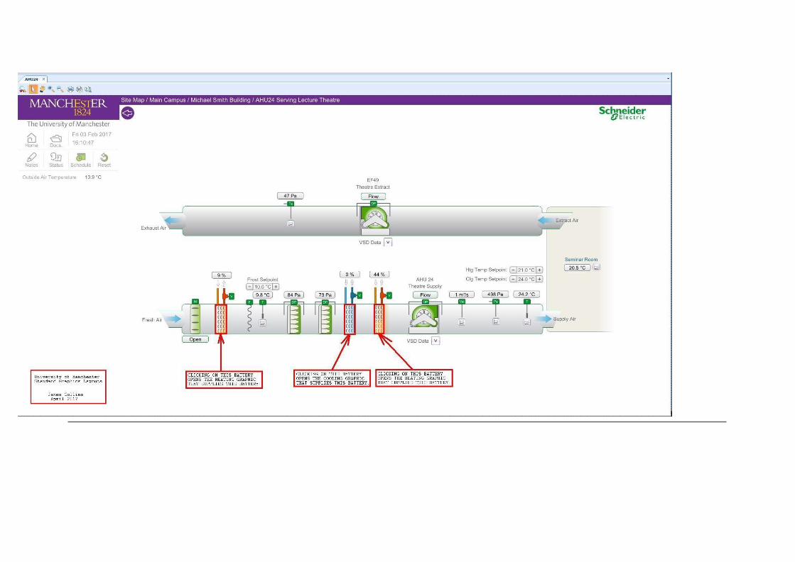


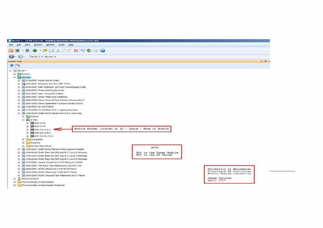


![Bericht zu PM10-Tagesmittelwerten und Überschreitungen …...28.04.2011 PM10 [µg/m³] 1 58 05.11.2011 PM10 [µg/m³] 5 62 12.11.2011 PM10 [µg/m³] 3 102 23.11.2011 PM10 [µg/m³]](https://img.dokumen.tips/doc/110x75/5feb2fd0c3ceb232dc68d90f/bericht-zu-pm10-tagesmittelwerten-und-oeberschreitungen-28042011-pm10-gm.jpg)