Embed Size (px)
Citation preview

A P P L I C A T I O N S G U I D E
Directional Sounderwith Voice Messaging

1
A P P L I C A T I O N S G U I D E
Directional Sounderwith Voice Messaging
Contents
Section 1: Introduction . . . . . . . . . . . . . . . . . . . . . . . . . . . . . . . . . . . . . . . . . . . . . . . . . . . . . . . . . . . . . . . . . . . . . . . . . . . . . . . . . . . . . . . . . . . . . . .2
Shortcomings of Traditional Methods . . . . . . . . . . . . . . . . . . . . . . . . . . . . . . . . . . . . . . . . . . . . . . . . . . . . . . . . . . . . . . . . . . . . . . . . . . . . . . .2
Directional Sound Aids Evacuation . . . . . . . . . . . . . . . . . . . . . . . . . . . . . . . . . . . . . . . . . . . . . . . . . . . . . . . . . . . . . . . . . . . . . . . . . . . . . . . . .2
Directional Sound Influences Human Behavior . . . . . . . . . . . . . . . . . . . . . . . . . . . . . . . . . . . . . . . . . . . . . . . . . . . . . . . . . . . . . . . . . . . . . . .3
Voice Messaging Aids in Guiding Occupants . . . . . . . . . . . . . . . . . . . . . . . . . . . . . . . . . . . . . . . . . . . . . . . . . . . . . . . . . . . . . . . . . . . . . . . .3
Section 2: Why Directional Sound Works . . . . . . . . . . . . . . . . . . . . . . . . . . . . . . . . . . . . . . . . . . . . . . . . . . . . . . . . . . . . . . . . . . . . . . . . . . . . . .4
Psychoacoustic Theory . . . . . . . . . . . . . . . . . . . . . . . . . . . . . . . . . . . . . . . . . . . . . . . . . . . . . . . . . . . . . . . . . . . . . . . . . . . . . . . . . . . . . . . . . . .4
Acoustic Performance in Building Applications . . . . . . . . . . . . . . . . . . . . . . . . . . . . . . . . . . . . . . . . . . . . . . . . . . . . . . . . . . . . . . . . . . . . . .4
Bandwidth . . . . . . . . . . . . . . . . . . . . . . . . . . . . . . . . . . . . . . . . . . . . . . . . . . . . . . . . . . . . . . . . . . . . . . . . . . . . . . . . . . . . . . . . . . . . . . . . . . . . .4
Sound Level Masking . . . . . . . . . . . . . . . . . . . . . . . . . . . . . . . . . . . . . . . . . . . . . . . . . . . . . . . . . . . . . . . . . . . . . . . . . . . . . . . . . . . . . . . . . . .5
Average Ambient Sound. . . . . . . . . . . . . . . . . . . . . . . . . . . . . . . . . . . . . . . . . . . . . . . . . . . . . . . . . . . . . . . . . . . . . . . . . . . . . . . . . . . . . . . . .5
Compatibility with Traditional Fire Alarm Notification Appliances . . . . . . . . . . . . . . . . . . . . . . . . . . . . . . . . . . . . . . . . . . . . . . . . . . . . .5
Compatibility with Voice Evacuation Systems . . . . . . . . . . . . . . . . . . . . . . . . . . . . . . . . . . . . . . . . . . . . . . . . . . . . . . . . . . . . . . . . . . . . . .5
Reverberant Building Environments . . . . . . . . . . . . . . . . . . . . . . . . . . . . . . . . . . . . . . . . . . . . . . . . . . . . . . . . . . . . . . . . . . . . . . . . . . . . . . .6
Section 3: Applicability of Building Codes and Standards . . . . . . . . . . . . . . . . . . . . . . . . . . . . . . . . . . . . . . . . . . . . . . . . . . . . . . . . . . . . . . . .6
Section 4: Locations for Directional Sounders . . . . . . . . . . . . . . . . . . . . . . . . . . . . . . . . . . . . . . . . . . . . . . . . . . . . . . . . . . . . . . . . . . . . . . . . . .7
What are the exits where directional sounders can be used? . . . . . . . . . . . . . . . . . . . . . . . . . . . . . . . . . . . . . . . . . . . . . . . . . . . . . . . . . .7
What are the areas of refuge or areas of rescue assistance where directional sounders can be used? . . . . . . . . . . . . . . . . . . . . .8
What are other means of egress components where directional sounders can be used? . . . . . . . . . . . . . . . . . . . . . . . . . . . . . . . .10
Locations that may not be suitable for directional sounders . . . . . . . . . . . . . . . . . . . . . . . . . . . . . . . . . . . . . . . . . . . . . . . . . . . . . . . . . .11
Section 5: Directional Sound Installations . . . . . . . . . . . . . . . . . . . . . . . . . . . . . . . . . . . . . . . . . . . . . . . . . . . . . . . . . . . . . . . . . . . . . . . . . . . . .12
General . . . . . . . . . . . . . . . . . . . . . . . . . . . . . . . . . . . . . . . . . . . . . . . . . . . . . . . . . . . . . . . . . . . . . . . . . . . . . . . . . . . . . . . . . . . . . . . . . . . . . . . .12
Type 1 (Basic) Installation . . . . . . . . . . . . . . . . . . . . . . . . . . . . . . . . . . . . . . . . . . . . . . . . . . . . . . . . . . . . . . . . . . . . . . . . . . . . . . . . . . . . . . . .12
Type 2 (Enhanced) Installation . . . . . . . . . . . . . . . . . . . . . . . . . . . . . . . . . . . . . . . . . . . . . . . . . . . . . . . . . . . . . . . . . . . . . . . . . . . . . . . . . . . .14
Special Considerations for Dead-Ends . . . . . . . . . . . . . . . . . . . . . . . . . . . . . . . . . . . . . . . . . . . . . . . . . . . . . . . . . . . . . . . . . . . . . . . . . . . . .18
Section 6: Positioning Directional Sounders on Wall and Ceiling Surfaces . . . . . . . . . . . . . . . . . . . . . . . . . . . . . . . . . . . . . . . . . . . . . . . .19
Section 7: Frequently Asked Questions . . . . . . . . . . . . . . . . . . . . . . . . . . . . . . . . . . . . . . . . . . . . . . . . . . . . . . . . . . . . . . . . . . . . . . . . . . . . . . .21
Section 8: Glossary . . . . . . . . . . . . . . . . . . . . . . . . . . . . . . . . . . . . . . . . . . . . . . . . . . . . . . . . . . . . . . . . . . . . . . . . . . . . . . . . . . . . . . . . . . . . . . . . .22
References . . . . . . . . . . . . . . . . . . . . . . . . . . . . . . . . . . . . . . . . . . . . . . . . . . . . . . . . . . . . . . . . . . . . . . . . . . . . . . . . . . . . . . . . . . . . . . . . . . . . . . . .23
List of Illustrations . . . . . . . . . . . . . . . . . . . . . . . . . . . . . . . . . . . . . . . . . . . . . . . . . . . . . . . . . . . . . . . . . . . . . . . . . . . . . . . . . . . . . . . . . . . . . . . . . .24

E X I T P O I N T ™ D I R E C T I O N A L S O U N D E R
This application guide pro-vides information to build-ing design professionals,
specifying engineers, fire alarm system installers, and enforcement authorities regarding 1) the technical or psy-choacoustic basis for directional sound technology, and 2) the implementation of directional sounders as an aid to locating exits, egress routes or refuge areas.
Directional sounders, integrated with the building’s fire alarm system, are a supplemental, audible means of iden-tifying exits and egress routes and can provide a means of overcoming the limitations of current exit signage and alarm signals. The directional sound from the devices does not conflict with the traditional audible alarm signals, whether horns or bells; however, they are not a substitute for these traditional fire alarm devices. (Directional sounders are NOT intended to replace or be a substitute for fire alarm system notification appliances.) There may be potential compatibility issues with the voice speakers for which guid-ance is provided in the following sections of the guide.
Shortcomings of Traditional MethodsFire alarm systems designed to initiate evacuation or relo-cation of occupants use audible and visible notification appliances that occupants will hear or see when the fire alarm system operates. Depending on the particular fire emergency plan, the occupants may be required to evacu-ate or relocate immediately or prepare for such evacuation or relocation. Oftentimes, occupants may not be familiar with the building and its associated emergency egress routes and may have to rely on exit maps, markings, or signage to guide them to an exit, refuge area or other means of egress.
The traditional maps, markings and signage required by codes provide occupants a visible means for locating or finding a path to safety. Generally, exit signage will be the primary means for locating an exit, refuge area or other means of egress. If an emergency plan has been prepared, it may include diagrams showing the locations and routes to exits. Occupants, however, may not have had an opportunity to study and understand such a diagram or cannot visualize an actual escape route as depicted on such a diagram.
There are other limitations to the way building occupants identify the means to reach a point of safety in a building during a fire or other emergency that necessitates evacua-tion or relocation. Persons with visual disabilities will have difficulty with emergency information that relies on visual cues. The signals that alert the occupants to an emergency event and suggest the need to evacuate usually are both audible and visual. Illuminated exit signs serve only as a visual cue. Other weaknesses are that the illuminated front of exit signs may often compete with nearby bright lights or other visually distracting elements. Exit signs may be inadvertently blocked from view due to renovations or remodeling of building or tenant spaces. Of course, at the time of a fire, when exit signs are most needed, it is possible for smoke to obscure exit signs and the location of exit doors.
Directional Sound Aids EvacuationDirectional sound technology offers a solution to improve the exit or relocation situation for building occupants. To help occupants in finding their way to an exit, refuge area or other means of egress, directional sounders integrated with the fire alarm system provide additional auditory information that can assist or aid occupants in locating escape routes without conflicting with the traditional fire alarm system notification appliances such as bells or horns. Directional sounders utilize a broadband acoustic characteristic that is distinctive from the audible sounds of bells, horns, or voice speakers. Directional sounders are intended to operate simultaneously with the traditional fire alarm notification devices and to be wired as part of the fire alarm system notification circuits. Again, it is important to note that directional sounders are NOT intended to replace or be a substitute for notification appliances required by building or fire codes. They are, however, to be installed on the notification appliance circuits, in accordance with NFPA 72, National Fire Alarm Code.
Experts and researchers in the area of human behavior have recognized two phenomena that appear common in evacuations of buildings.1,2,3 First, is that occupants tend to exit a building by the route familiar to them, which may be the same route they used to enter a building. Second is the concept of “learned irrelevance” of exit signs, where people continually exposed to exit signage seldom consider
Section 1
Introduction
Preface
This installation guide is the first effort of System Sensor to address the application of its new directional sounders for buildings and structures. The technology and initial applications of directional sound were developed at the University of Leeds under the supervision of Professor Deborah Withington and have become an accepted technology by international organizations as an aid to evacuation. While directional sound technology is a recognized and accepted technology over-seas, System Sensor considered it important and appropriate to obtain North American expertise to review the technology and assist with the development of this application guide. Experts with backgrounds in acoustic engineering, human behavior during fire and evacuations, building and fire codes; and fire protection engineering were key to this effort.
This guide intends to promote an understanding and awareness of the benefits and capabilities of directional sound. A primary focus of this guide is to provide information important to building design professionals, specifying engineers, fire alarm system installers, and enforcement authorities that will increase the probability of a proper installation and reduce the possibility of misapplication of directional sounders in the commercial marketplace. As with any new technology, it is anticipated that the role directional sound will play as a safety enhancement in buildings and structures will continue to develop and that this installation guide will be revised and updated to reflect modifications or improvements of the product features and refinements in directional sound applications in coming years.
February 2007
2
To support the development
effort for this guide and other
work, Schirmer Engineering
Corporation, serving as
the lead fire engineering
consultant, assembled a team
of experts that included both
in-house staff and several
key individuals recognized for
their particular expertise in
the areas of human behavior,
fire protection engineering,
and design of acoustic
environments. A special
thanks to the following for
their contributions to date:
John L. Bryan, DEd., Professor
Emeritus, Department of
Fire Protection Engineering,
University of Maryland, and
a student and observer of
human behavior in fire.
Guylene Proulx, Ph.D., Senior
Scientist, National Research
Council of Canada, and an
international expert on human
behavior in fires.
Robert P. Elfering, P.E., an
acoustical engineer with
Shiner & Associates, a
nationally recognized firm
specializing in acoustics for
commercial, multi-family,
residential, institutional,
educational, industrial and
recreational facilities.
Daniel J. O’Connor, P.E., fire
protection engineer. Vice-
President of Engineering for
Schirmer Engineering and the
Chair of the Society of Fire
Protection Engineer’s Task
Group on Human Behavior.
Member of the NFPA 72
Committee on Initiating
Devices.
The work of these individuals
serves not as an endorsement
of the technology, but
as independent sources
for validation of the
appropriateness of directional
sound and the identification of
limitations and considerations
in application.

S Y S T E M S E N S O RS Y S T E M S E N S O R
the information it is intended to convey, i.e. the identifica-tion of alternative exits and exit access. In an emergency, they fail to respond to signage pointing to alternate means of egress, instead opting for the exits with which they are familiar.
Directional sound offers a means for reducing these ten-dencies and providing an additional stimulus in the form of sound cues that draw attention to otherwise ignored egress routes and exit locations. In this way, directional sound can serve to increase exit utilization by encouraging the use of all exit facilities and speeding total evacuation when needed.
Directional Sound Influences Human BehaviorThe broadband sound pulses of directional sounders make use of our natural ability to localize sound sources when provided with the appropriate spectral and temporal cues. To be of benefit, the technology requires occupants to make use of these supplemental audible cues in a man-ner that enhances their behavior during an evacuation. The psychoacoustic response to directional sounders has been shown in numerous exercises and research studies to lessen the time required for evacuation and to effectively assist occupants searching for egress routes and exits. Numerous research studies have shown that directional sounders improve the flow of people towards exits, and they improve evacuation efficiency. While many of these realistic exercises were conducted on passenger ships and ferries, the results are broadly applicable to evacuation and relocation scenarios in buildings.
Prompted by a 1990 fire that resulted in 158 deaths aboard the Scandinavian Star ferry in Norwegian waters, numerous evacuation trials have been conducted by the
University of Leeds and the University of Strathclyde between 2000-2003. The various trials involved numerous scenarios such as evacuations with and without directional sound, evacuations with low visibility conditions created by use of theatrical smoke, and a variety of room and complex corridor arrangements. In smoke-filled scenarios with little or no visibility of exit signs, directional sound demonstrated its benefit to provide cues that significantly reduced the time for subjects to find the nearest exit and to find the exits without retracing their steps.
The egress behavior of subjects in normal visibility did not show the same extent of improvement in egress times, but subjects indicated the sound cue as a confirming aid in finding the exit. A more dramatic result was evident in evacuation trials when subjects received a briefing on the meaning of the directional sound. In these trials with brief-ings, the subjects consistently performed better at finding the closest exit and exhibited faster exit times.
Voice Messaging Aids in Guiding OccupantsA question often asked about directional sounders is how building occupants will know how to react when they hear the sound. Although the sound is intuitive to many peo-ple, an enhancement made to directional sound technology is the addition of voice messaging. In between four second bursts of directional sound, an alert message in the form of a recorded voice message can be used. The purpose of the voice message is to instruct the occupants of what action to take as they approach the directional sounder. This messaging will allow them to react quickly and confi-dently without training or prior knowledge of directional sound. The messages will instruct occupants that they are approaching stairs going up, stairs going down, an area of refuge, or the exit.
3

E X I T P O I N T ™ D I R E C T I O N A L S O U N D E R
Today, there is a signifi-cant body of literature and texts regarding the human mechanism of hearing and
the science of acoustics. Since approximately the 1980’s significant studies and technical work have been done to quantify and further understand the psychoacoustic mech-anisms that allow the human ear to pinpoint or localize the source of sounds.4,5,6,7 The following section summarizes the psychoacoustic basis for sound localization, describes why directional sound works and why directional sound is compatible with traditional fire alarm signals and reverber-ant building environments.
Psychoacoustic TheoryThe ability to pinpoint the location of a sound source is based on the physics of sound and the physiology of the human hearing mechanism. The brain processes a large amount of neural signals, some of which provide cues to the sound source’s location.
People are able to hear sound ranging from about 20 Hz to 20,000 Hz, although as we age this range diminishes. Many fire alarm signals are pure tones or narrowband sound
in the 1000 Hz to 3000 Hz range, to which the human ear is particularly sensi-tive as far as loudness is concerned. Unfortunately, pure tones in this frequency range provide only limited localization information.
The primary localization cues are provided by inter-aural time differences (lower frequencies), interaural intensity differences (mid to higher frequencies), and the head-related transfer func-tion (higher frequencies). In enclosed spaces that may be somewhat reverberant, the precedence effect provides directional information. Each of these four psycho-acoustic phenomena is dis-cussed briefly below:
The interaural time dif-ference (ITD) and inter-aural intensity difference (IID) are termed binaural cues because they depend on both ears separated by the width of the head. At lower frequencies (longer wavelength) the time delay between arriving sound sig-nals is detectable. Interaural time difference is most evi-dent in frequencies below about 1000 Hz with clicks or short bursts of sound. At higher frequencies (shorter
wavelength) the loudness/intensity differences between the ears is more noticeable because of partial shielding of the more distant ear by the head. Interaural intensity differences are most evident for frequencies above 3000 Hz. Figure 1 depicts the binaural cues – ITD and IID.
The head-related transfer function (HRTF) relies on the effect of the external ear on perceived sound. The HRTF describes the transforming effect of the head, torso and external ear on sound as it travels from the sound source to the ear canals. The shape of the ear attenuates some frequencies and amplifies others, filtering the sound field as depicted in Figure 2. This filtering effect is mainly due to directional reflection effects the pinna and concha of the outer ear have on the incident sound field. The HRTF changes depending on sound source location, provid-ing an additional localization cue. HRTF operates over a range of frequencies, but seems to be most effective in the 5,000 Hz to 10,000 Hz range. Combined with the listener’s head motion, HRTF provides an independent localization method to complement ITD and IID capabilities.
In addition to confirming ITD and IID localization cues, the HRTF provides vital localization information when the sound source is near the plane equidistant from each ear, i.e. directly in front, behind or above the head. In these situations ITD and IID do not provide distinct localization cues because each ear is equidistant and unshielded from the source. Front-back and vertical localization of the sound source is made possible by the HRTF.
The precedence effect is important for discriminating between the direct sound signal and reflected sound, a common situation within buildings. The ear is capable of discerning and fixating on the first sound received (line-of-sight direct signal) and disregarding later signals (reflected sound). The acoustical signal arriving first at the ears suppresses the ability to hear other signals (including reverberation) that arrive up to about 40 milliseconds after the initial signal.
All of the above cues are utilized simultaneously when the source signal is broadband sound containing a range of low and high frequencies. The combination of different cues provides reinforcement and redundancy of information to enhance the ability to locate the sound source. Broadband sound tends to eliminate potential ambiguities that occur for pure tone or narrowband sound sources.
For further information regarding the theoretical aspects of sound localization, see the list of sources in the enclosed reference section.
Acoustic Performance in Building ApplicationsThe directional sound device enables ready localization by providing bursts of broadband sound rather than a traditional pure tone signal. Intended to be used as a supplement to traditional alarm signals, a directional sounder provides an additional guidance cue. Parameters that account for the performance of directional sounders in buildings are as follows:
BandwidthBursts of directional sound cover a broad enough range to enable binaural localization cues and HRTF localiza-
Section 2
Why Directional Sound Works
Figure 1. Interaural time and intensity differences of sound.
Figure 2. Examples of frequency dependent attenuation for sources in front, above and behind the listener.
4

S Y S T E M S E N S O RS Y S T E M S E N S O R
tion cues. A low frequency content enables easy detection of interaural time differences, while a medium to high frequency content facilitates discrimination of interaural intensity differences. Low to high frequency content facili-tates discrimination using the HRTF.
Directional sounders contain frequency content extend-ing over almost all of the entire range discernible by the human ear. This wide band type of frequency content is often referred to as “white noise”. This wide spectral range of broadband sound is important for providing redundancy and reinforcement of perceived sound signals, enabling localization cues due to all binaural, transfer function, and precedence effect mechanisms.
Sound Level Masking The concept of “masking” is important when determin-ing appropriate sound pressure levels for alarm signals. Masking is an acoustic process in which the audibility of one sound (the signal) is affected by the presence of another sound (the masking sound). Masking sound, if it is loud enough and has similar frequency content, can partially or totally hide the signal sound.
Typical building environments have background noise due to ventilation and other mechanical systems, telephones, conversation, etc. In order to be clearly audible, the sound level of alarm signals should exceed background noise lev-els by at least 10 dB, preferably by 15 dB. The higher alarm signal level is required so that it is not hidden (masked) by other naturally occurring sound sources.
Average Ambient SoundAmbient sound levels should be determined in order that the sound levels of directional sounders can be set at appropriate sound levels. Figure 3 from Appendix A to NFPA’s Fire Alarm Code shows examples of what average ambient sound levels may be for different applications.8 The examples should not be used as a substitute to taking actual on-site measurements. In the same appendix, the following is stated regarding the measurement of average ambient sound:
“When surveying the ambient sound levels to establish the increased level at which a notification appliance will properly function, the sound source needs to be averaged over a longer period of time. Moderately priced sound level meters have such a function, usually called ‘Leq’ or ‘equivalent sound level.’ For example, an Leq of speech in a quiet room would cause the meter movement to rise gradually to a peak reading and slowly fall well after the speech is over. “Leq readings can be misapplied in situations where the background ambient noises vary greatly during a 24-hour period. Leq measurements should be taken over the period of occupancy.”9
Compatibility with Traditional Fire Alarm Notification AppliancesDirectional sounders are envisioned as an additional evacuation aid to be used with, not as a replacement for, traditional notification appliances (bells, horns and speak-ers). Hence, during the period that people are exiting or relocating, there will be two dominant alarm system sound sources, both of which should be audible.
Since both traditional alarms and directional sounders can comfortably exceed most common background nois-es, masking of alarm signals by ambient noise is not nor-mally an issue. Traditional alarm devices have a strong tonal content as opposed to the more even, broad-band content of a directional sounder.
Figure 4 compares the spectrum of a typical fire alarm signal at a high set-ting with the spectrum of the directional sounder at a lower power setting. Note that while the typical alarm signal clearly dominates at 3000 Hz and to a lesser extent at upper harmon-ics, the broadband direc-tional signal of the direc-tional sounder is 20-30 dB louder than the fire alarm over most of the range. And although the fire alarm may have an overall A-weighted sound level 20 dBA or more higher than the overall A-weighted sound level of the directional signal, both alarms are audible.
The reason that the direc-tional signal does not actu-ally have to be higher in overall sound pressure level than the traditional alarm signal is because the traditional alarm will only mask a narrow range of frequencies near the traditional alarm’s dominant pure tones. Since the directional sounder has a wide spectral range and is generated in short sound bursts giving timing, intensity and HRTF cues, most of the broad-band sound will be audible in the presence of higher pure tone sound levels.
Reverberant Building EnvironmentsDue to the precedence effect, the ear can discriminate the direct sound signal from reflected signals in enclosed spaces. The directional sounder’s pulsing broadband directional signal makes good use of the precedence effect and can compensate for less than optimum listening conditions. Even in highly reverberant spaces, in which every surface was sound reflective, test subjects have had no problem determining the location of directional sounders.
Most building interiors have a blend of sound reflective and sound absorbent finishes. However, even under the semi-reverberant conditions of certain building interiors such as gymnasiums and lobbies finished in concrete
Location Average Ambient Sound Level
Business occupancies 55 dBA
Educational occupancies 45 dBA
Industrial occupancies 80 dBA
Institutional occupancies 50 dBA
Mercantile occupancies 40 dBA
Piers and water-surrounded structures 40 dBA
Places of assembly 55 dBA
Residential occupancies 35 dBA
Storage occupancies 30 dBA
Thoroughfares, high density urban 70 dBA
Thoroughfares, medium density urban 55 dBA
Thoroughfares, rural and suburban 40 dBA
Tower occupancies 35 dBA
Underground structures and windowless buildings
40 dBA
Vehicles and vessels 50 dBA Figure 3. Typical ambient sound levels
5
Figure 4. Frequency response of traditional fire alarm signals versus
directional sounder
3 kHz Fire Alarm
Directional Sounder
Directional Sounder vs. Fire Alarm SignalDirectional sounder at 66dBA and fire alarm horn at 86dBAmeasured at 10 feet horizontally in an anechoic chamber
Frequency (Hz)

E X I T P O I N T ™ D I R E C T I O N A L S O U N D E R
1
Because directional sound-ers are wired as part of a building’s fire alarm sys-tem, the codes and stan-dards applying to fire alarm
installations also apply to directional sound. This is the case both when directional sound is added to existing fire alarm systems or when it is incorporated into new instal-lations. When an existing fire alarm system is altered to incorporate directional sound, it may be necessary to make other alterations or replacements so as to have the system conform to current standards.
The application of directional sound requires a basic understanding and knowledge of the means of egress, means of escape and area of refuge provisions found in the model codes for buildings and life safety. There are two independent organizations in the United States, the National Fire Protection Association (NFPA) and the International Code Council, Inc. (ICC), that write model building and fire codes intended for legal adoption by local governments (cities, counties, states). Local jurisdictions may adopt these model codes without change or alter them to suit their preferences. Some cities write their own codes, and many jurisdictions may still be operating under model codes promulgated by ICC predecessor organizations. The local authority having jurisdiction (AHJ) should be con-sulted for information on specific local regulations.
National Fire Protection Association (NFPA)Batterymarch Park, Quincy, Massachusetts 02169-7471
block, terrazzo, drywall, glass, etc., the sounder’s direc-tional signal will be easily locatable.
Compatibility with Voice Evacuation SystemsWhere directional sounders and voice evacuation systems employing speakers are utilized within the same occu-pancy the directional sounders can reduce the speech intelligibility of the voice speakers. For this reason it is recommended that when both systems are utilized in the same installation that the two systems are not operated simultaneously. Where simultaneous operation of the voice evacuation speakers and the directional sounders cannot be avoided there are system design guidelines that can be followed to reduce the effects of the directional sounders on the intelligibility of the voice speakers.
The factors influencing the loss to speech intelligibility include; the intelligibility of the voice system without the directional sounders operating, the amount of reverbera-tion present, and the sound pressure differential of the directional sounders vs. the voice speakers.
In general, if the speech intelligibility of the voice evacuation system before adding directional sounders is very good then the effects of the directional sounders will be minimized. Thus, improving the speech intelligibility of the voice sys-tem will minimize the loss from the directional sounders. This can be accomplished by using high quality speakers, using more speakers, and/or increasing the sound pressure of the voice system relative to ambient sound levels.
6
High degrees of reverberation will result in greater loss to intelligibility of voice systems when directional sounders are present. The degree of reverberation of a space will depend on the room characteristics such as the volume, the nature of finishes and furnishings and the number of occupants. Spaces with acoustically soft surface materials (textured ceiling tiles, drapes, carpet) will absorb sound and be less of a reverberant environment than spaces with acoustically hard surfaces (concrete, plaster, glass) which reflect sound around a space. To minimize the effects of the directional sounders, avoid using directional sounders in acoustically hard environments or reduce the sound pres-sure of the directional sounders in these areas. Sound pres-sure of the directional sounders can be reduced by either reducing the power setting of the sounders in the area or carefully selecting the locations of the directional sounders to increase the separation of the directional sounders and reverberant areas. If the reverberation in an area is too great it will not be possible to achieve good speech intel-ligibility even without the directional sounders.
In locations where the sound pressure of the voice system is comparable to the sound pressure of the directional sounders the reduction of intelligibility will be increased. In general, this will only occur in close proximity to the directional sounders. Speech intelligibility can be improved by adding additional speakers to these locations. This will increase the sound pressure of the voice system in these areas. In general, adding a second speaker will result in an increase of 3dB.
Section 3
Applicability of Building Codes And Standards
NFPA publishes codes and standards concerning all areas of fire protection. The key documents published by NFPA that define the requirements for exits and refuge areas are:
NFPA 101, Life Safety Code – NFPA 101 specifies the requirements for means of egress, means of escape and areas of refuge for new and existing buildings depending on the occupancy classification of a building or portion of a building.
NFPA 5000, Building Construction and Safety Code – NFPA 5000 is model building code for new construction that specifies the requirements for exits and refuge areas based on the occupancy classification of a building or portion of a building.
NFPA 1, Uniform Fire Code – NFPA 1 is a fire prevention code that incorporates provisions from prior editions of NFPA 1 and provisions of Western Fire Chiefs Association Uniform Fire Code. The document contains provisions for the means of egress and means of escape for new and existing buildings consistent with NFPA 101.
NFPA various other documents – Other NFPA documents may contain specific requirements for means of egress and means of escape.
Two other NFPA documents are of particular interest in relation to directional sounder installations:
NFPA 70, National Electrical Code – This is one of NFPA’s most widely recognized documents, covering all aspects of

S Y S T E M S E N S O R
electric wiring installations, including those for fire alarm systems. It has been adopted by ICC (see below) as part of its series of codes.
NFPA 72, National Fire Alarm Code – NFPA 72 covers all aspects of fire alarm installations, including detection devices, manual fire alarm stations, alarm notification devices, central station services, power supplies and arrangement of circuits. It has been adopted by ICC (see below) as part of its series of codes. The 2007 Edition of NFPA 72 provides guidance on installing and maintaining directional sounders in Chapters 6 (Protected Premises), Chapter 7 (Notification Appliances) and Chapter 10 (Testing and Maintenance.)
International Code Council, Inc. (ICC)5360 Workman Mill RoadWhittier, California 90601-2298The ICC is the successor organization to the three regional model code development organizations:
Building Officials and Code Administrators (BOCA)International Conference of Building Officials (ICBO)Southern Building Code Congress International (SBCCI)
The ICC was formed for the purpose of combining the above three organization’s codes into a single set of model building and fire codes. The first combined documents included the ICC’s 2000 International Building Code and 2000 International Fire Code, which define requirements for exits and refuge areas. Many jurisdictions have or are in the process of adopting the ICC’s building and fire codes, however, the BOCA National Building Code, the ICBO Uniform Building Code, and the SBCCI Standard Building Code continue to be used in many jurisdictions.
ICC documents that may contain exiting provisions or that may affect fire alarm (and directional sounder) installa-tions include:
• International Building Code• International Fire Code• International Existing Building Code• International Residential Code for One- and Two-
Family Dwellings• International Property Maintenance Code
• ICC Electrical Code – Administrative Provisions (adopts by reference NFPA 70)
• International Performance Code for Buildings and Facilities
Federal Accessibility Laws:Americans with Disabilities Act Accessibility Guidelines (ADAAG)Fair Housing Accessibility Guidelines (FHAG)In addition to any NFPA or ICC documents that may be legally adopted and applicable to building design are the Federal requirements applicable to buildings. The Americans with Disabilities Act (ADA) and the Fair Housing Amendment Act (FHA) are federal regulations that affect building construction as it relates to accessibil-ity for persons with disabilities. Exit design, refuge area design and fire alarm system design all are impacted by these federal laws.
Currently, NFPA and ICC documents address accessibility provisions for people with disabilities which are modeled on the requirements of the Americans with Disabilities Act Accessibility Guidelines (ADAAG) and the Fair Housing Accessibility Guidelines (FHAG). Compliance with NFPA or ICC documents, however, does not constitute compli-ance with federal requirements and designers are guided to review and understand both ADAAG and FHAG require-ments as they may apply to exit design, refuge area design and fire alarm system design. Additionally, it is noted that in the case of public service facilities (Title II of the ADA) an alternative design standard can be applied in lieu of the ADAAG. This standard is the Uniform Federal Accessibility Standards (UFAS).
Underwriters Laboratories, Inc. (UL)UL is a testing laboratory that evaluates components of fire alarm systems to verify compliance with NFPA requirements and their own standards. Equipment such as directional sounders that pass UL tests are identified by a label or listing. UL publishes an annual directory that lists equipment bearing the UL label. In the case of a directional sounder, the applicable test standard is UL 464, Audible Signal Appliances. Under this standard, a directional sounder is listed as a supplemental notification appliance.
What are the exits where directional sounders can be used?
Often, the simplest way to identify the exits in a building is to look for the exit signs. With few exceptions, exit signs will be found at the termination of exit paths, such as exte-rior doors at ground level, doors into enclosed stairways, doors leading horizontally into an adjoining building or fire area, and doors leading to exterior stairways and fire escapes.
The exit as defined by NFPA 101 (2003 ed.), NFPA 5000 (2003 ed.) and the 2003 ICC International Building Code is one specific travel element or section of the means of egress which is comprised of three distinct elements that are 1) the exit access, 2) the exit, and 3) the exit discharge. The exit is the primary focus of a basic installation of directional sounders, and most often this will be at doors
leading to the exterior, at doors into stairways, or at horizontal exit doors. Basic and enhanced installations are more fully described in the section of this guide entitled “Directional Sound Installations.” The three basic elements of the means of egress and the specific concepts of an exit passageway and a horizontal exit found in NFPA and ICC documents are described in the table on page 8.
Both code organizations use effectively the same concept in defining the exit. Figures 5 and 6 graphically illustrate the concepts of exit access, exit, and exit discharge.
The code definitions on page 8 provide the generic descrip-tion of an exit, which in more specific terms, may be found as one of the following types of exits described and illustrated below.• Doors leading directly to the outside at grade• Doors leading into a protected passageway which leads
to the outside at grade
Section 4
Locations for Directional Sounders
7

E X I T P O I N T ™ D I R E C T I O N A L S O U N D E R
EnclosedExit Stair
Exit AccessEnds at ExitDoor
up
dow
n
up dow
n
EnclosedExit Stair
X X
X
Exit Access StartsAt Any Point
X
X
X
Exit AccessRoutes
Figure 5. Exit access starts from any normally occupied point on a floor and ends at the door leading into an exit.
Exterior ExitStairway
Exit(From Grade Level)
Interior ExitStairway
Exit Discharge
Figure 6. Different types of exits illustrated.
• Interior stairs enclosed by fire rated construction, which includes – Smokeproof towers – Pressurized stairways
• Exterior stairs isolated from the building interior with fire rated or protective construction
• Passageways enclosed by fire rated construction (should not be confused with corridors)
• Horizontal exits• Ramps enclosed by fire rated construction• Escalators enclosed by fire rated construction• Fire escapes• Other special exits – Although the above listed items rep-
resent common types of exits found in buildings or struc-tures, there are other types of open or unenclosed routes that may legally constitute an exit. These are sometimes the result of unique building conditions, a code equiva-lency or performance-based building design.
Figure 7 illustrates one of the most common arrangements of an exit, the fire resistive enclosed stair. Figures 8 and 9 are enhanced versions of the same type of stair exit. Figure 8 illustrates a smoke-proof tower arrangement that repre-sents an enclosed stair preceded by an open-air balcony or vestibule. Similarly, Figure 9 shows an enclosed stair accessed via a vestibule that is mechanically ventilated.
What are the areas of refuge or areas of rescue assistance where directional sounders can be used?In 1990 the Federal Government passed the Americans with Disabilities Act which was the first large scale legislation to contain provisions for accessible means of egress for people with physical disabilities or mobility impairments, such as occupants using wheelchairs, walkers, crutches or canes. During the 1990s and up to the present time both the NFPA and ICC (and its predecessor organizations) have developed criteria for accessible means of egress consistent with the federal laws. In addition to federal law, both NFPA and ICC codes require that newly constructed buildings have accessible means of egress as defined by NFPA and ICC documents. An element of an accessible means of egress is often a specially provided space in the building
8
Basic Concepts – Means of Egress
NFPA Definitions ICC DefinitionsMeans of Egress – A continuous and unobstructed way of travel from any point in a building or structure to a public way consisting of three separate and distinct parts: (1) the exit access, (2) the exit, and (3) the exit discharge.
Means of Egress – A continuous and unobstructed path of vertical and horizontal travel from any occupied portion of a building or structure to a public way. A means of egress consists of three separate and distinct parts: the exit access, the exit and the exit discharge
Exit Access – That portion of a means of egress that leads to an exit. Exit Access – That portion of a means of egress that leads from any occupied portion of a building or structure to an exit.
Exit - That portion of a means of egress that is separated from all other spaces of a building or structure by construction or equipment as required to provide a protected way of travel to the exit discharge.
Exit - That portion of a means of egress that is separated from other interior spaces of a building or structure by fire-resistance-rated construction and opening pro-tectives as required to provide a protected path of egress travel between the exit access and the exit discharge. Exits include exterior doors at ground level, exit enclosures, exit passageways, exterior exit stairs, and horizontal exits.
Exit Discharge – That portion of a means of egress between the termination of an exit and a public way.
Exit Discharge – That portion of a means of egress system between the termination of an exit and a public way
Exit Passageway - NFPA does not maintain a formal definition of exit passageway but does explain the concept in the Appendix of NFPA101 as follows: An exit passageway serves as a horizontal means of exit travel that is protected from fire in a manner similar to an enclosed stair.
Exit Passageway – An exit component that is separated from other interior spaces of a building or structure by fire-resistance-rated construction and opening protectives, and provides for a protected path of egress travel in a horizontal direction to the exit discharge or the public way.
Horizontal Exit - A way of passage from one building to an area of refuge in another building on approximately the same level, or a way of passage through or around a fire barrier to an area of refuge on approximately the same level in the same building that affords safety from fire and smoke originating from the area of incidence and areas communicating therewith.
Horizontal Exit - A path of egress travel from one building to an area in another build-ing on approximately the same level, or path of egress travel through or around a wall or partition to an area on approximately the same level in the same building, which affords safety from fire and smoke originating from the area of incidence and areas communicating therewith.

S Y S T E M S E N S O R
up dow
n
Fire Door
Fire Rated EnclosedStairway
Figure 7. Fire-rated enclosed stair.
Fire Rating Based OnNumber Of Stories
up
down
up dow
n
Fire Rated Exit Passageway(Penetrations Restricted)
Corridor
Fire Rated Door
Figure 12. Floor exit arrangement showing a fire rated exit passageway leading to an enclosed exit stair. The doorway into the exit passageway constitutes the point of entry into the exit.
up dow
n
Fire Door
MechanicalVentilation
Shaft
Fire Rated EnclosedStairway
Figure 9. Smokeproof tower, mechanically vented.
2 Hour Fire Barrier Doors are Automaticor Self Closing Fire Doors
up
down
up
down
Enclosed ExitStair
Enclosed ExitStair
Figure 10. Building floor area served by enclosed exit stairs and horizontal exit fire barrier wall. Door openings through the 2-hour fire barrier qualify as exits.
9
8
7
6
5
4
3
2
1
6
5
4
3
2
1
Horizontal Exit from OneBuilding to Another Via Bridge
2 Hour FireBarrier WallEither orBoth Sides
Figure 11. Illustration of a horizontal exit using a bridge between two buildings.
9
Open to Outside
up dow
n
Fire Rated EnclosedStairway
Fire Door
Fire Door
Figure 8. Smokeproof tower.

E X I T P O I N T ™ D I R E C T I O N A L S O U N D E R
called an area of refuge. In fully sprinklered buildings, any sprinklered story or floor of the building is effectively con-sidered an area of refuge and; therefore, the areas of refuge discussed herein are typically found in recently constructed (i.e. buildings built after 1990) non-sprinklered, multi-story buildings. Buildings built prior to the passage of the Federal ADA laws typically are not required to have areas of refuge; however, state or local governments may have passed laws or ordinances that required areas of refuge in sprinklered and non-sprinklered buildings built before and after 1990.
Where areas of refuge have been designated, they typically will be a part of or immediately adjacent to a stairway that is part of the means of egress. As such, the direc-tional sounder at the entrance to the stairway will serve to identify the location of the area of refuge – see Figure 13, below. A different situation exists when an elevator serving as an accessible means of egress has been provided, and includes the elevator lobby as an area of refuge as shown in Figure 14. Such means of egress elevators and associated refuge areas are now required by ICC in non-sprinklered buildings having more than four levels above or below the level of exit discharge (the ground floor, usually), and they are permitted by NFPA. In such cases, a directional sounder must differentiate between access to an area of refuge solely intended for those requiring assistance for exiting and access to an exit stairway.
An unusual condition that may be encountered is where an elevator is also part of the required means of egress. This may occur in a tower structure, such as an airport traffic control tower. In these cases, the access to the elevator is treated in the same manner as access to a stairway, and a directional sounder at the entrance to the elevator lobby or the elevator door, itself, may be appropriate. Using eleva-tors as one of the recognized means of egress is likely to become more common in the future as codes are changed to reflect the reality of trying to evacuate tall buildings in an emergency.
What are other means of egress components where directional sounders can be used?In addition to exterior doors, doors leading to stairs and ramps, and other common components of the exits previ-ously identified, other types of exits and other components of the exit path may need directional sounders to assist in evacuation or relocation. In older buildings, fire escapes still are considered to be part of the required exit system, and they are likely to be identified by exit signs at the door or window leading to the fire escape, as well as in
Basic Concepts – Area of Refuge
NFPA Definitions ICC Definitions
Accessible Means of Egress – A means of egress that provides an accessible route to an area of refuge, a horizontal exit, or a public way.
Accessible Means of Egress – A continu-ous and unobstructed way of egress travel from any point in a building or facility that provides an accessible route to an area of refuge, a horizontal exit, or a public way.
Area of Refuge – An area that is either (1) a story in a building where the building is protected throughout by an approved, supervised sprinkler system and has not less than two accessible rooms or spaces separated from each other by smoke resisting partitions; or (2) a space located in a path of travel leading to a public way that is protected from the effects of fire, either by means of separation from other spaces in the same building or by virtue of location, thereby permitting a delay in egress travel from any level.
Area of Refuge – An area where persons unable to use stairways can remain tem-porarily to await instructions or assistance during emergency evacuation.
up
down
30 × 48 Wheelchair SpaceArea of RefugeAdjacent to Means ofEgress Stairway
48 M
inim
um
48 M
inim
um
up dow
n
Area of RefugeIn a Means ofEgress Stairway
48 Minimum
48 Minimum
Figure 13. Areas of refuge at stairways.
10
Accessible Elevator
X
up
dow
n
Exit Access Startsat Any Point
ProtectedArea of Refuge
X
X
Accessible ExitAccess Routes
up
down
Figure 14. Area of refuge at elevator lobby, serving an accessible means of egress elevator.

S Y S T E M S E N S O R
the corridor access to the fire escape. At both locations, directional sounders will be useful in supplementing the visual signage.
Exit access includes the path of travel from any point in the building along aisles and corridors to an exit. A Type 2 installation that provides sounders both at exits and in the exit access route is described in the section “Directional Sounder Installations,” following. Directional sounders in a Type 2 installation may be appropriate wherever supplemental signage is used to assist in identifying the exit access route.
Most commonly, supplemental exit signage (typically, an exit sign with or without single or bi-directional arrows) is used at corridor intersections where the direction to the exit is not obvious and for long stretches of corridors or walkways where the exit sign at the exit is too far away to be readily seen. Not all of these sign locations are appropri-ate for a sounder — sound is omnidirectional and travels around corners. Each potential sounder location has to be analyzed individually. Sounders spaced too closely may cause confusion. See “Directional Sound Installations” for guidance.
Open stairways (i.e. stairways not within a fire-resistive enclosure) and walkways, under certain circumstances, may also be designated as a primary means of egress and are likely to be designated by exit signs. Directional sound-ers may be appropriate at these locations.
“Dead-ends” and common paths of travel are other com-ponents of the means of egress. The former (see defini-tion, this page) can be a problem if a person becomes disoriented or fails to see an exit sign at the open end of a corridor that has only one way out. A directional sounder at the point where the “dead-end” corridor joins with paths to two (or more) exits will help to orient the occupant and lead the occupant away from a situation where the person can become trapped at the far, dead-end of the corridor.
Common paths of travel may include exit access travel in a dead-end corridor, but the most common situation is the travel from any point in a room to the room’s only door. Because two separate paths to an exit are not available within the room, that portion of the means of egress is a common path of travel. The codes limit the length of such common paths of travel, depending on the occupancy. In complicated situations, as for instance, when the space is broken up by filing cabinets, library shelving or other such obstructions, a directional sounder at the room’s exit door will better define the way out than an illuminated exit sign. Even though under such conditions an exit sign may be required only if the room is intended to be occupied by more than 50 persons, a sounder can be appropriate even for space intended for fewer than 50 persons, such as a library stack area.
Locations that may not be suitable for directional soundersUnder some circumstances, windows may be designated as an emergency means of escape. In schools and day care centers, they are designated as “windows for rescue,” intended to be used by firefighters to assist in evacuation, but not by the children on their own. In such locations,
Other Means of Egress Features
NFPA Definitions ICC Definitions
Common Path of Travel – The length of travel measured in the same manner as travel distance but terminating at the point where two separate and distinct routes of travel become available. Separate paths that merge also are common paths of travel.
Common Path of Egress Travel – That portion of exit access which the occupants are required to traverse before two separate and distinct paths of egress travel to two exits are avail-able. Paths that merge are common paths of travel.
Dead-End Corridor – (commentary) A condition where the corridor continues past an exit and cre-ates a pocket into which an occupant might travel. Relatively short dead-ends are generally permitted.
Dead-End Corridor – not defined; assumed to be self-explanatory. A maximum dead-end cor-ridor length of 20 feet is permitted.
Dead-End Corridor
up dow
n
up
dow
n
Enclosed Exit Stair
Figure 15. Dead-end corridor
Exit
Common Path of Travel
X
Dead-End
Exit
Figure 16. Common path of travel
11
sounders would serve no practical purpose. Windows designated for escape also may be encountered in apart-ments and private residences, where sounders would not be appropriate.
Sounders are not appropriate under other circumstances. A stairway may stop before it reaches a point where it dis-charges to a place of safety, instead discharging back into the building at a point that can be involved in fire or filled
E X I T P O I N T ™ D I R E C T I O N A L S O U N D E R
with smoke. Elsewhere in a building, an exit door or stair-way may not be accessible because there is an intervening door that might be locked. An exterior door that appears to lead to a place of safety actually leads to an outdoor enclosed space from which there is no escape. The build-ing codes do not allow such doors or stairs to be consid-ered as exits, and typically, there would be no exit signage in connection therewith. But mislabeling can occur, and changes are made to buildings without a complete review of the means of egress. It is possible for an exit sign to be improperly placed at a door or stairway that does not lead to safety, and placing directional sounders at such loca-tions must be avoided. (It should be noted that both NFPA and ICC documents permit ground-level discharge from a stair back into the building under prescribed conditions. In these cases the stair is consider a viable exit and should be marked accordingly as an exit)
Portable ladders, rope fire escapes and similar escape devices, according to appendix material in the NFPA Life Safety Code, can be useful to facilitate escape from a burn-ing building but may be unsuitable for use by aged or disabled people or by small children. Neither NFPA nor ICC recognizes these as legitimate exits, and directional sound-ers should not be used to identify their location.
For new buildings, particularly, both NFPA and ICC state that access to an exit shall not pass through a high-hazard occupancy, a kitchen, a storeroom or a closet. It is com-mon, however, to find the second means of egress from a restaurant dining room to be through the kitchen, and there may be other circumstances where such “prohibited” means of egress are permitted. When such situations are encountered, the authority having jurisdiction should be contacted for the appropriateness of sounders at these apparent exit access paths.
12
General General guidance is provid-ed in this section for direc-tional sound installations
for either new fire alarm systems or as enhancements to existing systems. Installation and maintenance instructions for the directional sounders provided by the manufacturer and NFPA 72 should be consulted for specific information related to mounting, device features, electrical wiring and appropriate settings.
Directional sound is a broadband, multi-frequency sound. A directional sounder should incorporate the capability to be set to multiple pulse patterns, each consisting of a period of directional sound interleaved with an optional voice message. The patterns are used to provide distinc-tive sound cues at an exit or along a route to the nearest exit and the voice messaging provides clear instructions to building occupants.
The pulse patterns can be set to signify increasing proxim-ity to an exit, the fastest pulse being used at the exit. Other audible information can supplement the pulsing broad-band sound as guidance. For example, each pulse pattern is capable of being supplemented with other audible cues such as voice messaging instructing occupants that they are approaching a stairway going up or down, or that they have reached an exit. Another direction given is that occupants are approaching an area of refuge, which should be distinctly marked.
The application or installation of directional sounders in buildings or structures requires an understanding of basic egress concepts and features. Key concepts and features that are important considerations in developing and imple-menting an installation of directional sound devices have been reviewed and, again, are as follows:
• Exit access• Exit• Exit discharge• Refuge area, area of refuge, or area of rescue assistance• Horizontal exit• Exit passageway• Dead-end corridor• Common path-of-travel• A fire escape when recognized as an exit
The concepts used to position directional sounders differ from the concepts applied to standard notification appli-ances (See System Sensor “Audible/Visible Appliance Guide”). Generally, fire notification appliances in build-ings, such as bells, horns and speakers, require placement at numerous locations in order to achieve the sound levels that can be heard and understood by occupants throughout all building areas. NFPA 72 would consider this a “public mode” application.
A symbol different from the traditional fire alarm devices should be used for directional sounders on installation floor plans. The following symbol is used in this guide and is suggested for general usage:
Figure 17. Directional sounder icon
Type 1 (Basic) InstallationA Type 1 installation calls for directional sound devices at the location of code-required exits and areas of refuge. The intent is to place a directional sound device in close proximity to the door of each exit or area of refuge as an audible cue for locating it in an emergency.
Examples of Type 1 installations are shown in Figures 18 through 20.
In a Type 1 installation of directional sounders, the concern is not for establishing an audible signal in all occupied building spaces. Rather, the focus is to provide sound cues to assist occupants in more easily locating the point of entry to an exit or area of refuge during an evacuation and under possibly smoky conditions. The key considerations for establishing a Type 1 installation are as follows:
• Using the guidance in the section “Locations for Directional Sounders,” identify the doors leading to exits and areas of refuge. Also, identify areas where directional sounders should not be used.
• Determine the position of directional sounders based on the recommended installation zones for doors, using the guidance in the following section “Positioning Directional Sounders on Wall and Ceiling Surfaces.”
Section 5
Directional Sound Installations
S Y S T E M S E N S O R
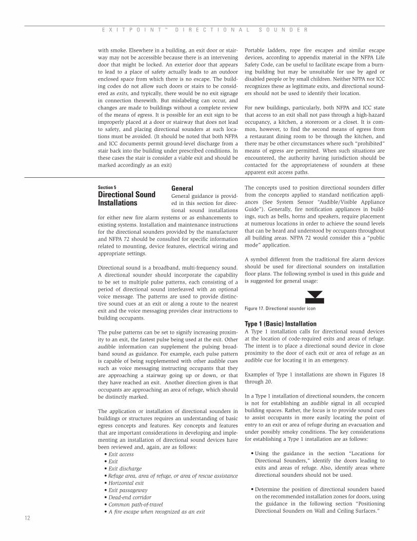
• Determine the ambient sound levels for the location of each exit or area of refuge door. Specify the power set-ting that will result in a minimum 15 dBA sound level above ambient sound levels at ten feet from the device. Power settings resulting in a sound level in excess of 15 dBA above ambient are acceptable where greater sound level penetration is desired.
• Directional sounders located at exit doors are set to the fastest pulse pattern and may the incorporate the voice message “Exit Here.”
• Directional sounders located at stairwells are set to the fastest pulse pattern and may incorporate the voice messages “Stairs Up” or “Stairs Down”, depending on the orientation to ground level.
• Directional sounders located at doors leading to exit stairs that also have an area of refuge at or adjoining the landing are set to a fast pulse pattern, followed by the distinctive “area of refuge” supplemental indicator.
EnclosedExit Stair
EnclosedExit Stair
up
dow
n
updow
n
Area ofRefuge
Area ofRefuge
Sounder Set to ‘Fast’ Pulse PlusRefuge Tone to Mark Entranceto Exit Stair and Adjoining Areaof Refuge
Sounder Set to Fast’ Pulse to
Mark Exit Stair
Sounder Set to ‘Slow’ PulsePlus Refuge Tone to Mark Areaof Refuge That is Not an Exit
KEYExit Sign Shaded QuadrantRepresents Visible Face
Exit Sign With Designationof Directional Arrow
Directional Sounder
Full Height Walls
Partial Height Dividers
Figure 18. Directional sounders at exit stairways and areas of refuge in a Type 1 installation.
up
up
down
down
Common Path of Travel
Dea
d-En
dD
ead-
End
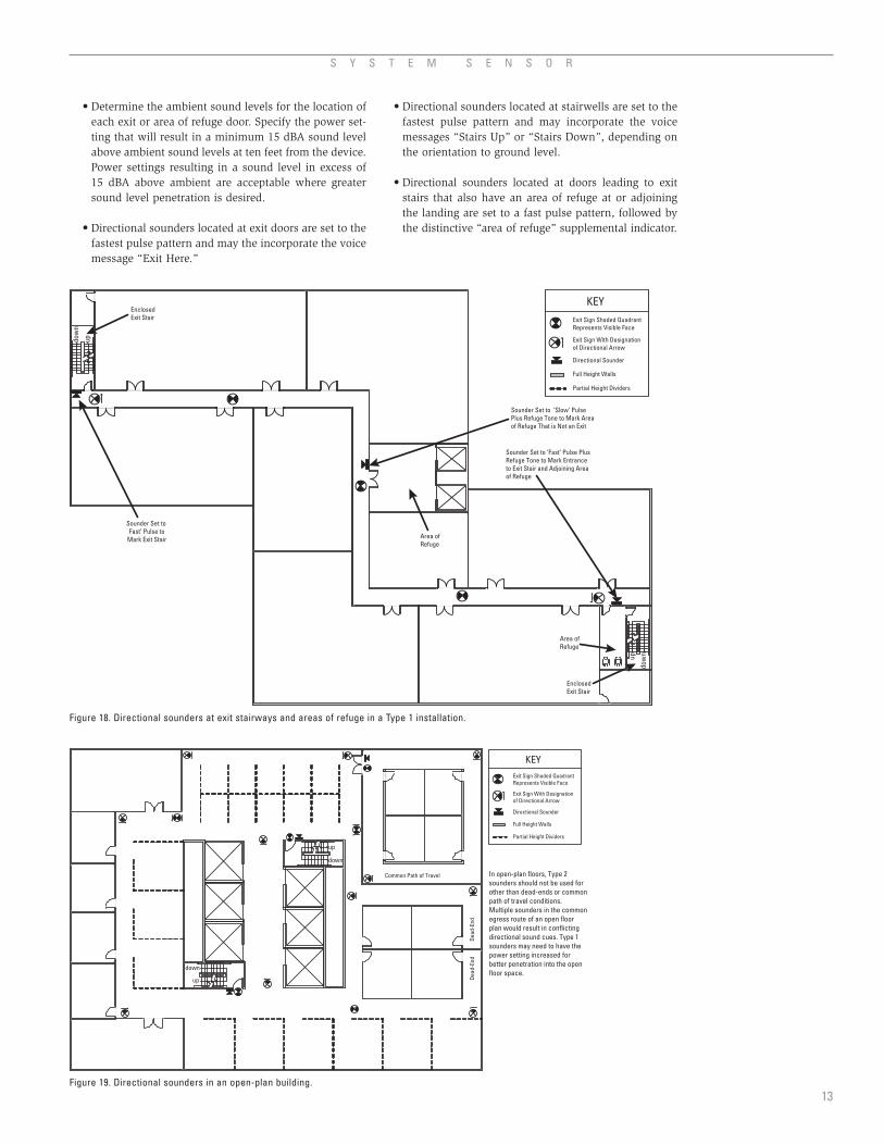
In open-plan floors, Type 2sounders should not be used forother than dead-ends or commonpath of travel conditions.Multiple sounders in the commonegress route of an open floorplan would result in conflictingdirectional sound cues. Type 1sounders may need to have thepower setting increased forbetter penetration into the openfloor space.
KEYExit Sign Shaded QuadrantRepresents Visible Face
Exit Sign With Designationof Directional Arrow
Directional Sounder
Full Height Walls
Partial Height Dividers
Figure 19. Directional sounders in an open-plan building.13

E X I T P O I N T ™ D I R E C T I O N A L S O U N D E R
• In some cases, it may be beneficial to use additional directional sounders prior to the location of the exit where intervening doors occur along the egress path, such as cross corridor doors which are self-closing or automatic closing. When such intervening doors significantly reduce the penetration of the directional sounder mounted at the exit along the egress pathway an additional sounder installed at the intervening doors will provide a sound cue for occupants seeking the exit located beyond the intervening doors (see Figure 20).
• A building’s emergency planning documents, includ-ing occupant training procedures, should be revised to reflect the meanings of the “slow” and “fast” pulse directional sounds and the supplemental signals.
Type 2 (Enhanced) InstallationA Type 2 installation is an enhanced Type 1 installation. In addition to the sounders needed for a Type 1 installation, it provides devices that give audible directional cues at key points along the means of egress, thereby guiding the person towards the exit or area of refuge. Locations to be considered for supplemental directional sounders in a Type 2 installation include the following:
• door from a room/area having a common path-of-travel,
• the outlet end of a dead-corridor,• at points of multiple route choice where a directional
sound device is located leading in the direction of the nearest exit,
• at points along a route where the sounder at the exit is not audible. In this case a directional sounder is installed to act as a locator of the egress route to the exit.
Care must be taken in a Type 2 installation to guide the person in just one direction, generally the direction that leads to the closest exit. Situations that can lead a person into a circular route or into a dead-end must be avoided. A Type 2 installation requires additional analysis effort and design specification to properly implement directional sounders. The key considerations for establishing a Type 2 installation are as follows:
• Include all directional sounders necessary for a Type 1 installation.
• Use additional directional sounders where they will enhance the ability of occupants to locate exits and the direction thereto. When locating a directional sounder at a point where the egress path turns or changes direction, preferably locate the sounder past the turn but no further than approximately 2 feet past the turn. It is also acceptable to locate the sounder just before the turn. See Figure 21 for the recommended zone for locating sounders at turns in the egress route such as a corridor.
• In some cases, it may be beneficial to use additional directional sounders where intervening doors are located along an egress path such as cross corridor doors which are self-closing or automatic closing. When such intervening doors significantly reduce the penetration of directional sound along the egress path-way an additional sounder installed at the intervening doors will provide a sound cue for occupants following the egress route that continues beyond the intervening doors. (See Figure 22.)
14
Fire Rating Based onNumber of Stories
up
down
up dow
n
CorridorSet DirectionalSounder to ‘Fast’Pulse Pattern
Intervening Door
Additional sounder set to ‘Fast’ pulse to increase the directional sound penetrationinto the corridor once the intervening door closes. The sounder should be locatedon the corridor side of the door. Once the evacuees pass through the door they willbegin to hear the sounder at the stairwell and proceed towards the actual exit.
Figure 20. Floor exit arrangement showing a corridor leading to an enclosed exit stair. Example indicat-ing when directional sounders should be placed at an intervening door.
2 FT.
Direction of Travel tothe Nearest Exit
Center Line of Corridor
PreferredInstallationZone
AcceptableInstallation Zone
Direction of Travel tothe Nearest Exit
Figure 21. Preferred and acceptable zones for location of directional sounders at a turn in the exit access route.

S Y S T E M S E N S O R
15
Enclosed Exit Stair
up
down
‘Fast’ Pulse
‘Medium 1’ Pulse
‘Medium 2’ Pulse
‘Slow’ Pulse
KEY
Directional Sounder
Full Height Walls
Partial Height Dividers
Figure 23. Level 2 sounders in a long corridor, with slow to fast pulse patterns along the exit access route towards the exit.
Enclosed Exit Stair
up
down
‘Fast’ Pulse
Location B‘Medium 1’ Pulse
Location A‘Medium 2’ Pulse
‘Slow’ Pulse
For an intervening door close to a sounder, anadditional sounder before the door may not benecessary. An appropriate alternative would berelocating the sounder from location B aheadof the door.
The intervening doors, when closed, are likely to reduce the soundpenetration of the sounder at location A. Therefore, an additionalsounder would be appropriate before the intervening doors. Inthis case the sounder mounted before the doors would be set to a‘Medium 2’ pulse the same as the sounder at location A.
RelocationAlternative
KEY
Directional Sounder
Full Height Walls
Figure 22. Building floor area served by enclosed exit stairs with intervening doors along egress route. Example indicating when additional directional sounders may be necessary at intervening doors.
• Use increasing speed in pulse patterns in moving from sounder locations most distant from the exit (slower pulse) to sounders nearer the exit (faster pulse). (See Figure 23.)

E X I T P O I N T ™ D I R E C T I O N A L S O U N D E R
Enclosed Exit Stair
up
down
‘Fast’ Pulse
‘Medium 1’ Pulse
‘Medium 2’ Pulse
‘Slow’ Pulse
‘Medium 2’ Pulse
Same Pulse OK If NotSame Route to Exit
Not More Than FourSounders Along SameRoute to Exit
KEY
Directional Sounder
Full Height Walls
Figure 24. Sounders in a Type 2 installation in a long, complex exit access route.
Key DecisionPoint
Key DecisionPoint
Rout
e A
Exit Exit
Exit
Considerations for Occupant Load Balance:Although Route A is the shortest traveldistance to an exit, Type 2 sounders are notrecommended to be located along Route Adue to the limited exit capacity. Whereoccupant balance issues may be present, itis recommended that directional soundersbe limited to a Type 1 installation (exits only).
Auditorium(400 Occupants)
KEYExit Sign Shaded QuadrantRepresents Visible Face
Exit Sign With Designationof Directional Arrow
Directional Sounder
Full Height Walls
Figure 25. A Type 2 installation should not be used where supplemental sounders may not lead to the most appropriate exit.
• Do not use more than four sounders in the route towards an exit. Only four pulse patterns are available (including that of the Type 1 sounder at the exit), and using two sounders with the same pulse patterns along the same route may cause confusion on the direction to the nearest exit. (See Figure 24.)
• Use a maximum separation of 50 to 80 feet between sounders along the egress path. In general, direc-tional sound pressure will reduce by 6dB for every doubling of distance. In high sound absorbing locations the maximum separation between direc-tional sounders may need to be reduced. As indi-
16
cated in Figure 28, sound pressure levels will drop to an ambient level at a distance of approximately 56 to 100 feet for sounders set to a sound pressure level of 15 to 21 dB above ambient (measured at 10 feet from device), respectively. As a general rule spacing sounders in the range of 50–80 feet apart will provide readily identifiable sound cues as occupants move through exit routes. Such spacing will result in occu-pants approaching the audible zone of the directional sounder within several steps after passing a previous sounder location.
• Use Type 2 sounders in rooms or spaces having an open floor plan with a single means of egress that constitutes a common path of travel.
• A building’s emergency planning documents, includ-ing occupant training procedures, should be revised to reflect the meanings of the “slow” and “fast” pulse directional sounds and the supplemental signals.
A Type 2 installation is not always appropriate:
• Do not use a Type 2 installation for open floor plans with multiple exits, where sounders will tend to con-flict with each other.
• Do not use a Type 2 installation where occupant loads and exit capacities are not reasonably balanced with travel distances to routes. (See Figure 25.)
Additional illustrations of Type 2 installations can be found in Figures 26 and 27.

S Y S T E M S E N S O R
17
EnclosedExit Stair
updow
n
EnclosedExit Stair
up
dow
n
Sounder Set to‘Fast’ Pulse toMark Exit Stair
Sounder Set to FastPulse to Mark Exit Stair
Corridor A
Corridor C
Corr
idor
B
No directional sounder is neededin corridor with alternativedirections of movement
Directional sounder is located in Corridor C inproximity of exit sign; intent is to provide soundcue outside Corridor B leading to direction ofexit stair. Sounder set to ‘Medium 1’ pulse.
Directional sounder is located in Corridor A inproximity of exit sign; intent is to provide soundcue outside Corridor B leading to direction ofexit stair. Sounder set to ‘Medium 1’ pulse.
Suite with CommonPath of Travel
Directional sounder is located toProvide sound cue of location ofSuite egress door. Sounder set to‘Medium 2’ pulse (optional if corridorSounders are not audible).
KEYExit Sign Shaded QuadrantRepresents Visible Face
Exit Sign With Designationof Directional Arrow
Directional Sounder
Full Height Walls
Partial Height Dividers
Figure 26. Example of a Type 2 installation.
Key decision points should beidentified as locations fordirectional sounders. Thesounders are located on theside of the exit signs that isnearest an exit.
up
down
up
down
Key egress decision point. For Type 2 installation locatedirectional sounder in direction of nearest exit.
Decision point with 4 egressrouite choices. Directionalsounder is not recommendedin these nearby corridorareas to avoid conflictingsound cues.
Key Decision Point
Key Decision Point
Key Decision Point
A
CBSounder placed at this
location so that buildingoccupants originatingfrom points A, B, or C willfollow theshortestpath toan exit.
KEYExit Sign Shaded QuadrantRepresents Visible Face
Exit Sign With Designationof Directional Arrow
Directional Sounder
Full Height Walls
Figure 27. A Type 2 installation with multiple egress route decision points.
Directional sounders are at exit stairways and at key egress route changes. Sounders in the corridor along the exit access route are needed if the directional sounders at the stairways are not audible.

E X I T P O I N T ™ D I R E C T I O N A L S O U N D E R
Special Considerations for Dead-EndsFigures 29 and 30 illustrate common types of dead-end cor-ridor conditions. In each case, when a directional sounder is used in a Type 2 installation, it should be located fully outside the dead-end corridor, such that a person will be directed out of the dead-end and towards the nearest exit. No sounder should be placed within the dead-end portion of the corridor as it may draw persons outside the dead-end into the dead-end condition.
The shaded portions on the diagrams (Figures 29 and 30) give the preferred location of Type 2 sounders in each
instance. To guide the occupants in the proper direction, the sounder should be placed into the access route to the nearest exit, past the dead-ends by not more than two feet. It can be either wall or ceiling-mounted. Once past this sounder, they should hear a more rapidly pulsed sounder in the direction of the exit.
The Type 2 sounder at the end of a dead-end corridor may be unnecessary if either the Type 1 sounder at the nearest exit or another Type 2 sounder in the exit access route is close by and readily audible at the far end of the dead-end.
up
down
Dead-End
2’
Exit Stair
Path toAlternate Exit
Path toNearest Exit
* Not needed if sounder at stairwayis audible at far end of dead-end.
Locate Type 2DirectionalSounder Here*
KEY
Directional Sounder
Full Height Walls
Figure 29. Directional sounder at single dead-end corridor.
Dead-EndCorridors
No Sounder
No Sounder
No Sounder
Path to Exit
2’
Type 2 DirectionalSounder Location
KEY
Directional Sounder
Full Height Walls
Figure 30. Directional sounder at multiple dead-end corridors.
Sound Pressure vs. Distance from Directional Sounder
–5
0
5
10
15
20
25
10 20 30 40 50 60 70 80 90 100
Distance from Sounder (Feet)
Soun
d Pr
essu
re a
bove
am
bien
t (dB
)
Figure 28. Sound pressure of directional sound compared to ambient as a function of distance from the directional sounder.
Note: Initial sound pressure of directional sound set at 15dB, 18dB and 21dB greater than ambient at 10 feet.
18

S Y S T E M S E N S O R
A directional sounder should be installed in close proximity to the location of a door or multiple doors that provide the initial entry
point into or through the exit or area of refuge. In the case of smoke-proof towers or exit passageways that lead to an enclosed stair, the initial entry point is the first door encountered in the path into the smoke-proof tower or into the exit passageway. The following figures illustrate recommended zones for locating directional sounders on
the wall or on a ceiling in cases where sufficient wall space for mounting a device is not available.
In the case of open floor plans, partial-height partitions can pose a sound absorbing obstruction to a directional sound device. The directional sounder shall be placed above the level of room dividers, preferably one to two feet higher. Figure 36 illustrates the desirable distance that a direction-al sounder should be installed above the highest partition, or divider, in the space.
Additional sounders may be needed at multiple arrays of multiple doors, based on sound pressure.
Floor
Door HandleHeight
CeilingCenter Line of
Door
EXIT
12 in.
24 in.
Hatch Area isPreferredZone forLocation ofDirectionalSounders
Hatch Area isAcceptableZone forLocation ofDirectionalSounders
ExampleLocations forDirectionalSounders
ExampleLocations forDirectionalSounders
Single Door
Figure 31. Sounder locations adjoining a single door.
Floor
Ceiling
Center Line ofDoor
EXIT
12 in.
24 in.
Hatch Area isRecommendedZone forLocation ofDirectionalSounders
ExampleLocations forDirectionalSounders
Double Door
Figure 32. Sounder locations adjoining a double door.
Floor
Ceiling
Center Lineof Device
2 ft.
Where limitedwall surfacesare available, aceiling mountinstallationwith directionalsounder no morethan 2 feet distanceoff face of door.
ExampleLocationsforDirectionalSounders
Side View
Floor
Ceiling
Front View
Figure 33. Ceiling-mounted sounders.19
Section 6
Positioning Directional Sounders on Wall and Ceiling Surfaces

E X I T P O I N T ™ D I R E C T I O N A L S O U N D E R
Where Directional Sounders Are Orientedtoward a space with partial height dividersit is recommended that the directionalsounder be above the top of tallest divideror partition.
24 in.
Directional Sounder
Side View
Floor
Ceiling
EnclosedExit Stair
60 in.
Desirable
Figure 36. Sounder location above level of room dividers.
Floor
Center Line ofDoor Array
EXIT
36 in.
24 In.
Hatch Area Is RecommendedZone for Location ofDirectional Sounders
Example Locations forDirectional Sounders
Door Array – Recommended Locationfor Multiple Door Installation
EXIT
36 in.
Figure 34. Sounder locations at multiple doors.
Wide Corridor
Center Line of DoorArray
36 in.
24 in.
Hatch Area is RecommendedZone for Location ofDirectional Sounders
Example Locationsfor DirectionalSounders
Where egress approach is from one direction, the directional soundershould be located over both sets of doors encountered.
36 in.
EXIT
Example Separation of 6 ft.Separation May Be Larger
Wall EndsDirection OfEgress Approach
Center Line of DoorArray
36 in.
24 in.
Hatch Area is RecommendedZone for Location ofDirectional Sounders
Example Locationsfor DirectionalSounders 36 in.
EXIT
Figure 35. Sounder location at single-directional approach to multiple doors.
20

S Y S T E M S E N S O R
1. What is a directional sounder and how does it work?A directional sounder is a
type of electronic signaling device that is installed as part of a building fire alarm system. When activated, it produces short bursts of broadband sound in a frequency range that is distinctive from the audible sounds of bells, horns, or voice speakers. The broadband sound pulses of directional sounders make use of our natural ability to localize the sound sources.
2. What does the term “Directional” refer to?The term “directional” refers to the unique characteristics of the sound that allow listeners to identify exactly where the sound is coming from. It does not in any way refer to the orientation or direction that the sound emanates from the sounder.
3. What is the advantage of adding directional sound-ers to a building’s emergency egress facilities?Directional sound technology offers a solution to improve the exit or escape situation for building occupants. To help occupants in finding their way to an exit, refuge area or other means of egress, directional sounders integrated with the fire alarm system provide additional auditory information that can assist or aid occupants in locating escape routes without conflicting with the traditional fire alarm system notification appliances such as bells, horns, or voice speakers. Directional sounders effectively serve as “audible exit signs.” They are installed at exits and at points in between as an additional cue for persons needing to find exits and areas of refuge in an emergency. Because sound travels around corners, directional sounders are not line-of-sight dependent, and their unique audibility is an assist for persons with visual impairments.
4. What activates and powers the directional sounders?Directional sounders are wired into and powered by the alarm notification circuits of the building’s fire alarm sys-tems. Directional sounders are intended to operate simulta-neously with the traditional fire alarm notification devices and to be wired as part of the fire alarm system notification circuits. There is no need to have a separate control panel for directional sounders.
5. Can directional sounders be installed as part of any fire alarm system?Directional sounders should be compatible with the man-ufacturer’s recommended power supplies for the fire alarm system in which the sounders are used. Additional power supplies may be needed to handle the added current draw of the directional sounders.
6. What is a Type 1 (basic) directional sounder installation?A Type 1 (basic) directional sounder installation is focused on providing directional sounders only at “exits” and “areas of refuge” as defined by building and fire codes. Such an installation typically includes a sounder at exte-rior exit doors, at doors leading into enclosed stairways or ramps, at the entrance to areas of refuge, at horizontal exit
doors, and at other points defined as an “exit” or “area of Refuge” by applicable codes or standards.
7. What is a Type 2 (enhanced) directional sounder installation?A Type 2 installation is an enhanced Type 1 installation. In addition to the sounders needed for a Type 1 installation, it provides devices that give audible directional cues at key points along the means of egress, thereby guiding the person to a nearby exit or area of refuge. In a Type 2 instal-lation additional directional sounders can be used to mark the direction away from a dead-end corridor situation or identify the single means of egress from a room or space.
8. Are all installations either Type 1 or Type 2?Type 1 installation refers to an installation that locates directional sounders only at the exits. Type 2 installation refers to an installation that includes additional sounders throughout the egress pathways. There may be situations where a Type 1 installation is desired, however due to spe-cial situations, some additional sounders may be required. An example of a special situation might include the case where locating sounders only at the exit may not provide adequate sound penetration to reach the majority of the occupants. These installations may not be considered Type 2 installations since the objective isn’t to identify the entire egress pathway even though additional sounders are used.
9. How many directional sounders are needed in a building?Just as the numbers of traditional fire alarm signals are dictated by the size, configuration, noise levels and sound attenuation characteristics of a building, so are the num-bers of directional sounders dependent on the characteris-tics of the building. It has to be taken into consideration whether a Type 1 or a Type 2 installation is being provided. Other considerations are the number of ground floor exits, the number of exit stairways and ramps, the complexity of exit access routes, the sound attenuation characteristics in the vicinity of sounder locations, ambient sound levels, and other parameters specific to each building. As a gen-eral guide, directional sounders are sufficiently audible at distances of 50 to 100 feet.
10. Are directional sounders UL listed?In the case of a directional sounder the applicable test standard is UL 464, Audible Signal Appliances. Per this standard the System Sensor directional sounder device is listed as a “supplemental notification appliance.”
11. Are there some locations that are not suitable for directional sounders?Directional sounders should not be placed at means of escape that are not recognized as “exits” by codes and standards, such as emergency rescue windows. Also, directional sounders should be avoided if they might create confusion on the nearest or best exit to use. In large, open areas, there may be multiple exits, but multiple directional sounders can cause interference with each other.
21
Section 7
Frequently Asked Questions

E X I T P O I N T ™ D I R E C T I O N A L S O U N D E R
ADA The American With Disabilities Act. An act of Congress signed into law
in 1990 intended to ensure civil rights for people with disabilities.
ADAAG The Americans With Disabilities Act Accessibility Guidelines. Developed as “rules” for accessible design. ADAAG includes both scoping and technical requirements for building design and construction.
Area of refuge A space within a building, separated from the remainder of the building by fire-resistive construction, that serves as a relatively safe staging area for people who cannot easily use stairways while awaiting assistance for evacuation. Also known as “area of rescue assistance.”
Average ambient sound The average sound level mea-sured in a given area over the period of occupancy.
Bandwidth The frequency range of an audible appliance, measured in cycles per second, or Hertz (Hz). Audible fire alarm appliances typically are in the 3000 Hz range, while directional sounders cover most of the spectrum capable of being heard by the human ear (approximately from 20 to 20,000 Hz).
Corridor dead-end That portion of a corridor that has only a single direction of travel towards an exit.
Exit That portion of a means of egress that is separated from the building to afford a protected path of travel to the exterior. Typically, the exit starts at an exterior door, a door into an enclosed stairway, or at doors of an hori-zontal exit.
Exit access That portion of a means from egress leading from any occupied portion of a building to an exit.
FHA The Fair Housing Amendment Act is federal legis-lation promulgated by the United States Department of Housing and Urban Development. The FHA provides for fair housing protection against discrimination on the basis of family status or persons with disabilities.
FHAG The Fair Housing Accessibility Guidelines. The FHAG includes both scoping and technical requirements for a broad category of residential construction.
ICC International Code Council, Inc. Publishers of the International Building Code, International Fire Code and other, related documents.
NFPA National Fire Protection Association. Publishers of fire safety codes and standards, like the Life Safety Code and National Fire Alarm Code, and NFPA 5000, a model building code.
Traditional fire alarm signal Audible and visual fire and evacuation notification appliances of a fire alarm system, such as horns, bells, speakers, and strobes.
22
Section 8
Glossary

S Y S T E M S E N S O R
5. Blauert, J. (1997) Spatial Hearing, Cambridge, MA: MIT Press.
6. Withington, D. J., Localisable Alarms, extract from N.A. Stanton and J. Edworthy (eds), Human Factors in Auditory Warnings, Ashgate Publishing Ltd. (1999).
7. Withington, D. J. 2002b, Life Saving Applications of Directional Sound, in M. Schreckenberg and S. D. Sharma (eds), Pedestrian and Evacuation Dynamics (Berlin/New York: Springer).
8. National Fire Protection Association, National Fire Alarm Code, Quincy, MA: 2002, 137.
9. National Fire Protection Association, op. cit., 138.
1. Sime, Jonathan, “Movement Toward the Familiar Person and Place Affiliation in a Fire Entrapment Setting, “ Environment and Behaviour 17:6 (1985) 697-724.
2. McClintock, T., et al, “A Behavioral Solution to the Learned Irrelevance of Emergency Exit Signage,” 2d International Symposium on Human Behavior in Fire, March 26-28, 2001, Boston, MIT InterScience Communications, 23-33.
3. SFPE Engineering Guide, Human Behavior in Fire, Society of Fire Protection Engineers, Bethesda, Maryland, 2003.
4. F.L. Wightman and D.J. Kistler, Sound Localization, in W.A. Yost, A. N. Popper and R.R. Fay (eds), Human Psychophysics, New York: Springer-Verlag (1993).
References
23

E X I T P O I N T ™ D I R E C T I O N A L S O U N D E R
24
List of Illustrations
Figure 1. Interaural time and intensity differences of sound. . . . . . . . . . . . . . . . . . . . . . . . . . . . . . . . . . . . . . . . . . . . . . . . . . . . . . . . . . . . . . . . . 4
Figure 2. Examples of frequency dependent attenuation for sources . . . . . . . . . . . . . . . . . . . . . . . . . . . . . . . . . . . . . . . . . . . . . . . . . . . . . . . . . 4
Figure 3. Typical ambient sound levels . . . . . . . . . . . . . . . . . . . . . . . . . . . . . . . . . . . . . . . . . . . . . . . . . . . . . . . . . . . . . . . . . . . . . . . . . . . . . . . . . . . 5
Figure 4. Frequency response of traditional fire alarm signals versus directional sounder . . . . . . . . . . . . . . . . . . . . . . . . . . . . . . . . . . . . . . 5
Figure 5. Exit access starts from any normally occupied point on a floor. . . . . . . . . . . . . . . . . . . . . . . . . . . . . . . . . . . . . . . . . . . . . . . . . . . . . . 8
Figure 6. Different types of exits illustrated. . . . . . . . . . . . . . . . . . . . . . . . . . . . . . . . . . . . . . . . . . . . . . . . . . . . . . . . . . . . . . . . . . . . . . . . . . . . . . . . 8
Figure 7. Fire-rated enclosed stair. . . . . . . . . . . . . . . . . . . . . . . . . . . . . . . . . . . . . . . . . . . . . . . . . . . . . . . . . . . . . . . . . . . . . . . . . . . . . . . . . . . . . . . . 9
Figure 8. Smokeproof tower. . . . . . . . . . . . . . . . . . . . . . . . . . . . . . . . . . . . . . . . . . . . . . . . . . . . . . . . . . . . . . . . . . . . . . . . . . . . . . . . . . . . . . . . . . . . . 9
Figure 9. Smokeproof tower, mechanically vented.. . . . . . . . . . . . . . . . . . . . . . . . . . . . . . . . . . . . . . . . . . . . . . . . . . . . . . . . . . . . . . . . . . . . . . . . . 9
Figure 10. Building floor area served by enclosed exit stairs and horizontal exit fire barrier wall. . . . . . . . . . . . . . . . . . . . . . . . . . . . . . . . . 9
Figure 11. Illustration of a horizontal exit using a bridge between two buildings. . . . . . . . . . . . . . . . . . . . . . . . . . . . . . . . . . . . . . . . . . . . . . . 9
Figure 12. Floor exit arrangement showing a fire rated exit passageway. . . . . . . . . . . . . . . . . . . . . . . . . . . . . . . . . . . . . . . . . . . . . . . . . . . . . . 9
Figure 13. Areas of refuge at stairways. . . . . . . . . . . . . . . . . . . . . . . . . . . . . . . . . . . . . . . . . . . . . . . . . . . . . . . . . . . . . . . . . . . . . . . . . . . . . . . . . . 10
Figure 14. Area of refuge at elevator lobby, serving an accessible means of egress elevator. . . . . . . . . . . . . . . . . . . . . . . . . . . . . . . . . . . 10
Figure 15. Dead-end corridor. . . . . . . . . . . . . . . . . . . . . . . . . . . . . . . . . . . . . . . . . . . . . . . . . . . . . . . . . . . . . . . . . . . . . . . . . . . . . . . . . . . . . . . . . . . 11
Figure 16. Common path of travel . . . . . . . . . . . . . . . . . . . . . . . . . . . . . . . . . . . . . . . . . . . . . . . . . . . . . . . . . . . . . . . . . . . . . . . . . . . . . . . . . . . . . . . 11
Figure 17. Directional sounder icon . . . . . . . . . . . . . . . . . . . . . . . . . . . . . . . . . . . . . . . . . . . . . . . . . . . . . . . . . . . . . . . . . . . . . . . . . . . . . . . . . . . . . 12
Figure 18. Directional sounders at exit stairways and areas of refuge in a Type 1 installation. . . . . . . . . . . . . . . . . . . . . . . . . . . . . . . . . . . 13
Figure 19. Directional sounders in an open-plan building. . . . . . . . . . . . . . . . . . . . . . . . . . . . . . . . . . . . . . . . . . . . . . . . . . . . . . . . . . . . . . . . . . . 13
Figure 20. Floor exit arrangement showing a corridor and intervening door scenario. . . . . . . . . . . . . . . . . . . . . . . . . . . . . . . . . . . . . . . . . . 14
Figure 21. Preferred and acceptable zones for location of directional sounders . . . . . . . . . . . . . . . . . . . . . . . . . . . . . . . . . . . . . . . . . . . . . . 14
Figure 22. Building floor area served by enclosed exit stairs and horizontal exit fire barrier wall . . . . . . . . . . . . . . . . . . . . . . . . . . . . . . . 15
Figure 23. Level 2 sounders in a long corridor. . . . . . . . . . . . . . . . . . . . . . . . . . . . . . . . . . . . . . . . . . . . . . . . . . . . . . . . . . . . . . . . . . . . . . . . . . . . . 15
Figure 24. Sounders in a Type 2 installation in a long, complex exit access route . . . . . . . . . . . . . . . . . . . . . . . . . . . . . . . . . . . . . . . . . . . . . 16
Figure 25. A Type 2 installation should not be used where supplemental sounders may not lead to the most appropriate exit . . . . . . . 16
Figure 26. Example of a Type 2 installation . . . . . . . . . . . . . . . . . . . . . . . . . . . . . . . . . . . . . . . . . . . . . . . . . . . . . . . . . . . . . . . . . . . . . . . . . . . . . . . 17
Figure 27. A Type 2 installation with multiple egress route decision points. . . . . . . . . . . . . . . . . . . . . . . . . . . . . . . . . . . . . . . . . . . . . . . . . . . 17
Figure 28. Sound pressure of directional sound compared to ambient . . . . . . . . . . . . . . . . . . . . . . . . . . . . . . . . . . . . . . . . . . . . . . . . . . . . . . . 18
Figure 29. Directional sounder at single dead-end corridor. . . . . . . . . . . . . . . . . . . . . . . . . . . . . . . . . . . . . . . . . . . . . . . . . . . . . . . . . . . . . . . . . 18
Figure 30. Directional sounder at multiple dead-end corridors. . . . . . . . . . . . . . . . . . . . . . . . . . . . . . . . . . . . . . . . . . . . . . . . . . . . . . . . . . . . . . 18
Figure 31. Sounder locations adjoining a single door . . . . . . . . . . . . . . . . . . . . . . . . . . . . . . . . . . . . . . . . . . . . . . . . . . . . . . . . . . . . . . . . . . . . . . 19
Figure 32. Sounder locations adjoining a double door . . . . . . . . . . . . . . . . . . . . . . . . . . . . . . . . . . . . . . . . . . . . . . . . . . . . . . . . . . . . . . . . . . . . . 19
Figure 33. Ceiling-mounted sounders . . . . . . . . . . . . . . . . . . . . . . . . . . . . . . . . . . . . . . . . . . . . . . . . . . . . . . . . . . . . . . . . . . . . . . . . . . . . . . . . . . . . 19
Figure 34. Sounder locations at multiple doors. . . . . . . . . . . . . . . . . . . . . . . . . . . . . . . . . . . . . . . . . . . . . . . . . . . . . . . . . . . . . . . . . . . . . . . . . . . . 20
Figure 35. Sounder location at single-directional approach to multiple doors. . . . . . . . . . . . . . . . . . . . . . . . . . . . . . . . . . . . . . . . . . . . . . . . . 20
Figure 36. Sounder location above level of room dividers. . . . . . . . . . . . . . . . . . . . . . . . . . . . . . . . . . . . . . . . . . . . . . . . . . . . . . . . . . . . . . . . . . 20

©2007 System Sensor. The company reserves the right to change specifications at any time. A05-1048-001 • 3/07 • #1786