Embed Size (px)
Citation preview

Huade América 1Directional control valves mechanical operation Type 4WMU/R

Huade América 2
Directional control valvesmechanical operation Type 4WMU/R
Size 6 10 up to 31.5 MPa up to 120L/min
Features:- Direct operated directional spool valve with adjustable roller operation- Roller lever assembly may be stepped in 90- Radial forces absorb reliably (up to 30 )- 19 kinds standard spool function
RE 22275/12.2004
ReplacesRE 22275/05.2001
BEIJING HUADE HYDRAULIC INDUSTRIAL
GROUP CO.,LTD.
Type 4WMR6
Cartridge throttle
Directional valves type WMR are roller operated directional valves. They basically consist of the housing 1 the roller lever 2 the control spool 3 and the return spring 4 . A plug-in throttle is required if flow greater than the permitted value may occur while the valve spool is being from one position to another.The plug-in orifice is fitted in the P port of the directional valve.
Funtion,section
Huade América 3
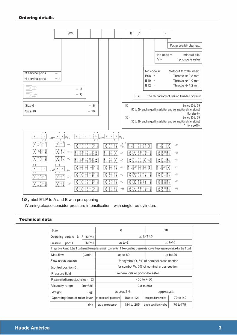
No code = mineral oils V = phospate ester
*WM B
3 service ports 3
4 service ports 4
U
R
Size 6 6
Size 10 10
B = The technology of Beijing Huade Hydraulic
95 ot 05 seireS = 05(50 to 59: unchanged installation and connection dimensions)
for size 693 ot 03 seireS = 03
(30 to 39: unchanged installation and connection dimensions)* for size10
1)Symbol E1:P to A and B with pre-opening Warning:please consider pressure intensification with single rod cylinders
Further details in clear text
No code = Without throttle insertB08 = Throttle 0.8 mmB10 = Throttle 1.0 mmB12 = Throttle 1.2 mm
Size 6 10
Operating ports A B P
Pressure port T
MPa
MPa
up to 31.5
up to 6 up to16
In symbols A and B,the T port must be used as a drain connection if the operating pressure is above the pressure permitted at the T port
Max.flow (L/min) 021ot pu06 ot pu
for symbol Q, 6% of nominal cross section
for symbol W, 3% of nominal cross section
Pressure fluid mineral oils or phospate ester
Pressure fluid temperature range C - 30 to + 80
Viscosity range mm2/s 2.8 to 500
Weight kg
Operating force at roller lever
(N)
approx.1.4 approx.3.3
at zero tank pressure 100 to 121 two positions valve 70 to140
at a pressure 184 to 205 three positions valve 70 to175
Flow cross section
control position 0
Ordering details
Technical data

Huade América 4
Symbols Direction of flow
P A P B A T B T
A 3 3 - -B 3 3 - -C 1 1 3 1D 5 5 3 3E 3 3 1 1F 1 3 1 1G 6 6 9 9H 2 4 2 2J 1 1 2 1L 3 3 4 9M 2 4 3 3P 3 1 1 1Q 1 1 2 1R 5 5 4 -T 10 10 9 9U 3 3 9 4V 1 2 1 1W 1 1 2 2Y 5 5 2 3
Symbols Direction of flow
P A P B A T B T
A 4 3 - -
B 3 4 - -C 3 3 4 4D 3 3 5 5Y 4 4 6 6E 2 2 4 4F 1 2 3 4
G T 4 4 7 7H 1 1 5 5J 2 2 3 3L 3 3 2 4M 1 1 4 4P 3 1 5 5Q 2 2 2 2R 3 4 3 - U 3 3 5 2V 2 2 3 3W 3 3 3 3
7 Symbol "R" with position A-B8 Symbols "G" and "T" with mid position P-T
Flow in L/min
aP
M ni ecnereffid erusserP
aP
M ni ecnereffid erusserP
Flow in L/min
WM R
6 U
WM R
10 U
7 Symbol "R" with position A-B8 Symbols "G" and "T" with mid position P-T
Characteristic curves (measured at = 41 mm 2 /s and t = 50 )

Huade América 5
WM=RU 6
Curve symbol
A1 B2 C D Y E E1 H M Q U W
F3 PG4
J5 LR6T7V8
The operation of the valve is dependent upon the effect of filtration .In order to achieve the given permissibleflow rates,full flow filtration 20μm is required.The flow forces operating within the valve influence the valveperformance .For 4 way valves,the flows given are valid for normal operation with 2 directions of flow (e.g.fromP to A and from B to T) If only one flow path is operative e.g.if port A or B is blocked and the valve is used as a3 way valve ,the permissible flows can be very much lower.
aPM ni erusserp gnitarep
O
Curve Symbol
A1 BH2
3 F G P R T4 J L Q U W5 C D E M V Y
Flow in L/min
WM RU 10
aPM ni erusserp gnitarep
O
Flow in L/minFlow in L/min
aPM ni erusserp gnitarep
O
aPM ni erusserp gnitarep
O
Flow in L/min
Performance limits (measured at v=41mm2 /s and t=50 )

Huade América 6
Rorler lever assembliednext to B end in 2-positionvalves of spools B.Y
Overrun may not be used as operational stroke
=tj=or=S
Subplates: see page 205
G341/01 G1/4" G341/02 M14X1.5G342/01 G3/8" G342/02 M18X1.5G502/01 G1/2" G502/02 M22X1.5
1 Spool position"a"2 Spool position"o"and"a" for 2- position
valve3 Spool position"b"4 Roller lever assembly may be stepped in 905 Nameplate6 Connection surface7 O-ring9.25X1.78 for ports A B P and T8 WMR the code"R"9 WMU the code"U"
depth
2-position valves3-position valves
)mm ni snoisnemiD( snoisnemid tinU

Huade América 7
tjo tjr
tj=orNM
Subplates: see page 206G66/01 G3/8" G66/02 M18X1.5G67/01 G1/2" G67/02 M22X1.5G534/01 G3/4" G534/02 M27X2
1 Two position valve B Y 2 Two position valve A C D 3 Three position valve 4 Nameplate 5 O-ring12X2 for ports A B P and T 6 Adjunctive port T can be connected with
ZDR10D... in special condition
Required surface finish ofmating piece
Rorler lever assembliednext to B end in 2-positionvalves of spools B.Y
)mm ni snoisnemiD( snoisnemid tinU