Embed Size (px)
Citation preview

Металлопрокат и трубыпо стандартам
DIN, EN, ASTM
Поставляем металлопрокат по стандарту ASTM B163
Стандарт предоставлен исключительно для ознакомления
Для заказа металлопрокатаили получения консультацииобращайтесь по следующим контактам:
Россия:
Беларусь:
Казахстан:
+7 (495) 134-41-64
+375 (29) 232-97-79
+7 (7172) 72-76-96
www.emk.bz [email protected]

Designation: B163 − 11´2
Standard Specification forSeamless Nickel and Nickel Alloy Condenser and Heat-Exchanger Tubes1
This standard is issued under the fixed designation B163; the number immediately following the designation indicates the year oforiginal adoption or, in the case of revision, the year of last revision. A number in parentheses indicates the year of last reapproval. Asuperscript epsilon (´) indicates an editorial change since the last revision or reapproval.
This standard has been approved for use by agencies of the U.S. Department of Defense.
ε1 NOTE—Title was corrected editorially in November 2012.ε2 NOTE—Yield strength heading for units in Table 3 was corrected editorially in March 2015.
1. Scope*
1.1 This specification2 covers seamless tubes of nickel andnickel alloys, as shown in Table 1, for use in condenser andheat-exchanger service.
1.2 This specification covers outside diameter and averagewall, or outside diameter and minimum wall tube.
1.2.1 The sizes covered by this specification are 3 in. (76.2mm) and under in outside diameter with minimum wallthicknesses of 0.148 in. (3.76 mm) and under, and with averagewall thicknesses of 0.165 in. (4.19 mm) and under.
1.3 Tube shall be furnished in the alloys and conditions asshown in Table 2. For small diameter and light wall tube(converter sizes), see Appendix X2.
1.4 The values stated in inch-pound units are to be regardedas standard. The values given in parentheses are mathematicalconversions to SI units that are provided for information onlyand are not considered standard.
1.5 The following safety hazards caveat pertains only to thetest method portion, Section 12, of this specification. Thisstandard does not purport to address all of the safety concerns,if any, associated with its use. It is the responsibility of the userof this standard to become familiar with all hazards includingthose identified in the appropriate Material Safety Data Sheet(MSDS) for this product/material as provided by themanufacturer, to establish appropriate safety and healthpractices, and determine the applicability of regulatory limi-tations prior to use.
2. Referenced Documents
2.1 ASTM Standards:3
B829 Specification for General Requirements for Nickel andNickel Alloys Seamless Pipe and Tube
B880 Specification for General Requirements for ChemicalCheck Analysis Limits for Nickel, Nickel Alloys andCobalt Alloys
E8 Test Methods for Tension Testing of Metallic MaterialsE18 Test Methods for Rockwell Hardness of Metallic Ma-
terialsE29 Practice for Using Significant Digits in Test Data to
Determine Conformance with SpecificationsE76 Test Methods for Chemical Analysis of Nickel-Copper
Alloys (Withdrawn 2003)4
E112 Test Methods for Determining Average Grain SizeE140 Hardness Conversion Tables for Metals Relationship
Among Brinell Hardness, Vickers Hardness, RockwellHardness, Superficial Hardness, Knoop Hardness, Sclero-scope Hardness, and Leeb Hardness
E1473 Test Methods for Chemical Analysis of Nickel,Cobalt, and High-Temperature Alloys
2.2 Federal Standards:5
Fed. Std. No. 102 Preservation, Packaging and PackingLevels
Fed. Std. No. 123 Marking for Shipment (Civil Agencies)Fed. Std. No. 182 Continuous Identification Marking of
Nickel and Nickel-Base Alloys
2.3 Military Standard:5
MIL-STD-129 Marking for Shipment and Storage
1 This specification is under the jurisdiction of ASTM Committee B02 onNonferrous Metals and Alloys and is the direct responsibility of SubcommitteeB02.07 on Refined Nickel and Cobalt and Their Alloys.
Current edition approved Oct. 1, 2011. Published October 2011. Originallyapproved in 1941. Last previous edition approved in 2008 as B163 – 08. DOI:10.1520/B0163-11E02.
2 For ASME Boiler and Pressure Vessel Code applications see related Specifi-cation SB-163 in Section II of that Code.
3 For referenced ASTM standards, visit the ASTM website, www.astm.org, orcontact ASTM Customer Service at [email protected]. For Annual Book of ASTMStandards volume information, refer to the standard’s Document Summary page onthe ASTM website.
4 The last approved version of this historical standard is referenced onwww.astm.org.
5 Available from Standardization Documents Order Desk, DODSSP, Bldg. 4,Section D, 700 Robbins Ave., Philadelphia, PA 19111-5098, http://www.dodssp.daps.mil.
*A Summary of Changes section appears at the end of this standard
Copyright © ASTM International, 100 Barr Harbor Drive, PO Box C700, West Conshohocken, PA 19428-2959. United States
1

TAB
LE
1C
hem
ical
Req
uir
emen
tsA
Com
posi
tion,
%
N02
200
N02
201
N04
400
N06
025
N06
045
N06
600
N06
601
N06
603
N06
686
N06
690
Nic
kel
99.0
min
B99
.0m
inB
63.0
min
Bre
mai
nder
B45
.0m
inB
72.0
min
B58
.0–6
3.0
rem
aind
erB
rem
aind
erB
58.0
min
B
Cop
per
0.25
0.25
28.0
–34.
00.
10.
30.
51.
00.
5...
0.5
Mol
ybde
num
......
......
......
......
15.0
–17.
0...
Iron
0.40
0.40
2.5
8.0–
11.0
21.0
–25.
06.
0–10
.0re
mai
nder
B8.
0–11
.05.
07.
0–11
.0M
anga
nese
0.35
0.35
2.0
0.15
1.0
1.0
1.0
0.15
0.75
0.5
Car
bon
0.15
0.02
0.3
0.15
–0.2
50.
05–0
.12
0.15
0.10
0.20
–0.4
00.
010
0.05
Sili
con
0.35
0.35
0.5
0.5
2.5–
3.0
0.5
0.5
0.5
0.08
0.5
Sul
fur
0.01
0.01
0.02
40.
010
0.01
00.
015
0.01
50.
010
0.02
0.01
5C
hrom
ium
......
...24
.0–2
6.0
26.0
–29.
014
.0–1
7.0
21.0
–25.
024
.0–2
6.0
19.0
–23.
027
.0–3
1.0
Alu
min
um...
......
1.8–
2.4
......
1.0–
1.7
2.4–
3.0
......
Tita
nium
......
...0.
1–0.
2...
......
0.01
–0.2
50.
02–0
.25
...P
hosp
horu
s...
......
0.02
00.
020
......
0.02
0.04
...C
eriu
m...
......
...0.
03–0
.09
......
......
...Z
ircon
ium
......
...0.
01–0
.10
......
...0.
01–0
.10
......
Yttr
ium
......
...0.
05–0
.12
......
...0.
01–0
.15
......
Bor
on...
......
......
......
......
...C
obal
t...
......
......
......
......
...C
olum
bium
(Nb)
......
......
......
......
......
Tung
sten
......
......
......
......
3.0–
4.4
...N
itrog
en...
......
......
......
......
...A
Max
imum
unle
ssra
nge
orm
inim
umis
give
n.W
here
ellip
ses
(...)
appe
arin
this
tabl
e,th
ere
isno
requ
irem
ent
and
anal
ysis
for
the
elem
ent
need
not
bede
term
ined
orre
port
ed.
BE
lem
ent
shal
lbe
dete
rmin
edar
ithm
etic
ally
bydi
ffere
nce.
B163 − 11´2
2

TAB
LE
1C
hem
ical
Req
uir
emen
tsA
(con
tinue
d)
N06
696
N06
845
N08
120
N08
800
N08
801
N08
810
N08
811
N08
825
Nic
kel
rem
aind
erB
44.0
–50.
035
.0–3
9.0
30.0
–35.
030
.0–3
4.0
30.0
–35.
030
.0–3
5.0
38.0
–46.
0C
oppe
r1.
5–3.
02.
0–4.
00.
500.
750.
500.
750.
751.
5–3.
0M
olyb
denu
m1.
0–3.
05.
0–7.
02.
50...
......
...2.
5–3.
5Ir
on2.
0–6.
0re
mai
nder
Bre
mai
nder
B39
.5m
inB
39.5
min
B39
.5m
inB
39.5
min
B22
.0m
inB
Man
gane
se1.
00.
51.
51.
51.
501.
51.
51.
0C
arbo
n0.
150.
050.
02–0
.10
0.10
0.10
0.05
–0.1
00.
06–0
.10
0.05
Sili
con
1.0–
2.5
0.5
1.0
1.0
1.00
1.0
1.0
0.5
Sul
fur
0.01
00.
010
0.03
0.01
50.
015
0.01
50.
015
0.03
Chr
omiu
m28
.0–3
2.0
20.0
–25.
023
.0–2
7.0
19.0
–23.
019
.0–2
2.0
19.0
–23.
019
.0–2
3.0
19.5
–23.
5A
lum
inum
......
0.40
0.15
–0.6
0...
0.15
–0.6
00.
15–0
.60C
0.2
Tita
nium
1.0
...0.
200.
15–0
.60
0.75
–1.5
0.15
–0.6
00.
15–0
.60C
0.6–
1.2
Pho
spho
rus
......
0.04
......
......
...C
eriu
m...
......
......
......
...Z
ircon
ium
......
......
......
......
Yttr
ium
......
......
......
......
Bor
on...
...0.
010
......
......
...C
obal
t...
...3.
0...
......
......
Col
umbi
um(N
b)...
...0.
4–0.
9...
......
......
Tung
sten
...2.
0–5.
02.
50...
......
......
Nitr
ogen
......
0.13
–0.3
0...
......
......
AM
axim
umun
less
rang
eor
min
imum
isgi
ven.
Whe
reel
lipse
s(.
..)ap
pear
inth
ista
ble,
ther
eis
nore
quire
men
tan
dan
alys
isfo
rth
eel
emen
tne
edno
tbe
dete
rmin
edor
repo
rted
.B
Ele
men
tsh
allb
ede
term
ined
arith
met
ical
lyby
diffe
renc
e.C
Allo
yU
NS
N08
811:
Al+
Ti,
0.85
−1.
20.
B163 − 11´2
3
3. Terminology
3.1 Definitions:3.1.1 average diameter, n—average of the maximum and
minimum outside diameters, as determined at any one crosssection of the tube.
3.1.2 tube, n—hollow product of round or any other crosssection having a continuous periphery.
4. Ordering Information
4.1 It is the responsibility of the purchaser to specify allrequirements that are necessary for the safe and satisfactoryperformance of material ordered under this specification.Examples of such requirements include, but are not limited to,the following:
4.1.1 Alloy (Table 1).4.1.2 Condition (Temper) Table 3 and Appendix X1 and
Appendix X2.4.1.2.1 If annealed ends for stress relieved tubing are
desired, state length of end to be annealed and whether or notone end or both ends are to be annealed.
4.1.3 Finish.4.1.4 Dimensions—Outside diameter, minimum or average
wall thickness (in inches, not gage number), and length.
4.1.5 Fabrication Operations:4.1.5.1 Cold Bending or Coiling.4.1.5.2 Packing.4.1.5.3 Rolling or Expanding into Tube Sheets.4.1.5.4 Welding or Brazing—Process to be employed.4.1.5.5 Hydrostatic Test or Nondestructive Electric Test—
Specify type of test (6.5).4.1.5.6 Pressure Requirements—If other than required by
6.5.4.1.5.7 Ends—Plain ends cut and deburred will be fur-
nished.4.1.6 Supplementary Requirements—State nature and de-
tails.4.1.7 Certification—State if certification is required (15).4.1.8 Samples for Product (Check) Analysis—Whether
samples for product (check) analysis shall be furnished.4.1.9 Purchaser Inspection—If purchaser wishes to witness
tests or inspection of material at place of manufacture, thepurchase order must so state indicating which tests or inspec-tions are to be witnessed (Section 13).
4.1.10 Small-Diameter and Light-Wall Tube (ConverterSizes)—See Appendix X2.
5. Chemical Composition
5.1 The material shall conform to the composition limitsspecified in Table 1.
5.2 If a product (check) analysis is performed by thepurchaser, the material shall conform to the product (check)analysis per Specification B880.
6. Mechanical Properties and Other Requirements
6.1 Mechanical Properties—The material shall conform tothe mechanical properties specified in Table 3.
6.2 Hardness—When annealed ends are specified for tubingin the stress-relieved condition (see Table 3), the hardness ofthe ends after annealing shall not exceed the values specified inTable 3.
6.3 Flare—A flare test shall be made on one end of 1 % ofthe number of finished tube lengths from each lot. For less than100 tubes in a lot, a flare test shall be made on one end of onetube length in the lot. In the case of stress relieved tubing withannealed ends, the test shall be made prior to, or subsequent to,annealing of the ends at the option of the manufacturer.
6.3.1 The flare test shall consist of flaring a test specimenwith an expanding tool having an included angle of 60° untilthe specified outside diameter has been increased by 30 %. Theflared specimen shall not exhibit cracking through the wall.
6.4 Grain Size—A transverse sample representing full-wallthickness of annealed alloys UNS N08120, UNS N08810 andUNS N08811 shall conform to an average grain size of ASTMNo. 5 or coarser.
6.5 Hydrostatic or Nondestructive Electric Test—Each tubeshall be subjected to either the hydrostatic test or the nonde-structive electric test. The type of test to be used shall be at theoption of the manufacturer, unless otherwise specified in thepurchase order.
6.5.1 Hydrostatic Test:
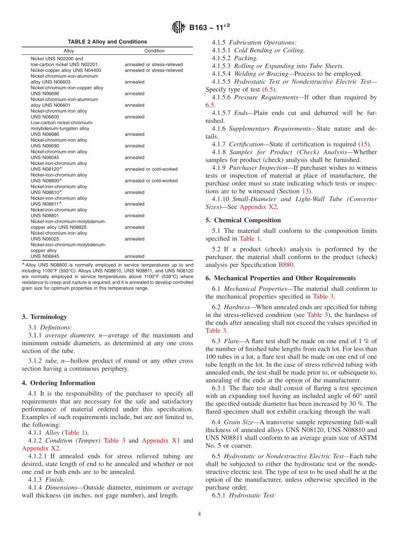
TABLE 2 Alloy and Conditions
Alloy Condition
Nickel UNS N02200 andlow-carbon nickel UNS N02201 annealed or stress-relievedNickel-copper alloy UNS N04400 annealed or stress-relievedNickel-chromium-iron-aluminumalloy UNS N06603 annealedNickel-chromium-iron-copper alloyUNS N06696 annealedNickel-chromium-iron-aluminumalloy UNS N06601 annealedNickel-chromium-iron alloyUNS N06600 annealedLow-carbon nickel-chromium-molybdenum-tungsten alloyUNS N06686 annealedNickel-chromium-iron alloyUNS N06690 annealedNickel-chromium-iron alloyUNS N06045 annealedNickel-iron-chromium alloyUNS N08120A annealed or cold-workedNickel-iron-chromium alloyUNS N08800A annealed or cold-workedNickel-iron-chromium alloyUNS N08810A annealedNickel-iron-chromium alloyUNS N08811A annealedNickel-iron-chromium alloyUNS N08801 annealedNickel-iron-chromium-molybdenum-copper alloy UNS N08825 annealedNickel-chromium-iron alloyUNS N06025 annealedNickel-iron-chromium-molybdenum-copper alloyUNS N06845 annealed
A Alloy UNS N08800 is normally employed in service temperatures up to andincluding 1100°F (593°C). Alloys UNS N08810, UNS N08811, and UNS N08120are normally employed in service temperatures above 1100°F (539°C) whereresistance to creep and rupture is required, and it is annealed to develop controlledgrain size for optimum properties in this temperature range.
B163 − 11´2
4

TABLE 3 Mechanical Properties of Tubes
Material and ConditionTensile Strength,min, ksi (MPa)
Yield Strength(0.2 % Offset),min, ksi (MPa)
Elongation in 2 in.or 50 mm (or 4 D)
min, %
Rockwell Hardness(or equivalent) forannealed endsA
Nickel UNS N02200:Annealed 55 (379) 15 (103) 40 ...Stress-relieved 65 (448) 40 (276) 15 B65 max
Low-carbon nickel UNS N02201:Annealed 50 (345) 12 (83) 40 ...Stress-relieved 60 (414) 30 (207) 15 B62 max
Nickel-copper alloy UNS N04400:Annealed 70 (483) 28 (193) 35 ...Stress-relieved 85 (586) 55 (379) 15 B75 max
Nickel-chromium-iron alloys:Annealed alloy UNS N06600 80 (552) 35 (241) 30 ...Annealed alloy UNS N06601 80 (552) 30 (207) 30 ...Annealed alloy UNS N06690 85 (586) 35 (241) 30 ...Annealed alloy UNS N06045 90 (620) 35 (240) 35 ...Annealed alloy UNS N06025 98 (680) 39 (270) 30 ...Annealed alloy UNS N06603 94 (650) 43 (300) 25 ...Annealed alloy UNS N06696 85 (586) 35 (240) 30 ...
Low-carbon nickel-chromium-molybdenum-tungsten alloy:Annealed UNS N06686 100 (690) 45 (310) 45 ...
Nickel-iron-chromium alloys:Annealed alloy UNS N08120 90 (620) 40 (276) 30 ...Annealed alloy UNS N08800 75 (517) 30 (207) 30 ...Annealed alloy UNS N08801 65 (448) 25 (172) 30 ...Cold-worked alloy UNS N08800 83 (572) 47 (324) 30 ...Annealed alloy UNS N08810 65 (448) 25 (172) 30 ...Annealed alloy UNS N08811 65 (448) 25 (172) 30 ...
Nickel-iron-chromium-molybdenum-copper-alloys:
Annealed UNS N08825 85 (586) 35 (241) 30 ...Annealed UNS N06845 100 (690) 40 (276) 30 ...A Rockwell or equivalent hardness values apply only to the annealed ends of stress-relieved tubing. Caution should be observed in using the Rockwell test on thin material,as the results may be affected by the thickness of specimen. For thickness under 0.050 in. (1.27 mm) the use of the Rockwell superficial or the Vickers hardness test issuggested. For hardness conversions for nickel and high-nickel alloys see Hardness Conversion Tables E140.
TABLE 4 Permissible Variations in Outside Diameter and Wall Thickness of Condenser and Heat Exchanger Tubes
NOTE 1—The tolerances in the table apply to individual measurements of outside diameter and include out-of-roundness (ovality), and apply to allmaterials and all conditions, except that for thin wall tubes having a nominal wall of 3 % or less of the outside diameter, the mean outside diameter shallcomply with the permissible variations of the above table and individual measurements (including ovality) shall conform to the plus and minus valuesof the table with the values increased by 1⁄2 % of the nominal outside diameter.
NOTE 2—Eccentricity—The variation in wall thickness in any one cross section of any one tube shall not exceed plus or minus 10 % of the actual(measured) average wall of that section. The actual average wall is defined as the average of the thickest and thinnest wall of that section.
NOTE 3—For tolerances of small diameter and light wall tube (converter sizes) see Appendix X2 (Table X2.2).
Material Nominal Outside Diameter, in. (mm)
Permissible VariationsA
Outside Diameter, in. (mm) Wall Thickness,%
+ −Average Wall Minimum Wall
+ − + −
UNS N02200, UNS N02201,and UNS N04400
1⁄2 to 5⁄8 (12.7 to 15.9), excl 0.005 (0.13) 0 12.5 12.5 25.0 0
5⁄8 to 11⁄2 (15.9 to 38.1), incl 0.005 (0.13) 0.005 (0.13) 10.0 10.0 20.0 0over 11⁄2 to 3 (38.1 to 76.2), incl 0.010 (0.25) 0.010 (0.25) 10.0 10.0 22.0 0
UNS N06600, UNS N06601, UNSN06690,
1⁄2 to 5⁄8 (12.7 to 15.9), excl 0.005 (0.13) 0.005 (0.13) 12.5 12.5 25.0 0
UNS N06045, UNS N06025, UNSN06603, UNS N06696, UNS N08800,UNS N08810, UNS N08811, UNSN08801,UNS N08825, UNS N06845, and UNSN08120UNS N06686 5⁄8 to 11⁄2 (15.9 to 38.1), incl 0.0075 (0.19) 0.0075 (0.19) 10.0 10.0 20.0 0
over 11⁄2 to 3 (38.1 to 76.2), incl 0.010 (0.25) 0.010 (0.25) 10.0 10.0 22.0 0A Wall variations as indicated above are applicable only to the wall as ordered, for instance, to minimum or to average wall, but not to both.
B163 − 11´2
5

6.5.1.1 Each tube with an outside diameter 1⁄8 in. (3.2 mm)and larger and tubes with wall thickness of 0.015 in. (0.38 mm)and over shall be tested by the manufacturer to an internalhydrostatic pressure of 1000 psi (6.9 MPa) provided that thefiber stress calculated in accordance with the following equa-tion does not exceed the allowable fiber stress, S, indicatedbelow. The tube shall show no evidence of leakage.
P 5 2St/D
where:P = hydrostatic test pressure, psi (MPa),S = allowable fiber stress for material in the condition
furnished, as follows:t = minimum wall thickness, in. (mm); equal to the speci-
fied average wall minus the permissible “minus” walltolerance, Table 4 and Table X2.2, or the specifiedminimum wall thickness, and
D = outside diameter of the tube, in. (mm).psi MPa
Annealed low-carbon nickel UNS N02201 8 000 55.2Stress-relieved low-carbon nickel UNS N02201 15 000 103.4Annealed nickel UNS N02200 10 000 68.9Stress-relieved nickel UNS N02200 16 200 111.7Annealed nickel-copper alloy UNS N04400 17 500 120.6Stress-relieved nickel-copper alloy UNS N04400 21 200 146.2Annealed nickel-chromium-iron alloy UNS N06600 20 000 137.9Annealed nickel-chromium-iron alloy UNS N06601 20 000 137.9Annealed nickel-chromium-iron alloy UNS N06690 21 200 146Annealed nickel-chromium-iron alloy UNS N06045 22 500 155Annealed nickel-chromium-iron alloy UNS N06025 24 500 169Solution annealed low-carbon nickel-chromium-molybdenum-tungsten alloy UNS N06686
25 000 172
Annealed nickel-chromium-iron-aluminum alloyUNS N06603 24 000 165Annealed nickel-chromium-iron-copper alloyUNS N06696 21 200 146Annealed nickel-iron-chromium alloy UNS N08120 22 500 155Annealed nickel-iron-chromium alloy UNS N08800 18 700 128.9Annealed nickel-iron-chromium alloy UNS N08810 16 600 114.4Annealed nickel-iron-chromium alloy UNS N08811 16 600 114.4Annealed nickel-iron-chromium alloy UNS N08801 16 600 114.4Annealed nickel-iron-chromium-molybdenum copperalloy UNS N08825 21 000 144.8Annealed nickel-iron-chromium-molydenum-copperalloy UNS N06845 21 200 146.2Cold-worked nickel-iron-chromium alloy UNS N08800 20 700 142.7
6.5.1.2 When so agreed upon between the manufacturer andthe purchaser, tube may be tested to 11⁄2 times the aboveallowable fiber stress.
6.5.1.3 When stress-relieved tubes with annealed ends are tobe tested hydrostatically, such pressure testing shall be doneprior to annealing of the ends of the tube.
6.5.2 Nondestructive Electric Test—Each tube shall be ex-amined with a nondestructive electric test as prescribed inSpecification B829.
7. Dimensions and Permissible Variations
7.1 Outside Diameter and Wall Thickness—The permissiblevariations in the outside diameter and wall thickness of tubeshall not exceed those prescribed in Table 4 and Table X2.2, asapplicable. (See also Table 5 and Table 6.)
7.2 Length—When tube is ordered cut-to-length, the lengthshall not be less than that specified, but a variation of plus 1⁄8in. (3.2 mm) will be permitted, except that for lengths over 30ft (9.1 m), a variation of plus 1⁄4 in. (6.4 mm) will be permitted.
7.3 Straightness—Material shall be reasonably straight andfree of bends or kinks.
8. Workmanship, Finish, and Appearance
8.1 The material shall be uniform in quality and temper,smooth, commercially straight, and free of injurious imperfec-tions.
9. Sampling
9.1 Lot—Definition:9.1.1 A lot for chemical analysis shall consist of one heat.9.1.2 A lot for mechanical properties, hardness, flaring, and
grain size testing shall consist of all material from the sameheat, nominal size (except length), and condition (temper).
9.1.2.1 Where material cannot be identified by heat, a lotshall consist of not more than 500 lb (230 kg) of material in thesame condition (temper) and size.
9.2 Test Material Selection:9.2.1 Chemical Analysis—Representative samples shall be
taken during pouring or subsequent processing.9.2.1.1 Product (check) analysis shall be wholly the respon-
sibility of the purchaser.9.2.2 Mechanical Properties, Hardness, and Grain Size—
Samples of the material to provide test specimens for mechani-cal properties, hardness, and grain size shall be taken from suchlocations in each lot as to be representative of that lot.
TABLE 5 Alloy,A Condition, Tube Size, and Bend Radii Limitations
Tube OD, in. (mm) Average Tube Wall, in. (mm)B
Minimum Bend Radius, in.(mm)
AnnealedCondition
Stress-RelievedCondition
Up to 1⁄2 (12.7), incl 0.046 to 0.057 (1.17 to 1.45), incl 13⁄16 (30.2) 11⁄4 (31.8)Up to 1⁄2 (12.7), incl Over 0.057 to 0.120 (1.45 to 3.05), incl 1 (25.4) 11⁄8 (28.6)Over 1⁄2 to 5⁄8 (12.7 to 15.9), incl 0.037 to 0.057 (0.94 to 1.45), incl 13⁄16 (30.2) 11⁄4 (31.8)Over 1⁄2 to 5⁄8 (12.7 to 15.9), incl Over 0.057 to 0.120 (1.45 to 3.05), incl 1 (25.4) 13⁄16 (30.2)Over 5⁄8 to 3⁄4 (15.9 to 19.0), incl 0.049 to 0.057 (1.24 to 1.45), incl 11⁄4 (31.8) 11⁄2 (38.1)Over 5⁄8 to 3⁄4 (15.9 to 19.0), incl Over 0.057 to 0.109 (1.45 to 2.77), incl 13⁄16 (30.2) 11⁄4 (31.8)Over 3⁄4 to 1 (19.0 to 25.4), incl 0.049 to 0.058 (1.24 to 1.47), incl 2 (50.8) 4 (101.6)Over 3⁄4 to 1 (19.0 to 25.4), incl Over 0.058 to 0.109 (1.47 to 2.77), incl 13⁄4 (44.5) 21⁄4 (57.2)
A Applies for all alloys except alloy UNS N08810, alloy UNS N08801, and UNS N08811.B To determine the bend radius applicable to minimum wall tubing, compute the corresponding average wall from the wall tolerances in Table 4, then use Table 5.
B163 − 11´2
6
10. Number of Tests
10.1 Chemical Analysis—One test per lot.
10.2 Mechanical Properties—One test per lot.
10.3 Hardness—A representative sample consisting of 3 %of each lot of tubes with annealed ends (see 9.1.2).
10.4 Grain Size—One test per lot.
10.5 Flare—A representative sample consisting of 1 % ofthe number of tube lengths in each lot, with a minimum of onetube per lot.
11. Specimen Preparation
11.1 Tension Test:11.1.1 Tension test specimens shall be taken from material
in the final condition (temper) and tested in the direction offabrication.
11.1.2 Whenever possible, all tubes shall be tested in fulltubular size. When testing in full tubular size is not possible,longitudinal strip specimens, or the largest possible roundspecimen, shall be used. In the event of disagreement when fulltubular testing is not possible, a longitudinal strip specimenwith reduced gage length as contained in Test Methods E8 shallbe used.
11.1.3 In the case of stress-relieved tubes furnished withannealed ends, the tension test shall be made on the stress-relieved tubes prior to annealing the ends.
11.2 Hardness Test:11.2.1 Stress-Relieved Tubing with Annealed Ends—The
hardness test may be made on the inside of the tube near theend or on a specimen cut from the end, at the option of themanufacturer. The test shall be made on the inside of thespecimen.
12. Test Methods
12.1 The chemical composition, mechanical, and otherproperties of the material as enumerated in this specificationshall be determined, in case of disagreement, in accordancewith the following methods:
Test ASTM DesignationChemical Analysis E76, E1473Tension E8Rounding Procedure E29Rockwell Hardness E18Grain Size E112Hardness Conversion E140
12.2 The measurement of average grain size may be carriedout by the planimetric method, the comparison method, or theintercept method described in Test Methods E112. In case ofdispute the “referee” method for determining average grainsize shall be the planimetric method.
12.3 For purposes of determining compliance with thespecified limits for requirements of the properties listed in thefollowing table, an observed value or a calculated value shallbe rounded as indicated below, in accordance with the round-ing method of Practice E29:
TestRounded Unit for Observed
or Calculated ValueChemical composition, hardness,and tolerances (when expressedin decimals)
nearest unit in the last right-hand place offigures of the specified limit
Tensile strength, yield strength nearest 1000 psi (6.9 MPa)Elongation nearest 1 %Grain size:
0.0024 in. (0.060 mm) or larger nearest multiple of 0.0002 in. (0.005 mm)less than 0.0024 in. (0.060 mm) nearest multiple of 0.0001 in. (0.002 mm)
13. Inspection
13.1 Inspection of the material shall be made as agreed uponbetween the manufacturer and the purchaser as part of thepurchase contract.
14. Rejection and Rehearing
14.1 Material not conforming to this specification or toauthorized modifications will be subject to rejection.
14.2 Samples tested in accordance with this specificationthat represent rejected material shall be preserved for not lessthan three weeks from the date of the test report. In case ofdissatisfaction with the results of the tests, the manufacturermay make claim for a rehearing within that time.
15. Certification
15.1 When specified in the purchase order or contract, amanufacturer’s certification shall be furnished to the purchaserstating that material has been manufactured, tested, and in-spected in accordance with this specification, and that the testresults on representative samples meet specification require-ments. When specified in the purchase order or contract, areport of the test results shall be furnished.
16. Product Marking
16.1 Each bundle or shipping container shall be markedwith the name of the material; condition (temper); this speci-fication number; the size; gross, tare, and net weight; consignorand consignee address; contract or order number; or such otherinformation as may be defined in the contract or order.
17. Keywords
17.1 seamless tube; UNS N02200; UNS N02201; UNSN04400; UNS N06025; UNS N06045; UNS N06600; UNSN06601; UNS N06603; UNS N06686; UNS N06690; UNSN06696; UNS N06845; UNS N08120; UNS N08800; UNSN08801; UNS N08810; UNS N08811; UNS N08825
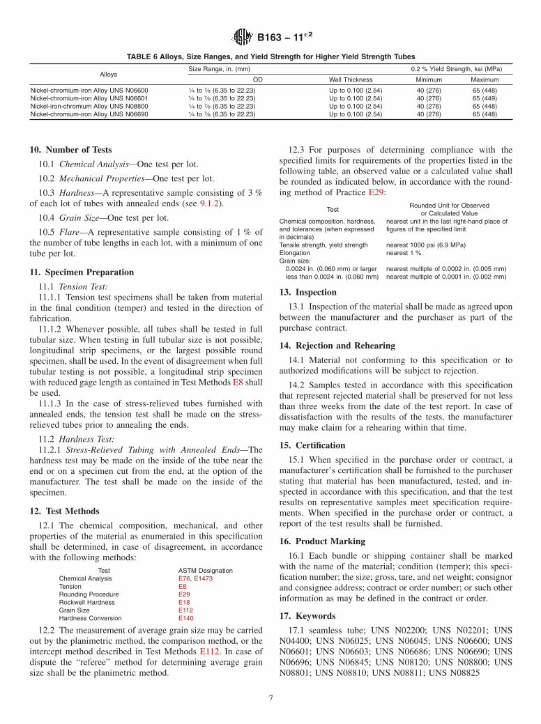
TABLE 6 Alloys, Size Ranges, and Yield Strength for Higher Yield Strength Tubes
AlloysSize Range, in. (mm) 0.2 % Yield Strength, ksi (MPa)
OD Wall Thickness Minimum Maximum
Nickel-chromium-iron Alloy UNS N06600 1⁄4 to 7⁄8 (6.35 to 22.23) Up to 0.100 (2.54) 40 (276) 65 (448)Nickel-chromium-iron Alloy UNS N06601 1⁄4 to 7⁄8 (6.35 to 22.23) Up to 0.100 (2.54) 40 (276) 65 (449)Nickel-iron-chromium Alloy UNS N08800 1⁄4 to 7⁄8 (6.35 to 22.23) Up to 0.100 (2.54) 40 (276) 65 (448)Nickel-chromium-iron Alloy UNS N06690 1⁄4 to 7⁄8 (6.35 to 22.23) Up to 0.100 (2.54) 40 (276) 65 (448)
B163 − 11´2
7

SUPPLEMENTARY REQUIREMENTS
S1. U-BENT TUBES
The following supplementary requirements shall apply when U-bent tubes are specified by thepurchaser in the inquiry, contract, or order.
S1.1 Limitation of Supplementary Requirements forU-Bent Tubes
S1.1.1 The requirements for U-bent tubes included in thissupplement are limited to the alloys, conditions (tempers), tubeoutside diameter (OD), and wall thickness ranges and bendradii listed in Table 5.
S1.2 Permissible Variations in Dimensions (Fig. S1.1)
S1.2.1 Leg Spacing—The leg spacing, measured betweenthe points of tangency of the bend to the legs shall not varyfrom the value (2R − specified tube OD) by more than theamounts shown below where R is the specified centerline bendradius:
Centerline Bend Radius (R), in. (mm) Tolerance, in. (mm)Up to 18 (457), incl 1⁄16 (1.6)Over 18 to 30 (457 to 762), incl 3⁄32 (2.4)Over 30 to 36 (762 to 914), incl 1⁄8 (3.2)
S1.2.2 Diameter of Tube in U-Bent Section—Neither themajor, nor the minor outside diameter of the tube at any onecross section included within the points of tangency of the bendshall deviate from the nominal diameter prior to bending bymore than 10 %.
S1.2.3 Wall Thickness of Tube in U-Bent Section—The wallthickness of the tube at the apex of the U-bent section shall benot less than the value determined by the following equation:
TF 5 T~2R!/~2R1D!
where:
TF = thickness after bending, in. (mm),T = minimum permissible thickness of tube wall prior to
bending, in. (mm),R = centerline bend radius, in. (mm), andD = nominal outside diameter of the tube, in. (mm).
When specified by the purchaser, proof of conformance tothis requirement shall be obtained by bending a tube specimen,representative of the material offered, to the scheduled radiusof bend, cutting the tube at the apex of the bend, measuring thetube wall at the cross section of this apex section, andcomparing the measured value with the calculated value of TF.
S1.2.4 Length of U-Bend Tube Legs—The length of the tubelegs as measured from the point of tangency of the bend andthe tube leg to the end of the tube leg shall not be less than thatspecified, but may exceed the specified values by the followingamounts:
Specified Length (L), ft (m) Tolerance (all Plus), in. (mm)Up to 20 (6.1), incl 1⁄8 (3.2)Over 20 to 30 (6.1 to 9.1), incl 5⁄32 (4.0)Over 30 to 60 (9.1 to 18.3), incl 1⁄4 (6.4)Over 60 (18.3) 3⁄8 (10.0)
S1.2.4.1 The difference in the length of the tube legs shallnot be greater than 1⁄8 in. (3.2 mm).
S1.2.5 Squareness of Ends—The end of any tube may departfrom square by not more than the following amounts:
Tube OD, in. (mm) Tolerance, in. (mm)Up to 5⁄8 (15.9), incl 0.010 (0.25)Over 5⁄8 (15.9) 0.016 (0.41)
FIG. S1.1 Bent Portion of U-Tube
B163 − 11´2
8

S1.3 Hydrostatic Test
S1.3.1 When specified by the purchaser, the hydrostatic testshall be performed after bending. The minimum holding timeat pressure shall be 5 s.
S1.3.1.1 When hydrostatic testing is performed afterbending, such testing will not be required on straight lengthtubes prior to bending.
S1.3.1.2 The required fiber stress for computing hydrostatictest pressure shall be 26 600 psi (183.3 MPa).
S2. HIGH YIELD STRENGTH TUBES
The following supplementary requirements shall apply when high yield strength tubes are specified by the purchaser in theinquiry, contract, or purchase order.
S2.1 Limitations of Supplementary Requirements for HighYield Strength Tubes
S2.1.1 The requirements for higher yield strength tubesincluded in this supplement are limited to the alloys, tubeoutside diameter (OD), and wall thickness ranges listed inTable 6.
S2.2 Higher Yield Strength
S2.2.1 The 0.2 % yield strength shall be as listed in Table 6.All other mechanical properties shall be as listed in Table 3.
S2.3 Degree of Cold Work
S2.3.1 No additional cold working over and above thatnormally required for these alloys shall be used in order tomeet the higher yield strength.
S2.4 Annealing
S2.4.1 Tubing is to be furnished in the annealed condition. Inorder to meet the higher yield strength requirement, it may benecessary to control the final annealing parameters so as topreclude large grain sizes.
S2.5 Marking Requirements
S2.5.1 In addition to the marking requirements of SB-163,the marking shall include the letters HYS signifying higheryield strength.
S3. COILED OR UNSTRAIGHTENED TUBING
The following supplementary requirements shall apply when coiled or unstraightened tubing is specified by the purchaser inthe inquiry, contract, or purchase order.
S3.1 Unstraightened Tubing
S3.1.1 When the purchaser specifies coiled or unstraightenedtubing after final heat treatment, the tensile specimens may bemachine straightened prior to testing.
S3.1.2 On the certification and wherever the grade designa-tion for unstraightened tubing appears, it shall be identifiedwith the suffix letter “U” (for example, UNS N06600–U).
S4. U.S. GOVERNMENT
The following supplementary requirements shall apply only when specified by the purchaser in the inquiry, contract, or orderfor agencies of the U.S. Government.
S4.1 Referenced Documents
S4.1.1 The following documents of the issue in effect on dateof material purchased form a part of this specification to theextent referenced herein: Fed. Std. No. 102, Fed. Std. No. 123,Fed. Std. No. 182, and MIL-STD-129.
S4.2 Quality Assurance
S4.2.1 Responsibility for Inspection:S4.2.1.1 Unless otherwise specified in the contract or pur-
chase order, the manufacturer is responsible for the perfor-mance of all inspection and test requirements specified. Except
B163 − 11´2
9
as otherwise specified in the contract or purchase order, themanufacturer may use his own or any other suitable facilitiesfor the performance of the inspection and test requirementsunless disapproved by the purchaser at the time the order isplaced. The purchaser shall have the right to perform any of theinspections or tests set forth when such inspections and testsare deemed necessary to ensure that the material conforms toprescribed requirements.
S4.3 Identification Marking
S4.3.1 The material shall be properly marked for identifica-tion in accordance with Fed. Std. No. 182 except that theASTM specification number and the alloy number shall beused.
S4.4 Preparation for Delivery
S4.4.1 Preservation, Packaging, Packing:
S.4.4.1.1 Military Agencies—The material shall be separatedby size, composition, grade or class and shall be preserved andpackaged, level A or C, packed level A, B, or C as specified inthe contract or purchase order.
S4.4.1.2 Civil Agencies—The requirements of Fed. Std. No.102 shall be referenced for definitions of the various levels ofpackaging protection.
S4.4.2 Marking:
S4.4.2.1 Military Agencies—In addition to any specialmarking required by the contract or purchase order, markingfor shipment shall be in accordance with MIL-STD-129.
S4.4.2.2 Civil Agencies—In addition to any special markingrequired by the contract or purchase order, marking forshipment shall be in accordance with Fed. Std. No. 123.
APPENDIXES
(Nonmandatory Information)
X1. CONDITION AND FINISHES NORMALLY SUPPLIED
X1.1 Scope
X1.1.1 This appendix lists the conditions and finishes inwhich tube (other than converter sizes) are normally supplied.These are subject to change and the manufacturer should beconsulted for the latest information available.
X1.2 Nickel UNS N02200
X1.2.1 Annealed—Soft, with a dull matte finish.
X1.2.2 Stress Relieved—Thermally treated below the an-nealing temperature to relieve the major portion of the internalstresses, with a thin, light to medium-dark surface.
X1.2.3 Stress Relieved with Annealed Ends—Same asX1.2.2 except with annealed ends.
X1.3 Low-Carbon Nickel UNS N02201
X1.3.1 Annealed—Similar to X1.2.1
X1.3.2 Stress Relieved—Similar to X1.2.2
X1.3.3 Stress-Relieved With Annealed Ends—Same asX1.3.2 except with annealed ends.
X1.4 Nickel-Copper Alloy UNS N04400
X1.4.1 Annealed—Soft with a dull matte finish.
X1.4.2 Stress Relieved—Thermally treated below the an-nealing temperature to relieve the major portion of the internalstresses resulting from cold drawing, with a thin, light tomedium-dark surface.
X1.4.3 Stress-Relieved With Annealed Ends—Same asX1.4.2 except with annealed ends.
X1.5 Nickel-Chromium-Iron Alloy UNS N06600, Nickel-Chromium-Iron Alloy UNS N06601, Nickel-Chromium-Iron Alloy UNS N06690, Nickel-Chromium-Iron Alloy UNS N06045, Nickel-Chromium-Iron Alloy UNS N06025, Nickel-Iron-Chromium Alloys (UNS N08120, UNS N08800, UNSN08810, UNS N08811, and UNS N08801), andNickel-Iron-Chromium-Molybdenum-Copper AlloysUNS N08825 and UNS N06845
X1.5.1 Annealed and Ground Outside Diameter—The in-side diameter may have a bright finish when material isannealed in protective atmosphere; otherwise, the inside diam-eter is supplied descaled as necessary.
X1.5.2 Annealed and Pickled (Not Ground)—Outside andinside diameter will have dull, matte (pickled) surfaces.
B163 − 11´2
10
X2. CONVERTER SIZES
X2.1 Small diameter and light wall tube in outside diam-eters 11⁄4 in. (31.8 mm) and under all wall thicknesses may befurnished in the following conditions or tempers when sospecified. The material is furnished in a limited range of sizesand the manufacturer should be consulted as to the various
outside diameters and wall thicknesses that may be furnished.Material shall be clean and scale-free. Such material shallconform to the applicable requirements indicated in Table X2.1and Table X2.2.
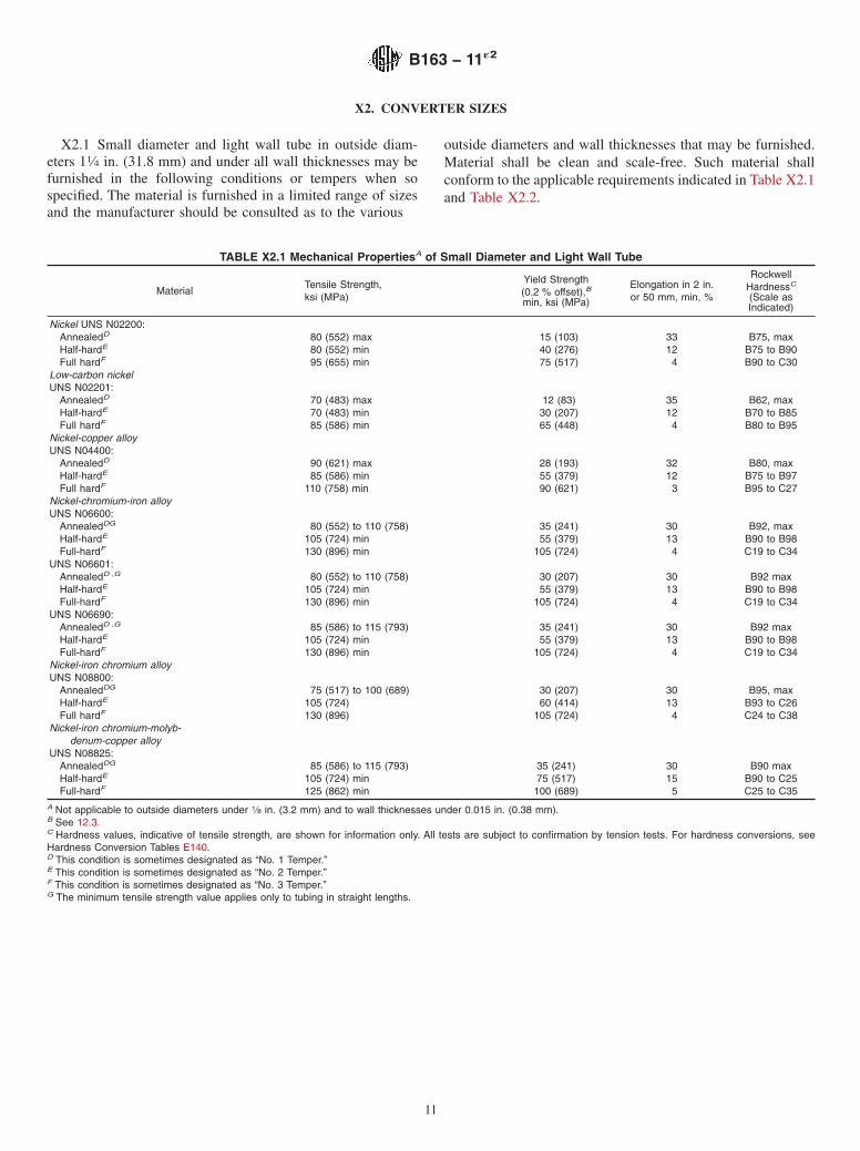
TABLE X2.1 Mechanical PropertiesA of Small Diameter and Light Wall Tube
MaterialTensile Strength,ksi (MPa)
Yield Strength(0.2 % offset),Bmin, ksi (MPa)
Elongation in 2 in.or 50 mm, min, %
RockwellHardnessC
(Scale asIndicated)
Nickel UNS N02200:AnnealedD 80 (552) max 15 (103) 33 B75, maxHalf-hardE 80 (552) min 40 (276) 12 B75 to B90Full hardF 95 (655) min 75 (517) 4 B90 to C30
Low-carbon nickelUNS N02201:
AnnealedD 70 (483) max 12 (83) 35 B62, maxHalf-hardE 70 (483) min 30 (207) 12 B70 to B85Full hardF 85 (586) min 65 (448) 4 B80 to B95
Nickel-copper alloyUNS N04400:
AnnealedD 90 (621) max 28 (193) 32 B80, maxHalf-hardE 85 (586) min 55 (379) 12 B75 to B97Full hardF 110 (758) min 90 (621) 3 B95 to C27
Nickel-chromium-iron alloyUNS N06600:
AnnealedDG 80 (552) to 110 (758) 35 (241) 30 B92, maxHalf-hardE 105 (724) min 55 (379) 13 B90 to B98Full-hardF 130 (896) min 105 (724) 4 C19 to C34
UNS N06601:AnnealedD ,G 80 (552) to 110 (758) 30 (207) 30 B92 maxHalf-hardE 105 (724) min 55 (379) 13 B90 to B98Full-hardF 130 (896) min 105 (724) 4 C19 to C34
UNS N06690:AnnealedD ,G 85 (586) to 115 (793) 35 (241) 30 B92 maxHalf-hardE 105 (724) min 55 (379) 13 B90 to B98Full-hardF 130 (896) min 105 (724) 4 C19 to C34
Nickel-iron chromium alloyUNS N08800:
AnnealedDG 75 (517) to 100 (689) 30 (207) 30 B95, maxHalf-hardE 105 (724) 60 (414) 13 B93 to C26Full hardF 130 (896) 105 (724) 4 C24 to C38
Nickel-iron chromium-molyb-denum-copper alloy
UNS N08825:AnnealedDG 85 (586) to 115 (793) 35 (241) 30 B90 maxHalf-hardE 105 (724) min 75 (517) 15 B90 to C25Full-hardF 125 (862) min 100 (689) 5 C25 to C35
A Not applicable to outside diameters under 1⁄8 in. (3.2 mm) and to wall thicknesses under 0.015 in. (0.38 mm).B See 12.3.C Hardness values, indicative of tensile strength, are shown for information only. All tests are subject to confirmation by tension tests. For hardness conversions, seeHardness Conversion Tables E140.D This condition is sometimes designated as “No. 1 Temper.”E This condition is sometimes designated as “No. 2 Temper.”F This condition is sometimes designated as “No. 3 Temper.”G The minimum tensile strength value applies only to tubing in straight lengths.
B163 − 11´2
11

SUMMARY OF CHANGES
Committee B02 has identified the location of selected changes to this standard since the last issue (B163 - 08)that may impact the use of this standard. (Approved October 1, 2011.)
(1) Corrected the Fe content of UNS N06601 and the Nicontent of UNS N06045, both in Table 1.(2) Revised Note A of Table 1.
(3) Added new nickel-iron-chromium-molybdenum-copperally UNS N06845 in: Subsection 6.5.1.1, Section 17, Table 1,Table 2, Table 3, Table 4, and Appendix X1.
TABLE X2.2 Permissible Variations for Small Diameter and Light Wall Tube (Converter Sizes)
NOTE 1—Ovality, Normal Wall Tube:As-Drawn (No. 2 and 3) Tempers—Ovality will be held within the outside diameter tolerances shown in the table.Annealed (No. 1) Temper—Ovality will be held within 2 % of the theoretical average outside diameter.
NOTE 2—Ovality Light Wall Tube:As-Drawn (No. 2 and 3) Tempers—Ovality will be held within 2 % of the theoretical average outside diameter.Annealed (No. 1) Temper—Ovality will be held within 3 % of the theoretical average outside diameter.
NOTE 3—Wall Tolerances, Light Wall Tube—The plus and minus wall tolerance shown in the table shall apply down to and including 0.005 in. (0.13mm) in wall thickness. For wall thicknesses less than 0.005 in. the tolerance shall be plus and minus 0.0005 in.
NOTE 4—Random Lengths:(a) Where nominal random lengths on tubing 1⁄8 in. and larger in outside diameter are specified, a length tolerance of plus and minus 31⁄2 ft (1.1 m) appliesto the nominal length. This is a total spread of 7 ft. (2.1 m).(b) Random lengths in sizes 1⁄8 in. (3.2 mm) and larger in outside diameter shall be subject to a length range from 5 to 24 ft (1.5 to 7.3 m). Long randomlengths are subject to a range from 15 to 22 ft (4.6 to 6.7 m).(c) Random lengths in sizes up to, but not including, 1⁄8 in. in outside diameter, and fragile light wall tubes over this outside diameter are subject to thelength range from 1 to 15 ft (0.3 to 4.6 m).
NOTE 5—Cut Lengths—Tolerances on cut lengths shall be as follows:
NOTE 6—Straightness—Round tubing is subject to a straightness tolerance of one part in 600 (equivalent to a depth of arc of 0.030 in. (0.76 mm) inany 3 ft (0.9 m) of length).
NOTE 7—Eccentricity—Eccentricity (as defined in Table 4, Note 2) shall be limited to plus or minus 10 % of the specified wall or calculated averagewall.
NOTE 8—When specified, the tolerance spread may be applied as desired. However, when not specified the tolerances shown below will apply. It shouldbe noted that inside diameter tolerances are based upon the outside diameter range.
Length, ft Tube Size, in.Permissible Variations, in.
Over UnderU.S. Customary Units
Under 1 Up to 1.250, incl 1⁄32 01 to 4, incl Up to 1.250, incl 1⁄16 0Over 4 to 10, incl Up to 1.250, incl 3⁄32 0Over 10 Up to 1.250, incl 3⁄16 0
Metric Units
Length, m Tube Size, mmPermissible Variations, mm
Over UnderUnder 0.3 Up to 31.75, incl 0.794 00.3 to 1.2, incl Up to 31.75, incl 1.59 01.2 to 3.0, incl Up to 31.75, incl 2.38 0Over 3.0 Up to 31.75, incl 4.76 0
Specified Outside Diameter, in.Outside Diameter, in. Inside Diameter, in. Wall Thickness,%
+ − + − + −
U.S. Customary UnitsUnder 3⁄32 0.002 0 0 0.002 10 10to 3⁄16 (0.1875), excl 0.003 0 0 0.003 10 103⁄16 to 1⁄2 (0.500), excl 0.004 0 0 0.004 10 101⁄2 to 11⁄4 (1.250), incl 0.005 0 0 0.005 10 10
MillimetresUnder 2.38 0.051 0 0 0.051 10 102.38 to 4.76, excl 0.076 0 0 0.076 10 104.76 to 12.70, excl 0.102 0 0 0.102 10 1012.70 to 31.8, incl 0.127 0 0 0.127 10 10
B163 − 11´2
12
ASTM International takes no position respecting the validity of any patent rights asserted in connection with any item mentionedin this standard. Users of this standard are expressly advised that determination of the validity of any such patent rights, and the riskof infringement of such rights, are entirely their own responsibility.
This standard is subject to revision at any time by the responsible technical committee and must be reviewed every five years andif not revised, either reapproved or withdrawn. Your comments are invited either for revision of this standard or for additional standardsand should be addressed to ASTM International Headquarters. Your comments will receive careful consideration at a meeting of theresponsible technical committee, which you may attend. If you feel that your comments have not received a fair hearing you shouldmake your views known to the ASTM Committee on Standards, at the address shown below.
This standard is copyrighted by ASTM International, 100 Barr Harbor Drive, PO Box C700, West Conshohocken, PA 19428-2959,United States. Individual reprints (single or multiple copies) of this standard may be obtained by contacting ASTM at the aboveaddress or at 610-832-9585 (phone), 610-832-9555 (fax), or [email protected] (e-mail); or through the ASTM website(www.astm.org). Permission rights to photocopy the standard may also be secured from the Copyright Clearance Center, 222Rosewood Drive, Danvers, MA 01923, Tel: (978) 646-2600; http://www.copyright.com/
B163 − 11´2
13