Embed Size (px)
Citation preview

6-1
C h a p t e r 6
Dimensioning the Circular Problem
This chapter will cover:
1. Dimensioning Styles 2. Trimming Centerlines with the IntelliTrim Tool 3. The Radial Dimension Tool 4. Linear Dimension Tools 5. The Arc Distance Tool 6. The Dimension Angle Size Tool 7. The Place Text Tool
6-2
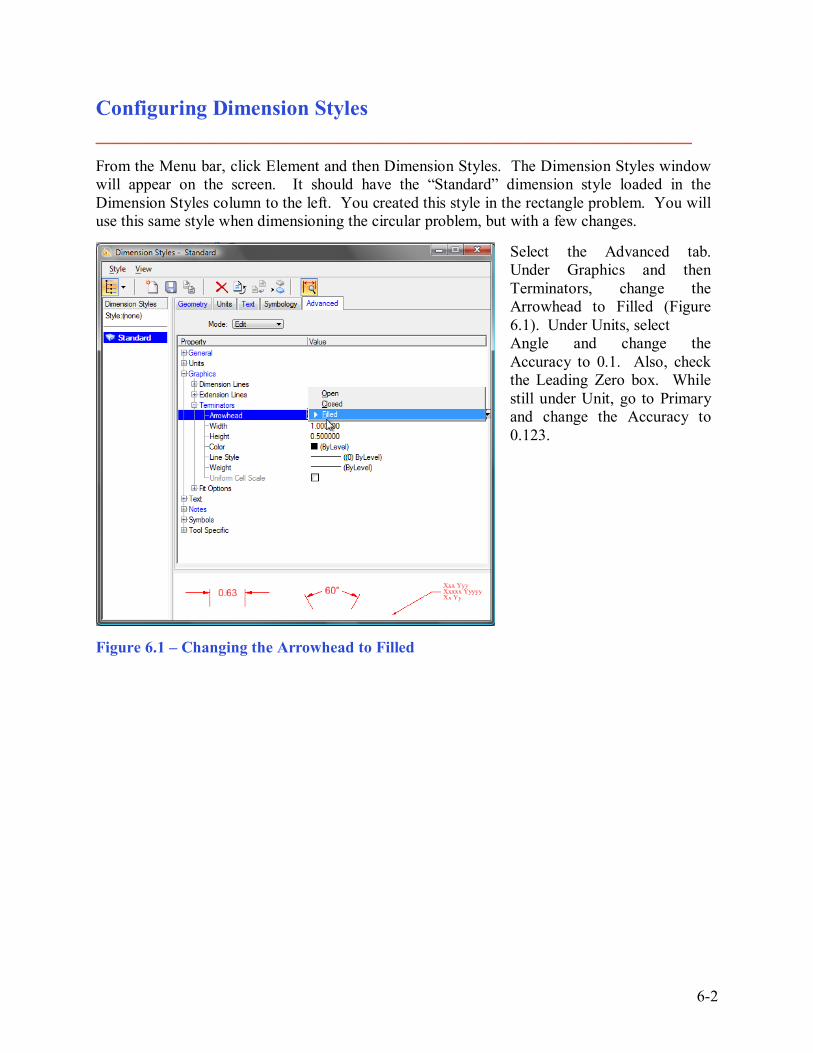
Configuring Dimension Styles ________________________________________________________ From the Menu bar, click Element and then Dimension Styles. The Dimension Styles window will appear on the screen. It should have the �Standard� dimension style loaded in the Dimension Styles column to the left. You created this style in the rectangle problem. You will use this same style when dimensioning the circular problem, but with a few changes.
Select the Advanced tab. Under Graphics and then Terminators, change the Arrowhead to Filled (Figure 6.1). Under Units, select Angle and change the Accuracy to 0.1. Also, check the Leading Zero box. While still under Unit, go to Primary and change the Accuracy to 0.123.
Figure 6.1 � Changing the Arrowhead to Filled

6-3
Figure 6.2 � Changing the Location to Inline
Under Text and then Format, change the Location to Inline (Figure 6.2). Under Style, select Standard to be the Active Text Style in the Text Style drop box on the Dimension Styles window. Save the Standard dimension style and then exit the Dimension Styles window. Next, select Text Styles from the Element menu on the menu bar and the Text Styles window will appear. If the Standard text style you created during the rectangle problem is not present, create a new text style named Standard. Change the Height to 0.15 and the font to 32 INTL_ENGINEERING (Figure 6.3). Save the text style and close the Text Styles window.
Figure 6.3 � The Standard Text Style
6-4
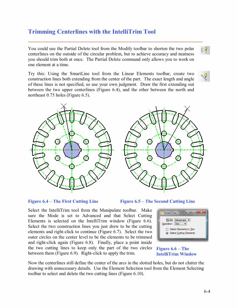
Trimming Centerlines with the IntelliTrim Tool ________________________________________________________ You could use the Partial Delete tool from the Modify toolbar to shorten the two polar centerlines on the outside of the circular problem, but to achieve accuracy and neatness you should trim both at once. The Partial Delete command only allows you to work on one element at a time. Try this: Using the SmartLine tool from the Linear Elements toolbar, create two construction lines both extending from the center of the part. The exact length and angle of these lines is not specified, so use your own judgment. Draw the first extending out between the two upper centerlines (Figure 6.4), and the other between the north and northeast 0.75 holes (Figure 6.5).
Figure 6.4 � The First Cutting Line Figure 6.5 � The Second Cutting Line
Select the IntelliTrim tool from the Manipulate toolbar. Make sure the Mode is set to Advanced and that Select Cutting Elements is selected on the IntelliTrim window (Figure 6.6). Select the two construction lines you just drew to be the cutting elements and right-click to continue (Figure 6.7). Select the two outer circles on the center level to be the elements to be trimmed and right-click again (Figure 6.8). Finally, place a point inside the two cutting lines to keep only the part of the two circles between them (Figure 6.9). Right-click to apply the trim.
Figure 6.6 � The IntelliTrim Window
Now the centerlines still define the center of the arcs in the slotted holes, but do not clutter the drawing with unnecessary details. Use the Element Selection tool from the Element Selecting toolbar to select and delete the two cutting lines (Figure 6.10).

6-5
Figure 6.7 � The Cutting Lines Figure 6.8 � The Lines to Trim
Figure 6.9 � The Portions to Keep Figure 6.10 � The Cutting Lines Removed
Using the Radial Dimension Tool ________________________________________________________ Before you can begin dimensioning the circular problem, you must first change to the Dimension level by selecting it from the Active Level combo box. Then you can select the Dimension Radial tool from the Radial Dimension toolbar.

6-6
The Dimension Radial tool allows you to place an assortment of dimensions without switching tools. In the Dimension Radial window, make sure that Standard is selected in the Active level drop box. Change the Mode to Diameter Extended and the Alignment to View (Figure 6.11). Now you can place four diameter dimensions: the 12, 5, 2.5, and 0.75 unit circles. Try to place the dimensions in similar positions to what you see in the examples (Figure 6.12). This will ensure you will not encounter any layout problems.
Figure 6.11 � The Dimension Radial Window
To place a diameter dimension, click the circular element you would like to dimension, and then select a point to place the text. These should be relatively simple.
Figure 6.12 � The Diameter Dimensions Change the Mode from Diameter Extended to Radius Extended on the Dimension Radial window. Now you can dimension two more objects: the inner center-arc you trimmed earlier in this chapter (Figure 6.13), and the arc of the slotted hole (Figure 6.14).

6-7
Figure 6.13 � The Radius of the Inner Center Arc
Figure 6.14 � The Radius of the Slotted Hole
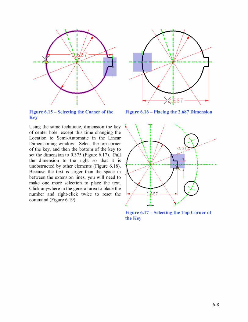
Using Linear Dimension Tools ________________________________________________________ Select the Dimension Linear tool from the Dimensioning toolbar and the Linear Dimensioning window will appear. Once again, make sure the Standard dimension style is selected, and change the Alignment to View. Place the first linear dimension on the center hole. Select the bottom corner of the key slot as the first point of the dimension, and the AccuDraw compass will appear. Click the west quadrant of the center hole to finish set the length of the dimension (Figure 6.15). The length should be 2.687; if it is not, hit CTRL+Z to Undo the dimension and try again, zooming in if needed to select the exact points. Pull the dimension down below the keyhole and left-click to place it (Figure 6.16). If you are having trouble with accuracy, try selecting the Intersection Snap from Snap Mode toolbar. Right-click twice to reset the command.
6-8
Figure 6.15 � Selecting the Corner of the Key
Figure 6.16 � Placing the 2.687 Dimension
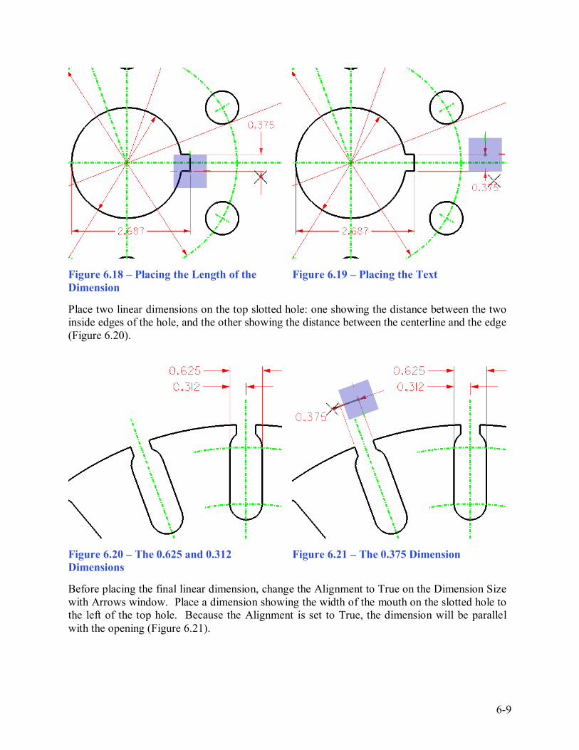
Using the same technique, dimension the key of center hole, except this time changing the Location to Semi-Automatic in the Linear Dimensioning window. Select the top corner of the key, and then the bottom of the key to set the dimension to 0.375 (Figure 6.17). Pull the dimension to the right so that it is unobstructed by other elements (Figure 6.18). Because the text is larger than the space in between the extension lines, you will need to make one more selection to place the text. Click anywhere in the general area to place the number and right-click twice to reset the command (Figure 6.19).
Figure 6.17 � Selecting the Top Corner of the Key
6-9
Figure 6.18 � Placing the Length of the Dimension
Figure 6.19 � Placing the Text
Place two linear dimensions on the top slotted hole: one showing the distance between the two inside edges of the hole, and the other showing the distance between the centerline and the edge (Figure 6.20).
Figure 6.20 � The 0.625 and 0.312 Dimensions
Figure 6.21 � The 0.375 Dimension
Before placing the final linear dimension, change the Alignment to True on the Dimension Size with Arrows window. Place a dimension showing the width of the mouth on the slotted hole to the left of the top hole. Because the Alignment is set to True, the dimension will be parallel with the opening (Figure 6.21).
6-10
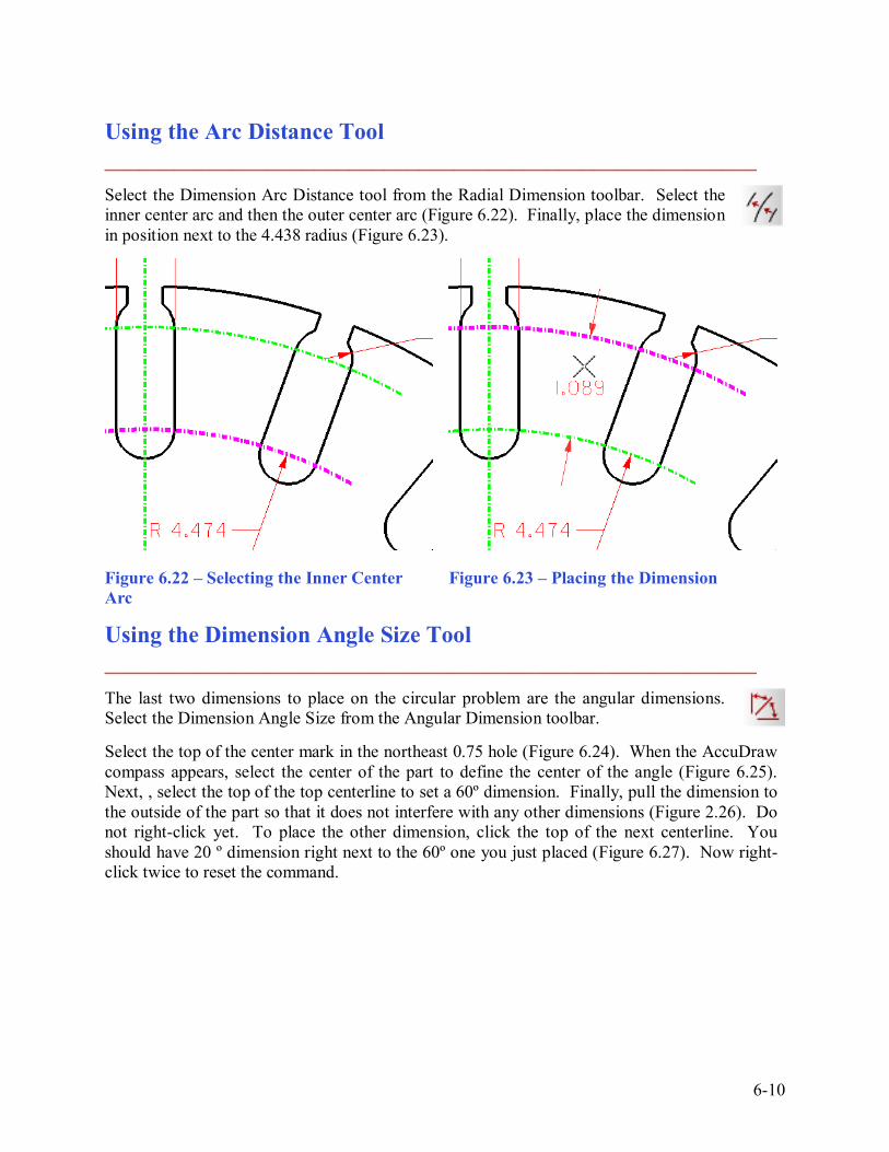
Using the Arc Distance Tool ________________________________________________________ Select the Dimension Arc Distance tool from the Radial Dimension toolbar. Select the inner center arc and then the outer center arc (Figure 6.22). Finally, place the dimension in position next to the 4.438 radius (Figure 6.23).
Figure 6.22 � Selecting the Inner Center Arc
Figure 6.23 � Placing the Dimension
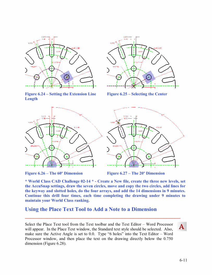
Using the Dimension Angle Size Tool ________________________________________________________ The last two dimensions to place on the circular problem are the angular dimensions. Select the Dimension Angle Size from the Angular Dimension toolbar. Select the top of the center mark in the northeast 0.75 hole (Figure 6.24). When the AccuDraw compass appears, select the center of the part to define the center of the angle (Figure 6.25). Next, , select the top of the top centerline to set a 60º dimension. Finally, pull the dimension to the outside of the part so that it does not interfere with any other dimensions (Figure 2.26). Do not right-click yet. To place the other dimension, click the top of the next centerline. You should have 20 º dimension right next to the 60º one you just placed (Figure 6.27). Now right-click twice to reset the command.
6-11
Figure 6.24 � Setting the Extension Line Length
Figure 6.25 � Selecting the Center
Figure 6.26 � The 60º Dimension Figure 6.27 � The 20º Dimension * World Class CAD Challenge 02-14 * - Create a New file, create the three new levels, set the AccuSnap settings, draw the seven circles, move and copy the two circles, add lines for the keyway and slotted holes, do the four arrays, and add the 14 dimensions in 9 minutes. Continue this drill four times, each time completing the drawing under 9 minutes to maintain your World Class ranking.
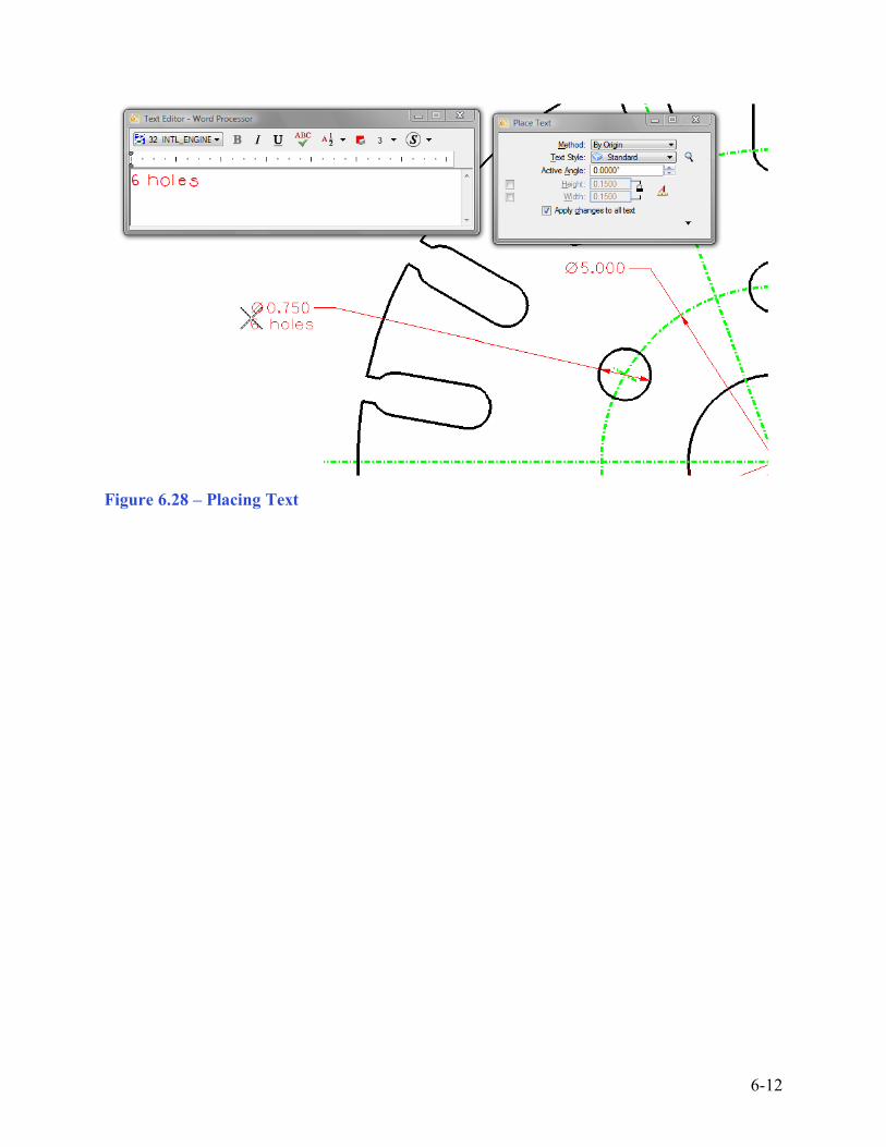
Using the Place Text Tool to Add a Note to a Dimension ________________________________________________________ Select the Place Text tool from the Text toolbar and the Text Editor � Word Processor will appear. In the Place Text window, the Standard text style should be selected. Also, make sure the Active Angle is set to 0.0. Type �6 holes� into the Text Editor � Word Processor window, and then place the text on the drawing directly below the 0.750 dimension (Figure 6.28).
6-12
Figure 6.28 � Placing Text
6-13
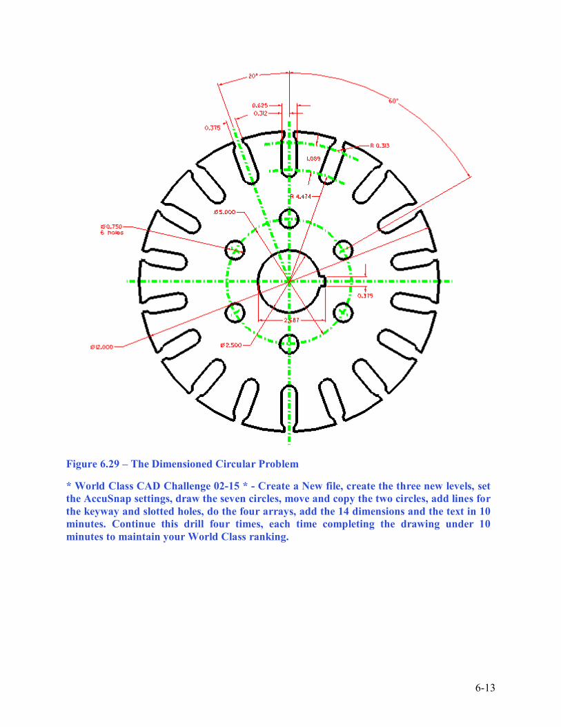
Figure 6.29 � The Dimensioned Circular Problem * World Class CAD Challenge 02-15 * - Create a New file, create the three new levels, set the AccuSnap settings, draw the seven circles, move and copy the two circles, add lines for the keyway and slotted holes, do the four arrays, add the 14 dimensions and the text in 10 minutes. Continue this drill four times, each time completing the drawing under 10 minutes to maintain your World Class ranking.