Embed Size (px)
Citation preview

Dimensioning and Tolerancing

Learning Objectives• After completing this chapter, you will
– Explain ASME Y14.5M
– Identify common dimensioning systems
– Understand fundamental tenets of dimensioning
– Apply general, specific, and delta notes
– Apply draft angles
– Understand symbology
• Surface finish
• Tolerancing

Part I
Definitions and ASME Y14.5M

ASME Y14.5M• Standard adopted by ANSI
• Published by ASME
– 345 East 47th Street, New York, NY 10017
• Entitled “Dimensioning and Tolerancing”
• ASME Y14.1M
– Controls general dimensional tolerances
• In titleblock
• In general notes

Definitions• Size dimension
– May be placed directly on feature
– May be a note
– Identify length, width, or depth of feature
• Location dimension
– Relationship of features of an object

Definitions• Actual size
– Produced size
– Measured after production
• Allowance
– Tightest possible fit between two mating parts
– MMC(external feature)-MMC(internal feature)
• Basic dimension
– Theoretically exact size
– Rectangle around numerical value

Definitions• Bilateral tolerance
– Variance in two directions from specified
dimension
• Datum
– Theoretically exact surface, plane, axis, center
plane, point
• Dimensions for related features established

Definitions• Datum feature
– Actual feature of part• Used to establish a datum
• Dimension
– Numerical value• Describes size, shape, location, geometry, or
surface texture
• Feature
– Any physical portion of an object

Definitions• Geometric tolerance
– Control form, profile, orientation, location, and
runout
• Least material condition (LMC)
– Lower limit for external feature
– Upper limit for internal feature

Definitions• Limits of dimension
– Largest and smallest boundaries
– Related to tolerance of dimension
• Maximum material condition (MMC)
– Largest limit for external feature
– Smallest limit for internal feature

Definitions• Nominal size
– General identification
• Stock size
• Thread diameter
• Reference dimension
– Used for information purposes only
– Without tolerances
– Enclosed in parentheses

Definitions• Specified dimension
– From which limits are calculated
• Tolerance
– Total permissible variation in size or location
• Unilateral tolerance
– Variation in only one direction

Definitions• Notes
– Identify size with more than a numerical value
– Two types
• General
– Relate to entire drawing
• Local
– Connected to specific features

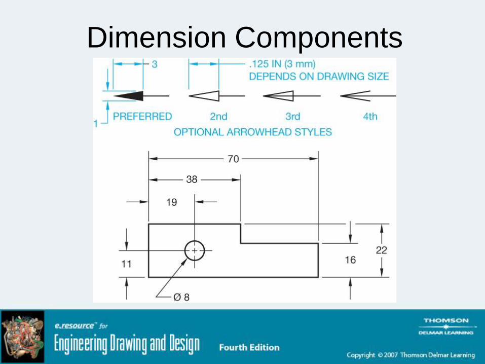
Dimension Components

Dimension Components• Dimension lines
– Indicate length of dimension
– Thin lines capped with arrowheads
– Broken along length to provide space for
dimension value
• Gap is commonly .06 inch
• Angular dimension line
– Arc with center of the arc from vertex of angle

Dimension Components• Dimension text
– Normally .12 inch high
– Centered in dimension line space
• Leader line
– Thin line
– Connects specific note to feature
– Any angle between 15 and 75 degrees
• Preferably 45 degrees

Dimension Components• Arrowheads
– Cap dimension line and leader line
– Three times as long as high• .125 inch long typically
• Extension lines
– Establish extent of dimension
– Thin lines
– Offset .06 inch from object
– Extend .12 inch past last dimension line
Dimension Components

Dimension Components• Center dash
– Part of centerline
– Thin line
– Drawn .12 inch
• Centerline space
– Commonly .06 inch
– Space between long and short dashes of
centerline
Part II
Dimensioning Systems

Unidirectional Dimensioning• Commonly used in mechanical drafting
• All numbers, figures, and notes read from
bottom
– Lettered horizontally on page

Unidirectional Dimensioning

Aligned Dimensioning• Read from
– Bottom
• Horizontal dimension
– Right
• Vertical dimension

Aligned Dimensioning

Tabular Dimensioning• Size and location dimensions in table
– X, Y, and Z axes defined
– Features related to table by symbols

Tabular Dimensioning

Arrowless Dimensioning• Ordinate dimensioning
• Features keyed to a table
• Location dimensions
– Established with extension lines
• Determined by datums

Arrowless Dimensioning
Chart Drawings• Used when
– Part or assembly has one or more dimensions
that change
• Dependent on application
• Variable dimension labeled with letter
• Commonly used in vendor or specification
catalogs

Chart Drawings

Part III
Dimensioning Rules

Decimal Points• Leading zeros
– Only for metric values less than one
• E.g., 0.08 mm
• Specified dimension
– Same number of decimal places as tolerance
Fractions• Separate whole numbers from fractions with
dash
– E.g. 1-5/8, not 1 5/8
• Use stacked fractions whenever possible

Chain Dimensioning• Point-to-point dimensioning
– Dependent on previous dimension(s)
– Avoid tolerance buildup
• Overall dimension
– Critical
– Stands independent in relationship to other
dimensions
• Let one dimension “float”
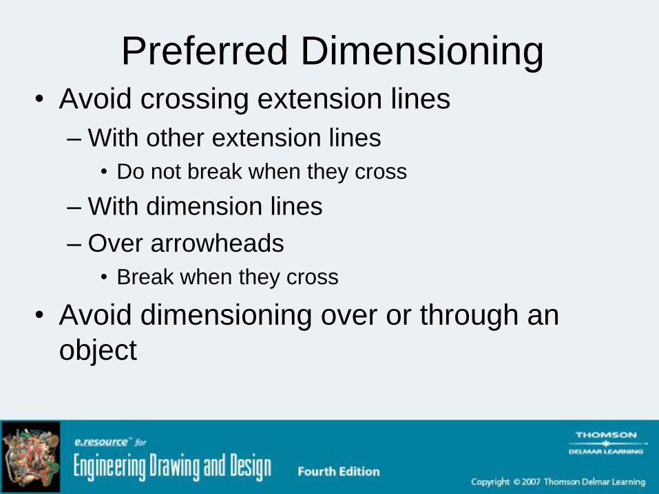
Preferred Dimensioning• Avoid crossing extension lines
– With other extension lines
• Do not break when they cross
– With dimension lines
– Over arrowheads
• Break when they cross
• Avoid dimensioning over or through an
object

Preferred Dimensioning• Avoid
– Dimensioning to hidden features
– Unnecessarily long extension lines
– Using object lines as extension lines
• Dimension between views when possible
• Group adjacent dimensions
• Dimension to view that provide best shape
description
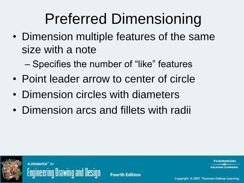
Preferred Dimensioning• Dimension multiple features of the same
size with a note
– Specifies the number of “like” features
• Point leader arrow to center of circle
• Dimension circles with diameters
• Dimension arcs and fillets with radii

Location Dimensions• Rectangular shapes
– Located to sides
• Symmetrical features
– Located to centerline or centerplane
• Cylindrical features
– Given to center of feature
– Dimension in view where they appear as circles
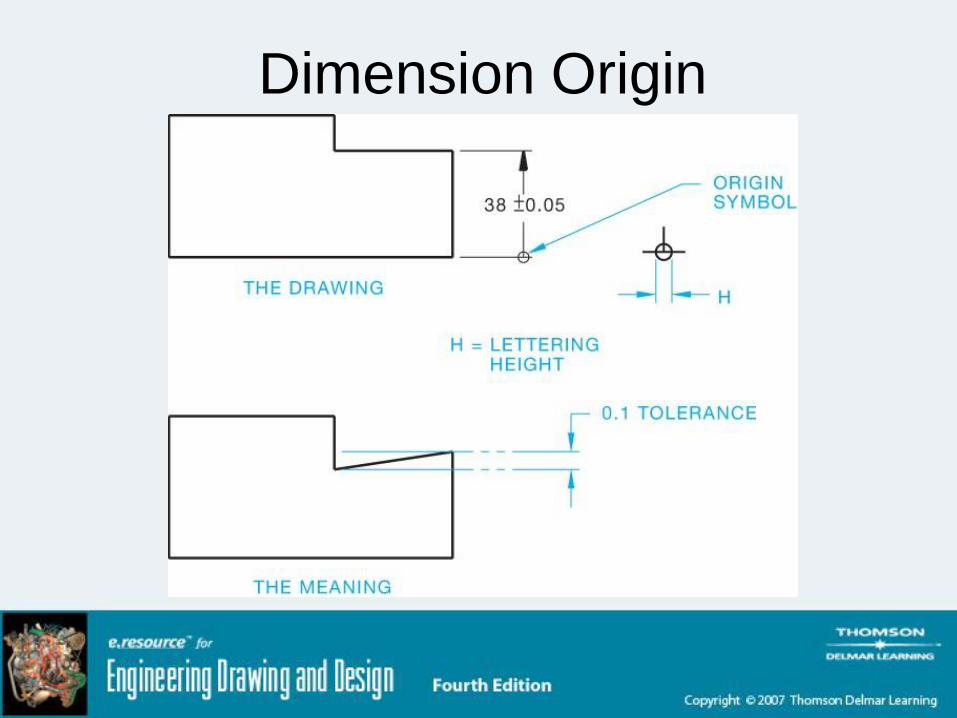
Dimension Origin

Part IV
Notes and Symbols

Counterbore• Machine a diameter below part surface
– Bolt head may be recessed
• Symbol
– Same as for spotface

Counterbore

Countersink• Counterdrill
• Recess head of fastener below part surface

Countersink

Slots• Full radius
– Dimension one of three ways
• End radius > feature width
– Dimension end radii
– Dimension feature width
– Dimension feature length

Slots
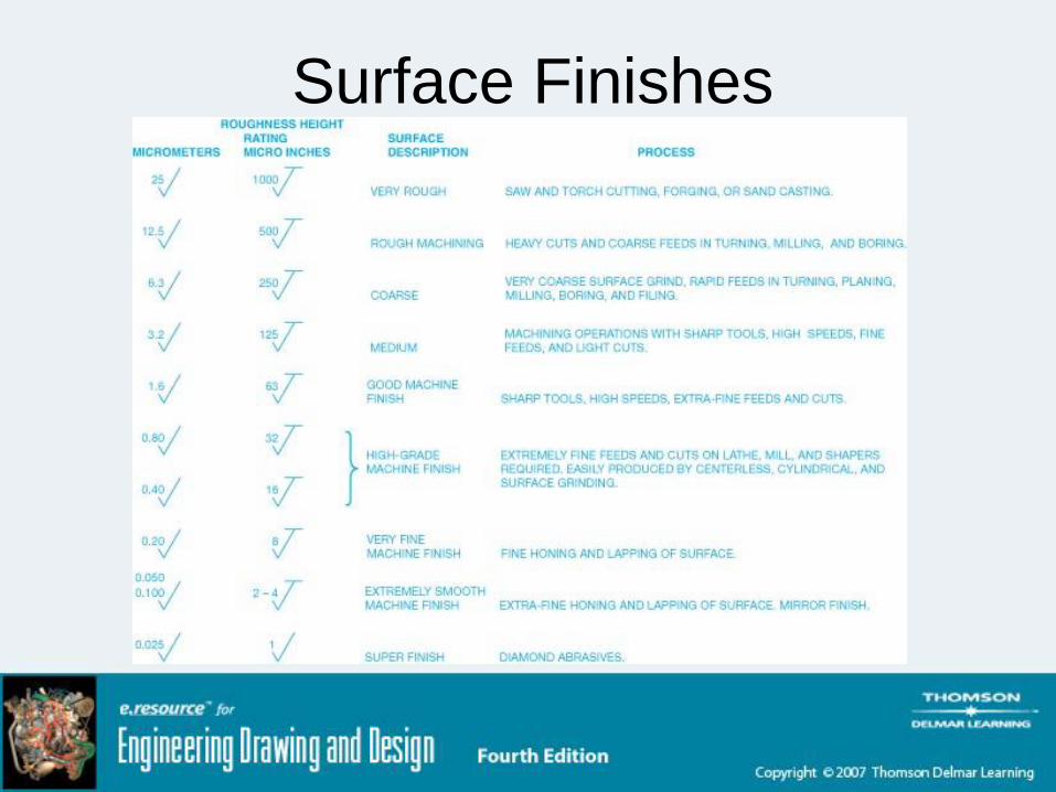
Surface Finishes• When object surfaces are machined to
certain specification
• May appear in a general note
• May be connected to specific surface with
leader
• FAO
– Finish all over

Surface Finishes
Surface Finishes

General Notes• Material specifications
• Dimensions
• General tolerances
• Confidential note, copyrights, patents
• Drawn by
• Scale
• Date
• Part name

General Notes• Drawing size
• Part number
• Number of revisions
• Type of projection (first or third)
• Standard reference (e.g., ANSI/ASME)
• General machining, finish, or paint specifications
• Identification of “like” features
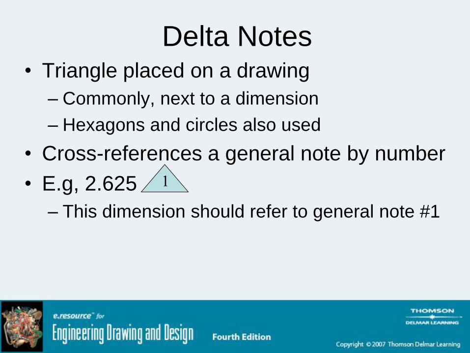
Delta Notes• Triangle placed on a drawing
– Commonly, next to a dimension
– Hexagons and circles also used
• Cross-references a general note by number
• E.g, 2.625
– This dimension should refer to general note #1
1

Part V
Tolerancing

Calculating Tolerances• For example
– 22.0 ± 0.1
• Upper limit
– 22.1
• Lower limit
– 21.9
• Tolerance
– 0.2

Fit Tables - ANSI• RC
– Running clearance
• LC– Locational clearance
• LT– Transitional clearance
• LN– Locational interference
• FN– Force fit

Fit Tables - ISO• Hole basis
– Clearance Fit
• H11/c11
• H9/d9
• H8/f7
• H7/g6
• H7/h6

Fit Tables - ISO• Hole basis
– Transition fit
• H7/k6
• H7/n6
– Interference fit
• H7/p6
• H7/s6
• H7/u6
Summary• Use conventional dimensioning practices
– Continuity
– Accuracy
– Ease of interpretation
• Specify tolerances that are appropriate for
part application and machining ability