Embed Size (px)
Citation preview

© DIGITAL VISION
The advent of phased array radars and space-time adaptive processing has given radardesigners the ability make radars adaptable on receive. The current state of radar technolo-gy allows the transmission of wavefields that vary across space, time, and frequency andthat can be changed in rapid succession. The ability to exploit space-time adaptive process-ing is limited by the computational power available at the receiver, and increased flexibility
on transmission only exacerbates this problem unless the waveforms are properly designed to simplifyprocessing at the receiver.
Sixty years ago, efforts by Marcel Golay to improve the sensitivity of far infrared spectrometry led tothe discovery of pairs of complementary sequences. Shortly thereafter, Welti proposed to use Golaysequences in radar, but they have found very limited application to date. This article shows that suitably
[Robert Calderbank, Stephen D. Howard, and Bill Moran]
Waveform Diversity in RadarSignal Processing
Digital Object Identifier 10.1109/MSP.2008.930414
IEEE SIGNAL PROCESSING MAGAZINE [32] JANUARY 2009 1053-5888/09/$25.00©2009IEEE
[A focus on the use and control of degrees of freedom]
Authorized licensed use limited to: WASHINGTON UNIVERSITY LIBRARIES. Downloaded on February 17, 2009 at 12:12 from IEEE Xplore. Restrictions apply.
transmitted and processed, radar waveforms based on Golaysequences provide new primitives for adaptive transmission thatenable better detection and finer resolution, while managingcomputational complexity at the receiver.
DEGREES OF FREEDOM AND RADAR SIGNAL PROCESSINGAdvances in active sensing are enabled by the ability to controlnew degrees of freedom, and each new generation of radar plat-forms requires fundamental advances in radar signal processing[20], [30]. Later generations are distinguished by the increaseddimensionality of the illumination pattern across the elementsof the array (whether distributed or collocated), across availablepolarizations, and over time.
The simplest radars scan the antenna beam in azimuth andform an image of the environment by integrating one-dimen-sional views. Variation of pulse-repetition intervals (PRIs)resolves ambiguities, and processing of all ranges and Dopplershifts is simultaneous. Space-time adaptive processing (STAP)retains the single transmit beam direction but is electronicallysteerable, and digitization on receive enables adaptive beam-forming to eliminate interference [30]. Advanced phased arraysintroduce broad waveform adaptability (time, space, frequency,and polarization) leading to full distributed aperture function-ality. These radars are able to transmit simultaneously in alldirections, collect returns at multiple locations, and employwaveform adaptation to simplify signal processing.
PHYSICAL DIVERSITY: SPACE AND POLARIZATIONA fundamental objective of radar engineers is the design ofwaveforms that effectively utilize radar resources (transmittersand receivers) that are distributed spatially in polarization, time,and frequency. To comprehend the physical picture, assume Nfully polarimetric transmit and M fully polarimetric receiveantennas. Also assume narrowband transmission, where thewaveforms take the form of relatively slow modulations on acarrier frequency at each transmitter, so that the scatteringcross section is constant in frequency across the bandwidth ofthe waveform. Given a single scatterer in the far field of each ofthe transmitters, the transmitted signals arrive at the scattereras plane waves, with a direction of arrival κκκn and complex polar-ization vector εεεn, which itself may be a slowly varying functionof time. The radar cross section of the scatterer, σ(k, e |κκκ, εεε), isthe relative amplitude at which an incoming electromagnetic(EM) plane wave from direction κκκ and with polarization vector εεεis scattered to an outgoing plane wave in the far field with prop-agation direction k and polarization e. We consider three scenar-ios, presenting very different design challenges:
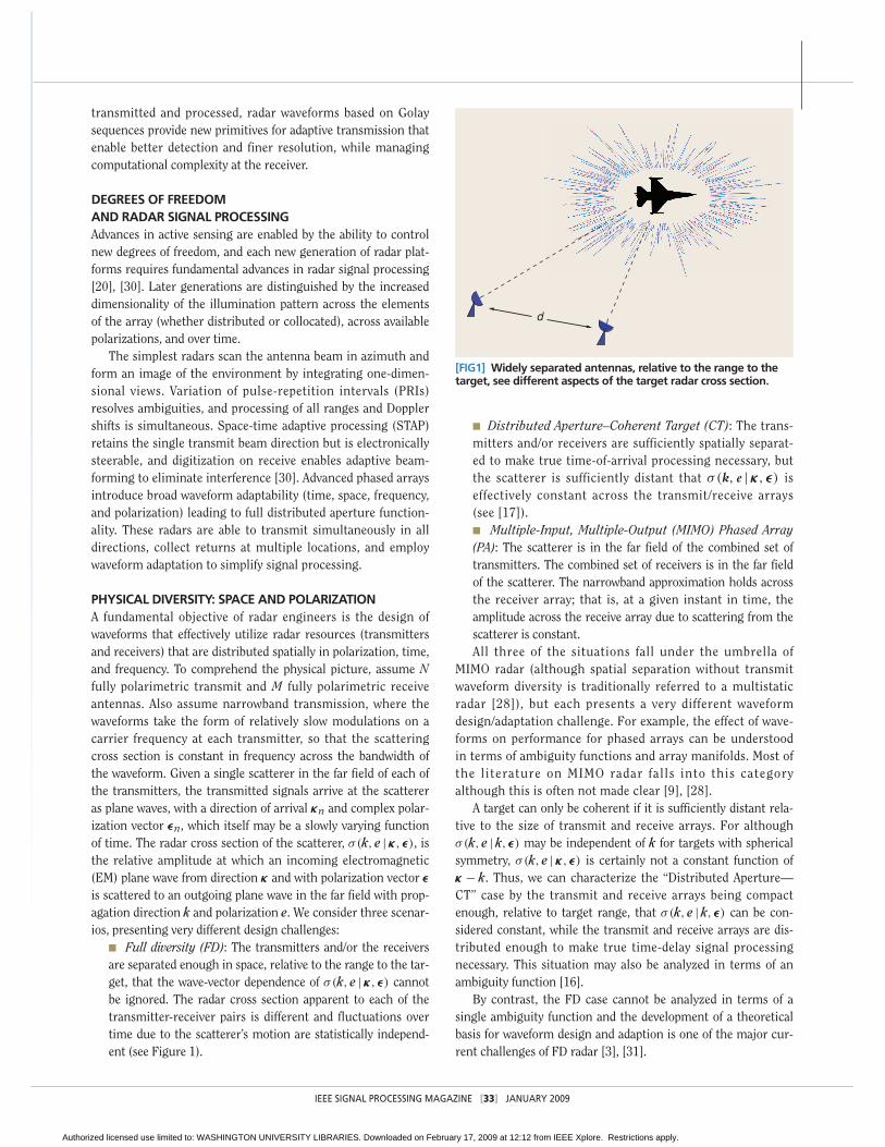
■ Full diversity (FD): The transmitters and/or the receiversare separated enough in space, relative to the range to the tar-get, that the wave-vector dependence of σ(k, e |κκκ, εεε) cannotbe ignored. The radar cross section apparent to each of thetransmitter-receiver pairs is different and fluctuations overtime due to the scatterer’s motion are statistically independ-ent (see Figure 1).
■ Distributed Aperture–Coherent Target (CT): The trans-mitters and/or receivers are sufficiently spatially separat-ed to make true time-of-arrival processing necessary, butthe scatterer is sufficiently distant that σ(k, e |κκκ, εεε) iseffectively constant across the transmit/receive arrays(see [17]).■ Multiple-Input, Multiple-Output (MIMO) Phased Array(PA): The scatterer is in the far field of the combined set oftransmitters. The combined set of receivers is in the far fieldof the scatterer. The narrowband approximation holds acrossthe receiver array; that is, at a given instant in time, theamplitude across the receive array due to scattering from thescatterer is constant.All three of the situations fall under the umbrella of
MIMO radar (although spatial separation without transmitwaveform diversity is traditionally referred to a multistaticradar [28]), but each presents a very different waveformdesign/adaptation challenge. For example, the effect of wave-forms on performance for phased arrays can be understoodin terms of ambiguity functions and array manifolds. Most ofthe literature on MIMO radar falls into this categoryalthough this is often not made clear [9], [28].
A target can only be coherent if it is sufficiently distant rela-tive to the size of transmit and receive arrays. For althoughσ(k, e | k, εεε) may be independent of k for targets with sphericalsymmetry, σ(k, e |κκκ, εεε) is certainly not a constant function ofκκκ − k. Thus, we can characterize the “Distributed Aperture—CT” case by the transmit and receive arrays being compactenough, relative to target range, that σ(k, e | k, εεε) can be con-sidered constant, while the transmit and receive arrays are dis-tributed enough to make true time-delay signal processingnecessary. This situation may also be analyzed in terms of anambiguity function [16].
By contrast, the FD case cannot be analyzed in terms of asingle ambiguity function and the development of a theoreticalbasis for waveform design and adaption is one of the major cur-rent challenges of FD radar [3], [31].
IEEE SIGNAL PROCESSING MAGAZINE [33] JANUARY 2009
[FIG1] Widely separated antennas, relative to the range to thetarget, see different aspects of the target radar cross section.
d
Authorized licensed use limited to: WASHINGTON UNIVERSITY LIBRARIES. Downloaded on February 17, 2009 at 12:12 from IEEE Xplore. Restrictions apply.

WAVEFORM DIVERSITYModern radars are increasinglybeing equipped with arbitrarywaveform generators that enablesimultaneous transmission of dif-ferent waveforms from differentpolarimetric antennas, even on apulse-to-pulse basis. The availabledesign space encompasses spatiallocation, polarization, time, andfrequency. Thus, although wemust respect time and bandwidth constraints, the number ofpossibilities is vast.
The complexity of the design problem motivates synthesis ofwaveforms from components having smaller time-bandwidth prod-uct and complementary properties. A waveform is assembled bysequencing the components in time and/or stacking them in fre-quency in such a way that they have negligible overlap. Withthis approach, the waveform design problem splits into twosimpler pieces: the design of components that complementeach other, and the design of time-frequency combinations ofthese components with desirable properties. Another advantageof modularity is that the time-frequency combinations can bevaried in time to enable adaptive control of the radar’s opera-tion. Examples of this approach include pulse trains of orthogo-nal waveforms (separation in time) and what is often referred toas orthogonal frequency division multiplexing (OFDM) radar,where waveforms are separated in frequency.
THE RADAR AMBIGUITY FUNCTIONFor simplicity, we postpone consideration of the spatial andpolarization degrees of freedom and focus on time/frequencyaspects (collocated transmitter and receiver). The radar ambigui-ty function is the standard and convenient device to express blur-riness of a scene as a result of illumination by a radar waveformand processing of the return by correlating with the transmittedwaveform—matched filtering [2], [13], [29]. This optimizes thepost-processing signal-to-noise ratio (SNR). The ambiguity func-tion is, in a very real sense, the point-spread function for therange-velocity plane. Provided the transmitter and receiver arecollocated, the ambiguity function for a waveform w is
Aw(x, f ) =∫ ∞
−∞w(t)w(t − x)e2π if t dt, (1)
and, for multiple scatterers at varying ranges and radial veloci-ties, the processed received signal is obtained by taking a linearcombination of shifts of the ambiguity at these ranges andvelocities. The scalars involved in this linear combination arethe radar cross sections of the scatterers. Moyal’s identity [13]captures the fundamental limits on this blurriness.Mathematically, it is expressed as
∫ ∞
−∞
∫ ∞
−∞|Aw(t, f )|2 dtdf =
(∫ ∞
−∞|w(t)|2 dt
)2
. (2)
More intuitively, it puts a lowerbound on the volume under thesquared ambiguity surface as afunction of the energy in thesignal. It encapsulates, in aslightly dif ferent guise, theHeisenberg uncertainty princi-ple. It should be clear thatdesign of the ambiguity, orrather of the waveform, toachieve a given ambiguity with-
in the limitations imposed by Moyal’s identity is an impor-tant issue for the radar engineer. The aim should be tomove the inevitable volume under the (squared) ambiguitysurface to regions where it matters least for the operationaltask of the radar.
It is important to bear in mind that the ambiguity is that ofthe waveform in its entirety. Choosing to transmit multiplepulses over time or across multiple frequency bands, andprocess in this way, or even in some other linear way, similarlimitations will hold. In radar theory, it is customary to regard awaveform as a signal modulated onto a carrier and to separatethe carrier modulation and demodulation processes from theambiguity treatment. We want to emphasize that the carrieralso plays a role in the ambiguity, and care has to be exercised indiscussion of the situation where several carriers are involved[5]. We will return to this in later examples.
Why would we want to separate signals over time or overfrequency? After all, if the correct approach is to calculate theambiguity for the waveform in its entirety, then there wouldappear to be no reason to separate. Quite simply, separationsimplifies design of waveforms. We hope this will becomeclearer when we discuss issues associated with Doppler pro-cessing, where the problem of ambiguity design is simplifiedby an approximate separation of the range and Doppler meas-urement problems. This is possible because, for short enoughwaveforms and for scatterers moving slowly enough, Dopplercan be ignored as an intrapulse effect, and only has signifi-cance between pulses. This separation is at the heart of con-ventional processing techniques for pulse Doppler radars.
By choosing to separate waveforms in time, in frequency,or both, we modularize the design problem and reap theusual advantages attached to modularity in other areas ofengineering. Unfortunately, there is a cost: ultimately wecannot escape Moyal. In the case of time or frequency sepa-ration of waveforms, this cost is related to the presence ofthe carrier. In particular, when the carrier is incorporatedinto the waveform in the calculation of the ambiguity, aphase factor emerges that is dependent on the range and/orDoppler of the scatterer.
To see this effect in the time-separated case, assume twowaveforms w1 and w2 of short duration relative to their timeseparation T. The transmitted pulse is
w(t) = w1(t) + w2(t − T). (3)
IEEE SIGNAL PROCESSING MAGAZINE [34] JANUARY 2009
A FUNDAMENTAL OBJECTIVE OFRADAR ENGINEERS IS THE DESIGN
OF WAVEFORMS THAT EFFECTIVELYUTILIZE RADAR RESOURCES
(TRANSMITTERS AND RECEIVERS)THAT ARE DISTRIBUTED SPATIALLY
IN POLARIZATION, TIME, ANDFREQUENCY.
Authorized licensed use limited to: WASHINGTON UNIVERSITY LIBRARIES. Downloaded on February 17, 2009 at 12:12 from IEEE Xplore. Restrictions apply.

The ambiguity calculation for a scatterer at a distance R, mov-ing at a radial velocity of v, is then, up to a phase factor andneglecting the range-aliased terms
Aw
(τ − 2R
c, φ − 2 fcv
c
)= Aw1
(τ − 2R
c, φ − 2 fcv
c
)
+ e−2π i(φ−2 fcv/c)TAw2
(τ − 2R
c, φ − 2 fcv
c
). (4)
This expression makes it clear that the two ambiguities have arelative Doppler dependent phase factor that precludes additionof the ambiguities (see Figure 2).
If the waveforms are separated in frequency,
w(t) = w1(t) + e2π ifstw2(t), (5)
where fs is the frequency separation, then the correspondingcalculation, this time neglecting out-of-band Doppler termsgives
Aw
(τ − 2R
c, φ − 2 fc
c
)= Aw1
(τ − 2R
c, φ − 2 fcv
c
)
+ e−2π ifs(τ−2R/c) Aw2
(τ − 2R
c, φ − 2 fcv
c
). (6)
Again a relative phase factor, this time dependent on the rangeof the scatterer, prevents the result being a sum of ambiguities.
It is important to recognize from thesecalculations that the ambiguity of the fullwaveform is never the sum of the ambiguityfunctions of its frequency- or time-separatedcomponents. It is simply not possible torealize a summed or composite ambiguityfunction in a radar context. Indeed, con-ventional Doppler processing is a methodof exploiting the above phase shift whenthe individual waveforms are separated intime, and of using it to estimate the radi-al velocity of a scatterer, and separatemoving scatterers from stationary ones.
Matched filtering optimizes SNR as wehave stated, but there are many radarapplications where clutter is more of anissue than noise. It is appropriate to treatclutter according to a noise model ifnothing is known about it. But onceinformation is available, either through amodel for the kind of clutter (for exam-ple, sea or land) or from measurementstaken prior to the current one (or both),the information available can be used toconstrain the clutter, and thereby buyimprovement in radar performance bycareful choice of the waveform.
POLARIZATIONAs in the spatial case, the radar cross section of an extended tar-get, such as an aircraft or a ship, is highly sensitive to the angleof incidence and angle of view of the sensor (see [19, Sect.2.7–2.8]). In general, the reflection properties that apply to eachpolarization component are also different and indeed, reflectioncan change the direction of polarization. Thus, polarimetricradars are able to obtain the scattering tensor of a target
��� =(
σVV σVH
σHV σHH
), (7)
where σVH denotes the target scattering coefficient into thevertical polarization channel due to a horizontally polarizedincident field. Target detection is enhanced by concurrentrather than serial access to the cross-polarization compo-nents of the scattering tensor, which varies more rapidly instandard radar models used in target detection and tracking[18], [26] than in models used in remote sensing or syntheticaperture radar [12], [22].
In fact, what is measured is the combination of three matrices
H =(
hVV hVH
hHV hHH
)= CRx���CTx, (8)
where CRx and CTx correspond to the polarization couplingproperties of the transmit and receive antennas, whereas ���results from the target. In most radar systems the transmit and
IEEE SIGNAL PROCESSING MAGAZINE [35] JANUARY 2009
[FIG2] Cancellation rather than complementarity. Frequency separated returns canceldue to range dependent phases. The precise effect on the sum of the returns dependson the range of the target modulo the chip length for the phase-coded pulse.
0 100 200 300 400 500 600 700 800 9000
50
100
150
200Range = 1506.0, Return for Channel Number 1
0 100 200 300 400 500 600 700 800 9000
50
100
150
200Range = 1506.0, Return for Channel Number 2
0 100 200 300 400 500 600 700 800 9000
20
40
60
80Range = 1506.0, Sum of Returns
Authorized licensed use limited to: WASHINGTON UNIVERSITY LIBRARIES. Downloaded on February 17, 2009 at 12:12 from IEEE Xplore. Restrictions apply.

receive antennas are common, and so the matrices CTx and CRx
are conjugate. The cross-coupling terms in the antenna polar-ization matrices are clearly frequency- and antenna-geometrydependent but for the linearly polarized case this value is typi-cally no better than about −20 dB.
Following [10] we propose to use both polarization modesto transmit four phase-coded waveforms w1
H, w1V, w2
H, w2V . On
each polarization mode, we transmit two phase-coded pulsesseparated by a time interval T orpulse-repetition interval (PRI).Thus, we transmit a first pair ofwaveforms w 1 = (w1
V, w1H) fol-
lowed by a second pair of wave-forms w 2 = (w2
V, w2H) . This
passes through the channeldefined by the target and anten-nas, to produce vectorsr j = Hw j + z j at the receiver,where the z j are white Gaussiannoise. We employ a paraunitaryfilter bank (see [21]) to coordinate transmission over the V andH channels; that is, we define
w2H = w̃1
V (9)
w2V = −w̃1
H, (10)
where ̃· denotes complex conjugate time-reversal. Conversion of all of the time-indexed sequences into the z-
transform domain, and combination to form matrices:
R(z) = (r 1(z)T, r 2(z)T), and W(z) = (w 1(z)T, w 2(z)T) yields
R(z) = H(z)W(z) + Z(z). (11)
Our aim is to extract H(z), and this is facilitated by the choice ofW(z) to be unitary (a paraunitary filter bank), which is equivalent to
w1V(z)w̃1
V(z) + w1H(z)w̃1
H(z) = 2NzN−1, (12)
where N − 1 is the degree of thepolynomial w1(z). Polynomialswith coefficients that are rootsof unity and that satisfy (12) arecomplex Golay complementarypolynomials [8], and their coef-ficients are Golay complemen-tary sequences, which arecharacterized by the propertythat the sum of the two auto-correlation functions vanishes
at all (integer) delays other than zero (see Figure 3).
corrwV(k) + corrwH(k) = 2Nδ(k). (13)
The classical Golay pairs, with coefficients ±1, were intro-duced by Golay to improve the sensitivity of far-infraredspectrometry [6]–[8], [15]. Golay pairs are widely studied inthe radar and communications literature both as pairs andindividually [27]. As individual waveforms they have favor-able auto-correlation properties. These pairs have been con-
structed, in particular, with lengths 2n
for all positive integers n [25].
SPATIAL DIVERSITYThe concepts developed in the precedingsection for polarization extend naturallyto spatial diversity. Transmission of differ-ent waveforms from different radar ele-ments (either distributed or collocated)over multiple PRIs has the effect of coor-dinatizing space. Leaving aside multipathissues, every point of space effectivelyreceives a differently delayed combinationof the waveforms, and so reflects backinto the receivers this combination. Byprocessing with several suitably chosenfilter banks in the receivers, it is possibleto separate the waveforms and to extractthe position of the scatterers from thedelays. In effect a multi-dimensionalmatched filter is performed.
At its simplest, such a scheme mightwork by time-separating very short pulsesfrom each transmitter and collecting thedelays at each receiver. This has the[FIG3] The Golay Property after low-pass filtering.
Baseband Golay 1 Baseband Golay 2
Baseband Autocorr 2Baseband Autocorr 1
Baseband Autocorr Sum
2
1
0
−1
−50
−80−50
−60 −40 −20
−20−50
−2
−20
2
1
0
−1
−2
60
40
20
0
60
40
20
0
100
50
0
0 20 40 60 80
0 20 40 600 20 40 60
0 500 50
IEEE SIGNAL PROCESSING MAGAZINE [36] JANUARY 2009
MODERN RADARS ARE INCREASINGLYBEING EQUIPPED WITH ARBITRARY
WAVEFORM GENERATORS THATENABLE SIMULTANEOUS
TRANSMISSION OF DIFFERENTWAVEFORMS FROM DIFFERENT
POLARIMETRIC ANTENNAS, EVENON A PULSE-TO-PULSE BASIS.
Authorized licensed use limited to: WASHINGTON UNIVERSITY LIBRARIES. Downloaded on February 17, 2009 at 12:12 from IEEE Xplore. Restrictions apply.
obvious disadvantage of low power and long-time duration.Conventional phased arrays effectively do an approximation tospace-coordinatization by phase shifting transmit sequences andmeasuring (or rather combining) phases of returns in eachreceive element. Multiple PRIs are used to steer beams in differ-ent directions and thereby coordinatize the entire environmentof illumination. Arrays that steer by time-delay rather than phasealso coordinatize space over multiple PRIs in a similar way.
The particular unitary filter bank developed for polarizationdiversity is a special case of a more general construction of uni-tary matrices in which the individual elements are waveforms.Such matrices have been constructed by, for example, Tseng[24] to analyze acoustic surface wave phenomena. The methodsof construction of these matrices of waveforms, as given in[23], are very flexible. Such a scheme can be used in either acollocated array or a distributed array of transmit-receive mod-ules. Rows of the matrix are transmitted from different emittersover multiple PRIs, and the returns are match-filtered at everyreceiver. Collocation of transmitters and receivers is not neces-sary in this application. The array can be distributed, thoughprocessing relies on some measure of coherence. The process-ing over all transmissions is unitary and so is lossless.
One significant feature of this scheme is that multipath canbe tagged. Since the illumination of a given point in space isuniquely determined by its position, returns from that pointhave a unique signature, and even if they arrive at the receiverafter multiple reflections, their origin is still discernible fromthe nature of the return rather than just its time of arrival.
TIME SEPARATION AND DOPPLER RESILIENCEWhy then have Golay complementary sequences not found appli-cation in radar systems? The answer, to quote Levanon [11, pp.264], is: “Although the autocorrelation sidelobe level is zero, theambiguity function exhibits relatively high sidelobes for nonzeroDoppler.” Ducoff and Tietjen [4] states “In a practical application,the two sequences must be separated in time, frequency, orpolarization, which results in decorrelation of radar returns sothat complete sidelobe cancellation may not occur. Hence theyhave not been widely used in pulse compression radars.”
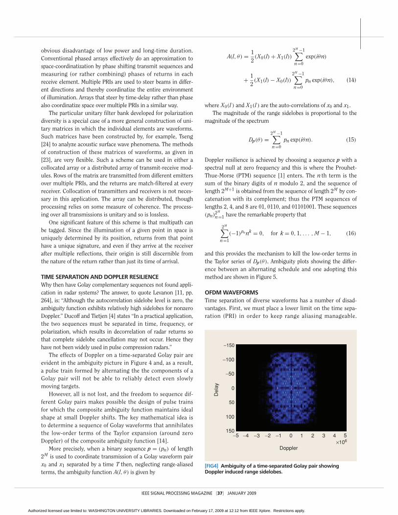
The effects of Doppler on a time-separated Golay pair areevident in the ambiguity picture in Figure 4 and, as a result,a pulse train formed by alternating the the components of aGolay pair will not be able to reliably detect even slowlymoving targets.
However, all is not lost, and the freedom to sequence dif-ferent Golay pairs makes possible the design of pulse trainsfor which the composite ambiguity function maintains idealshape at small Doppler shifts. The key mathematical idea isto determine a sequence of Golay waveforms that annihilatesthe low-order terms of the Taylor expansion (around zeroDoppler) of the composite ambiguity function [14].
More precisely, when a binary sequence p = (pn) of length2M is used to coordinate transmission of a Golay waveform pairx0 and x1 separated by a time T then, neglecting range-aliasedterms, the ambiguity function A(l, θ) is given by
A(l, θ) = 12(X0(l) + X1(l))
2M −1∑n=0
exp(iθn)
+ 12(X1(l) − X0(l))
2M −1∑n=0
pn exp(iθn), (14)
where X0(l ) and X1(l ) are the auto-correlations of x0 and x1. The magnitude of the range sidelobes is proportional to the
magnitude of the spectrum
Dp(θ) =2M −1∑n=0
pn exp(iθn). (15)
Doppler resilience is achieved by choosing a sequence p with aspectral null at zero frequency and this is where the Prouhet-Thue-Morse (PTM) sequence [1] enters. The n th term is thesum of the binary digits of n modulo 2, and the sequence oflength 2M+1 is obtained from the sequence of length 2M by con-catenation with its complement; thus the PTM sequences oflengths 2, 4, and 8 are 01, 0110, and 01101001. These sequences(pn)
2M
n=1 have the remarkable property that
2M∑n=1
(−1)pn nk = 0, for k = 0, 1, . . . , M − 1, (16)
and this provides the mechanism to kill the low-order terms inthe Taylor series of Dp(θ). Ambiguity plots showing the differ-ence between an alternating schedule and one adopting thismethod are shown in Figure 5.
OFDM WAVEFORMSTime separation of diverse waveforms has a number of disad-vantages. First, we must place a lower limit on the time sepa-ration (PRI) in order to keep range aliasing manageable.
[FIG4] Ambiguity of a time-separated Golay pair showingDoppler induced range sidelobes.
Doppler
Del
ay
−5 −4 −3 −2 −1 0 1 2 3 4 5×10⁶
−150
−100
−50
0
50
100
150
IEEE SIGNAL PROCESSING MAGAZINE [37] JANUARY 2009
Authorized licensed use limited to: WASHINGTON UNIVERSITY LIBRARIES. Downloaded on February 17, 2009 at 12:12 from IEEE Xplore. Restrictions apply.

Further, although PTM pulse trains can give increasedDoppler resilience many radar applications demand greaterresilience than is achievable in this manner. The main limita-tion to gaining resilience by the PTM method is that increasedDoppler resilience is gained at the expense of pulse trains ofgreater duration. This must be balanced by the requirementthat the target maintains a relatively constant range andvelocity over the interval of observation.
Frequency separation of the waveforms (OFDM radar)that exploits bandwidth rather than time offers a way for-ward [17]. However, we have seen that a pair of componentwaveforms with complementary autocorrelation or ambigui-ty functions do not retain this complementarity when multi-plexed in frequency, due to the occurrence of a phasedifference between frequency channels that depends on theunknown range to the target and the frequency differencebetween the channels. The individual filter outputs for eachchannels can not be combined coherently. This problem iscommon to all implementations of OFDM radar in which a
set of orthogonal or complementary waveform are transmit-ted on separate frequency channels and then combined afterlinear signal processing.
However, nonlinear signal processing can be used totransform this problem into one that is far more tractable.The idea for a pair of frequency separated component wave-forms is to offset the components equally above and belowthe carrier (see Figure 6).
w(t) = e3π iBtw2(t) + eπ iBtw1(t) +−π iBt/2 w1(t)
+−3π iBt/2 w2(t). (17)
When one component is equally offset above and below thecarrier, the range dependent phase on the two channels arecomplex conjugate and so multiplying the two returns togeth-er gives a quantity that is independent of this phase. Theresult of this nonlinear processing is to produce the sum ofthe squares of the ambiguity functions
[FIG5] (a) The plot of the ambiguity function A(l, θ) (corresponding to the Doppler resilient transmission scheme) versus delay index l and Doppler shift θ , (b) the plot of the ambiguity function A(l, θ) (corresponding to the conventional transmission scheme) versusdelay index l and Doppler shift θ . For a radar with carrier frequency 2.5 GHz and PRI = 100 μs, the Doppler shift range of 0 to 0.05 rad (0.075 rad) corresponds to a maximum target speed of approximately 35 km/h (50 km/h). To cover a larger speed range wecan use this design with a bank of Doppler filters to provide Doppler resilience within an interval around the Doppler frequencyassociated with each filter.
0−10
−70
−5
−60−50−40−30−20
Am
bigu
ity F
unct
ion
[dB
]
5
0.020.04
0.10.08
0.060
Doppler Shift [rad]Delay Index
0−10
−70
−5
−60−50−40−30−20
5
0.020.04
0.10.080.060
0Doppler Shift [rad]
Delay Index0
(a) (b)
Am
bigu
ity F
unct
ion
[dB
]
[FIG6] Frequency separation scheme.
eπiBtφ0(t )
e2πiBt /3φ1(t )
e−πiBtφ0(t )
e−2πiBt /3φ1(t )
e−2πiBτ/3 φ1(t )φ1(t − τ)dt
e−πiBτ φ0(t )φ0(t − τ)dt
eπiBτ φ0(t )φ0(t − τ)dt
e2πiBτ/3 φ1(t )φ1(t − τ)dt
×
×
+2
+
�
φ0(t )φ0(t − τ)dt)(� φ1(t )φ1(t − τ)dt)2
(����
IEEE SIGNAL PROCESSING MAGAZINE [38] JANUARY 2009
Authorized licensed use limited to: WASHINGTON UNIVERSITY LIBRARIES. Downloaded on February 17, 2009 at 12:12 from IEEE Xplore. Restrictions apply.

Aw0(τ, φ)2 + Aw1(τ, φ)2. (18)
The problem then becomes one of finding component wave-forms for which the squares of their ambiguity or autocorrela-tion functions are complementary.
In order to recover the Golay complementary behavior in thisscheme, we need to find quaternary-sequences with the property that
corr2w1
(k) + corr2w2
(k) = 2N 2δ(k). (19)
We refer to sequences and the corresponding waveforms hav-ing this property as square-Golay complementary. It turnsout that there are many sequences that have this propertywhen N is a power of two. Examples of length 16 are shownin (20) below.
1 1 1 −1 1 1 −1 1 1 1 1 −1 −1 −1 1 −11 1 1 −1 1 1 −1 1 i i i −i −i −i i −i1 i −1 i 1 i 1 −i 1 i −1 i −1 −i −1 i1 i −1 i 1 i 1 −i i −1 −i −1 −i 1 −i −1
(20)
[FIG7] Results of a simulation of a weak target surrounded by several strong clutter returns. The weak return was at 2.37 km (790 samples). Five separate clutter returns were present within overlapping range of the weak return. Each clutter return was 25 dB more powerful than the weak return. (a) The result of Doppler processing a pulse train of 64, length-64, Frank-coded waveforms(chip length: 100 ns, carrier: 10 GHz, PRI: 33 μs) and the zero-Doppler slice. (b) The result of nonlinear Doppler processing a pulse train of64 Doppler resilient OFDM Golay-square waveforms with an initial separation of 10 MHz is increased by 75.8 kHz per pulse along thepulse train.
Delay (Samples)
Fre
quen
cy (
Hz)
0 200 400 600 800 1,000 1,200
−1.5
−1
−0.5
0
0.5
1
1.5
×104 ×104
Delay (Samples)
Fre
quen
cy (
Hz)
0 200 400 600 800 1,000 1,200
−1.5
−1
−0.5
0
0.5
1.5
0 200 400 600 800 1,000 1,2000
10
20
30
40
50
60
70
80
Delay (Samples)
0 200 400 600 800 1,000 1,2000
10
20
30
40
50
60
70
Delay (Samples)
(a) (b)
1
IEEE SIGNAL PROCESSING MAGAZINE [39] JANUARY 2009
Authorized licensed use limited to: WASHINGTON UNIVERSITY LIBRARIES. Downloaded on February 17, 2009 at 12:12 from IEEE Xplore. Restrictions apply.

The second and thirdsequences are square-Golay part-ners for the first and fourthsequences. The second sequence isobtained from the first by multi-plying the last half of the sequenceby i, while the third sequence isobtained from the first by multi-plying the k th element by i k. Thefourth sequence is obtained fromthe first by applying both ofthese transformations. This technique for generating Golay-square sequences from Golay sequences works for a largeclass of Golay sequences. In fact, we can generate Golay-square sequences from almost all length 2m Golay sequencesby transformations related to the above transformation.
At the expense of doubling the transmission bandwidth,we can construct four component waveforms, transmittedover eight channel frequency channels, which have theGolay-square property
corr2w1
(k)+corr2w2
(k)+corr2w3
(k)+corr2w4
(k) = 4N 2δ(k) (21)
over the range of Doppler shifts generally encountered inradar detection. The four sequences in (20) form such a quar-tet. The advantage of frequency separation in obtainingDoppler resilience is that we need only cope with Dopplerphase changes at the waveform chip level. This is in contrastto Doppler resilience for time separation where one mustcope with Doppler phase changes across inter-pulse intervals.Coherent pulse trains of Doppler resilient OFDM pulses canbe used to implement Doppler processing within the nonlin-ear signal processing regime.
So we have waveforms and a nonlinear processingscheme, which for a single target, realizes the promise offrequency-separated Golay complementary waveforms. Wehave produced a thumbtack combined autocorrelation thatis Doppler resilient. A possible drawback is that since thematched-filtered signal is squared during processing, twoclosely-spaced targets produce cross terms in addition tothe returns from the two targets. Our scheme has replacedsidelobes by cross terms. Sidelobes can be mitigated by theuse of amplitude-weighting in the filters, or by post-pro-cessing filter output. Another strategy is to modulate thesignal pulse by a phase code with good autocorrelationproperties. Binary codes and polyphase codes have beenused for this purpose (see [4] and [11]). Manipulation ofcross terms presents an entirely new design space. Thebehavior of cross terms is very different from that of side-lobes. Firstly, the size of the cross terms between two tar-gets depends on the magnitude of both targets. Secondly,whereas waveform sidelobes are difficult to manipulate, theposition of cross terms in range and Doppler can be con-trolled by simple changes in transmission. We illustrate thiswith an example shown in Figure 7, where a modest linear
modulation of the frequencyspacing of OFDM channelsacross a pulse train can be usedto move cross terms to otherpart of the range Dopplerplane, thus revealing a smalltarget. In general, by varyingthe frequency-offset modula-tion from pulse train (coherentprocessing interval) to pulsetrain, we can make the cross
term behave like noise, allowing a multitarget tracker topick out the real targets from clutter interference.
CONCLUSIONSThis article has focused on the use and control of degreesof freedom in the radar illumination pattern. Our basicunit of illumination is a matrix of phase coded waveformsindexed by array element and by the PRI, where the polar-ization of constituent waveforms may vary. Choosing thismatrix to be a unitary filter bank simplifies radar signalprocessing considerably. It also makes it possible to isolateand calibrate methods of controlling individual degrees offreedom before examining them in combination. This focuson unitary filter banks leads to the complementary wave-forms developed by Golay to improve the sensitivity of farinfrared spectrometry and to those developed by Tseng andLiu to analyze acoustic surface wave phenomena. As earlyas 1961, Welti had suggested the use of these complemen-tary waveforms in radar, but to date, this has been preclud-ed by the problems of Doppler induced range sidelobes andrange dependent phase shifts when the waveforms are sepa-rated in frequency.
These roadblocks served as the starting point for researchdescribed in this article. We have described how to designpulse trains for which the composite ambiguity functionmaintains ideal shape at small Doppler shifts. We have alsodescribed new nonlinear signal processing methods thatenable use of complementary waveforms in OFDM radar andprovide Doppler resilience at the chip level. Looking to thefuture, we see unitary filter banks as a new illumination par-adigm that enables broad waveform adaptability across time,space, frequency, and polarization.
ACKNOWLEDGMENTSThe authors would like to acknowledge Doug Cochran, AliPezeshki, Stuart Schwartz, and the anonymous reviewers forhelpful comments and suggestions. This work was supportedin part by the National Science Foundation under Grant0701226, the Department of the Navy, Office of Naval Researchunder Grant N00014-02-100398, and the Air Force Office ofScientific Research under MURI Grant AFOSR-FA9550-05-1-0443. This work is proudly supported by International ScienceLinkages established under the Australian government’s innova-tion statement, “Backing Australia’s ability.”
IEEE SIGNAL PROCESSING MAGAZINE [40] JANUARY 2009
ADVANCES IN ACTIVE SENSINGARE ENABLED BY THE ABILITY TO
CONTROL NEW DEGREES OFFREEDOM, AND EACH NEW
GENERATION OF RADARPLATFORMS REQUIRES
FUNDAMENTAL ADVANCES INRADAR SIGNAL PROCESSING.
Authorized licensed use limited to: WASHINGTON UNIVERSITY LIBRARIES. Downloaded on February 17, 2009 at 12:12 from IEEE Xplore. Restrictions apply.

IEEE SIGNAL PROCESSING MAGAZINE [41] JANUARY 2009
AUTHORS Robert Calderbank ([email protected]) received theB.Sc. degree in 1975 fromWarwick University, England,M.Sc. degree in 1976 fromOxford University, England, andPh.D. degree in 1980 from theCalifornia Institute of Techno-logy, all in mathematics. He is a professor of electrical engi-neering and mathematics at Princeton University where hedirects the program in applied and computational mathemat-ics. He has made significant contributions to a wide range ofresearch areas, from algebraic coding theory and quantumcomputing to wireless communication, magnetic recording,and active sensing. He was elected to the U.S. NationalAcademy of Engineering in 2005. He is a Fellow of the IEEE.
Stephen D. Howard ([email protected]) graduated in 1982 from La Trobe University,Melbourne, Australia. He received his M.S. and Ph.D. degreesin mathematics from La Trobe University in 1984 and 1990,respectively. He joined the Australian Defence Science andTechnology Organisation (DSTO) in 1991, where he has beeninvolved in research in the area electronic surveillance andradar systems. He has led the DSTO research effort into thedevelopment of algorithms in all areas of electronic surveil-lance, including radar pulse-train deinterleaving, precisionradar parameter estimation and tracking, estimation of radarintrapulse modulation, and advanced geolocation techniques.Since 2003, he has led the DSTO long-range research pro-gram in radar resource management and waveform design.
Bill Moran ([email protected]) is a professorof electrical engineering at the University of Melbourne,Australia, where he is the Technical Director of theMelbourne Systems Laboratory. Previously, he was a profes-sor of mathematics at the University of Adelaide and FlindersUniversity. He also serves as a Consultant to the AustralianDepartment of Defence through the Defence Science andTechnology Organisation. His research interests are in signalprocessing, particularly with radar applications, waveformdesign and radar theory, and sensor management. He alsoworks in various areas of mathematics, including harmonicanalysis and number theory and has published widely inthese areas. He is a Member of the IEEE.
REFERENCES[1] J.P. Allouche and J. Shallit, “The ubiquitous Prouhet-Thue-Morse sequence,”Sequences and Their Applications, Proc. SETA’98, T.H.C. Ding and H. Niederreiter,Eds., New York: Springer-Verlag, 1999, pp. 1–16.
[2] L. Auslander and R. Tolimieri, “Radar ambiguity functions and group theory,SIAM J. Math. Anal., vol. 16, no. 3, pp. 577–601, 1985.
[3] I. Bradari, G.T. Capraro, M.C. Wicks, and P. Zulch, “Signal processing and wave-form selection strategies in multistatic radar systems,” in Proc. WaveformDiversity and Design Conf., Pisa, Italy, June 2007, pp. 307–311.
[4] M.R. Ducoff and B.W. Tietjen, “Pulsecompression radar,” in Radar Handbook, M.I. Skolnik, Ed. New York: McGraw-Hill,2008.
[5] J-C. Guey and M.R. Bell, “Diversitywaveform sets for delay-Doppler imaging,”IEEE Trans. Inform. Theory, vol. 44, no. 4,pp. 1505–1522, 1998.
[6] M.J.E. Golay, “Multi-slit spectrometry,”J. Optical Soc. Amer., vol. 39, pp. 437–444,June 1949.
[7] M.J.E. Golay, “Static multislit spectrom-etry and its application to the panoramic
display of infrared spectra,” J. Optical Soc. Amer., vol. 41, pp. 468–472, July 1951.
[8] M.J.E. Golay, “Complementary series,” IRE Trans. Inform. Theory, vol. 7, no.12, pp. 82–87, 1961.
[9] A.M. Haimovich, R.S. Blum, and L.J. Cimini Jr., “Mimo radar with widely sepa-rated atennas,” IEEE Signal Process. Mag., vol. 25, no. 1, pp. 116–129, 2008.
[10] S.D. Howard, A.R. Calderbank, and W. Moran, “A simple signal processingarchitecture for instantaneous radar polarimetry,” IEEE Trans. Inform. Theory,vol. 53, no. 4, pp. 1282–1289, 2007.
[11] N. Levanon and E. Mozeson, Radar Signals. Hoboken: Wiley, 2004.
[12] R.K. Moore, “Ground echo,” in Radar Handbook, M.I. Skolnik, Ed. New York:McGraw-Hill, 2008.
[13] W. Moran, “The mathematics of radar,” in Twentieth Century HarmonicAnalysis—A Celebration, (NATO Science Series, NATO), J.S. Byrnes, Ed. Norwell,MA: Kluwer, pp. 295–328, 2001.
[14] A. Pezeshki, A.R. Calderbank, W. Moran, and S.D. Howard, “Doppler resilientwaveforms with perfect autocorrelation,” IEEE Trans. Inform. Theory,” vol. 54, no.9, pp. 4254–4266, Sept. 2008.
[15] N.J.A. Sloane, T. Fine, P.G. Phillips, and M. Harwit, “Codes for multiplex spec-trometry,” Appl. Optics, vol. 8, pp, 2103–2106, 1969.
[16] G. San Antonio, D.R. Fuhrmann, and F.C. Robey, “MIMO radar ambiguity func-tions,” IEEE J. Select. Topics Signal Process., vol. 1, no. 1, pp. 167–177, 2007.
[17] S.J. Searle, S.D. Howard, and W. Moran, “On the formation of composite abi-guity functions with frequency separated golay coded pulses,” IEEE Trans. Aerosp.Electron. Syst., to be published.
[18] M.I. Skolnik, Ed., Radar Handbook, 2nd ed. New York: McGraw-Hill, 1990,ISBN: 0-07-057913-X.
[19] M.I. Skolnik, Ed., Introduction to Radar Systems, 3rd ed. New York: McGraw-Hill, 2001.
[20] M.I. Skolnik, Ed., An Introduction and Overview of Radar, 3rd ed. New York:McGraw-Hill, 2008.
[21] G. Strang and T. Nguyen, Wavelets and Filter Banks, 2nd ed. Cambridge, MA:Wellesley-Cambridge, 1997.
[22] R. Sullivan, “Synthetic Aperture Radar,” in Radar Handbook, M.I. Skolnik, Ed.New York: McGraw-Hill, 2008.
[23] C.C. Tseng and C.L. Liu, “Complementary sets of sequences,” IEEE Trans.Inform. Theory, vol. 18, no. 5, pp. 644–652, 1972.
[24] C.C. Tseng, “Signal multiplexing in surface-wave delay lines using orthogonalpairs of Golay’s complementary sequences,” IEEE Trans. Sonics Ultrasonics, vol.18, no. 2, pp. 103–107, 1971.
[25] R.J. Turyn, “Ambiguity functions of complementary sequences,” IEEE Trans.Inform. Theory, vol. 9, no. 1, pp. 46–47, 1963.
[26] H.L. van Trees, Detection, Estimation and Modulation Theory, Part III. NewYork: Wiley, 1971.
[27] G.R. Welti, “Quaternary codes for pulsed radar,” IRE Trans. Inform. Theory,vol. 6, pp. 400–408, June 1960.
[28] N.J. Willis, “Bistatic radar,” in Radar Handbook, M.I. Skolnik, Ed. New York:McGraw-Hill, 2008.
[29] P.M. Woodward, Probability and Information Theory with Applications toRADAR. New York: Pergamon, 1953.
[30] M.C. Wicks, M. Rangaswamy, R. Adve, and T.B. Hale, “Space-time adaptive pro-cessing,” IEEE Signal Process. Mag., vol. 24, no. 1, pp. 51–65, 2006.
[31] Y. Zhang, G.J. Frazer, and M.G. Amin, “Concurrent operation of two over-the-horizon radars,” IEEE J. Select. Topics Signal Process., vol. 1, no. 1, pp.114–123, 2007. [SP]
LOOKING TO THE FUTURE, WE SEEUNITARY FILTER BANKS AS A NEWILLUMINATION PARADIGM THAT
ENABLES BROAD WAVEFORMADAPTABILITY ACROSS TIME, SPACE,
FREQUENCY, AND POLARIZATION.
Authorized licensed use limited to: WASHINGTON UNIVERSITY LIBRARIES. Downloaded on February 17, 2009 at 12:12 from IEEE Xplore. Restrictions apply.


![Multiple input/multiple output (MIMO) radar [1–6]is ...nehorai/paper/Han_Frequency_Hopping... · ... radar [1–6]is an active ... traditional standard phased-array radar, ... exploit](https://img.dokumen.tips/doc/110x75/5b1957b17f8b9a3c258c9101/multiple-inputmultiple-output-mimo-radar-16is-nehoraipaperhanfrequencyhopping.jpg)