Embed Size (px)
Citation preview
DIGITAL VIDEO RECORDER
USER GUIDE
16CHANNEL
VER XM5K-1.0(S09)
Thank you for purchasing this Digital Video Recorder.
Before using the Digital Video Recorder, please ensure that you read and
understand the User Guide.
Please store the User Guide at an easily accessible location.
Before connecting and installing any third party cameras, monitors, alarms and
computers, please refer to the appropriate instruction manual for proper operation.
1
SAFETY PRECAUTIONS
CAUTION:
TO REDUCE THE RISK OF ELECTRIC SHOCK, DO NOT REMOVE COVER (OR BACK).
NO USER SERVICEABLE PARTS INSIDE. REFER SERVICING TO QUALIFIED
SERVICE PERSONNEL.
The lightning flash with arrowhead symbol, within an equilateral
triangle, is intended to alert the user to the presence of un insulated
“dangerous voltage” within the product’s enclosure that may be of
sufficient magnitude to constitute a risk of electric shock to persons.
The exclamation point within an equilateral triangle is intended to
alert the user to the presence of important operating and
maintenance (servicing) instructions in the literature accompanying
the appliance.
WARNING:
TO PREVENT FIRE OR ELECTRIC SHOCK HAZARD,
DO NOT EXPOSE THIS APPLIANCE TO RAIN OR MOISTURE.
2
Contents
Disclaimer .............................................................................................. 5
Warning .................................................................................................. 5
Caution .................................................................................................. 6
Preventing Malfunction......................................................................... 7
Regulatory ............................................................................................. 7
Package Contents ................................................................................. 8
I. Controls .............................................................................................. 9
1. Front Panel ...................................................................................................... 9
2. Rear Panel Connectors ................................................................................ 12
3. Remote Controller ........................................................................................ 13
4. Virtual Keypad for Mouse Control ............................................................... 14
II. INSTALLATION & CONNECTIONS .................................................. 15
1. Camera, Monitor, Audio, Alarm sensor and Power cord ........................... 15
2. PC system requirement for Network connection. ...................................... 16
III.QUICK START PAGE ....................................................................... 17
IV.LIVE VIEWING ................................................................................. 19
1. Display Overview .......................................................................................... 19
2. Multi-screen Display and Sequencing ........................................................ 21
2.1. Screen Display. ............................................................................................................... 21
2.2. Multi-screen Display and Switch Sequencing Display. .............................................. 21
3. Quick button for multi screen Display. ....................................................... 22
3.1. Quick multi split mode change ..................................................................................... 22
3.2. Repositioning ................................................................................................................. 22
4. Zooming ........................................................................................................ 23
5. Spot Monitor.................................................................................................. 24
V. OPERATION ..................................................................................... 25
1. LOG IN/OUT. .................................................................................................. 25
2. NAVIGATION THE MENU .............................................................................. 26
VI. SETUP............................................................................................. 27
1. DISPLAY ........................................................................................................ 27
1.1. GENERAL ........................................................................................................................ 27
1.2. SWITCH Setup (Monitor Configure) ............................................................................. 28
1.3. EVENT ............................................................................................................................. 29
2. CAMERA ........................................................................................................ 30
3
2.1. Video Adjustment ........................................................................................................... 30
2.2. PTZ Set Up ...................................................................................................................... 31
2.3. Camera Title .................................................................................................................... 32
4. Motion Detection Setting .................................................................................................. 33
2.5. Privacy Mask .................................................................................................................. 34
3. RECORD ........................................................................................................ 35
3.1. Record General .............................................................................................................. 35
3.2. Resolution & Recording speed Setting ....................................................................... 37
3.3. Continues /Normal Recording ...................................................................................... 38
3.4. Event Recording............................................................................................................. 38
3.5. Continues + Event (Motion/Alarm) Recording ............................................................ 41
4. SCHEDULE .................................................................................................... 41
4.1. CHART Setup .................................................................................................................. 42
4.2. Holiday Setup ................................................................................................................. 43
5. DISK ............................................................................................................... 44
5.1. DISK Manager ................................................................................................................. 44
5.2. Recording DISK .............................................................................................................. 46
5.3. SMART STATUS ............................................................................................................. 47
6. NETWORK ..................................................................................................... 48
6.1. ETHERNET ...................................................................................................................... 48
6.2. GENERAL ........................................................................................................................ 49
6.3. EMAIL ................................................................................................................................ 0
6.4. SMTP ................................................................................................................................. 1
6.5. DDNS (Dynamic DNS) ...................................................................................................... 2
6.6 Router & Port Forwarding ................................................................................................ 4
7. DEVICE ............................................................................................................ 6
7.1. GENERAL .......................................................................................................................... 6
7.2. ALARM .............................................................................................................................. 7
7.3. PTZ EVENT ....................................................................................................................... 9
8. SYSTEM ......................................................................................................... 10
8.1. GENERAL ........................................................................................................................ 10
8.2. TIME .................................................................................................................................. 11
8.3. ACCOUNT ....................................................................................................................... 12
8.4. UPDATE ........................................................................................................................... 14
8.5. INFO ................................................................................................................................. 15
VII. PAN/TILT ZOOM CONTROL .......................................................... 16
1. P.T.Z. Menu .................................................................................................... 16
4
2. Preset & Tour ................................................................................................ 18
3. Custom Functions ........................................................................................ 20
4.Auto Pan / Auto Tilt / Power .......................................................................... 20
VIII.PLAYBACK /SEARCH ................................................................... 21
1. Playback ........................................................................................................ 21
2. Time Search .................................................................................................. 22
2.1 Multi Channel Playback ................................................................................................. 22
2.2 Preview Search (Single Channel Playback) ................................................................ 23
2.3 Event Record Search ..................................................................................................... 24
2.4 Event Source Search ...................................................................................................... 25
2.5 Motion Area Search (Single Channel Playback) ......................................................... 27
3.Go to Search .................................................................................................. 28
4.Log List Search .............................................................................................. 28
IX.BACKUP .......................................................................................... 30
1. Manual Back up ............................................................................................ 30
1.1. External USB HDD / Memory Stick .................................................................................. 30
1.2. External CD/DVD –RW Backup ....................................................................................... 31
1.3 Back up Range Setup ..................................................................................................... 32
2. Auto Back up(FTP) ....................................................................................... 33
3. Log List Back up ........................................................................................... 34
X.SPECIFICATION ............................................................................... 35
5
Disclaimer
The information in this manual is believed to be accurate and reliable as of the date of
publication. The information contained herein is subject to change without notice. Revisions
or New editions to this publication may be issued to incorporate such change
We makes no warranties for damages resulting from corrupted or lost data due to a mistaken
operation or malfunction of the Digital Video Recorder, the software, the hard drives, personal
computers, peripheral devices, or unapproved/unsupported devices.
Warning
Do not cover the ventilation opening or slots on the outer casing. To prevent the appliance
from overheating, provide at least two inches of air space around the vent and the slots.
Do not drop metallic parts through slots. This could permanently damage the Digital Video
Recorder. Immediately turn the DVR’s power off or unplug the power cord from the power
outlet. Contact a qualified service personnel authorized by your equipment distributor
Do not attempt to disassemble or alter any part of the equipment that is not expressly
described in this guide. Disassembly or alteration may result in high voltage electrical shock.
Qualified service personnel authorized by your equipment distributor should conduct internal
inspections, alterations and repairs.
Stop operating the equipment immediately if it emits smoke or noxious fumes. Failure to do
so may result in fire or electrical shock. Immediately turn the DVR’s power off, remove the
power cable from the power outlet. Confirm that smoke and fume emissions have ceased.
Please consult your DVR distributor.
Stop operating the equipment if a heavy object is dropped or the casing is damaged. Do not
strike or shake. Failure to do so may result in fire or electrical shock. Immediately turn the
DVR’s power off or unplug the power cord from the power outlet. Please consult your DVR
distributor.
Do not allow the equipment come into contact with, or become immersed in, water or other
liquids. Do not allow liquids to enter the interior. The DVR has not been waterproofed. If
the exterior comes into contact with liquids or salt air, wipe it dry with a soft, absorbent cloth.
In the event that the water or other foreign substances enter the interior, immediately turn the
DVR’s Power off or unplug the power cord from the power outlet. Continued use of the
equipment may result in fire or electrical shock. Please consult your DVR distributor.
Do not use substances containing alcohol, benzene, thinners or other flammable substances
to clean or maintain the equipment. The use of these substances may lead to fire. Use a
6
dry cloth on a regular periodic basis and wipe away the dust and dirt that collects on the
device. In dusty, humid or greasy environments, the dust that collects around the ventilation
or the slots on the outer casing over long periods of time may become saturated with
humidity and short-circuit, leading to fire.
Do not cut, damage, alter or place heavy items on the power cord. Any of these actions
may cause an electrical short circuit, which may lead to fire or electrical shock.
Do not handle the device or power cord if your hands are wet. Handling it with wet hands
may lead to electrical shock. When unplugging the cord, ensure that you hold the solid
portion of the plug. Pulling on the flexible portion of the cord may damage or expose the
wire and insulation, creating the potential for fires or electrical shocks.
Use only the recommended power accessories. Use of power sources not expressly
recommended for this equipment may lead to overheating, distortion of the equipment, fire,
electrical shock or other hazards.
Do not place the batteries near a heat source or expose them to direct flame or heat.
Neither should you immerse them in water. Such exposure may damage the batteries and
lead to the leakage of corrosive liquids, fire, electrical shock, explosion or serious injury.
Do not attempt to disassemble, alter or apply heat to the batteries. There is serious risk of
injury due to an explosion. Immediately flush with water any area of the body, including the
eyes and mouth, or clothing that comes into contact with the inner contents of the battery. If
the eyes or mouth contact these substances, immediately flush with water and seek medical
assistance from a medical professional.
Avoid dropping or subjecting the batteries to severe impacts that could damage the casings.
It could lead to leakage and injury.
Do not short-circuit the battery terminals with metallic objects, such as key holders. It could
lead to overheating, burns and other injuries.
The supplied power supply and power cord are designed for exclusive use with the Digital
Video Recorder. Do not use it with other products or batteries. There is a risk of fire and
other hazards.
Caution
Do not operate the appliance beyond its specified temperature, humidity or power source
ratings. Do not use the appliance in an extreme environment where there is high
temperature or high humidity. Use the device at temperatures within +0°C - +40°C (32°F -
104°F) and humidity below 90 %. The normal operating power source for this device is
DC12V 50/60Hz.
7
Preventing Malfunction
Avoid Strong Magnetic Fields. Never place the DVR in close Proximity to electric motors or
other equipment generating strong electromagnetic fields. Exposures to strong magnetic
fields may cause malfunctions or corrupt image data.
Avoid Condensation Related Problems. Moving the equipment rapidly between hot and cold
temperatures may cause condensation (water droplets) to form on its external and internal
surfaces. You can avoid this by placing the equipment in an airtight, resalable plastic bag and
letting it adjust to temperature changes slowly before removing it from the bag.
If Condensation forms inside the Digital Video Recorder. Stop using the equipment
immediately if you detect condensation. Continued use may damage the equipment. Remove
the power cord from the power outlet and wait until the moisture evaporates completely
before resuming use.
FCC Compliance : This equipment has been tested and found to comply with the limits for a
Class A digital device, pursuant to part 15 of the FCC Rules. These limits are designed to provide
reasonable protection against harmful interference when the equipment is operated in a commercial
environment. This equipment generates, uses, and can radiate radio frequency energy and, if no
installed and used in accordance with the instruction manual, may cause harmful interference to radio
communications. Operation of this equipment in a residential area is likely to cause harmful
interference in which case the user will be required to correct the interference at his own expense.
NOTE: THE MANUFACTURER IS NOT RESPONSIBLE FOR ANY RADIO OR TV INTERFERENCE
CAUSED BY UNAUTHORIZED MODIFICATIONS TO THIS EQUIPMENT. SUCH MODIFICATIONS
COULD VOID THE USER'S AUTHORITY TO OPERATE THE EQUIPMENT.
Regulatory
CAUTION
- Risk of Explosion if Battery is replaced by an Incorrect Type. Dispose of Used Batteries
aAccording to the Instructions.
- The socket-outlet shall be installed near the equipment and shall be easily accessible
8
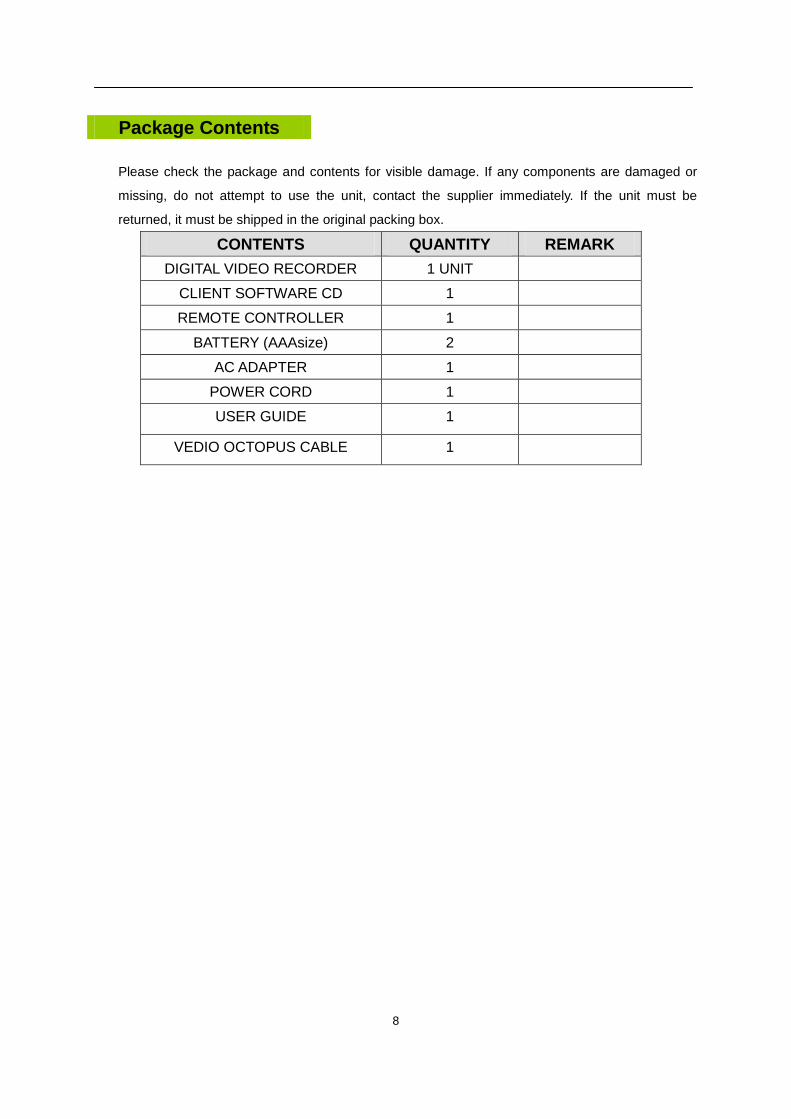
Please check the package and contents for visible damage. If any components are damaged or
missing, do not attempt to use the unit, contact the supplier immediately. If the unit must be
returned, it must be shipped in the original packing box.
CONTENTS QUANTITY REMARK
DIGITAL VIDEO RECORDER 1 UNIT
CLIENT SOFTWARE CD 1
REMOTE CONTROLLER 1
BATTERY (AAAsize) 2
AC ADAPTER 1
POWER CORD 1
USER GUIDE 1
VEDIO OCTOPUS CABLE 1
Package Contents
9
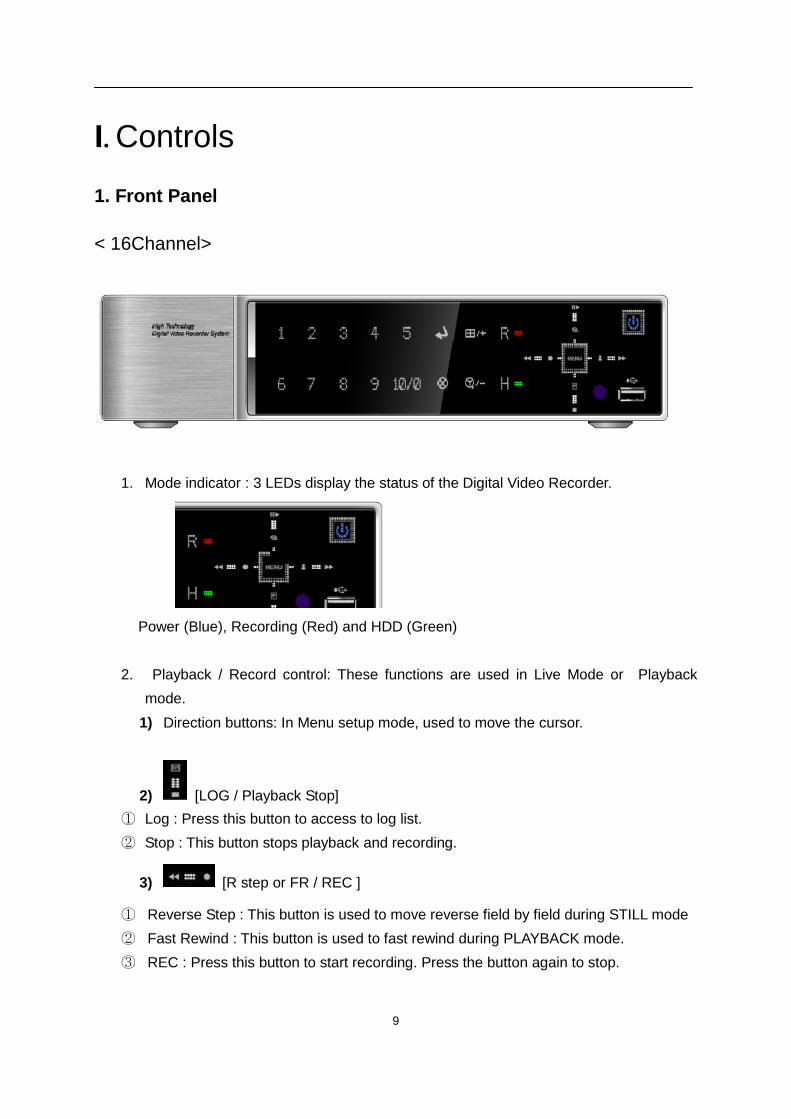
I. Controls
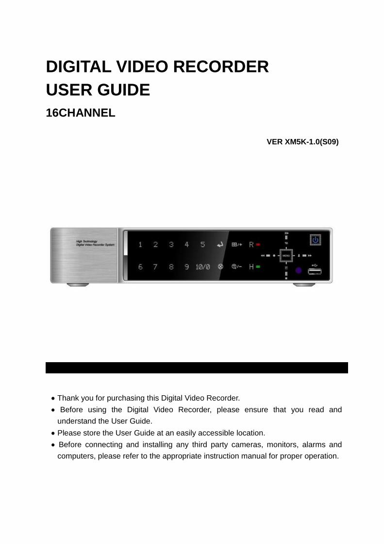
1. Front Panel
< 16Channel>
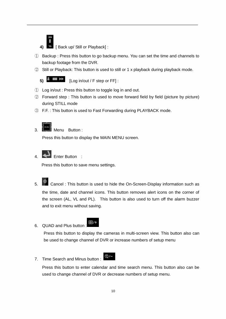
1. Mode indicator : 3 LEDs display the status of the Digital Video Recorder.
Power (Blue), Recording (Red) and HDD (Green)
2. Playback / Record control: These functions are used in Live Mode or Playback
mode.
1) Direction buttons: In Menu setup mode, used to move the cursor.
2) [LOG / Playback Stop]
① Log : Press this button to access to log list.
② Stop : This button stops playback and recording.
3) [R step or FR / REC ]
① Reverse Step : This button is used to move reverse field by field during STILL mode
② Fast Rewind : This button is used to fast rewind during PLAYBACK mode.
③ REC : Press this button to start recording. Press the button again to stop.
10
4) [ Back up/ Still or Playback] :
① Backup : Press this button to go backup menu. You can set the time and channels to
backup footage from the DVR.
② Still or Playback: This button is used to still or 1 x playback during playback mode.
5) [Log in/out / F step or FF] :
① Log in/out : Press this button to toggle log in and out.
② Forward step : This button is used to move forward field by field (picture by picture)
during STILL mode
③ F.F. : This button is used to Fast Forwarding during PLAYBACK mode.
3. Menu Button :
Press this button to display the MAIN MENU screen.
4. Enter Button :
Press this button to save menu settings.
5. Cancel : This button is used to hide the On-Screen-Display information such as
the time, date and channel icons. This button removes alert icons on the corner of
the screen (AL, VL and PL). This button is also used to turn off the alarm buzzer
and to exit menu without saving.
6. QUAD and Plus button :
Press this button to display the cameras in multi-screen view. This button also can
be used to change channel of DVR or increase numbers of setup menu
7. Time Search and Minus button :
Press this button to enter calendar and time search menu. This button also can be
used to change channel of DVR or decrease numbers of setup menu.
11
8. Channel / Numeric Buttons :
Press the buttons to enter data or make selections. Press “–” or “+” to enter
appropriate numbers when prompted for a password, or appropriate dates in
schedule option mode.
[-, +] : To Decrease settings, To Increase settings
Note : This button is used “0” or “10”. Choose channels over 10.
For example, Press this key and “6” to see channel “16”.
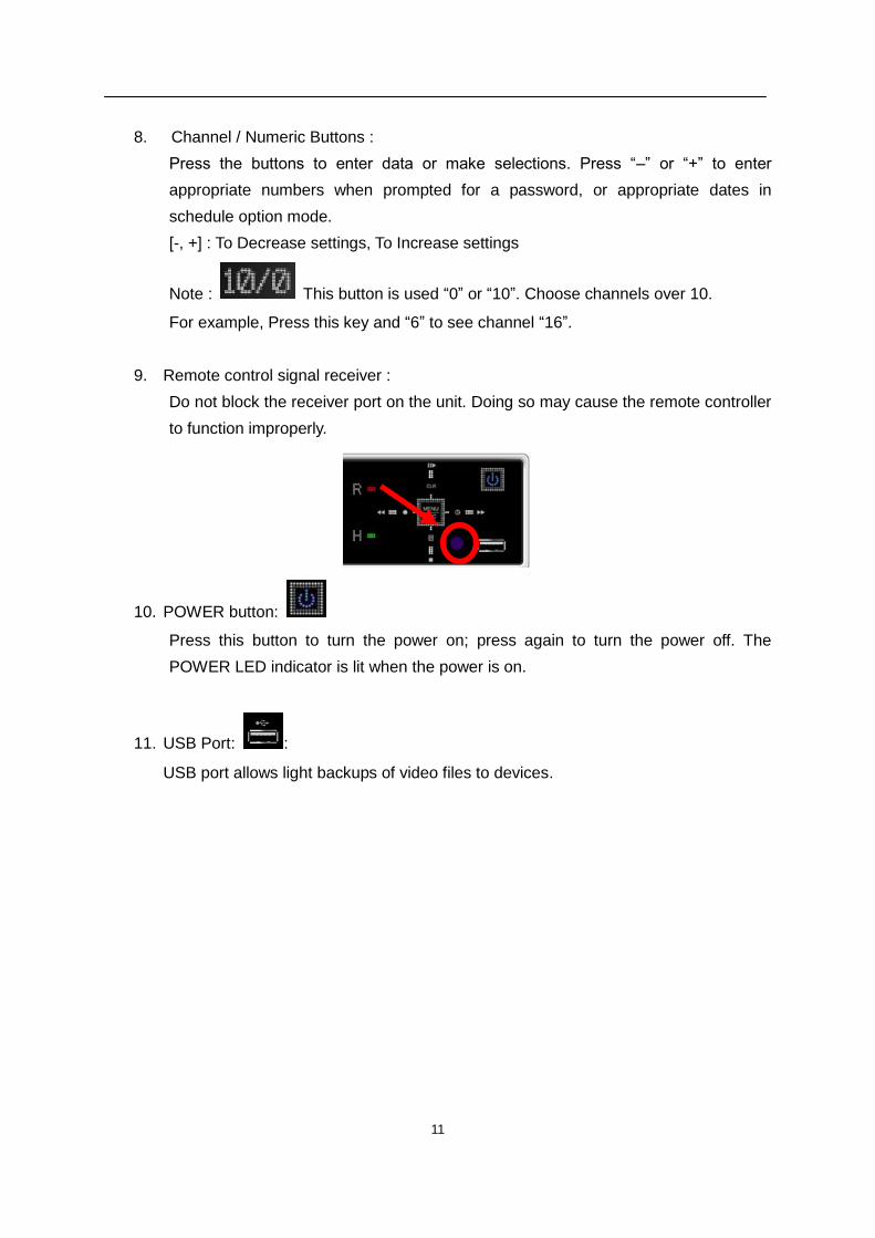
9. Remote control signal receiver :
Do not block the receiver port on the unit. Doing so may cause the remote controller
to function improperly.
10. POWER button:
Press this button to turn the power on; press again to turn the power off. The
POWER LED indicator is lit when the power is on.
11. USB Port: :
USB port allows light backups of video files to devices.
12
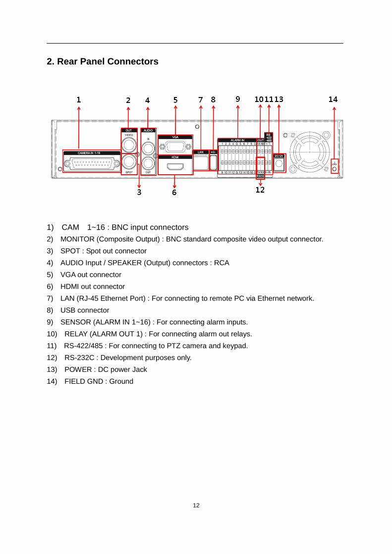
2. Rear Panel Connectors
1) CAM 1~16 : BNC input connectors
2) MONITOR (Composite Output) : BNC standard composite video output connector.
3) SPOT : Spot out connector
4) AUDIO Input / SPEAKER (Output) connectors : RCA
5) VGA out connector
6) HDMI out connector
7) LAN (RJ-45 Ethernet Port) : For connecting to remote PC via Ethernet network.
8) USB connector
9) SENSOR (ALARM IN 1~16) : For connecting alarm inputs.
10) RELAY (ALARM OUT 1) : For connecting alarm out relays.
11) RS-422/485 : For connecting to PTZ camera and keypad.
12) RS-232C : Development purposes only.
13) POWER : DC power Jack
14) FIELD GND : Ground
13
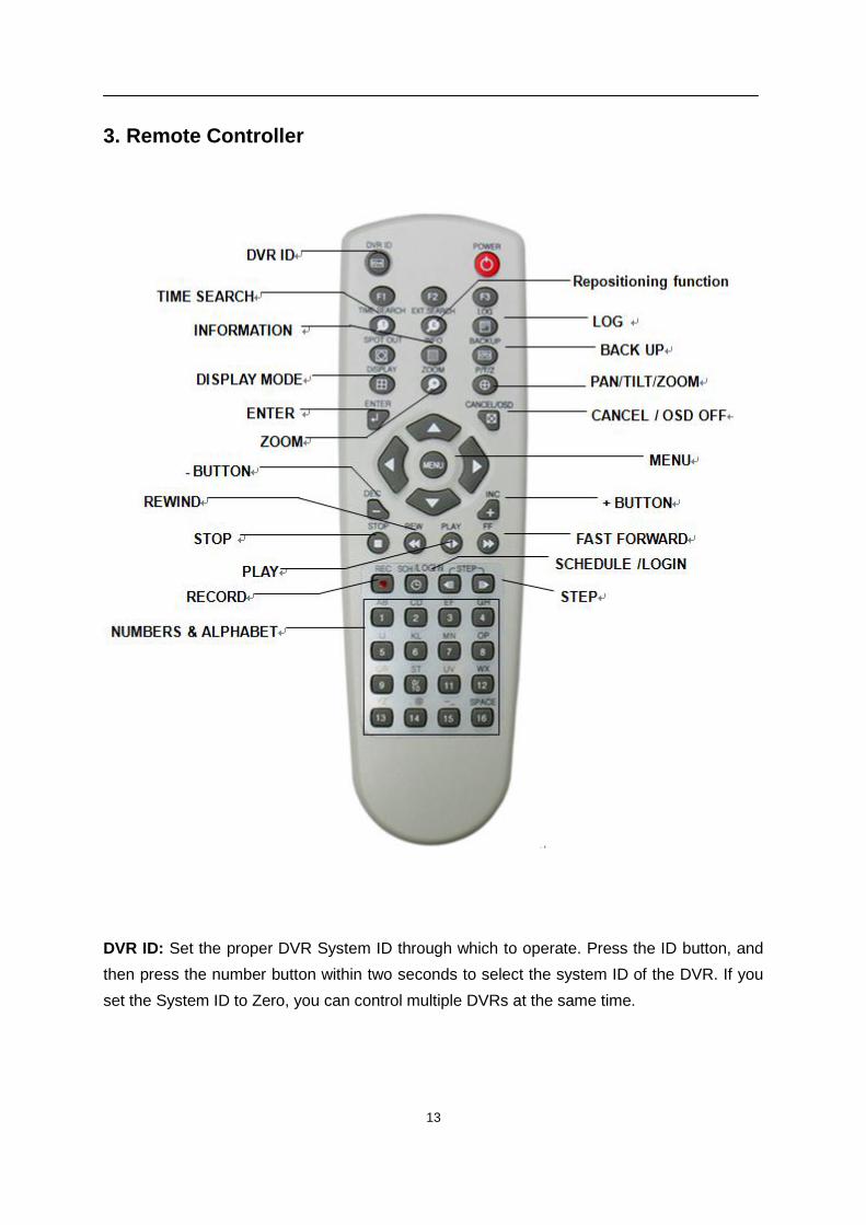
3. Remote Controller
DVR ID: Set the proper DVR System ID through which to operate. Press the ID button, and
then press the number button within two seconds to select the system ID of the DVR. If you
set the System ID to Zero, you can control multiple DVRs at the same time.
14
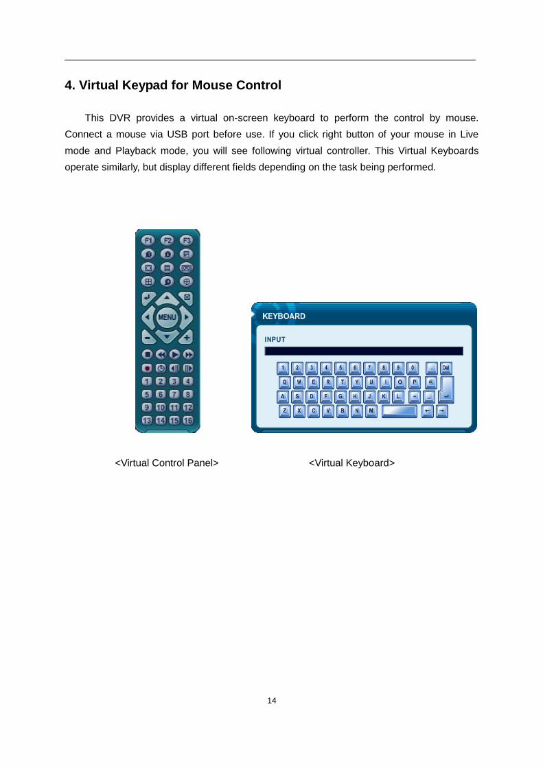
4. Virtual Keypad for Mouse Control
This DVR provides a virtual on-screen keyboard to perform the control by mouse.
Connect a mouse via USB port before use. If you click right button of your mouse in Live
mode and Playback mode, you will see following virtual controller. This Virtual Keyboards
operate similarly, but display different fields depending on the task being performed.
<Virtual Control Panel> <Virtual Keyboard>
15
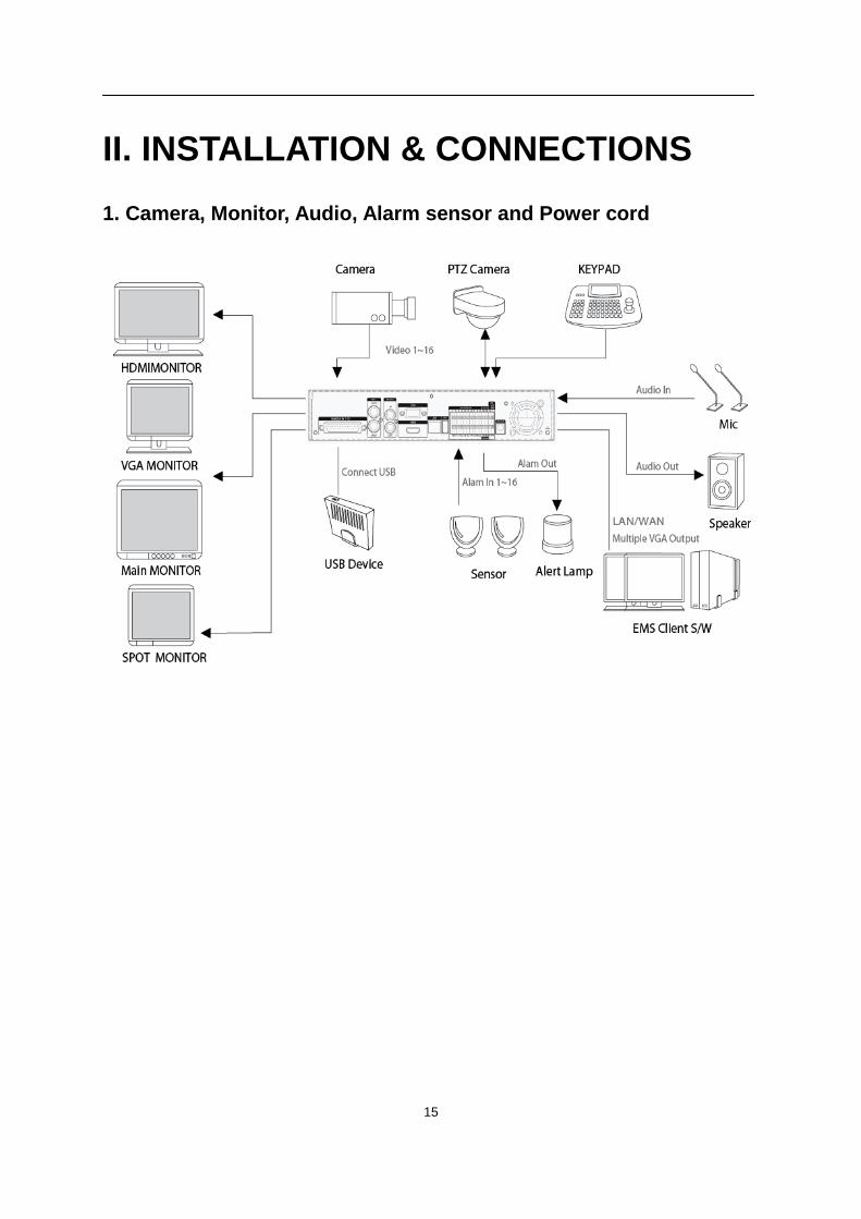
II. INSTALLATION & CONNECTIONS
1. Camera, Monitor, Audio, Alarm sensor and Power cord
16
2. PC system requirement for Network connection.
(a) Pentium-4 2.0GHz or Higher
(b) 512MB RAM
(c) Windows 2000, ME, Windows XP, Window Vista, Window 7
(d) 16MB Video Card
(e) 10/100/1000-BaseT Ethernet Port
(f) CAT-5/6 UTP Cable for LAN
(Crossover cable for direct connect to PC)
<Disclaimer>
The connection and remote viewing of the DVR may not be successful
on all PC’s due to the variety of PC’s internet connection settings.
Please contact the technical support for further assistance.
17
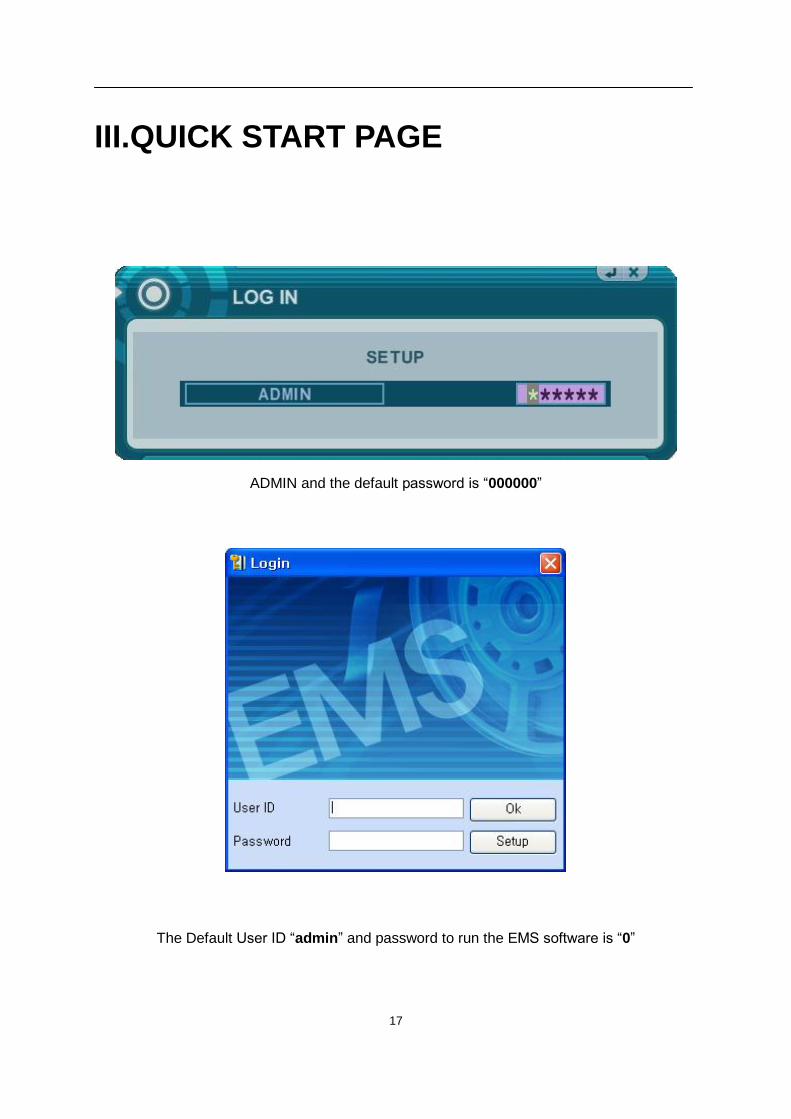
III.QUICK START PAGE
ADMIN and the default password is “000000”
The Default User ID “admin” and password to run the EMS software is “0”
18
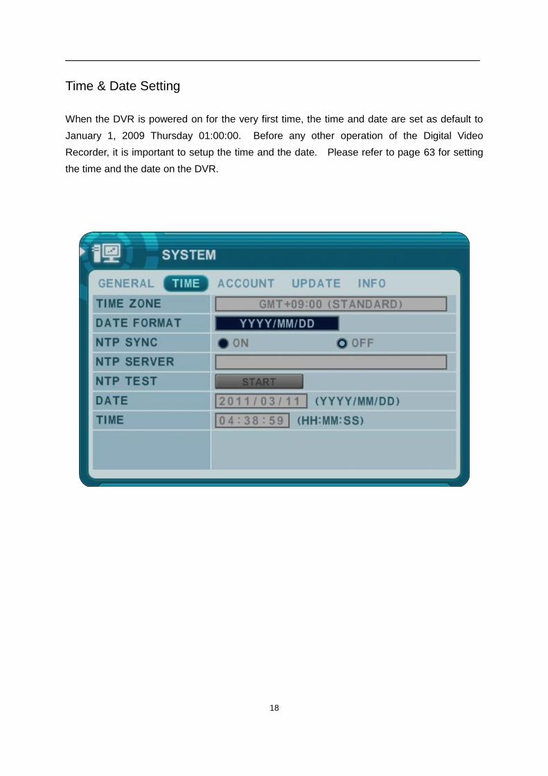
Time & Date Setting
When the DVR is powered on for the very first time, the time and date are set as default to
January 1, 2009 Thursday 01:00:00. Before any other operation of the Digital Video
Recorder, it is important to setup the time and the date. Please refer to page 63 for setting
the time and the date on the DVR.
19
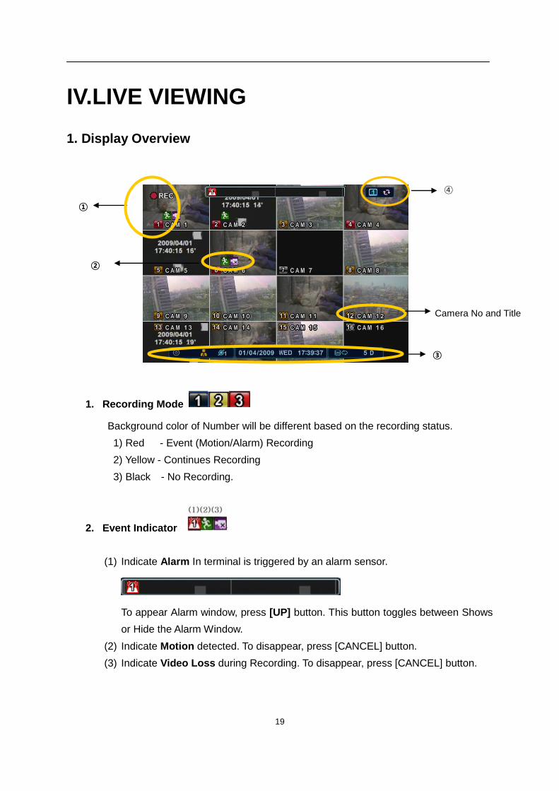
IV.LIVE VIEWING
1. Display Overview
1. Recording Mode
Background color of Number will be different based on the recording status.
1) Red - Event (Motion/Alarm) Recording
2) Yellow - Continues Recording
3) Black - No Recording.
2. Event Indicator
(1) Indicate Alarm In terminal is triggered by an alarm sensor.
To appear Alarm window, press [UP] button. This button toggles between Shows
or Hide the Alarm Window.
(2) Indicate Motion detected. To disappear, press [CANCEL] button.
(3) Indicate Video Loss during Recording. To disappear, press [CANCEL] button.
①
Camera No and Title
④
③
②
20
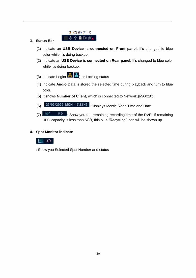
3. Status Bar
(1) Indicate an USB Device is connected on Front panel. It’s changed to blue
color while it’s doing backup.
(2) Indicate an USB Device is connected on Rear panel. It’s changed to blue color
while it’s doing backup.
(3) Indicate Login( ) or Locking status
(4) Indicate Audio Data is stored the selected time during playback and turn to blue
color.
(5) It shows Number of Client, which is connected to Network.(MAX:10)
(6) : Displays Month, Year, Time and Date.
(7) : Show you the remaining recording time of the DVR. If remaining
HDD capacity is less than 5GB, this blue “Recycling” icon will be shown up.
4. Spot Monitor indicate
: Show you Selected Spot Number and status
21
2. Multi-screen Display and Sequencing
2.1. Screen Display.
Select any camera for Full screen display by pressing the Number button of the
desired camera.
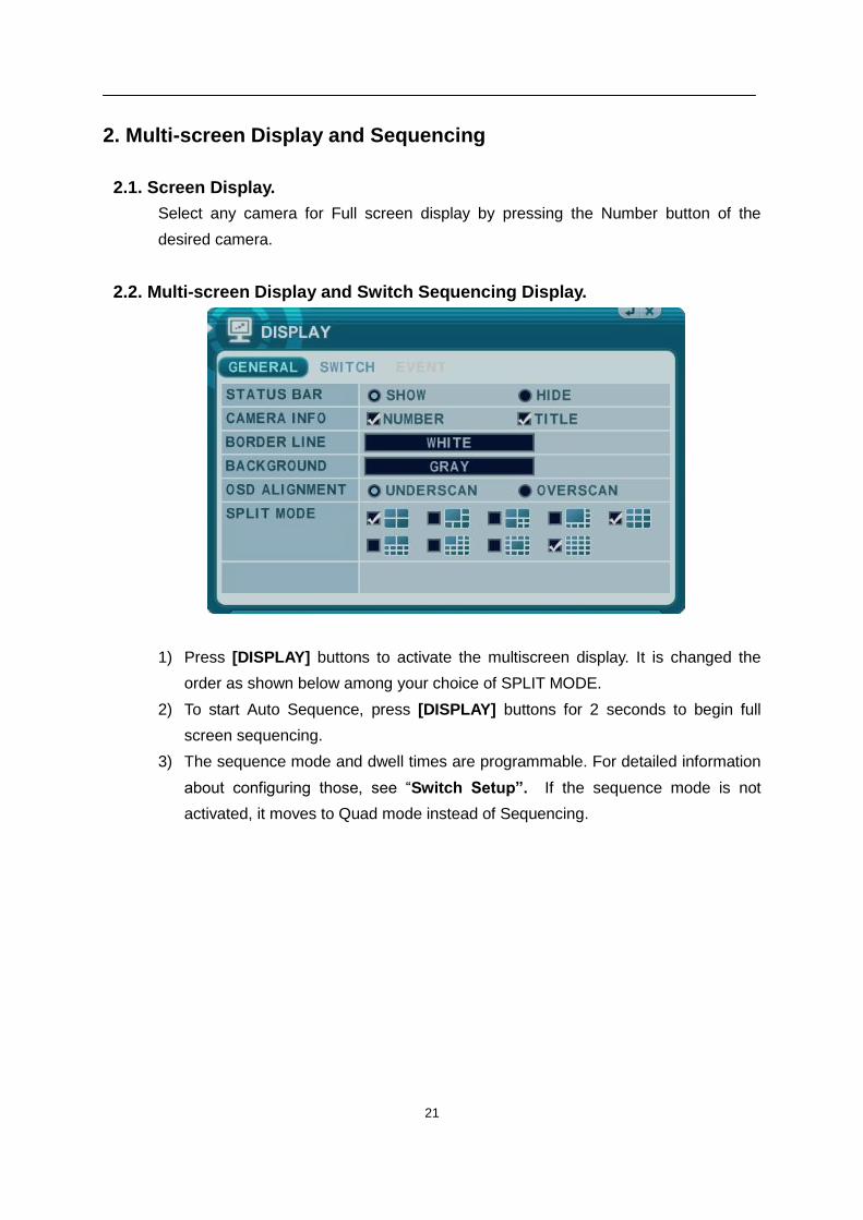
2.2. Multi-screen Display and Switch Sequencing Display.
1) Press [DISPLAY] buttons to activate the multiscreen display. It is changed the
order as shown below among your choice of SPLIT MODE.
2) To start Auto Sequence, press [DISPLAY] buttons for 2 seconds to begin full
screen sequencing.
3) The sequence mode and dwell times are programmable. For detailed information
about configuring those, see “Switch Setup”. If the sequence mode is not
activated, it moves to Quad mode instead of Sequencing.
22
3. Quick button for multi screen Display.
3.1. Quick multi split mode change
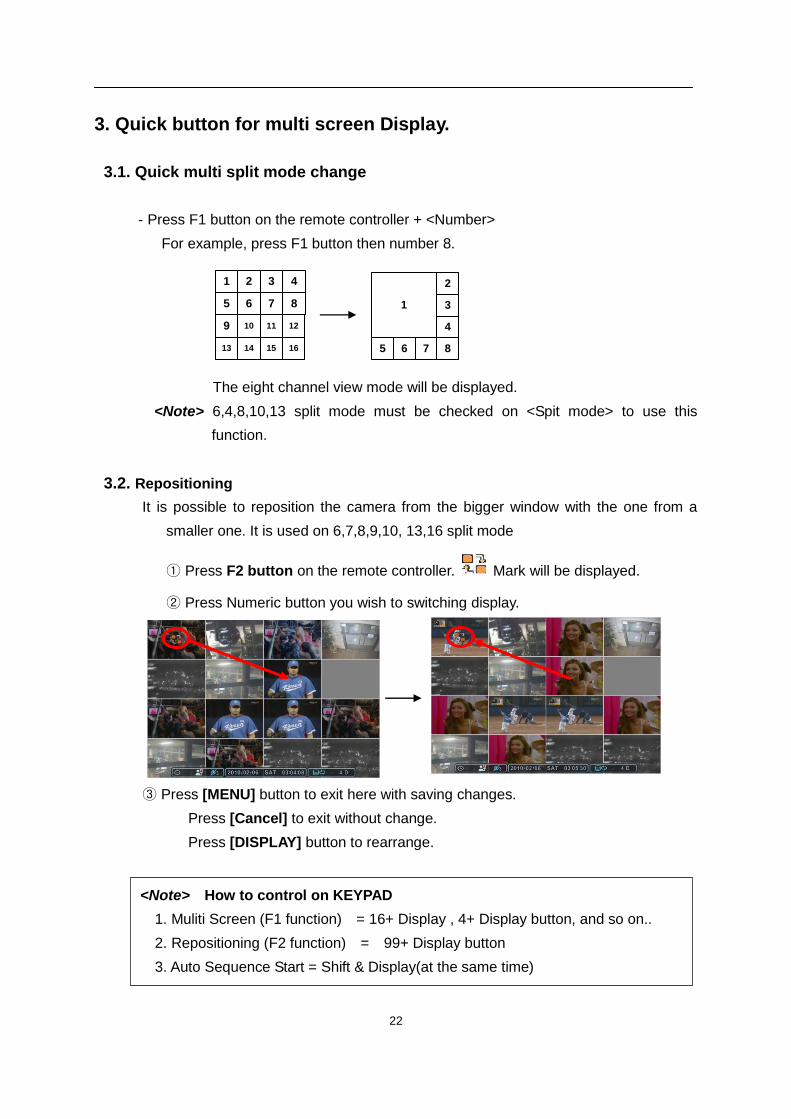
- Press F1 button on the remote controller + <Number>
For example, press F1 button then number 8.
4
8
3
7
2
6
10
1
5
9 11 12
13 14 15 16
2
3
4
8765
1
The eight channel view mode will be displayed.
<Note> 6,4,8,10,13 split mode must be checked on <Spit mode> to use this
function.
3.2. Repositioning
It is possible to reposition the camera from the bigger window with the one from a
smaller one. It is used on 6,7,8,9,10, 13,16 split mode
① Press F2 button on the remote controller. Mark will be displayed.
② Press Numeric button you wish to switching display.
③ Press [MENU] button to exit here with saving changes.
Press [Cancel] to exit without change.
Press [DISPLAY] button to rearrange.
<Note> How to control on KEYPAD
1. Muliti Screen (F1 function) = 16+ Display , 4+ Display button, and so on..
2. Repositioning (F2 function) = 99+ Display button
3. Auto Sequence Start = Shift & Display(at the same time)
23
4. Zooming
During live view mode, it is possible to zoom into a section of the screen to get a close-up
view of the screen.
1. To activate the digital zoom, select the full screen display of the camera you wish to
zoom.
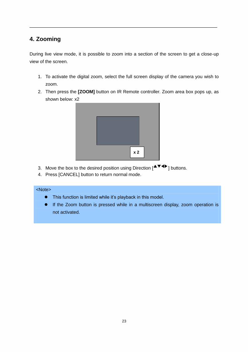
2. Then press the [ZOOM] button on IR Remote controller. Zoom area box pops up, as
shown below: x2
3. Move the box to the desired position using Direction [ ] buttons.
4. Press [CANCEL] button to return normal mode.
<Note>
This function is limited while it’s playback in this model.
If the Zoom button is pressed while in a multiscreen display, zoom operation is
not activated.
x 2
24
5. Spot Monitor
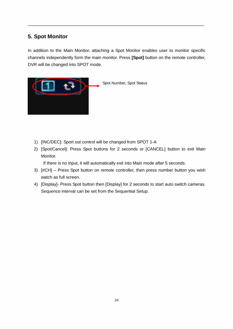
In addition to the Main Monitor, attaching a Spot Monitor enables user to monitor specific
channels independently form the main monitor. Press [Spot] button on the remote controller,
DVR will be changed into SPOT mode.
1) [INC/DEC]: Sport out control will be changed from SPOT 1-A
2) [Spot/Cancel]: Press Spot buttons for 2 seconds or [CANCEL] button to exit Main
Monitor.
If there is no input, it will automatically exit into Main mode after 5 seconds.
3) [#CH] – Press Spot button on remote controller, then press number button you wish
watch as full screen.
4) [Display]- Press Spot button then [Display] for 2 seconds to start auto switch cameras.
Sequence interval can be set from the Sequential Setup.
Spot Number, Spot Status
25
V. OPERATION
1. LOG IN/OUT.
You must log on to the DVR with valid password to operate the DVR. By default, it comes
with one login account; ADMIN and the default password is “000000”.
<Note > If you are logging on for the first time, the system does not prompt you to change
the default password. Therefore, it’s strongly recommended to change the “PASSWORD”
when you install the DVR. Refer to [System Setup].
1. Login
1) On the front panel or remote control, press the power button.
2) When the DVR is powered on, it will start to scan DVR status.
3) Live Viewing screen will appear after initialization about 50sec. It can be delayed
when you have defect HDD, it will try to fix for logical problem but it will show you
warning message for physical problem.
4) On the front panel or remote control, press Login. Using the mouse, click wherever.
the login dialog box pops up.
5) Login Icon will be displayed on status bar.
2. Logout
On the front panel or remote control, press LOGIN. Using the mouse, click wherever
on monitor, Virtual remote control will be appeared. The login icon will be
disappeared on starts bar, indication you are logged off.
26
2. NAVIGATION THE MENU
1. Log on the DVR at admin level or user with configure level.
* User with configure feature is limited to access [DISK and System Menu].
2. On the front panel or remote control, press [MENU]. Using the mouse, click
wherever on monitor, Virtual remote control will be appeared.
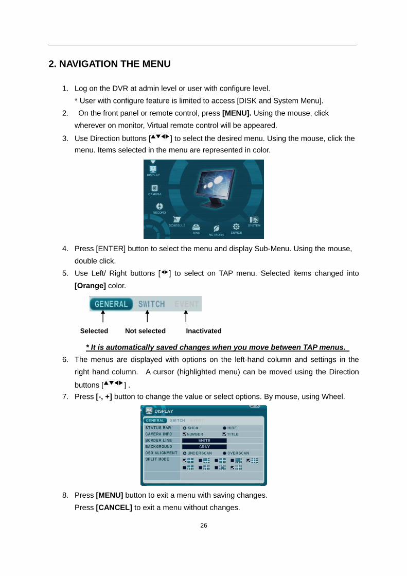
3. Use Direction buttons [ ] to select the desired menu. Using the mouse, click the
menu. Items selected in the menu are represented in color.
4. Press [ENTER] button to select the menu and display Sub-Menu. Using the mouse,
double click.
5. Use Left/ Right buttons [ ] to select on TAP menu. Selected items changed into
[Orange] color.
* It is automatically saved changes when you move between TAP menus.
6. The menus are displayed with options on the left-hand column and settings in the
right hand column. A cursor (highlighted menu) can be moved using the Direction
buttons [ ] .
7. Press [-, +] button to change the value or select options. By mouse, using Wheel.
8. Press [MENU] button to exit a menu with saving changes.
Press [CANCEL] to exit a menu without changes.
Selected Not selected Inactivated
27
VI. SETUP
1. DISPLAY
1.1. GENERAL
1. The menus are displayed with options on the left-hand column and settings in the
right hand column. A cursor (highlighted menu) can be moved using the Direction
buttons [ ] .
2. Change below options using [DEC/INC] buttons.
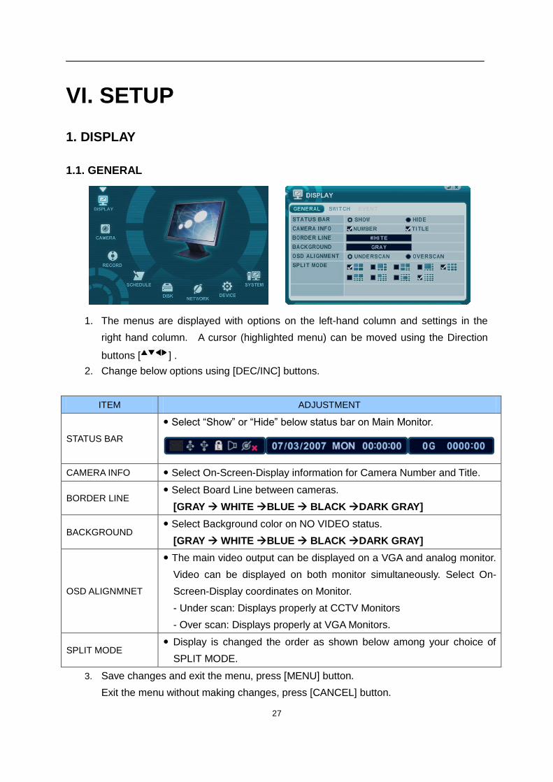
ITEM ADJUSTMENT
STATUS BAR
Select “Show” or “Hide” below status bar on Main Monitor.
CAMERA INFO Select On-Screen-Display information for Camera Number and Title.
BORDER LINE Select Board Line between cameras.
[GRAY WHITE BLUE BLACK DARK GRAY]
BACKGROUND Select Background color on NO VIDEO status.
[GRAY WHITE BLUE BLACK DARK GRAY]
OSD ALIGNMNET
The main video output can be displayed on a VGA and analog monitor.
Video can be displayed on both monitor simultaneously. Select On-
Screen-Display coordinates on Monitor.
- Under scan: Displays properly at CCTV Monitors
- Over scan: Displays properly at VGA Monitors.
SPLIT MODE Display is changed the order as shown below among your choice of
SPLIT MODE.
3. Save changes and exit the menu, press [MENU] button.
Exit the menu without making changes, press [CANCEL] button.
28
1.2. SWITCH Setup (Monitor Configure)
1. The menus are displayed with options on the left-hand column and settings in the right
hand column. A cursor (highlighted menu) can be moved using the Direction buttons
[ ] .
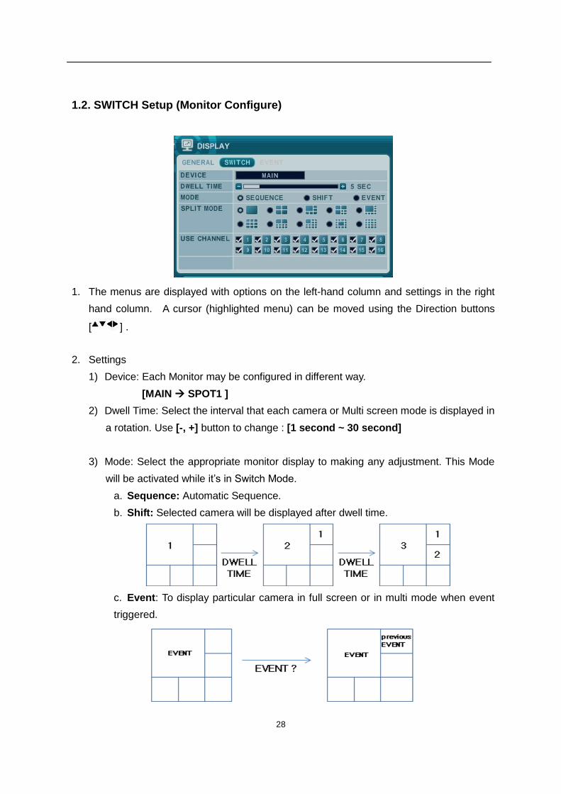
2. Settings
1) Device: Each Monitor may be configured in different way.
[MAIN SPOT1 ]
2) Dwell Time: Select the interval that each camera or Multi screen mode is displayed in
a rotation. Use [-, +] button to change : [1 second ~ 30 second]
3) Mode: Select the appropriate monitor display to making any adjustment. This Mode
will be activated while it’s in Switch Mode.
a. Sequence: Automatic Sequence.
b. Shift: Selected camera will be displayed after dwell time.
c. Event: To display particular camera in full screen or in multi mode when event
triggered.
29
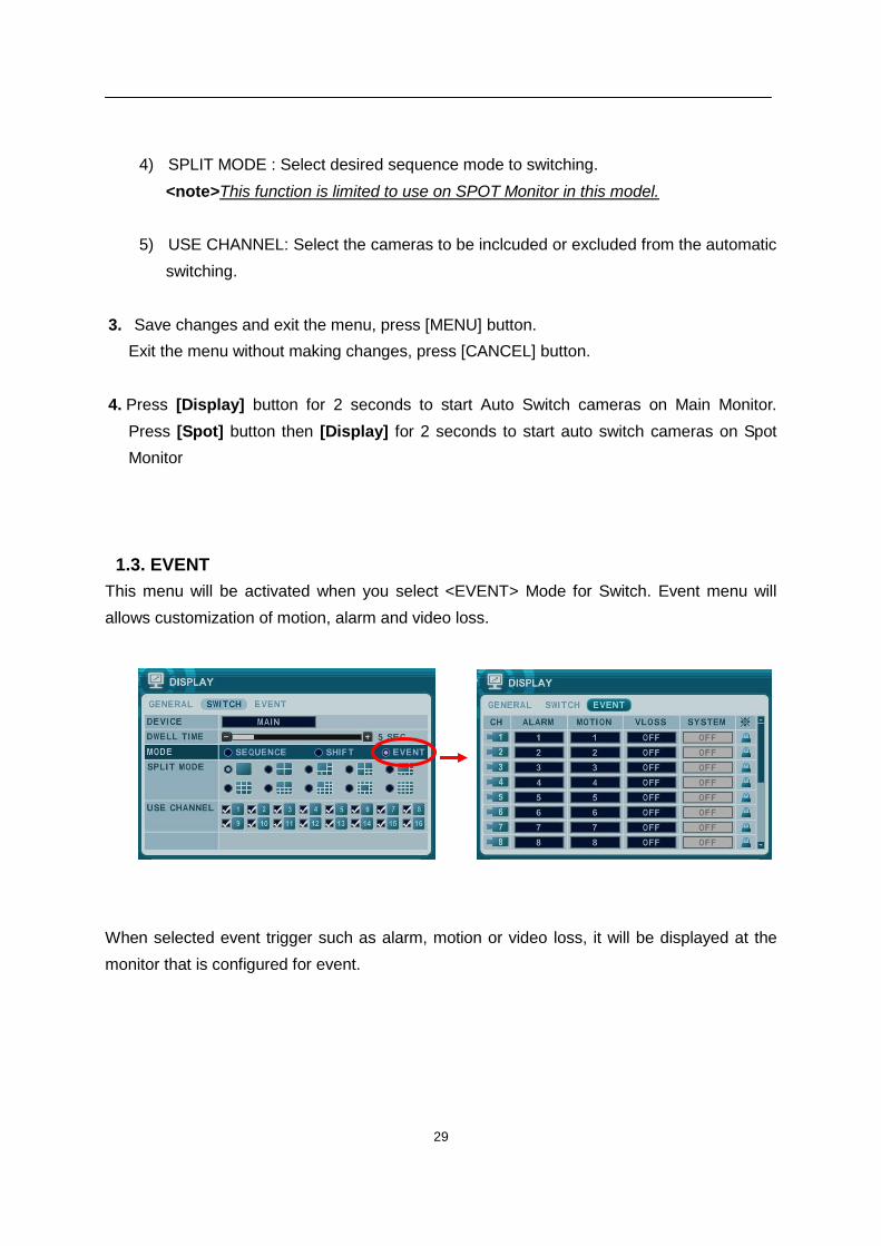
4) SPLIT MODE : Select desired sequence mode to switching.
<note>This function is limited to use on SPOT Monitor in this model.
5) USE CHANNEL: Select the cameras to be inclcuded or excluded from the automatic
switching.
3. Save changes and exit the menu, press [MENU] button.
Exit the menu without making changes, press [CANCEL] button.
4. Press [Display] button for 2 seconds to start Auto Switch cameras on Main Monitor.
Press [Spot] button then [Display] for 2 seconds to start auto switch cameras on Spot
Monitor
1.3. EVENT
This menu will be activated when you select <EVENT> Mode for Switch. Event menu will
allows customization of motion, alarm and video loss.
When selected event trigger such as alarm, motion or video loss, it will be displayed at the
monitor that is configured for event.
30
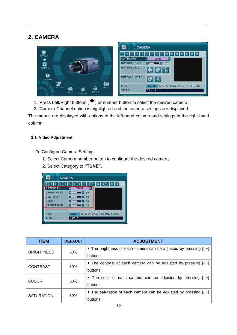
2. CAMERA
1. Press Left/Right buttons [ ] or number button to select the desired camera
2. Camera Channel option is highlighted and the camera settings are displayed.
The menus are displayed with options in the left-hand column and settings in the right hand
column.
2.1. Video Adjustment
To Configure Camera Settings:
1. Select Camera number button to configure the desired camera.
2. Select Category to “TUNE”.
ITEM DEFAULT ADJUSTMENT
BRIGHTNESS 50% The brightness of each camera can be adjusted by pressing [-,+]
buttons.
CONTRAST 50% The contrast of each camera can be adjusted by pressing [-,+]
buttons.
COLOR 50% The color of each camera can be adjusted by pressing [-,+]
buttons.
SATURATION 50% The saturation of each camera can be adjusted by pressing [-,+]
buttons.
31
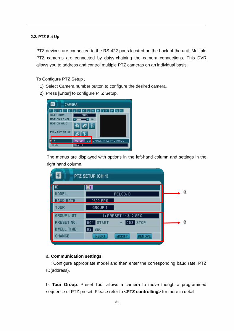
2.2. PTZ Set Up
PTZ devices are connected to the RS-422 ports located on the back of the unit. Multiple
PTZ cameras are connected by daisy-chaining the camera connections. This DVR
allows you to address and control multiple PTZ cameras on an individual basis.
To Configure PTZ Setup ,
1) Select Camera number button to configure the desired camera.
2) Press [Enter] to configure PTZ Setup.
The menus are displayed with options in the left-hand column and settings in the
right hand column.
a. Communication settings.
: Configure appropriate model and then enter the corresponding baud rate, PTZ
ID(address).
b. Tour Group: Preset Tour allows a camera to move though a programmed
sequence of PTZ preset. Please refer to <PTZ controlling> for more in detail.
ⓐ
ⓑ
32
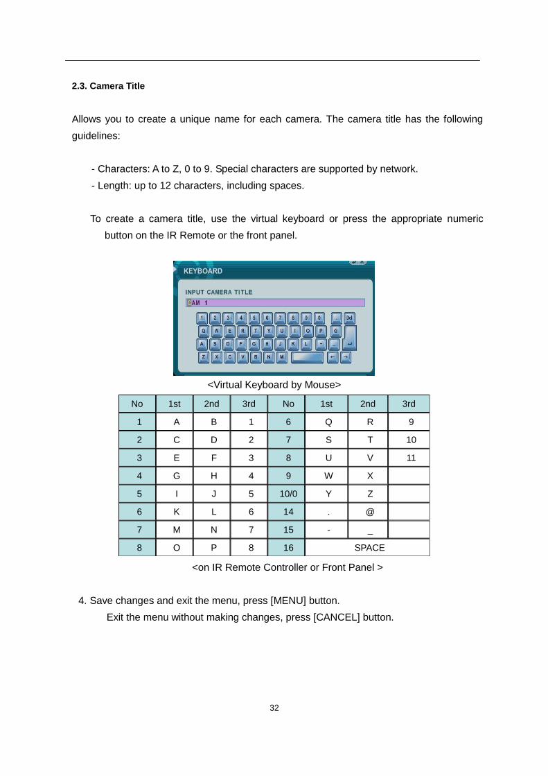
2.3. Camera Title
Allows you to create a unique name for each camera. The camera title has the following
guidelines:
- Characters: A to Z, 0 to 9. Special characters are supported by network.
- Length: up to 12 characters, including spaces.
To create a camera title, use the virtual keyboard or press the appropriate numeric
button on the IR Remote or the front panel.
<Virtual Keyboard by Mouse>
<on IR Remote Controller or Front Panel >
4. Save changes and exit the menu, press [MENU] button.
Exit the menu without making changes, press [CANCEL] button.
No 1st 2nd 3rd No 1st 2nd 3rd
1 A B 1 6 Q R 9
2 C D 2 7 S T 10
3 E F 3 8 U V 11
4 G H 4 9 W X
5 I J 5 10/0 Y Z
6 K L 6 14 . @
7 M N 7 15 - _
8 O P 8 16 SPACE
33
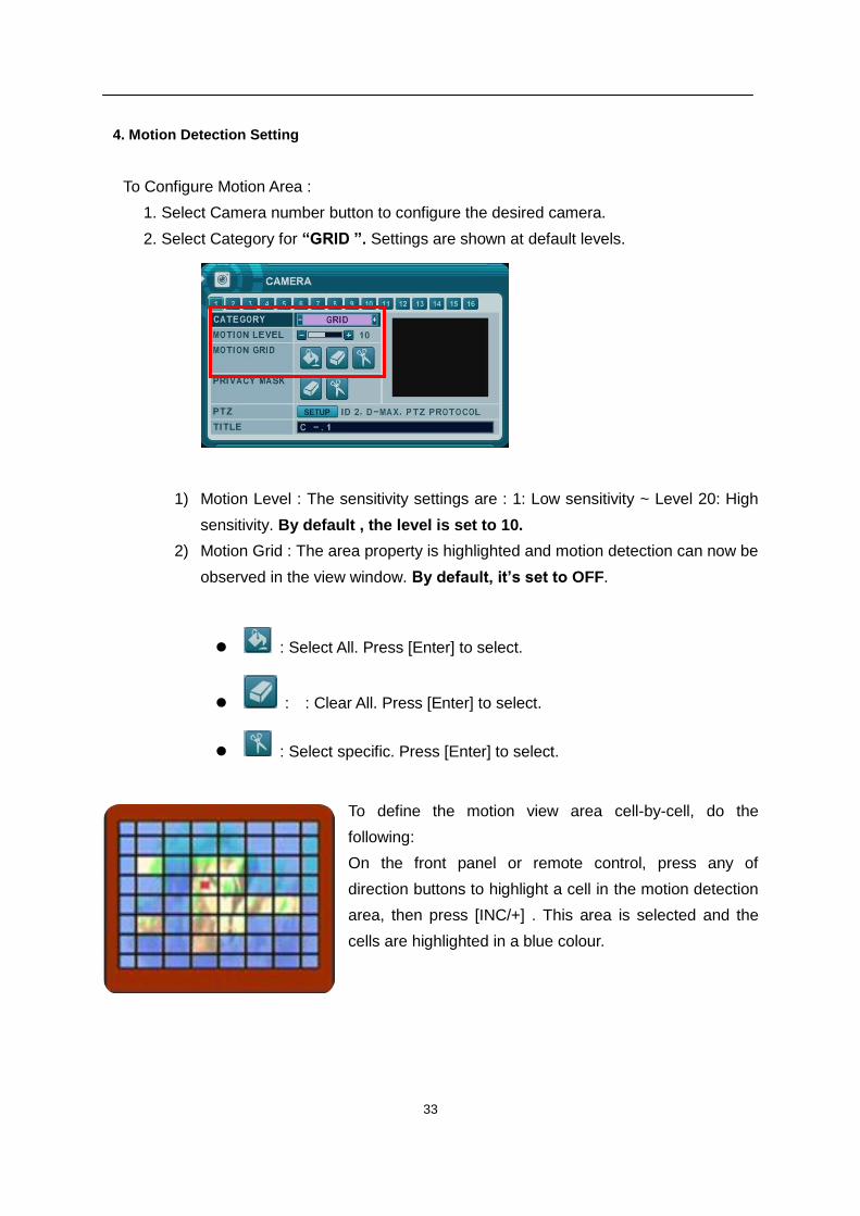
4. Motion Detection Setting
To Configure Motion Area :
1. Select Camera number button to configure the desired camera.
2. Select Category for “GRID ”. Settings are shown at default levels.
1) Motion Level : The sensitivity settings are : 1: Low sensitivity ~ Level 20: High
sensitivity. By default , the level is set to 10.
2) Motion Grid : The area property is highlighted and motion detection can now be
observed in the view window. By default, it’s set to OFF.
: Select All. Press [Enter] to select.
: : Clear All. Press [Enter] to select.
: Select specific. Press [Enter] to select.
To define the motion view area cell-by-cell, do the
following:
On the front panel or remote control, press any of
direction buttons to highlight a cell in the motion detection
area, then press [INC/+] . This area is selected and the
cells are highlighted in a blue colour.
34
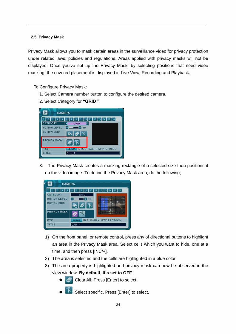
2.5. Privacy Mask
Privacy Mask allows you to mask certain areas in the surveillance video for privacy protection
under related laws, policies and regulations. Areas applied with privacy masks will not be
displayed. Once you’ve set up the Privacy Mask, by selecting positions that need video
masking, the covered placement is displayed in Live View, Recording and Playback.
To Configure Privacy Mask:
1. Select Camera number button to configure the desired camera.
2. Select Category for “GRID ”.
3. The Privacy Mask creates a masking rectangle of a selected size then positions it
on the video image. To define the Privacy Mask area, do the following;
1) On the front panel, or remote control, press any of directional buttons to highlight
an area in the Privacy Mask area. Select cells which you want to hide, one at a
time, and then press [INC/+].
2) The area is selected and the cells are highlighted in a blue color.
3) The area property is highlighted and privacy mask can now be observed in the
view window. By default, it’s set to OFF.
: : Clear All. Press [Enter] to select.
: Select specific. Press [Enter] to select.
35
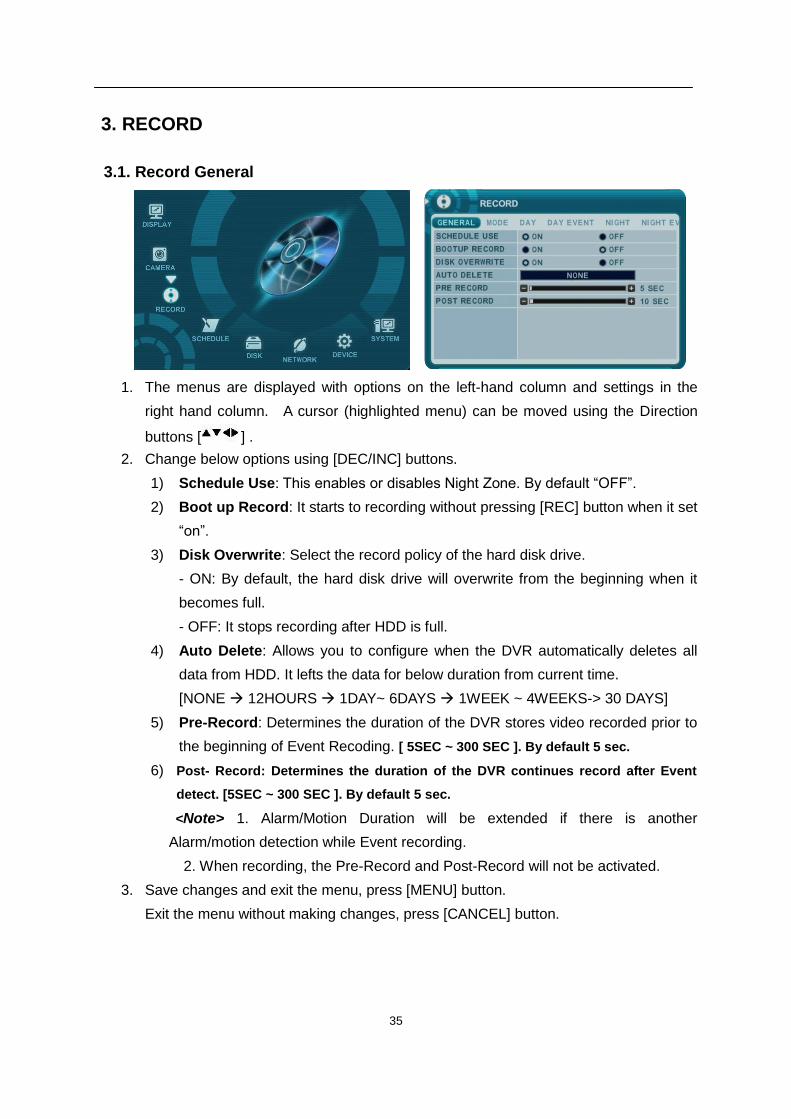
3. RECORD
3.1. Record General
1. The menus are displayed with options on the left-hand column and settings in the
right hand column. A cursor (highlighted menu) can be moved using the Direction
buttons [ ] .
2. Change below options using [DEC/INC] buttons.
1) Schedule Use: This enables or disables Night Zone. By default “OFF”.
2) Boot up Record: It starts to recording without pressing [REC] button when it set
“on”.
3) Disk Overwrite: Select the record policy of the hard disk drive.
- ON: By default, the hard disk drive will overwrite from the beginning when it
becomes full.
- OFF: It stops recording after HDD is full.
4) Auto Delete: Allows you to configure when the DVR automatically deletes all
data from HDD. It lefts the data for below duration from current time.
[NONE 12HOURS 1DAY~ 6DAYS 1WEEK ~ 4WEEKS-> 30 DAYS]
5) Pre-Record: Determines the duration of the DVR stores video recorded prior to
the beginning of Event Recoding. [ 5SEC ~ 300 SEC ]. By default 5 sec.
6) Post- Record: Determines the duration of the DVR continues record after Event
detect. [5SEC ~ 300 SEC ]. By default 5 sec.
<Note> 1. Alarm/Motion Duration will be extended if there is another
Alarm/motion detection while Event recording.
2. When recording, the Pre-Record and Post-Record will not be activated.
3. Save changes and exit the menu, press [MENU] button.
Exit the menu without making changes, press [CANCEL] button.
36
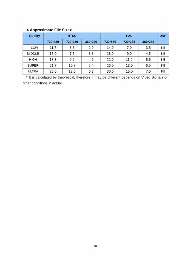
< Approximate File Size>
Quality NTSC PAL UNIT
720*480 720*240 360*240 720*576 720*288 360*288
LOW 11.7 5.8 2.9 14.0 7.0 3.5 KB
MIDDLE 15.0 7.5 3.8 18.0 9.0 4.5 KB
HIGH 18.3 9.2 4.6 22.0 11.0 5.5 KB
SUPER 21.7 10.8 5.4 26.0 13.0 6.5 KB
ULTRA 25.0 12.5 6.3 30.0 15.0 7.5 KB
* It is calculated by theoretical, therefore it may be different depends on Video Signals or
other conditions in actual.
37
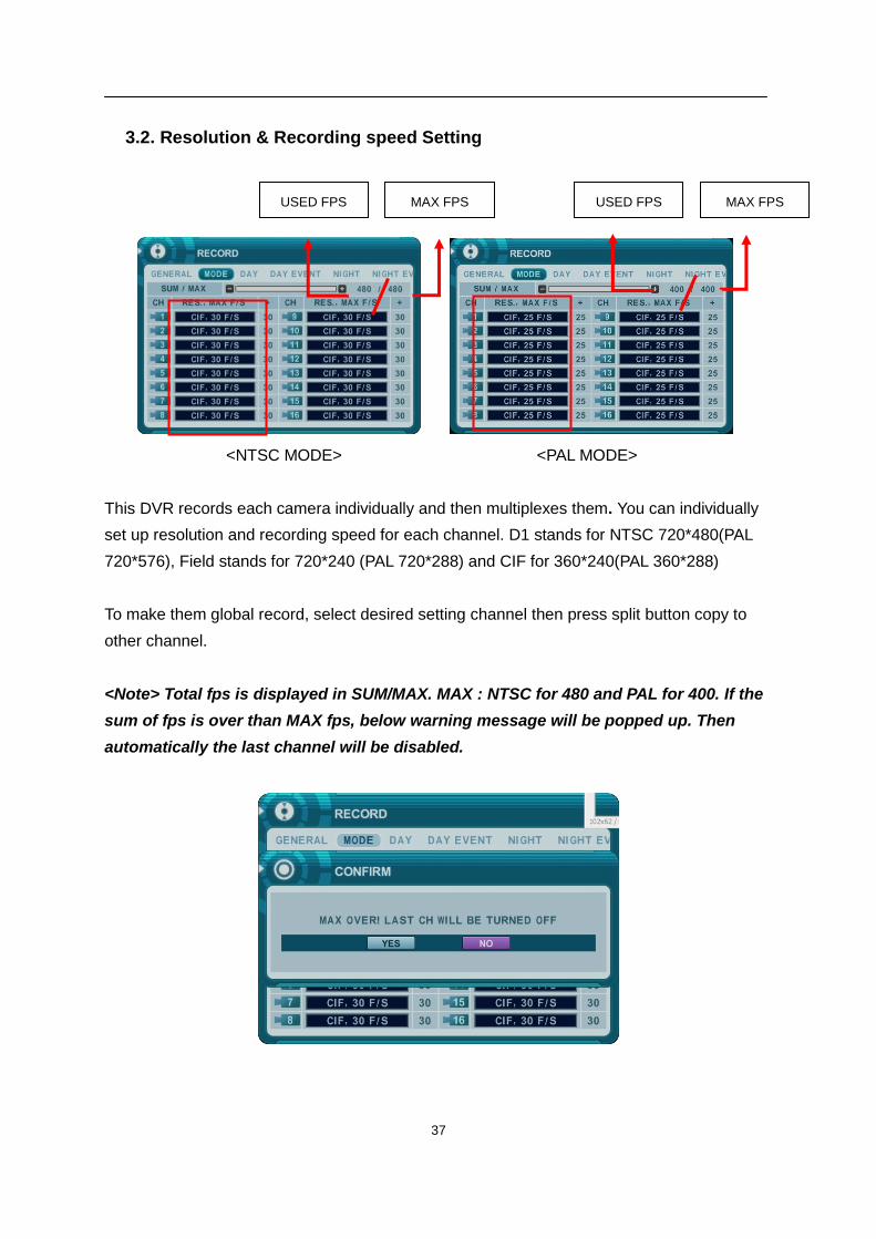
3.2. Resolution & Recording speed Setting
<NTSC MODE> <PAL MODE>
This DVR records each camera individually and then multiplexes them. You can individually
set up resolution and recording speed for each channel. D1 stands for NTSC 720*480(PAL
720*576), Field stands for 720*240 (PAL 720*288) and CIF for 360*240(PAL 360*288)
To make them global record, select desired setting channel then press split button copy to
other channel.
<Note> Total fps is displayed in SUM/MAX. MAX : NTSC for 480 and PAL for 400. If the
sum of fps is over than MAX fps, below warning message will be popped up. Then
automatically the last channel will be disabled.
USED FPS MAX FPS USED FPS
MAX FPS
38
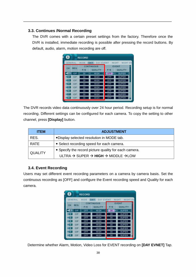
3.3. Continues /Normal Recording
The DVR comes with a certain preset settings from the factory. Therefore once the
DVR is installed, immediate recording is possible after pressing the record buttons. By
default, audio, alarm, motion recording are off.
The DVR records video data continuously over 24 hour period. Recording setup is for normal
recording. Different settings can be configured for each camera. To copy the setting to other
channel, press [Display] button.
ITEM ADJUSTMENT
RES. Display selected resolution in MODE tab.
RATE Select recording speed for each camera.
QUALITY Specify the record picture quality for each camera.
ULTRA SUPER HIGH MIDDLE LOW
3.4. Event Recording
Users may set different event recording parameters on a camera by camera basis. Set the
continuous recording as [OFF] and configure the Event recording speed and Quality for each
camera.
Determine whether Alarm, Motion, Video Loss for EVENT recording on [DAY EVNET] Tap.
39
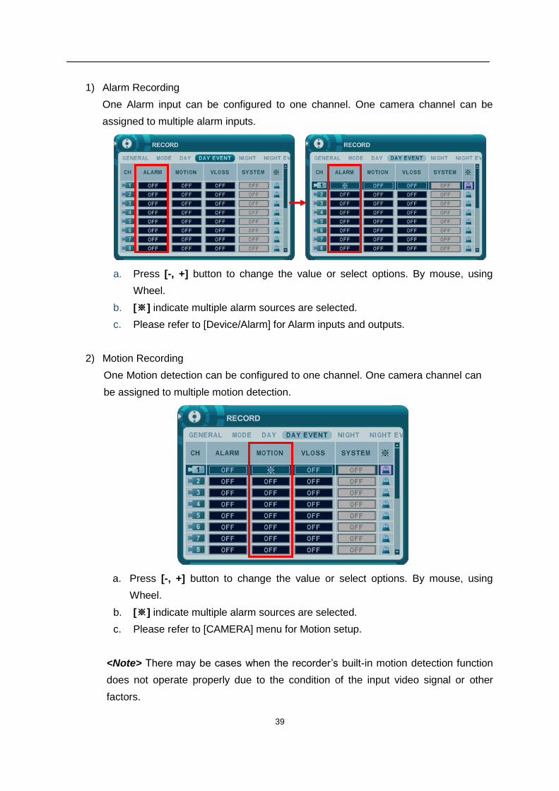
1) Alarm Recording
One Alarm input can be configured to one channel. One camera channel can be
assigned to multiple alarm inputs.
a. Press [-, +] button to change the value or select options. By mouse, using
Wheel.
b. [※] indicate multiple alarm sources are selected.
c. Please refer to [Device/Alarm] for Alarm inputs and outputs.
2) Motion Recording
One Motion detection can be configured to one channel. One camera channel can
be assigned to multiple motion detection.
a. Press [-, +] button to change the value or select options. By mouse, using
Wheel.
b. [※] indicate multiple alarm sources are selected.
c. Please refer to [CAMERA] menu for Motion setup.
<Note> There may be cases when the recorder’s built-in motion detection function
does not operate properly due to the condition of the input video signal or other
factors.
40
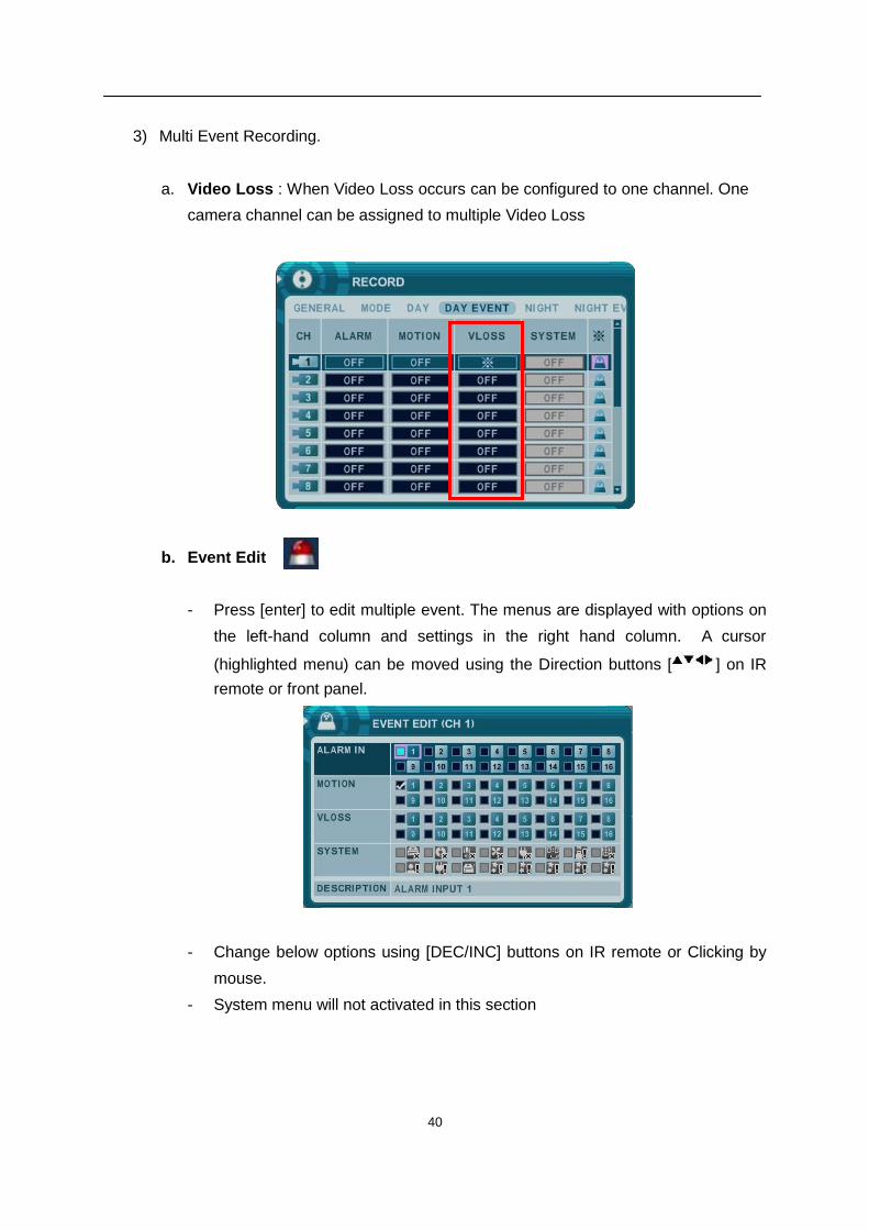
3) Multi Event Recording.
a. Video Loss : When Video Loss occurs can be configured to one channel. One
camera channel can be assigned to multiple Video Loss
b. Event Edit
- Press [enter] to edit multiple event. The menus are displayed with options on
the left-hand column and settings in the right hand column. A cursor
(highlighted menu) can be moved using the Direction buttons [ ] on IR
remote or front panel.
- Change below options using [DEC/INC] buttons on IR remote or Clicking by
mouse.
- System menu will not activated in this section
41
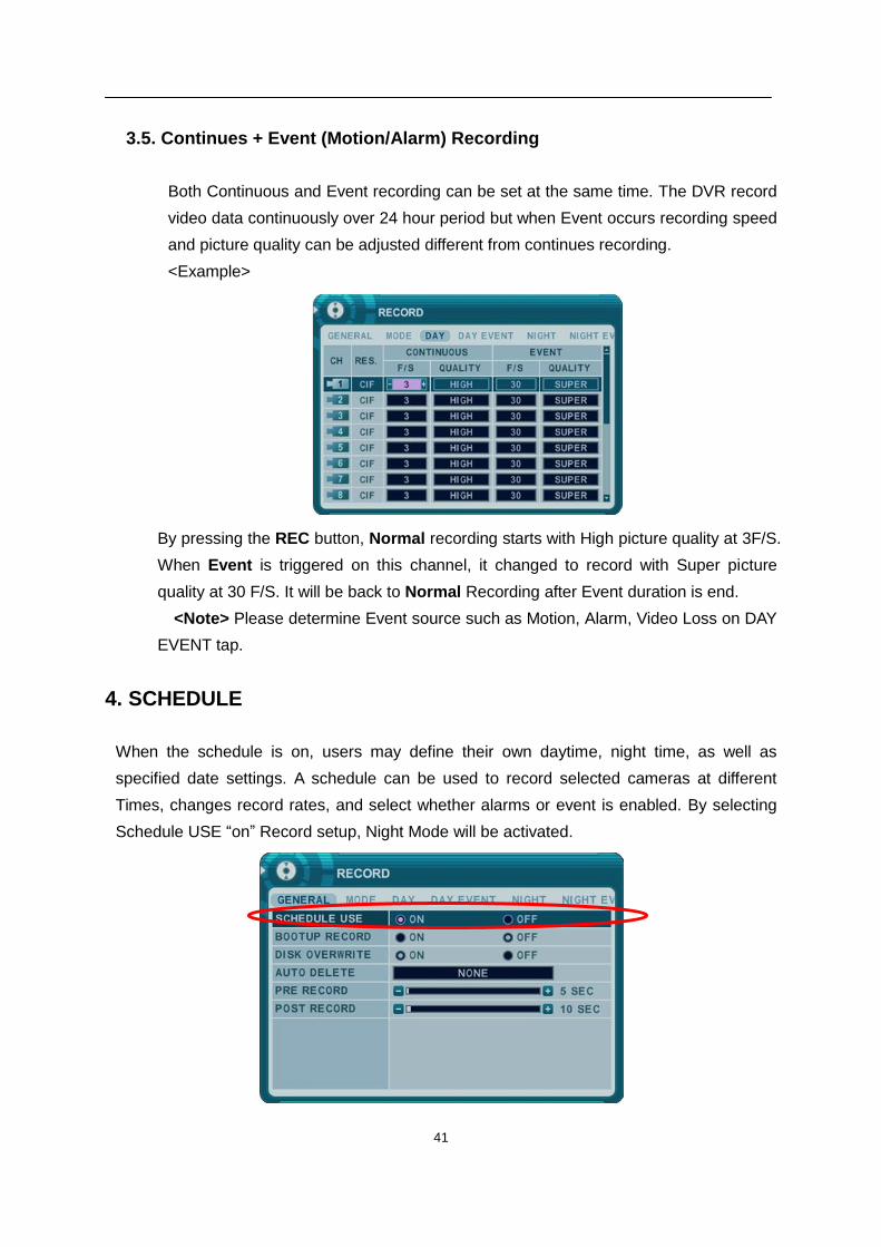
3.5. Continues + Event (Motion/Alarm) Recording
Both Continuous and Event recording can be set at the same time. The DVR record
video data continuously over 24 hour period but when Event occurs recording speed
and picture quality can be adjusted different from continues recording.
<Example>
By pressing the REC button, Normal recording starts with High picture quality at 3F/S.
When Event is triggered on this channel, it changed to record with Super picture
quality at 30 F/S. It will be back to Normal Recording after Event duration is end.
<Note> Please determine Event source such as Motion, Alarm, Video Loss on DAY
EVENT tap.
4. SCHEDULE
When the schedule is on, users may define their own daytime, night time, as well as
specified date settings. A schedule can be used to record selected cameras at different
Times, changes record rates, and select whether alarms or event is enabled. By selecting
Schedule USE “on” Record setup, Night Mode will be activated.
42
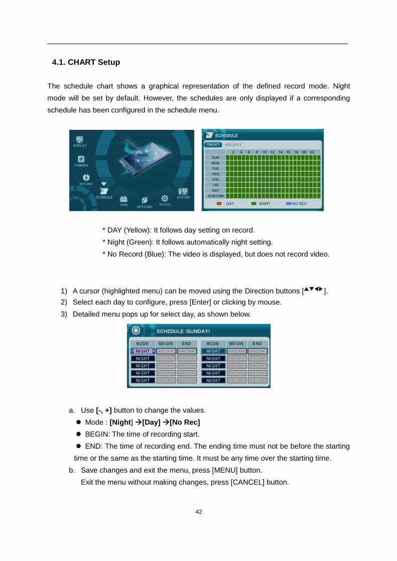
4.1. CHART Setup
The schedule chart shows a graphical representation of the defined record mode. Night
mode will be set by default. However, the schedules are only displayed if a corresponding
schedule has been configured in the schedule menu.
* DAY (Yellow): It follows day setting on record.
* Night (Green): It follows automatically night setting.
* No Record (Blue): The video is displayed, but does not record video.
1) A cursor (highlighted menu) can be moved using the Direction buttons [ ].
2) Select each day to configure, press [Enter] or clicking by mouse.
3) Detailed menu pops up for select day, as shown below.
a. Use [-, +] button to change the values.
Mode : [Night] [Day] [No Rec]
BEGIN: The time of recording start.
END: The time of recording end. The ending time must not be before the starting
time or the same as the starting time. It must be any time over the starting time.
b. Save changes and exit the menu, press [MENU] button.
Exit the menu without making changes, press [CANCEL] button.
43
4) Copying Schedule
a. A cursor (highlighted menu) can be moved using the Direction buttons [ ] on
Day(Sun – Sat)
b. Press [Display] button on desired setting.
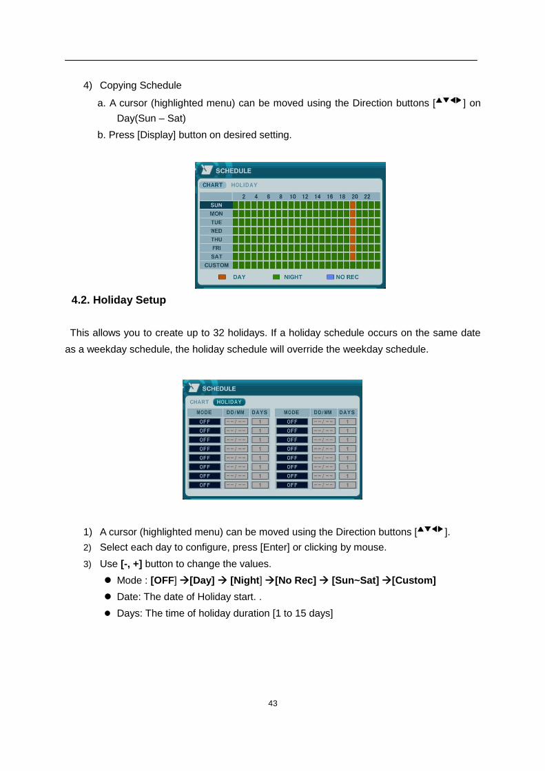
4.2. Holiday Setup
This allows you to create up to 32 holidays. If a holiday schedule occurs on the same date
as a weekday schedule, the holiday schedule will override the weekday schedule.
1) A cursor (highlighted menu) can be moved using the Direction buttons [ ].
2) Select each day to configure, press [Enter] or clicking by mouse.
3) Use [-, +] button to change the values.
Mode : [OFF] [Day] [Night] [No Rec] [Sun~Sat] [Custom]
Date: The date of Holiday start. .
Days: The time of holiday duration [1 to 15 days]
44
5. DISK
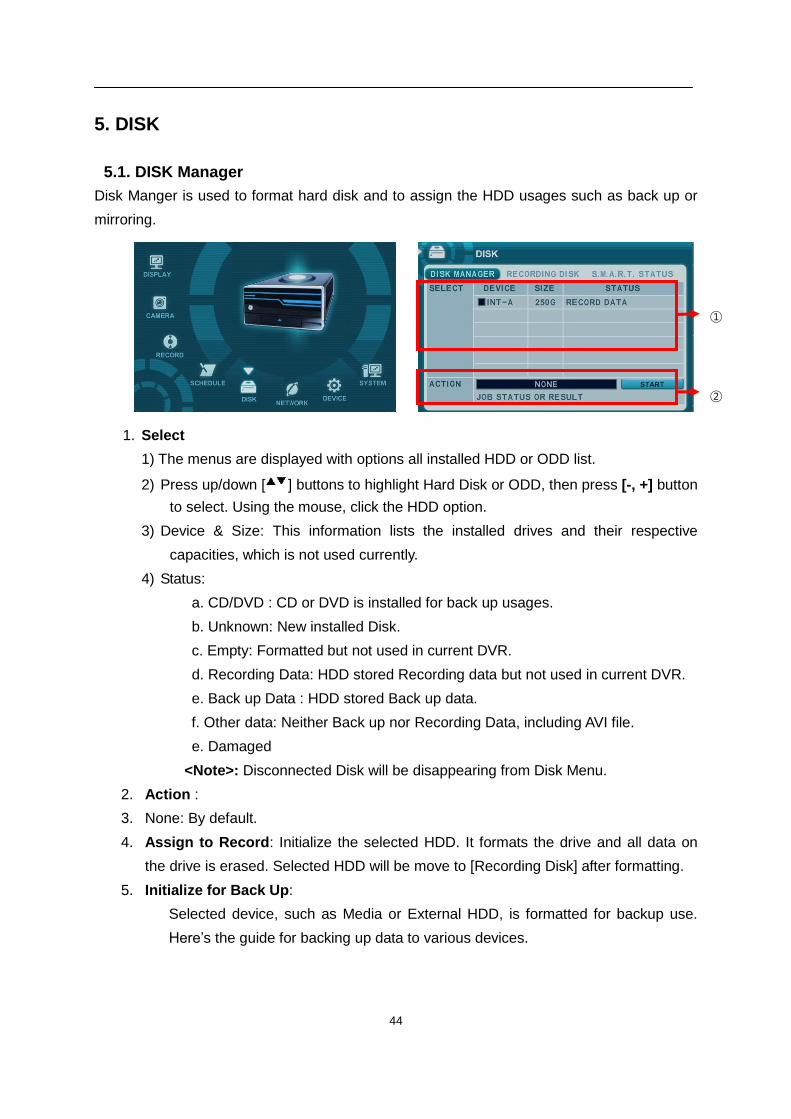
5.1. DISK Manager
Disk Manger is used to format hard disk and to assign the HDD usages such as back up or
mirroring.
1. Select
1) The menus are displayed with options all installed HDD or ODD list.
2) Press up/down [ ] buttons to highlight Hard Disk or ODD, then press [-, +] button
to select. Using the mouse, click the HDD option.
3) Device & Size: This information lists the installed drives and their respective
capacities, which is not used currently.
4) Status:
a. CD/DVD : CD or DVD is installed for back up usages.
b. Unknown: New installed Disk.
c. Empty: Formatted but not used in current DVR.
d. Recording Data: HDD stored Recording data but not used in current DVR.
e. Back up Data : HDD stored Back up data.
f. Other data: Neither Back up nor Recording Data, including AVI file.
e. Damaged
<Note>: Disconnected Disk will be disappearing from Disk Menu.
2. Action :
3. None: By default.
4. Assign to Record: Initialize the selected HDD. It formats the drive and all data on
the drive is erased. Selected HDD will be move to [Recording Disk] after formatting.
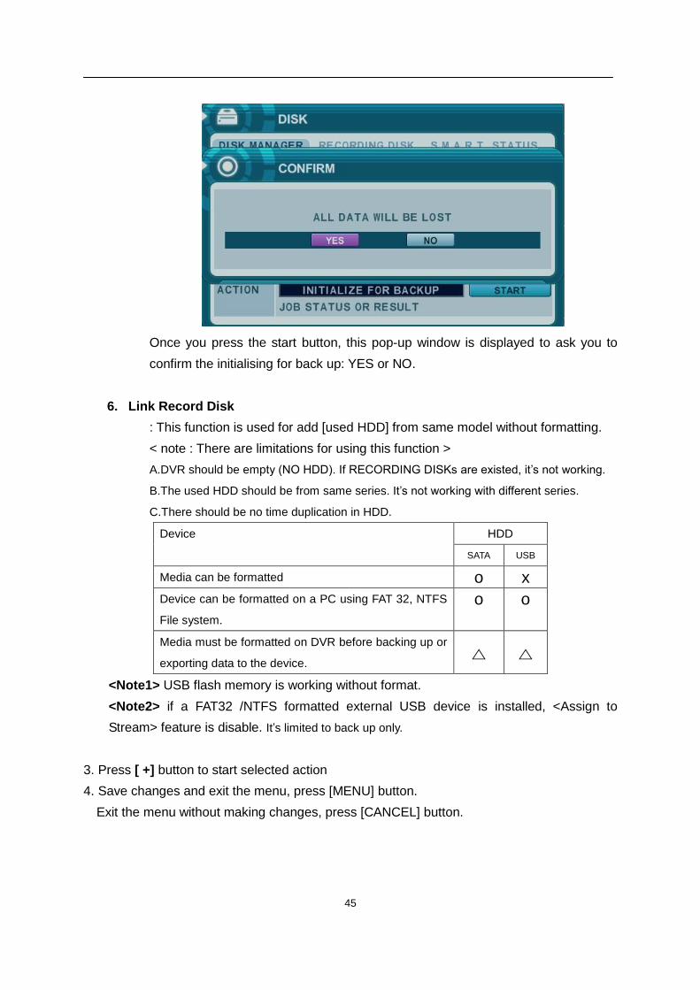
5. Initialize for Back Up:
Selected device, such as Media or External HDD, is formatted for backup use.
Here’s the guide for backing up data to various devices.
①
②
45
Once you press the start button, this pop-up window is displayed to ask you to
confirm the initialising for back up: YES or NO.
6. Link Record Disk
: This function is used for add [used HDD] from same model without formatting.
< note : There are limitations for using this function >
A.DVR should be empty (NO HDD). If RECORDING DISKs are existed, it’s not working.
B.The used HDD should be from same series. It’s not working with different series.
C.There should be no time duplication in HDD.
Device HDD
SATA USB
Media can be formatted o x
Device can be formatted on a PC using FAT 32, NTFS
File system.
o o
Media must be formatted on DVR before backing up or
exporting data to the device. △ △
<Note1> USB flash memory is working without format.
<Note2> if a FAT32 /NTFS formatted external USB device is installed, <Assign to
Stream> feature is disable. It’s limited to back up only.
3. Press [ +] button to start selected action
4. Save changes and exit the menu, press [MENU] button.
Exit the menu without making changes, press [CANCEL] button.
46
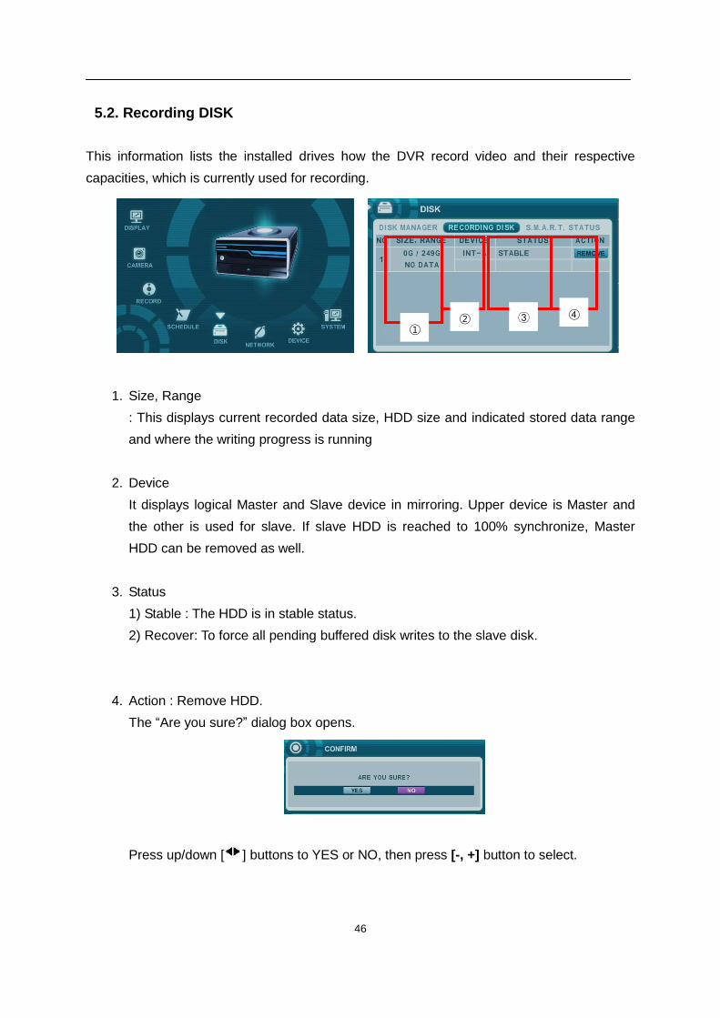
5.2. Recording DISK
This information lists the installed drives how the DVR record video and their respective
capacities, which is currently used for recording.
1. Size, Range
: This displays current recorded data size, HDD size and indicated stored data range
and where the writing progress is running
2. Device
It displays logical Master and Slave device in mirroring. Upper device is Master and
the other is used for slave. If slave HDD is reached to 100% synchronize, Master
HDD can be removed as well.
3. Status
1) Stable : The HDD is in stable status.
2) Recover: To force all pending buffered disk writes to the slave disk.
4. Action : Remove HDD.
The “Are you sure?” dialog box opens.
Press up/down [ ] buttons to YES or NO, then press [-, +] button to select.
① ② ③ ④
47
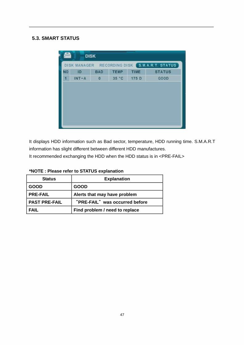
5.3. SMART STATUS
It displays HDD information such as Bad sector, temperature, HDD running time. S.M.A.R.T
information has slight different between different HDD manufactures.
It recommended exchanging the HDD when the HDD status is in <PRE-FAIL>
*NOTE : Please refer to STATUS explanation
Status Explanation
GOOD GOOD
PRE-FAIL Alerts that may have problem
PAST PRE-FAIL “PRE-FAIL”was occurred before
FAIL Find problem / need to replace
48
6. NETWORK
The static service consists of an IP address that remains constant for the duration of the
contract of the internet service, whereas the dynamic service consists of an IP address that
frequently changes every time a new connection is made through the provided modem, or
recurrently in a given period of time. Though most internet service providers offer both
solutions, this manual will distinguish the two solutions according to the commonly available
service type to configure the DVR for the networking purposes.
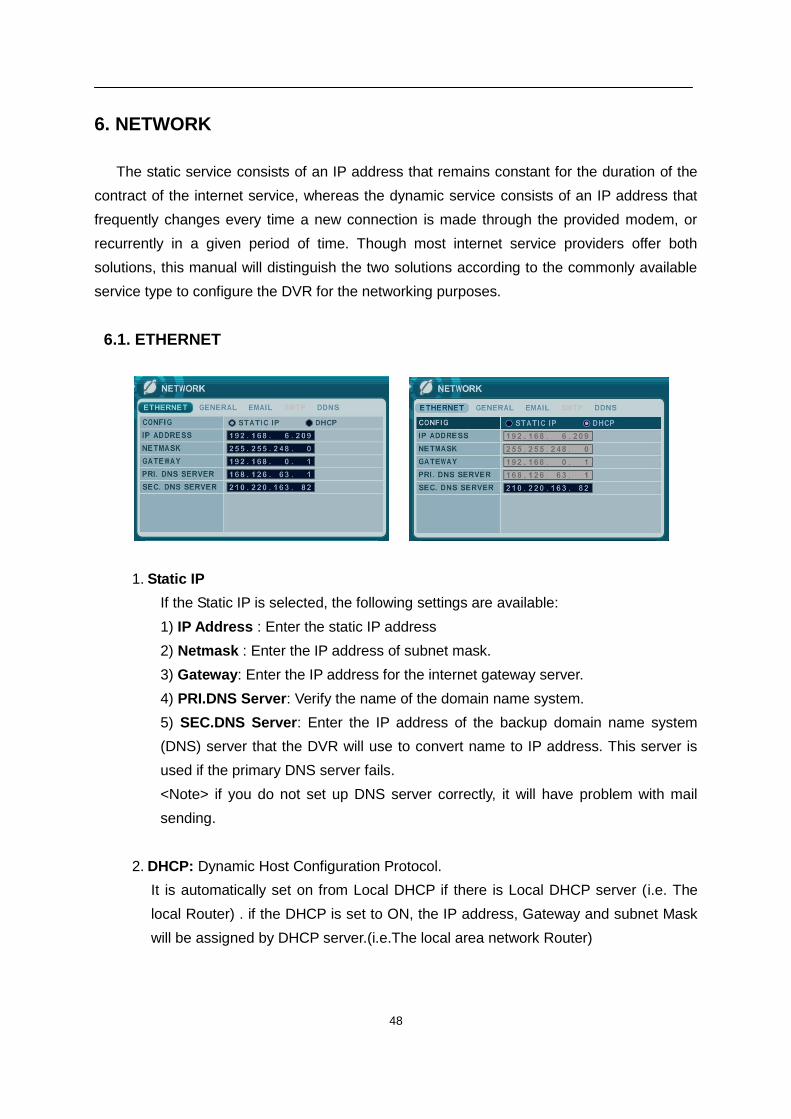
6.1. ETHERNET
1. Static IP
If the Static IP is selected, the following settings are available:
1) IP Address : Enter the static IP address
2) Netmask : Enter the IP address of subnet mask.
3) Gateway: Enter the IP address for the internet gateway server.
4) PRI.DNS Server: Verify the name of the domain name system.
5) SEC.DNS Server: Enter the IP address of the backup domain name system
(DNS) server that the DVR will use to convert name to IP address. This server is
used if the primary DNS server fails.
<Note> if you do not set up DNS server correctly, it will have problem with mail
sending.
2. DHCP: Dynamic Host Configuration Protocol.
It is automatically set on from Local DHCP if there is Local DHCP server (i.e. The
local Router) . if the DHCP is set to ON, the IP address, Gateway and subnet Mask
will be assigned by DHCP server.(i.e.The local area network Router)
49
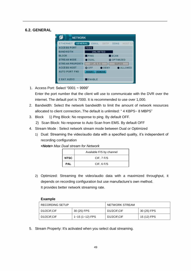
6.2. GENERAL
1. Access Port: Select “0001 ~ 9999”
Enter the port number that the client will use to communicate with the DVR over the
internet. The default port is 7000. It is recommended to use over 1,000.
2. Bandwidth: Select the network bandwidth to limit the amount of network resources
allocated to client connection..The default is unlimited: “ 4 KBPS~ 8 MBPS”
3. Block 1) Ping Block: No response to ping. By default OFF.
2) Scan Block: No response to Auto Scan from EMS. By default OFF
4. Stream Mode : Select network stream mode between Dual or Optimized
1) Dual: Streaming the video/audio data with a specified quality, it’s independent of
recording configuration
<Note> Max Dual stream for Network
Available F/S by channel
NTSC CIF, 7 F/S
PAL CIF, 6 F/S
2) Optimized: Streaming the video/audio data with a maximized throughput, it
depends on recording configuration but use manufacture’s own method.
It provides better network streaming rate.
Example
RECORDING SETUP NETWORK STREAM
D1/2CIF,CIF 30 (25) FPS D1/2CIF,CIF 30 (25) FPS
D1/2CIF,CIF 1~15 (1~12) FPS D1/2CIF,CIF 15 (12) FPS
5. Stream Property: It’s activated when you select dual streaming.
50
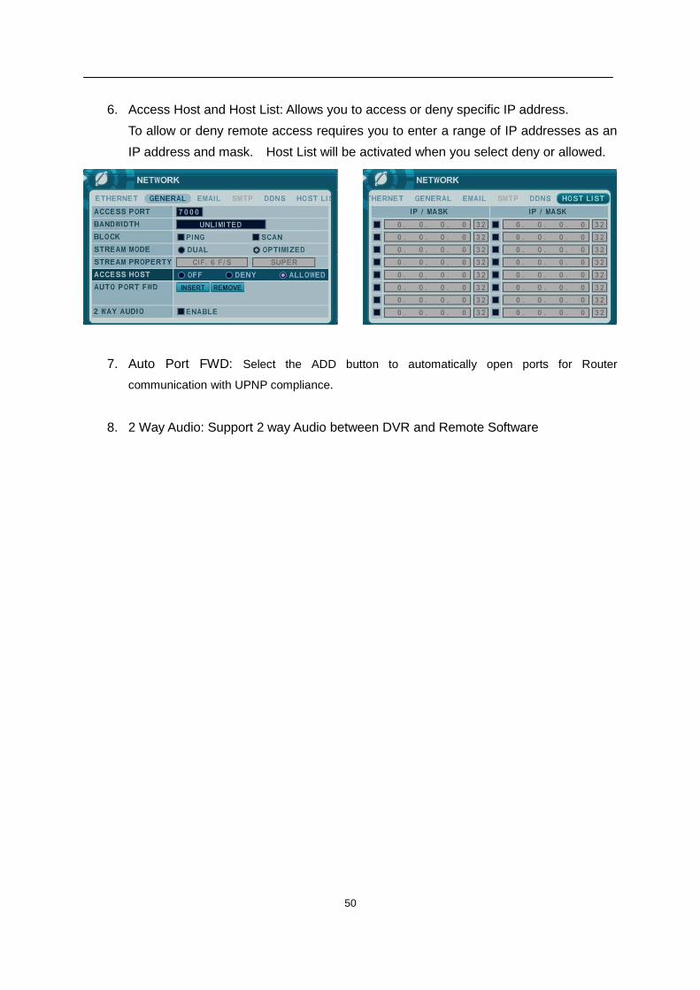
6. Access Host and Host List: Allows you to access or deny specific IP address.
To allow or deny remote access requires you to enter a range of IP addresses as an
IP address and mask. Host List will be activated when you select deny or allowed.
7. Auto Port FWD: Select the ADD button to automatically open ports for Router
communication with UPNP compliance.
8. 2 Way Audio: Support 2 way Audio between DVR and Remote Software
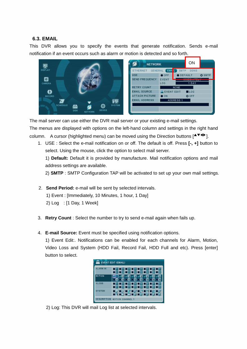
6.3. EMAIL
This DVR allows you to specify the events that generate notification. Sends e-mail
notification if an event occurs such as alarm or motion is detected and so forth.
The mail server can use either the DVR mail server or your existing e-mail settings.
The menus are displayed with options on the left-hand column and settings in the right hand
column. A cursor (highlighted menu) can be moved using the Direction buttons [ ].
1. USE : Select the e-mail notification on or off. The default is off. Press [-, +] button to
select. Using the mouse, click the option to select mail server.
1) Default: Default it is provided by manufacture. Mail notification options and mail
address settings are available.
2) SMTP : SMTP Configuration TAP will be activated to set up your own mail settings.
2. Send Period: e-mail will be sent by selected intervals.
1) Event : [Immediately, 10 Minutes, 1 hour, 1 Day]
2) Log : [1 Day, 1 Week]
3. Retry Count : Select the number to try to send e-mail again when fails up.
4. E-mail Source: Event must be specified using notification options.
1) Event Edit:. Notifications can be enabled for each channels for Alarm, Motion,
Video Loss and System (HDD Fail, Record Fail, HDD Full and etc). Press [enter]
button to select.
2) Log: This DVR will mail Log list at selected intervals.
ON
1 DIGITAL VIDEO RECORDER
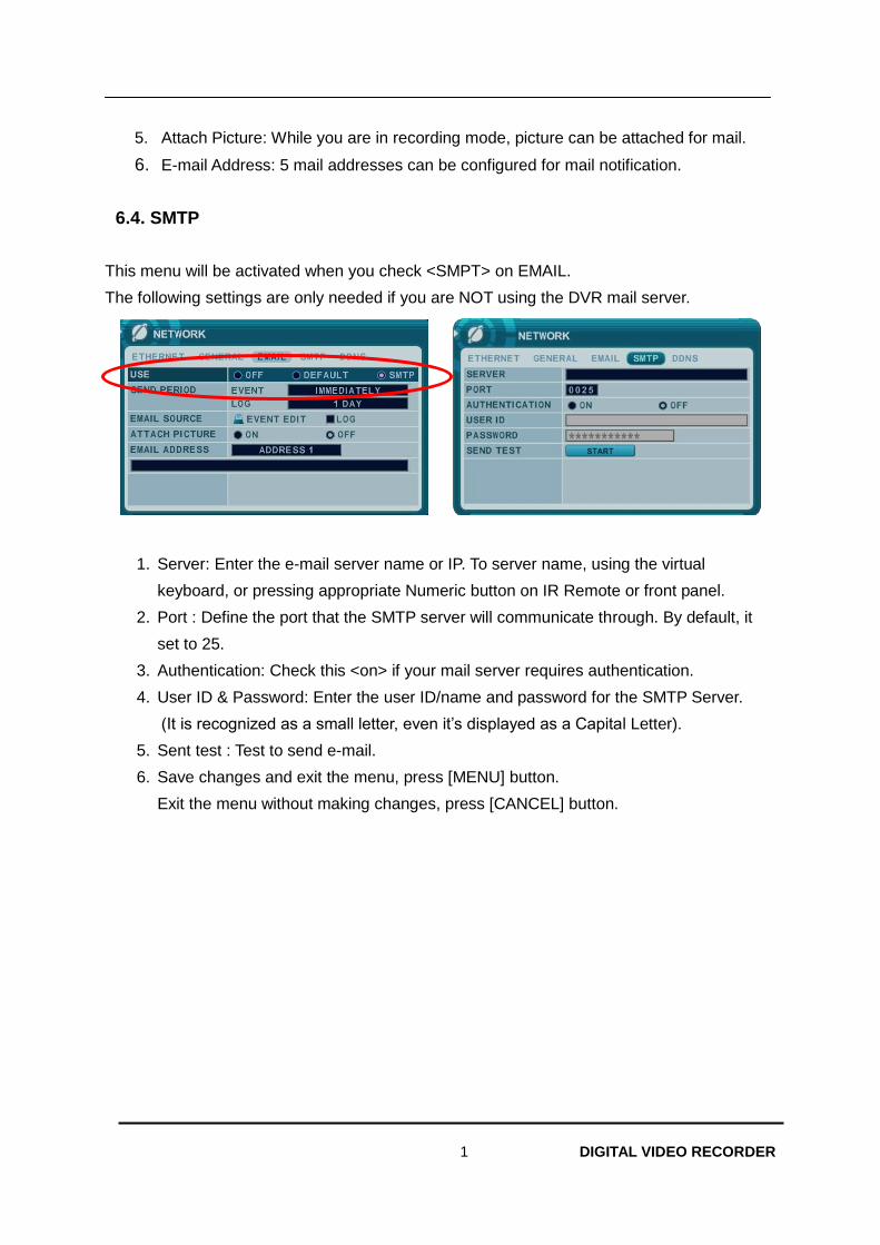
5. Attach Picture: While you are in recording mode, picture can be attached for mail.
6. E-mail Address: 5 mail addresses can be configured for mail notification.
6.4. SMTP
This menu will be activated when you check <SMPT> on EMAIL.
The following settings are only needed if you are NOT using the DVR mail server.
1. Server: Enter the e-mail server name or IP. To server name, using the virtual
keyboard, or pressing appropriate Numeric button on IR Remote or front panel.
2. Port : Define the port that the SMTP server will communicate through. By default, it
set to 25.
3. Authentication: Check this <on> if your mail server requires authentication.
4. User ID & Password: Enter the user ID/name and password for the SMTP Server.
(It is recognized as a small letter, even it’s displayed as a Capital Letter).
5. Sent test : Test to send e-mail.
6. Save changes and exit the menu, press [MENU] button.
Exit the menu without making changes, press [CANCEL] button.
2 DIGITAL VIDEO RECORDER
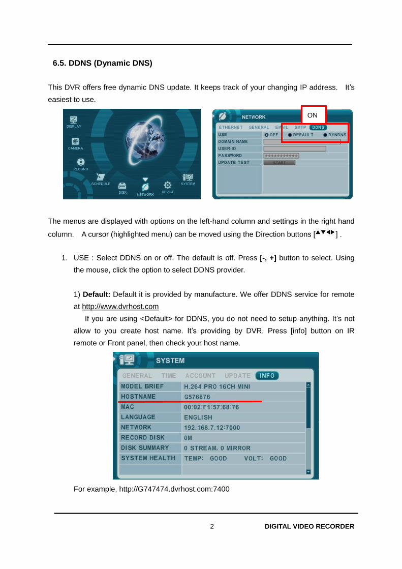
6.5. DDNS (Dynamic DNS)
This DVR offers free dynamic DNS update. It keeps track of your changing IP address. It’s
easiest to use.
The menus are displayed with options on the left-hand column and settings in the right hand
column. A cursor (highlighted menu) can be moved using the Direction buttons [ ] .
1. USE : Select DDNS on or off. The default is off. Press [-, +] button to select. Using
the mouse, click the option to select DDNS provider.
1) Default: Default it is provided by manufacture. We offer DDNS service for remote
at http://www.dvrhost.com
If you are using <Default> for DDNS, you do not need to setup anything. It’s not
allow to you create host name. It’s providing by DVR. Press [info] button on IR
remote or Front panel, then check your host name.
For example, http://G747474.dvrhost.com:7400
ON
3 DIGITAL VIDEO RECORDER
2) DYNDNS: To use your own domain name service or “dyndns.com”
2. The following settings are only needed if you are NOT using the default.
1) Domain Name: Enter the name you set for the DDNS web configuration.
2) User ID: Enter your user ID.
3) Password: Enter your password.
4) Update Test: Click the Update Test button to confirm the connection. A success
message will appear.
3. Save changes and exit the menu, press [MENU] button.
Exit the menu without making changes, press [CANCEL] button.
4 DIGITAL VIDEO RECORDER
6.6 Router & Port Forwarding
The majority of any network will often consist of a single IP address which shares the internet
access through a router. This IP address may be any external (public) static IP address or
any dynamic IP address issued by the Internet Service Provider.
The purpose of a router is to enable multiple personal computers and any other devices that
require internet connection to access the internet simultaneously. Most routers by default
enable (open) commonly used ports so that mainstream applications such as Hypertext
Transfer Protocol (HTTP, Port 80), File Transfer Protocol (FTP, Port 21), Telnet (Port 23) and
Post Office Protocol 3 (POP3, Port 110) are used.
To solve the firewall problem and let visitor into the network, the user instructs the router to
allow traffic to pass through on a given port. This is known as Port Forwarding, as the router
forwards (directs) all internet requests on a specific port to the local machine. With port
forwarding, external visitors are able to connect to the DVR while other internal devices
remain protected.
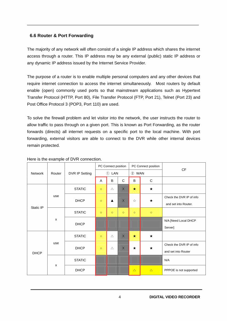
Here is the example of DVR connection.
Network Router DVR IP Setting
PC Connect position PC Connect position CF
① LAN ② WAN
A B C B C
Static IP
use
STATIC ○ △ X ★ ★
DHCP ○ ▲ X ☆ ★ Check the DVR IP of info
and set into Router.
x
STATIC ○ ○ ○ ○ ○
DHCP N/A [Need Local DHCP
Server]
DHCP
use
STATIC ○ △ X ★ ★
DHCP ○ △ X ★ ★ Check the DVR IP of info
and set into Router
x
STATIC N/A
DHCP △ △ PPPOE is not supported
5 DIGITAL VIDEO RECORDER
1) Description of Location.
A. LAN: Connect by Local IP. If you are connection from within your network, you only
need to enter the IP address of the system into the S/W (ex. 192.168.0.50)
B. WAN: Connect by DDNS. If you are connecting from outside your network, use the
DDNS to configure the S/W.(Ex. L123456.dvrhost.com).
C. WAN: Connect by IP address. If you are connecting from outside your network and if
you know your Static IP address , use the IP address to configure the S/W. (Ex.
http://124.137.23.72:6000 )
2) Description of Symbols.
○ : Connected.
x : Not able to connect
△: There’s some limitation depends on Router or Network connection
★ : Need to use Port Forwarding
3) Description of Color.
Yellow - Recommended
Grey - Non available
White – Depends on Router or Network condition.
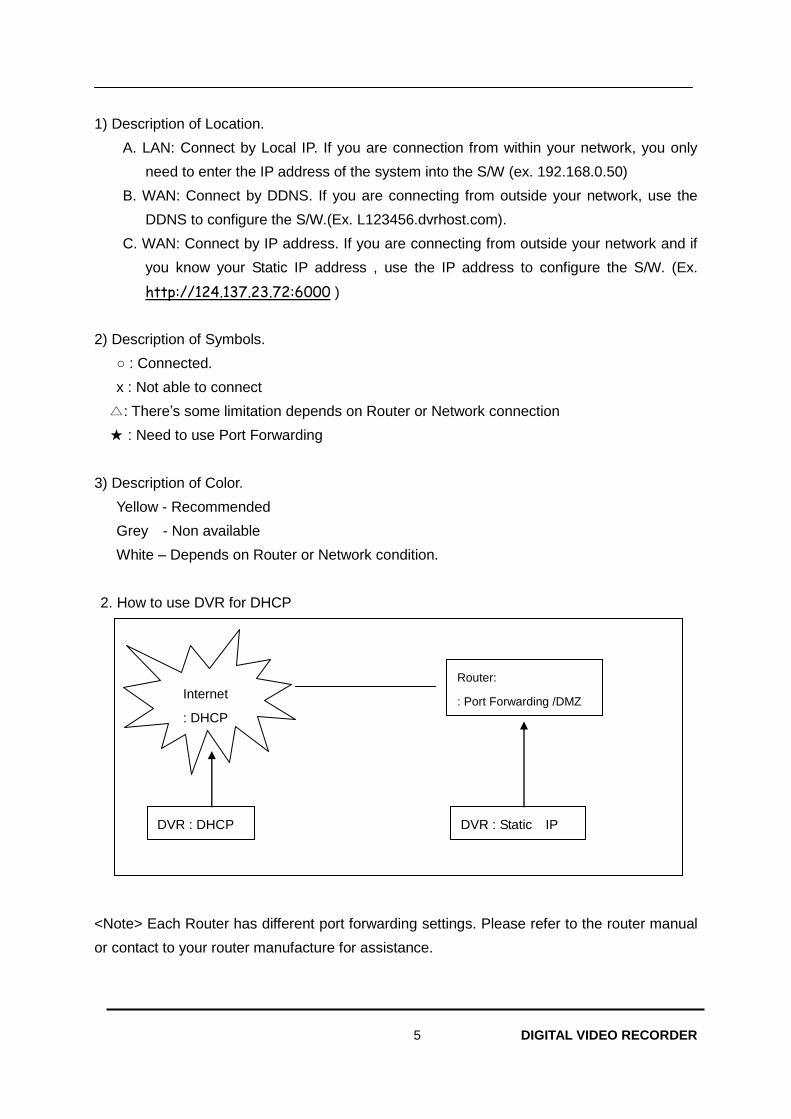
2. How to use DVR for DHCP
<Note> Each Router has different port forwarding settings. Please refer to the router manual
or contact to your router manufacture for assistance.
Internet
: DHCP
DVR : DHCP
Router:
: Port Forwarding /DMZ
DVR : Static IP
6 DIGITAL VIDEO RECORDER
7. DEVICE
7.1. GENERAL
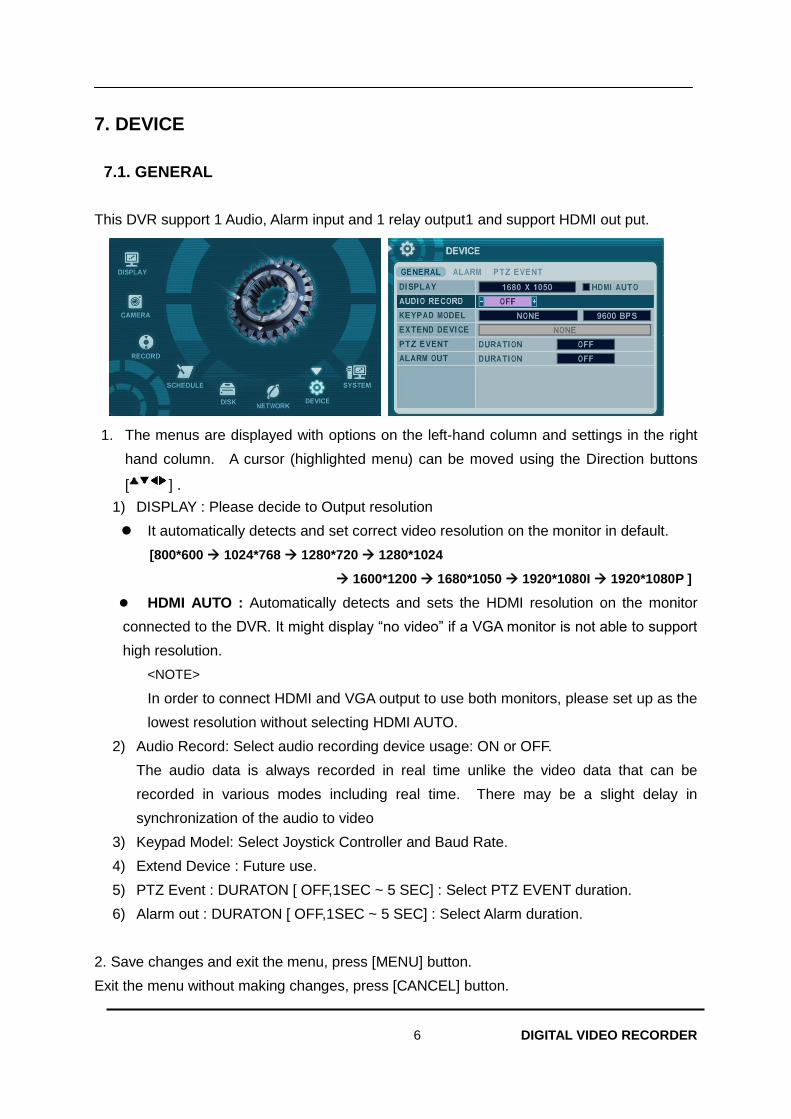
This DVR support 1 Audio, Alarm input and 1 relay output1 and support HDMI out put.
1. The menus are displayed with options on the left-hand column and settings in the right
hand column. A cursor (highlighted menu) can be moved using the Direction buttons
[ ] .
1) DISPLAY : Please decide to Output resolution
It automatically detects and set correct video resolution on the monitor in default.
[800*600 1024*768 1280*720 1280*1024
1600*1200 1680*1050 1920*1080I 1920*1080P ]
HDMI AUTO : Automatically detects and sets the HDMI resolution on the monitor
connected to the DVR. It might display “no video” if a VGA monitor is not able to support
high resolution.
<NOTE>
In order to connect HDMI and VGA output to use both monitors, please set up as the
lowest resolution without selecting HDMI AUTO.
2) Audio Record: Select audio recording device usage: ON or OFF.
The audio data is always recorded in real time unlike the video data that can be
recorded in various modes including real time. There may be a slight delay in
synchronization of the audio to video
3) Keypad Model: Select Joystick Controller and Baud Rate.
4) Extend Device : Future use.
5) PTZ Event : DURATON [ OFF,1SEC ~ 5 SEC] : Select PTZ EVENT duration.
6) Alarm out : DURATON [ OFF,1SEC ~ 5 SEC] : Select Alarm duration.
2. Save changes and exit the menu, press [MENU] button.
Exit the menu without making changes, press [CANCEL] button.
7 DIGITAL VIDEO RECORDER
7.2. ALARM
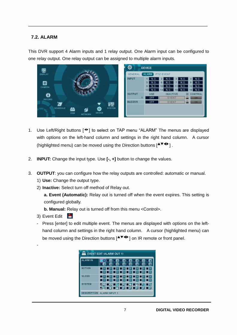
This DVR support 4 Alarm inputs and 1 relay output. One Alarm input can be configured to
one relay output. One relay output can be assigned to multiple alarm inputs.
1. Use Left/Right buttons [ ] to select on TAP menu “ALARM” The menus are displayed
with options on the left-hand column and settings in the right hand column. A cursor
(highlighted menu) can be moved using the Direction buttons [ ] .
2. INPUT: Change the input type. Use [-, +] button to change the values.
3. OUTPUT: you can configure how the relay outputs are controlled: automatic or manual.
1) Use: Change the output type.
2) Inactive: Select turn off method of Relay out.
a. Event (Automatic): Relay out is turned off when the event expires. This setting is
configured globally.
b. Manual: Relay out is turned off from this menu <Control>.
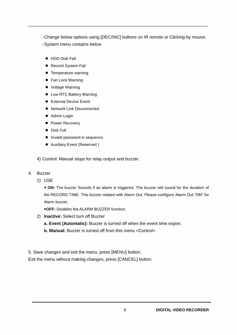
3) Event Edit
- Press [enter] to edit multiple event. The menus are displayed with options on the left-
hand column and settings in the right hand column. A cursor (highlighted menu) can
be moved using the Direction buttons [ ] on IR remote or front panel.
-
8 DIGITAL VIDEO RECORDER
- Change below options using [DEC/INC] buttons on IR remote or Clicking by mouse.
- System menu contains below
HDD Disk Fail
Record System Fail
Temperature warning.
Fan Lock Warning
Voltage Warning
Low RTC Battery Warning
External Device Event
Network Link Disconnected
Admin Login
Power Recovery
Disk Full
Invalid password in sequence
Auxiliary Event (Reserved )
4) Control: Manual stops for relay output and buzzer.
4. Buzzer
1) USE
ON: The buzzer Sounds if an alarm is triggered. The buzzer will sound for the duration of
the RECORD TIME. This buzzer related with Alarm Out. Please configure Alarm Out “ON” for
Alarm buzzer.
OFF: Disables the ALARM BUZZER function.
2) Inactive: Select turn off Buzzer
a. Event (Automatic): Buzzer is turned off when the event time expire.
b. Manual: Buzzer is turned off from this menu <Control>.
5. Save changes and exit the menu, press [MENU] button.
Exit the menu without making changes, press [CANCEL] button.
9 DIGITAL VIDEO RECORDER
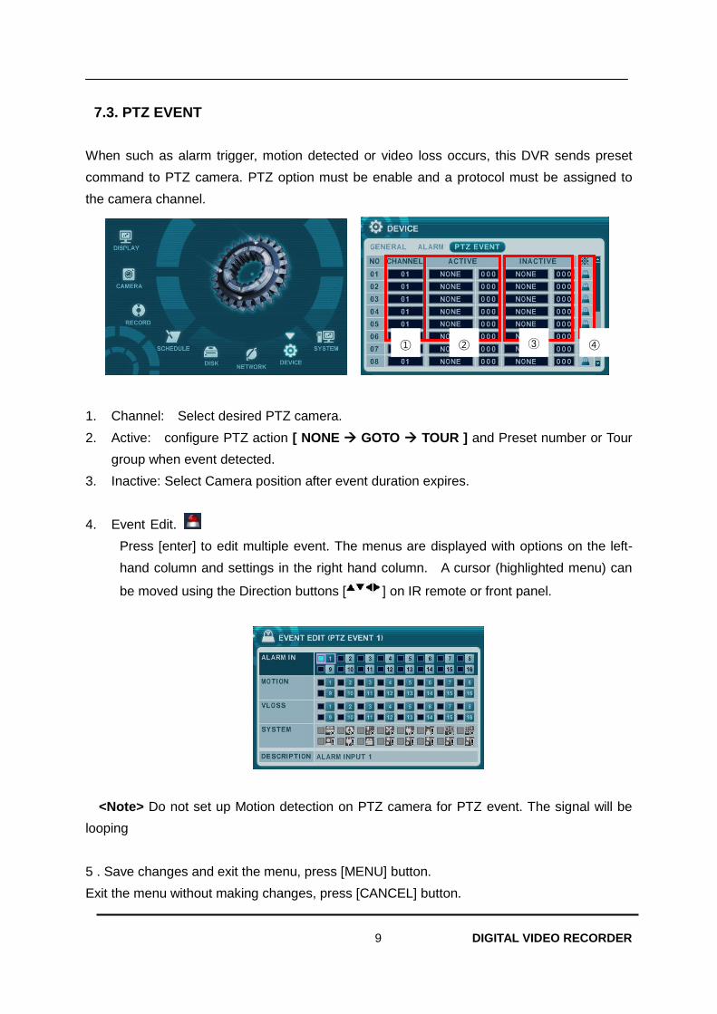
7.3. PTZ EVENT
When such as alarm trigger, motion detected or video loss occurs, this DVR sends preset
command to PTZ camera. PTZ option must be enable and a protocol must be assigned to
the camera channel.
1. Channel: Select desired PTZ camera.
2. Active: configure PTZ action [ NONE GOTO TOUR ] and Preset number or Tour
group when event detected.
3. Inactive: Select Camera position after event duration expires.
4. Event Edit.
Press [enter] to edit multiple event. The menus are displayed with options on the left-
hand column and settings in the right hand column. A cursor (highlighted menu) can
be moved using the Direction buttons [ ] on IR remote or front panel.
<Note> Do not set up Motion detection on PTZ camera for PTZ event. The signal will be
looping
5 . Save changes and exit the menu, press [MENU] button.
Exit the menu without making changes, press [CANCEL] button.
③ ④ ① ②
10 DIGITAL VIDEO RECORDER
8. SYSTEM
8.1. GENERAL
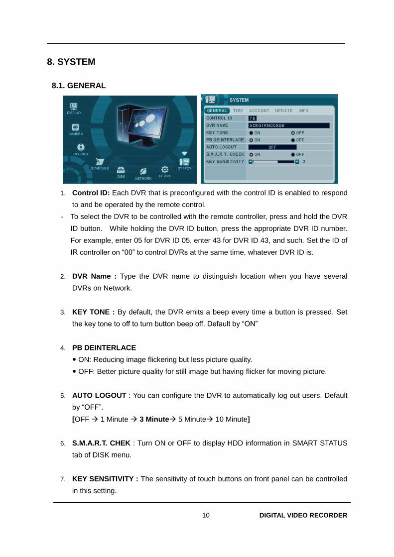
1. Control ID: Each DVR that is preconfigured with the control ID is enabled to respond
to and be operated by the remote control.
- To select the DVR to be controlled with the remote controller, press and hold the DVR
ID button. While holding the DVR ID button, press the appropriate DVR ID number.
For example, enter 05 for DVR ID 05, enter 43 for DVR ID 43, and such. Set the ID of
IR controller on “00” to control DVRs at the same time, whatever DVR ID is.
2. DVR Name : Type the DVR name to distinguish location when you have several
DVRs on Network.
3. KEY TONE : By default, the DVR emits a beep every time a button is pressed. Set
the key tone to off to turn button beep off. Default by “ON”
4. PB DEINTERLACE
ON: Reducing image flickering but less picture quality.
OFF: Better picture quality for still image but having flicker for moving picture.
5. AUTO LOGOUT : You can configure the DVR to automatically log out users. Default
by “OFF”.
[OFF 1 Minute 3 Minute 5 Minute 10 Minute]
6. S.M.A.R.T. CHEK : Turn ON or OFF to display HDD information in SMART STATUS
tab of DISK menu.
7. KEY SENSITIVITY : The sensitivity of touch buttons on front panel can be controlled
in this setting.
11 DIGITAL VIDEO RECORDER
8.2. TIME
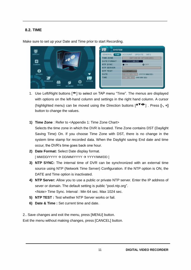
Make sure to set up your Date and Time prior to start Recording.
1. Use Left/Right buttons [ ] to select on TAP menu “Time”. The menus are displayed
with options on the left-hand column and settings in the right hand column. A cursor
(highlighted menu) can be moved using the Direction buttons [ ] . Press [-, +]
button to change the values.
1) Time Zone : Refer to <Appendix 1: Time Zone Chart>
Selects the time zone in which the DVR is located. Time Zone contains DST (Daylight
Saving Time) On. If you choose Time Zone with DST, there is no change in the
system time stamp for recorded data. When the Daylight saving End date and time
occur, the DVR’s time goes back one hour.
2) Date Format: Select Date display format.
[ MM/DD/YYYY DD/MM/YYYY YYYY/MM/DD ]
3) NTP SYNC: The internal time of DVR can be synchronized with an external time
source using NTP (Network Time Server) Configuration. If the NTP option is ON, the
DATE and Time option is inactivated.
4) NTP Server: Allow you to use a public or private NTP server. Enter the IP address of
sever or domain. The default setting is public “pool.ntp.org”.
<Note> Time Sync. Interval : Min 64 sec. Max 1024 sec.
5) NTP TEST : Test whether NTP Server works or fail.
6) Date & Time : Set current time and date.
2.. Save changes and exit the menu, press [MENU] button.
Exit the menu without making changes, press [CANCEL] button.
12 DIGITAL VIDEO RECORDER
8.3. ACCOUNT
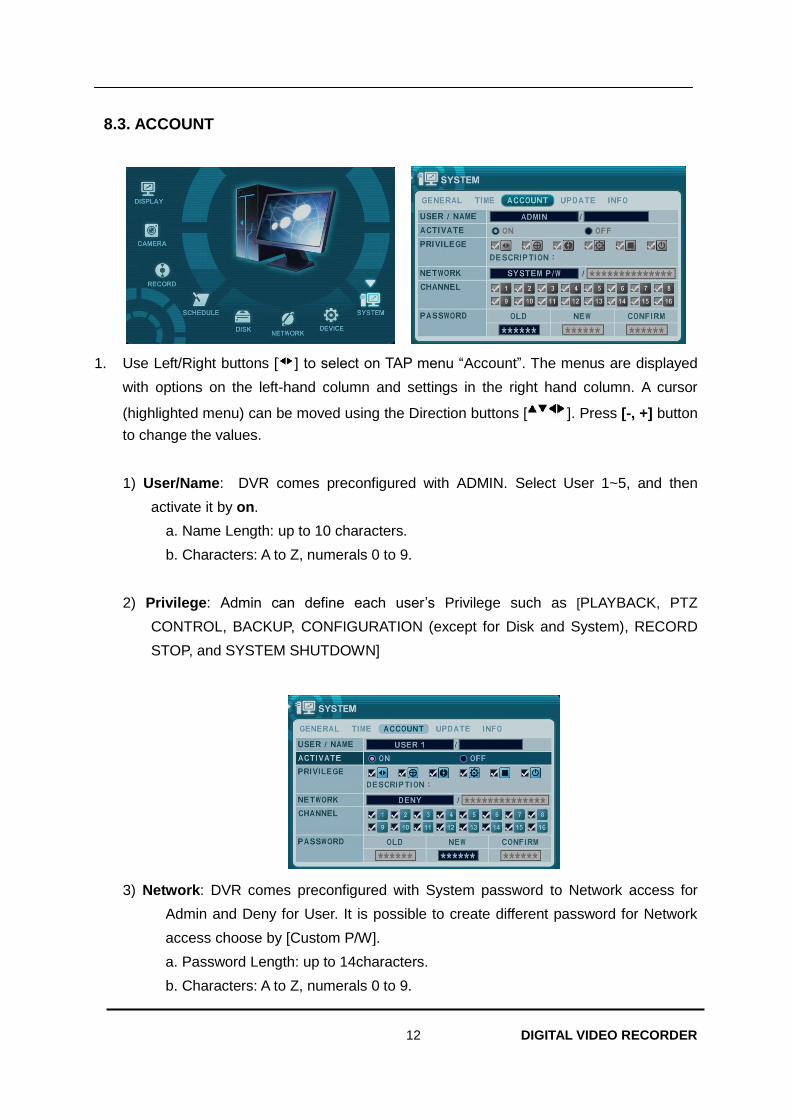
1. Use Left/Right buttons [ ] to select on TAP menu “Account”. The menus are displayed
with options on the left-hand column and settings in the right hand column. A cursor
(highlighted menu) can be moved using the Direction buttons [ ]. Press [-, +] button
to change the values.
1) User/Name: DVR comes preconfigured with ADMIN. Select User 1~5, and then
activate it by on.
a. Name Length: up to 10 characters.
b. Characters: A to Z, numerals 0 to 9.
2) Privilege: Admin can define each user’s Privilege such as [PLAYBACK, PTZ
CONTROL, BACKUP, CONFIGURATION (except for Disk and System), RECORD
STOP, and SYSTEM SHUTDOWN]
3) Network: DVR comes preconfigured with System password to Network access for
Admin and Deny for User. It is possible to create different password for Network
access choose by [Custom P/W].
a. Password Length: up to 14characters.
b. Characters: A to Z, numerals 0 to 9.
13 DIGITAL VIDEO RECORDER
4) Channel
Allow each user for different live monitoring.
5) Password
Enter the 6 numbers for the new password, and then re-enter the same password
under COMFIRM section. The asterisk is displayed for each character entered.
2. Save changes and exit the menu, press [MENU] button.
Exit the menu without making changes, press [CANCEL] button.
14 DIGITAL VIDEO RECORDER
8.4. UPDATE
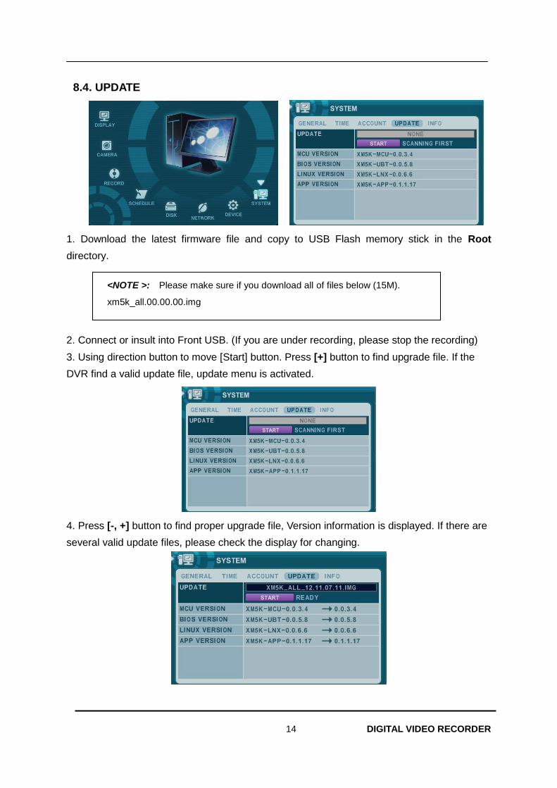
1. Download the latest firmware file and copy to USB Flash memory stick in the Root
directory.
2. Connect or insult into Front USB. (If you are under recording, please stop the recording)
3. Using direction button to move [Start] button. Press [+] button to find upgrade file. If the
DVR find a valid update file, update menu is activated.
4. Press [-, +] button to find proper upgrade file, Version information is displayed. If there are
several valid update files, please check the display for changing.
<NOTE >: Please make sure if you download all of files below (15M).
xm5k_all.00.00.00.img
15 DIGITAL VIDEO RECORDER
5. Using direction button to move [Start] button then press [+] button to start update
While it’s updating, ”in progress” message is displayed.
6. After the update process is complete, “Success” message is displayed. Press [+] button to
restart. The DVR issues a single beep, if Micom update included.
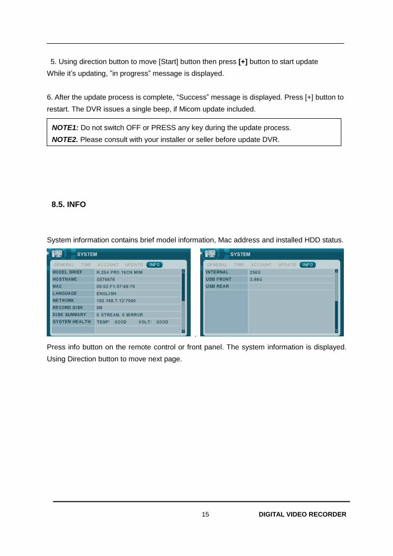
8.5. INFO
System information contains brief model information, Mac address and installed HDD status.
.
Press info button on the remote control or front panel. The system information is displayed.
Using Direction button to move next page.
NOTE1: Do not switch OFF or PRESS any key during the update process.
NOTE2. Please consult with your installer or seller before update DVR.
16 DIGITAL VIDEO RECORDER
VII. PAN/TILT ZOOM CONTROL
PTZ control is available for supported third-party dome cameras. The PTZ option must be
configured for each camera channel. For PTZ setup, refer to Camera Menu> PTZ setup.
The layout of the PTZ interface conforms to the layout of the front of the DVR or the remote
controller. Menu button is the guide anchor position for all other buttons. When in PTZ
interface mode, all buttons used for the PTZ related operation.
1. P.T.Z. Menu
1) To activate the Pan/Tilt Control, select the full screen display of the camera you wish
to control.
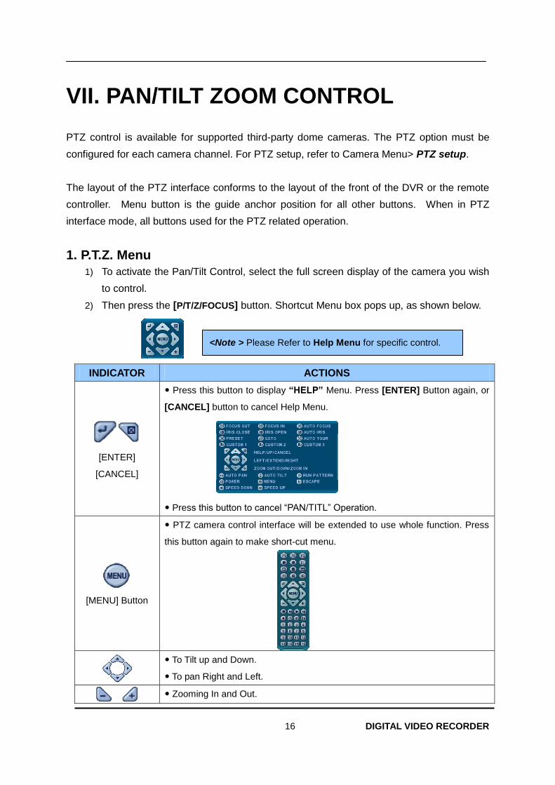
2) Then press the [P/T/Z/FOCUS] button. Shortcut Menu box pops up, as shown below.
INDICATOR ACTIONS
[ENTER]
[CANCEL]
Press this button to display “HELP” Menu. Press [ENTER] Button again, or
[CANCEL] button to cancel Help Menu.
Press this button to cancel “PAN/TITL” Operation.
[MENU] Button
PTZ camera control interface will be extended to use whole function. Press
this button again to make short-cut menu.
To Tilt up and Down.
To pan Right and Left.
Zooming In and Out.
<Note > Please Refer to Help Menu for specific control.
17 DIGITAL VIDEO RECORDER
1.1 How to control PTZ by mouse
User can control PTZ camera by mouse controller.
It follows mouse cursor instead of using direction button to move.
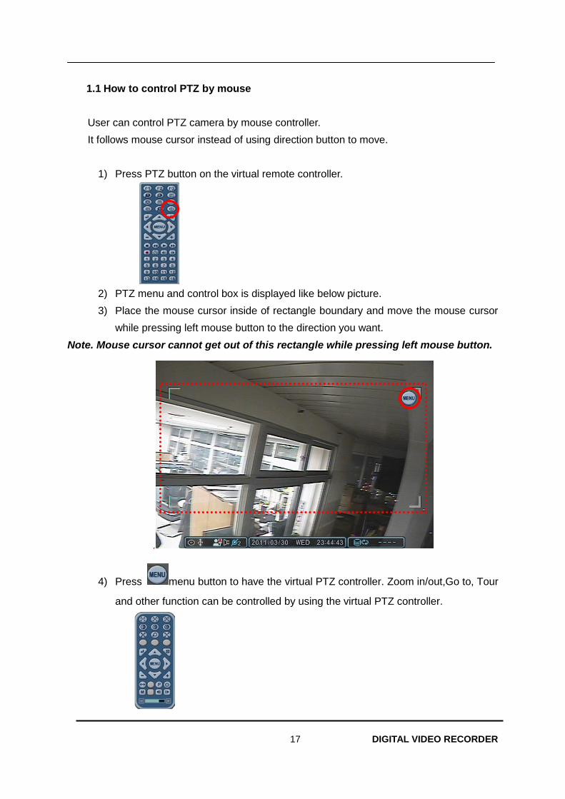
1) Press PTZ button on the virtual remote controller.
2) PTZ menu and control box is displayed like below picture.
3) Place the mouse cursor inside of rectangle boundary and move the mouse cursor
while pressing left mouse button to the direction you want.
Note. Mouse cursor cannot get out of this rectangle while pressing left mouse button.
.
4) Press menu button to have the virtual PTZ controller. Zoom in/out,Go to, Tour
and other function can be controlled by using the virtual PTZ controller.
18 DIGITAL VIDEO RECORDER
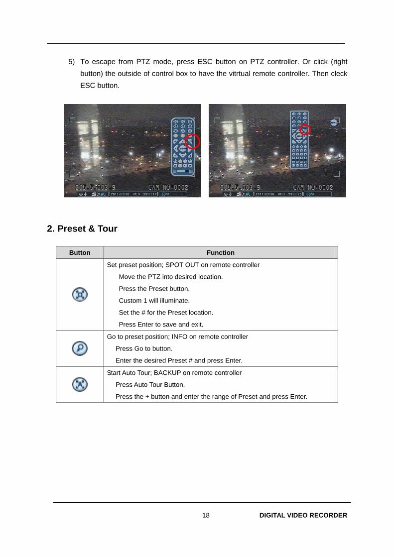
5) To escape from PTZ mode, press ESC button on PTZ controller. Or click (right
button) the outside of control box to have the vitrtual remote controller. Then cleck
ESC button.
2. Preset & Tour
Button Function
Set preset position; SPOT OUT on remote controller
a. Move the PTZ into desired location.
b. Press the Preset button.
c. Custom 1 will illuminate.
d. Set the # for the Preset location.
e. Press Enter to save and exit.
Go to preset position; INFO on remote controller
a. Press Go to button.
b. Enter the desired Preset # and press Enter.
Start Auto Tour; BACKUP on remote controller
a. Press Auto Tour Button.
b. Press the + button and enter the range of Preset and press Enter.
19 DIGITAL VIDEO RECORDER
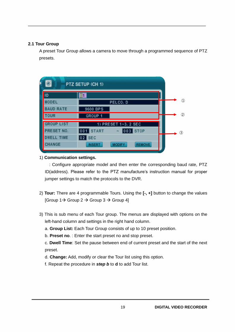
2.1 Tour Group
A preset Tour Group allows a camera to move through a programmed sequence of PTZ
presets.
1) Communication settings.
: Configure appropriate model and then enter the corresponding baud rate, PTZ
ID(address). Please refer to the PTZ manufacture’s instruction manual for proper
jumper settings to match the protocols to the DVR.
2) Tour: There are 4 programmable Tours. Using the [-, +] button to change the values
[Group 1 Group 2 Group 3 Group 4]
3) This is sub menu of each Tour group. The menus are displayed with options on the
left-hand column and settings in the right hand column.
a. Group List: Each Tour Group consists of up to 10 preset position.
b. Preset no. : Enter the start preset no and stop preset.
c. Dwell Time: Set the pause between end of current preset and the start of the next
preset.
d. Change: Add, modify or clear the Tour list using this option.
f. Repeat the procedure in step b to d to add Tour list.
①
③
②
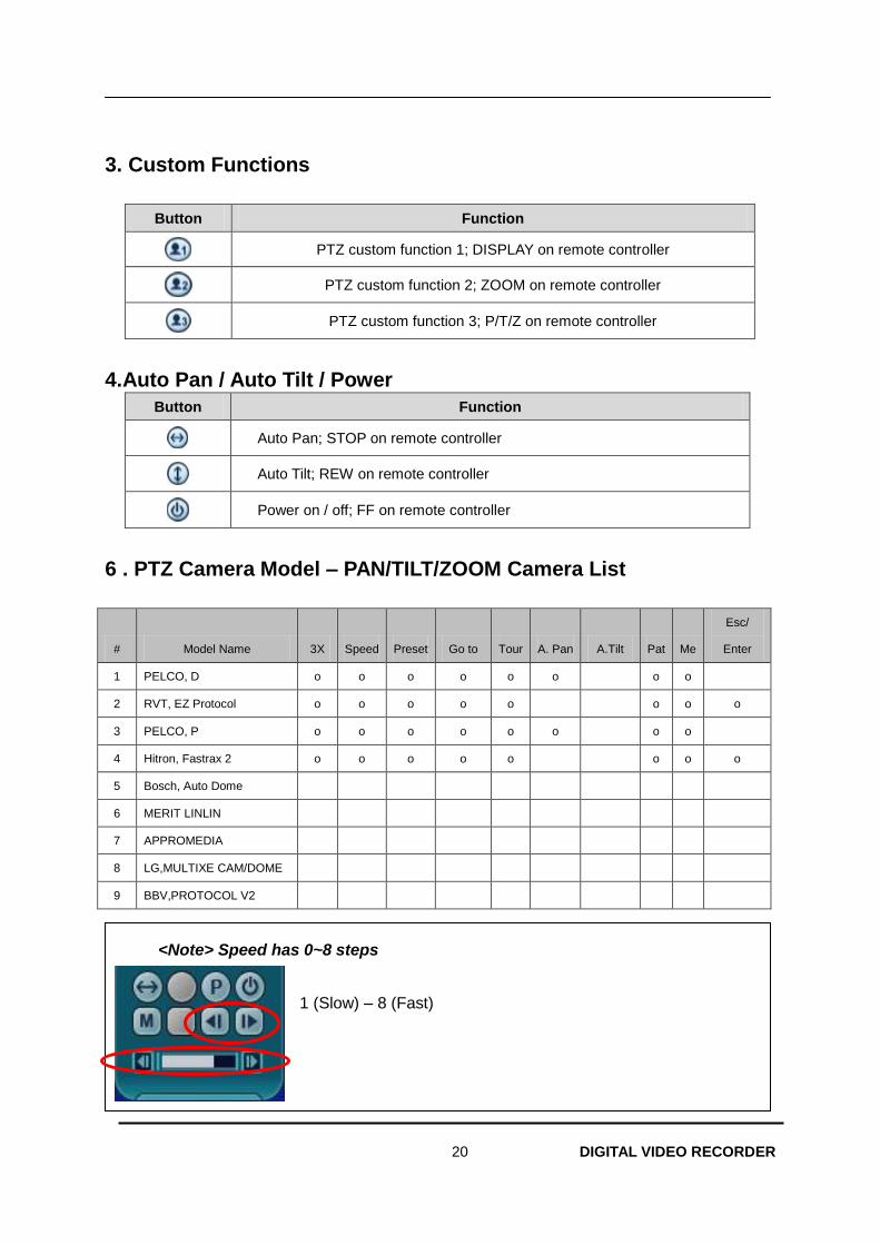
20 DIGITAL VIDEO RECORDER
3. Custom Functions
Button Function
PTZ custom function 1; DISPLAY on remote controller
PTZ custom function 2; ZOOM on remote controller
PTZ custom function 3; P/T/Z on remote controller
4.Auto Pan / Auto Tilt / Power
Button Function
Auto Pan; STOP on remote controller
Auto Tilt; REW on remote controller
Power on / off; FF on remote controller
6 . PTZ Camera Model – PAN/TILT/ZOOM Camera List
# Model Name 3X Speed Preset Go to Tour A. Pan A.Tilt Pat Me
Esc/
Enter
1 PELCO, D o o o o o o o o
2 RVT, EZ Protocol o o o o o o o o
3 PELCO, P o o o o o o o o
4 Hitron, Fastrax 2 o o o o o o o o
5 Bosch, Auto Dome
6 MERIT LINLIN
7 APPROMEDIA
8 LG,MULTIXE CAM/DOME
9 BBV,PROTOCOL V2
<Note> Speed has 0~8 steps
1 (Slow) – 8 (Fast)
21 DIGITAL VIDEO RECORDER
VIII.PLAYBACK /SEARCH
The DVR supports 2 playback mode; playback and Search. The DVR offers a variety of
search functions that enables you to quickly and efficiently locate and review a specific
period from the database. It supports three different search modes: Date/Time, Event, Event
Area , and Log search.
1. Playback
When the [PLAY] button is pressed, the DVR starts to play back any recorded data from
the latest data, whether in live or recording mode. When the DVR reaches the end of
the recorded data, it will stop the playback.
During the playback, the DVR may be played back in reverse, paused, speed search up
to 16 times the normal speed, or move picture by picture.
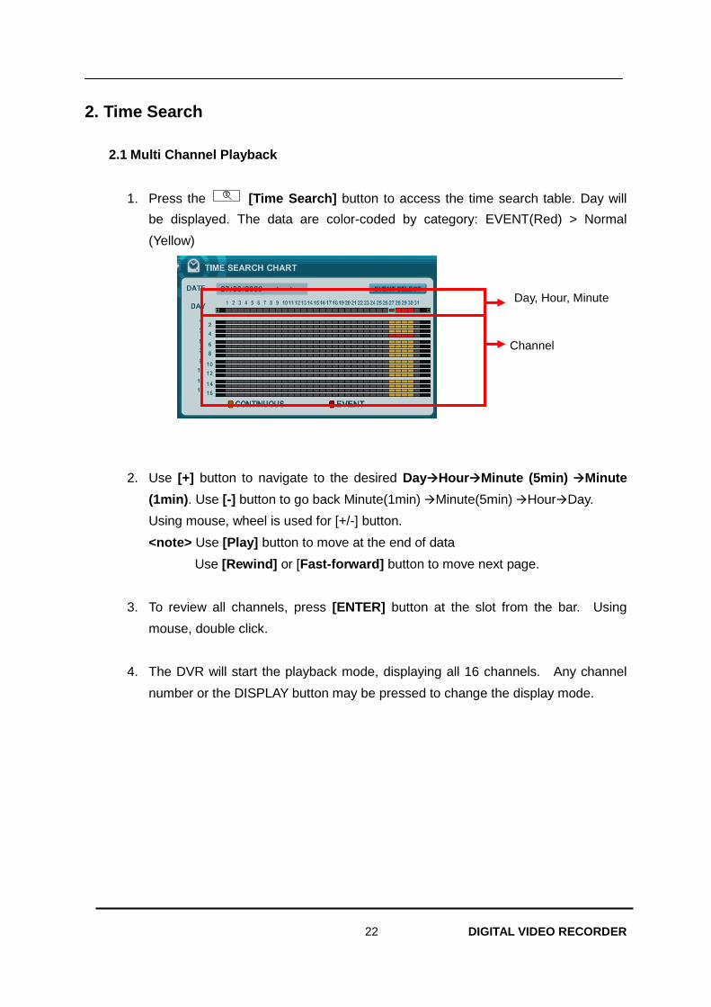
22 DIGITAL VIDEO RECORDER
2. Time Search
2.1 Multi Channel Playback
1. Press the T
[Time Search] button to access the time search table. Day will
be displayed. The data are color-coded by category: EVENT(Red) > Normal
(Yellow)
2. Use [+] button to navigate to the desired DayHourMinute (5min) Minute
(1min). Use [-] button to go back Minute(1min) Minute(5min) HourDay.
Using mouse, wheel is used for [+/-] button.
<note> Use [Play] button to move at the end of data
Use [Rewind] or [Fast-forward] button to move next page.
3. To review all channels, press [ENTER] button at the slot from the bar. Using
mouse, double click.
4. The DVR will start the playback mode, displaying all 16 channels. Any channel
number or the DISPLAY button may be pressed to change the display mode.
Day, Hour, Minute
Channel
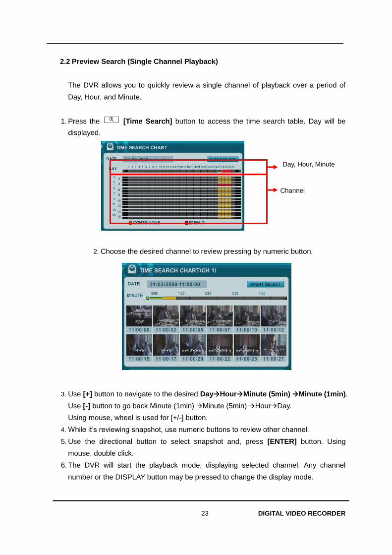
23 DIGITAL VIDEO RECORDER
2.2 Preview Search (Single Channel Playback)
The DVR allows you to quickly review a single channel of playback over a period of
Day, Hour, and Minute.
1. Press the T
[Time Search] button to access the time search table. Day will be
displayed.
2. Choose the desired channel to review pressing by numeric button.
3. Use [+] button to navigate to the desired DayHourMinute (5min) Minute (1min).
Use [-] button to go back Minute (1min) Minute (5min) HourDay.
Using mouse, wheel is used for [+/-] button.
4. While it’s reviewing snapshot, use numeric buttons to review other channel.
5. Use the directional button to select snapshot and, press [ENTER] button. Using
mouse, double click.
6. The DVR will start the playback mode, displaying selected channel. Any channel
number or the DISPLAY button may be pressed to change the display mode.
Day, Hour, Minute
Channel
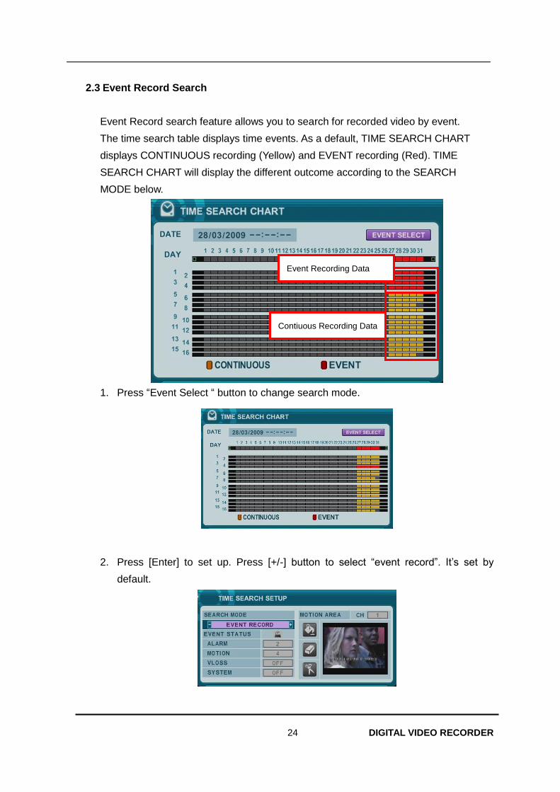
24 DIGITAL VIDEO RECORDER
2.3 Event Record Search
Event Record search feature allows you to search for recorded video by event.
The time search table displays time events. As a default, TIME SEARCH CHART
displays CONTINUOUS recording (Yellow) and EVENT recording (Red). TIME
SEARCH CHART will display the different outcome according to the SEARCH
MODE below.
1. Press “Event Select “ button to change search mode.
2. Press [Enter] to set up. Press [+/-] button to select “event record”. It’s set by
default.
Contiuous Recording Data
Event Recording Data
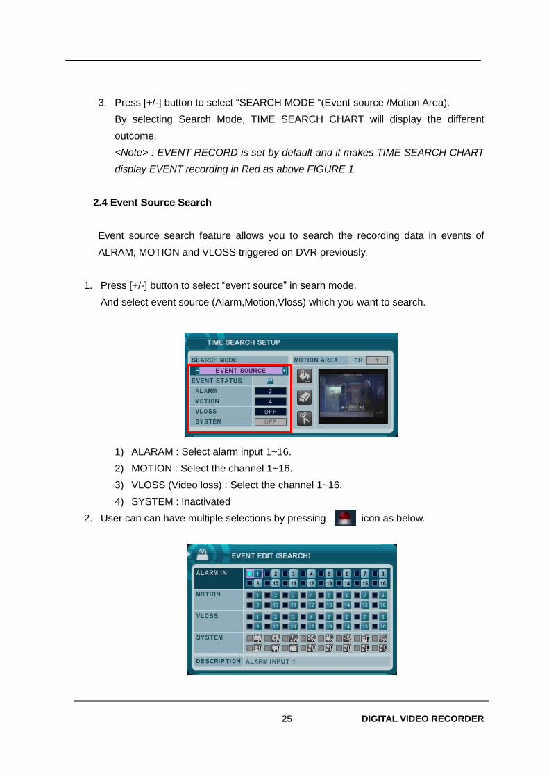
25 DIGITAL VIDEO RECORDER
3. Press [+/-] button to select “SEARCH MODE “(Event source /Motion Area).
By selecting Search Mode, TIME SEARCH CHART will display the different
outcome.
<Note> : EVENT RECORD is set by default and it makes TIME SEARCH CHART
display EVENT recording in Red as above FIGURE 1.
2.4 Event Source Search
Event source search feature allows you to search the recording data in events of
ALRAM, MOTION and VLOSS triggered on DVR previously.
1. Press [+/-] button to select “event source” in searh mode.
And select event source (Alarm,Motion,Vloss) which you want to search.
1) ALARAM : Select alarm input 1~16.
2) MOTION : Select the channel 1~16.
3) VLOSS (Video loss) : Select the channel 1~16.
4) SYSTEM : Inactivated
2. User can can have multiple selections by pressing icon as below.
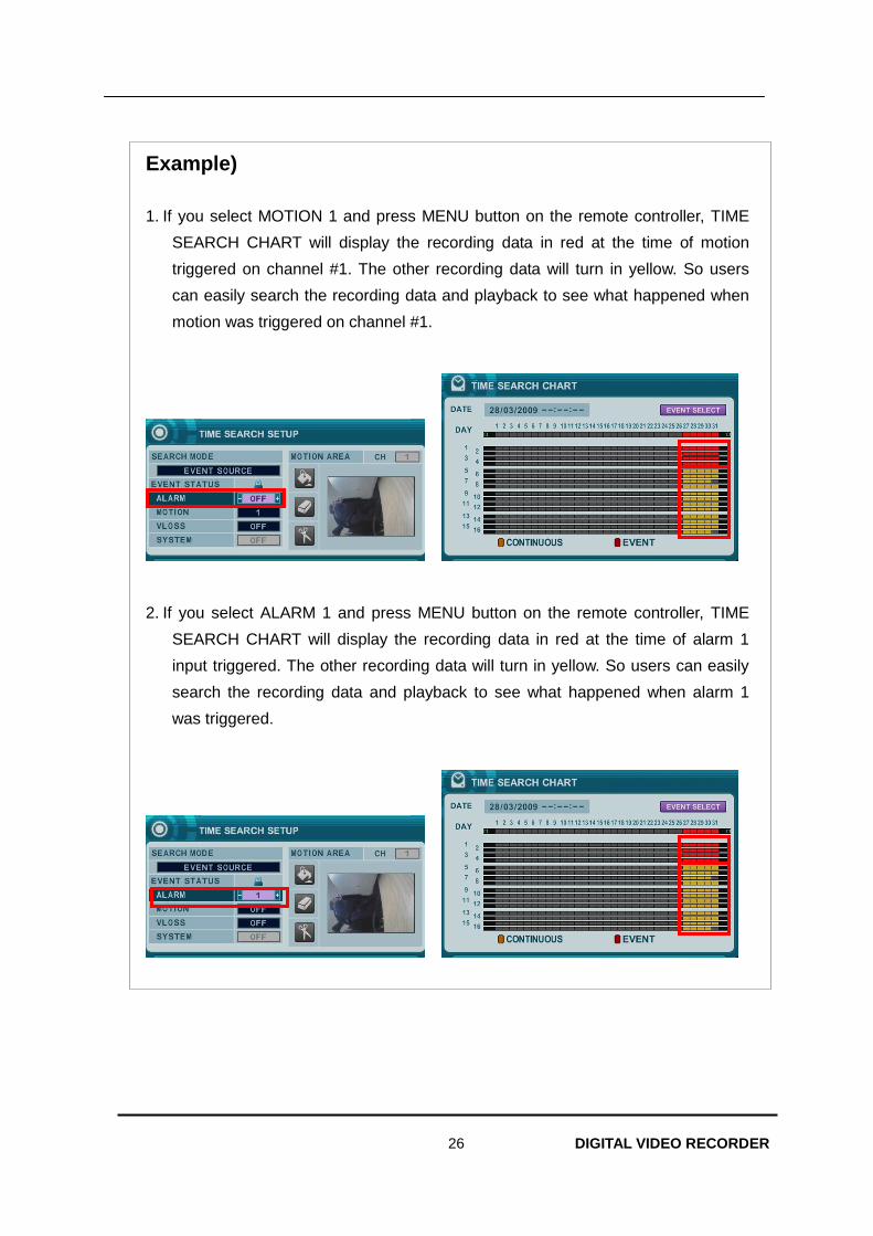
26 DIGITAL VIDEO RECORDER
Example)
1. If you select MOTION 1 and press MENU button on the remote controller, TIME
SEARCH CHART will display the recording data in red at the time of motion
triggered on channel #1. The other recording data will turn in yellow. So users
can easily search the recording data and playback to see what happened when
motion was triggered on channel #1.
2. If you select ALARM 1 and press MENU button on the remote controller, TIME
SEARCH CHART will display the recording data in red at the time of alarm 1
input triggered. The other recording data will turn in yellow. So users can easily
search the recording data and playback to see what happened when alarm 1
was triggered.

27 DIGITAL VIDEO RECORDER
2.5 Motion Area Search (Single Channel Playback)
The DVR searches for recorded video the matches the search area defined by selected
cell.
1. Select “MOTION AREA” (Single channel playback) to search the recording data that
has motion in a specific area in a certain channel.
2. By pressing [+/- ] button, select the channel you want to search.
3. Select motion area you want to search.
: : Select All. Press [Enter] to select.
: : Clear All. Press [Enter] to select.
: Select specific. Press [Enter] to select.
4. Press MENU button, then TIME SEARCH CHART will display the recording data in
red to see what happened in that channel.
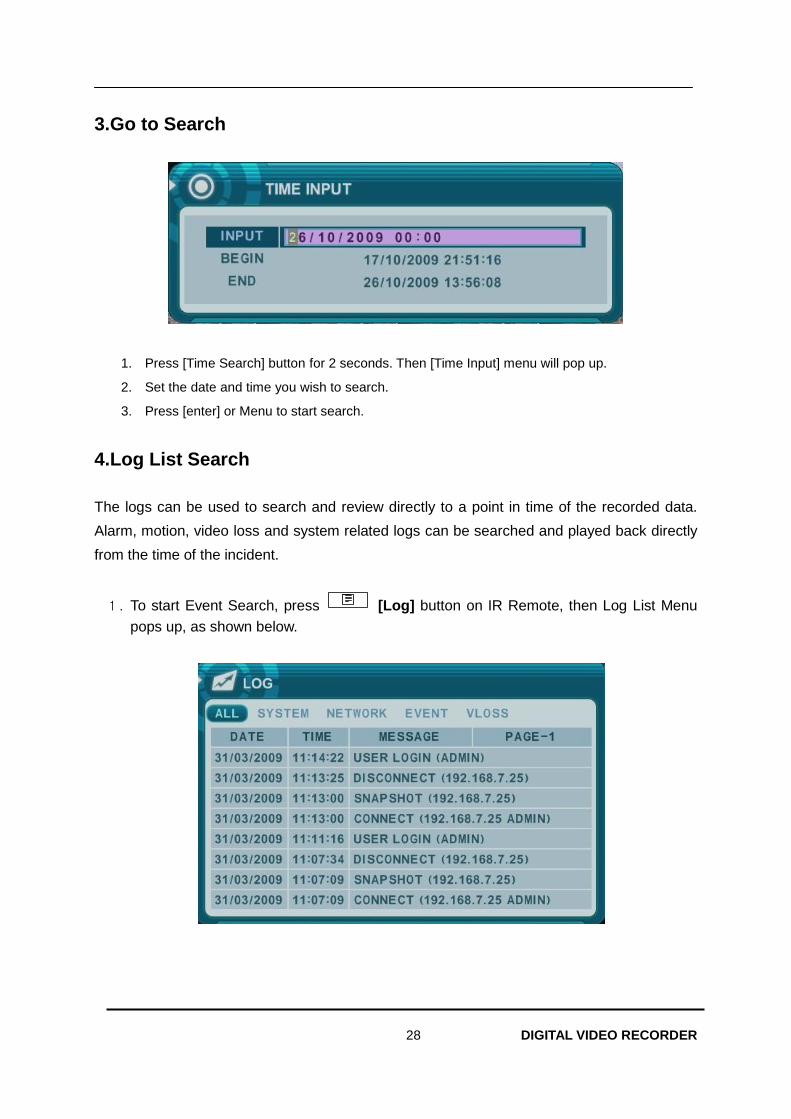
28 DIGITAL VIDEO RECORDER
3.Go to Search
1. Press [Time Search] button for 2 seconds. Then [Time Input] menu will pop up.
2. Set the date and time you wish to search.
3. Press [enter] or Menu to start search.
4.Log List Search
The logs can be used to search and review directly to a point in time of the recorded data.
Alarm, motion, video loss and system related logs can be searched and played back directly
from the time of the incident.
1. To start Event Search, press [Log] button on IR Remote, then Log List Menu
pops up, as shown below.
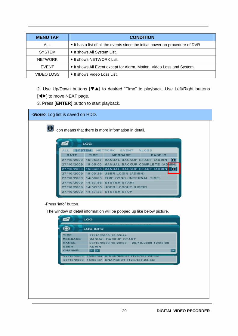
29 DIGITAL VIDEO RECORDER
MENU TAP CONDITION
ALL It has a list of all the events since the initial power on procedure of DVR
SYSTEM It shows All System List.
NETWORK It shows NETWORK List.
EVENT It shows All Event except for Alarm, Motion, Video Loss and System.
VIDEO LOSS It shows Video Loss List.
2. Use Up/Down buttons [] to desired “Time” to playback. Use Left/Right buttons
[] to move NEXT page.
3. Press [ENTER] button to start playback.
Detail log information.
icon means that there is more information in detail.
-Press ‘info” button.
The window of detail information will be popped up like below picture.
<Note> Log list is saved on HDD.
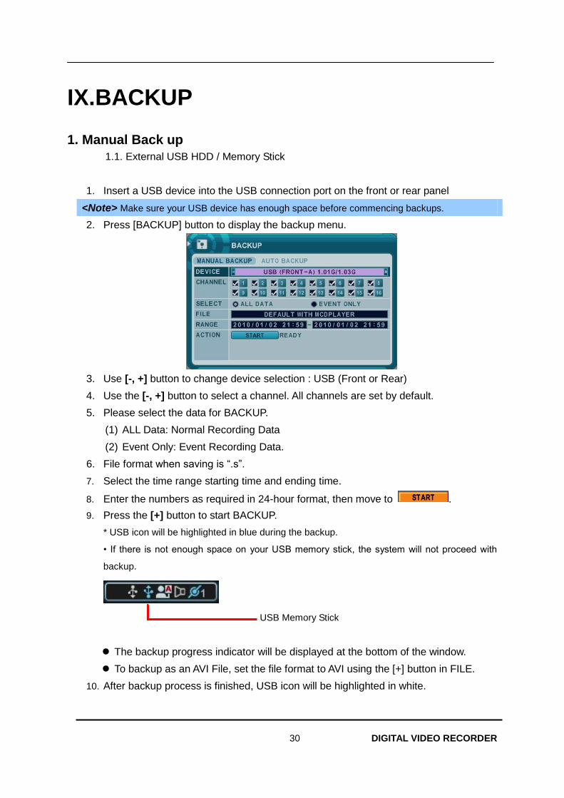
30 DIGITAL VIDEO RECORDER
IX.BACKUP
1. Manual Back up
1.1. External USB HDD / Memory Stick
1. Insert a USB device into the USB connection port on the front or rear panel
<Note> Make sure your USB device has enough space before commencing backups.
2. Press [BACKUP] button to display the backup menu.
3. Use [-, +] button to change device selection : USB (Front or Rear)
4. Use the [-, +] button to select a channel. All channels are set by default.
5. Please select the data for BACKUP.
(1) ALL Data: Normal Recording Data
(2) Event Only: Event Recording Data.
6. File format when saving is “.s”.
7. Select the time range starting time and ending time.
8. Enter the numbers as required in 24-hour format, then move to .
9. Press the [+] button to start BACKUP.
* USB icon will be highlighted in blue during the backup.
• If there is not enough space on your USB memory stick, the system will not proceed with
backup.
USB Memory Stick
The backup progress indicator will be displayed at the bottom of the window.
To backup as an AVI File, set the file format to AVI using the [+] button in FILE.
10. After backup process is finished, USB icon will be highlighted in white.
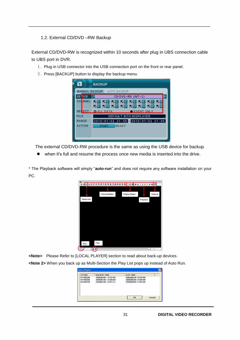
31 DIGITAL VIDEO RECORDER
1.2. External CD/DVD –RW Backup
External CD/DVD-RW is recognized within 10 seconds after plug in UBS connection cable
to UBS port in DVR.
1. Plug in USB connector into the USB connection port on the front or rear panel.
2. Press [BACKUP] button to display the backup menu.
The external CD/DVD-RW procedure is the same as using the USB device for backup.
when it’s full and resume the process once new media is inserted into the drive.
* The Playback software will simply “auto-run” and does not require any software installation on your
PC.
<Note> Please Refer to [LOCAL PLAYER] section to read about back-up devices.
<Note 2> When you back up as Multi-Section the Play List pops up instead of Auto Run.
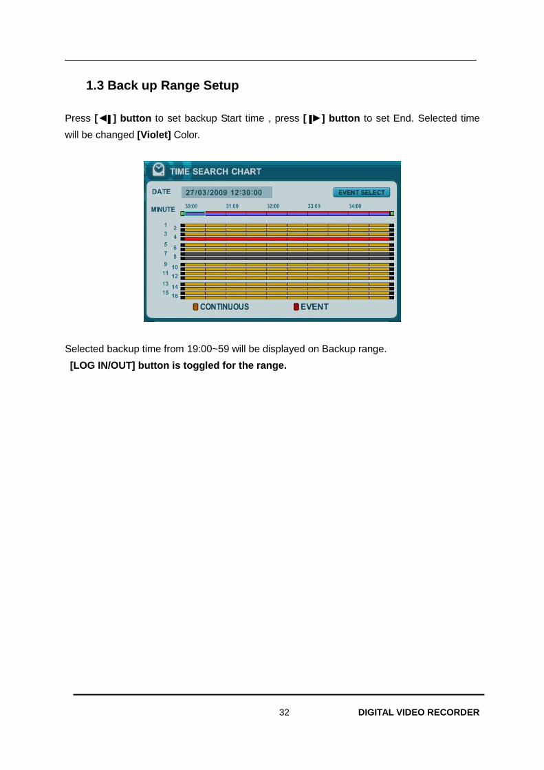
32 DIGITAL VIDEO RECORDER
1.3 Back up Range Setup
Press [◄▌] button to set backup Start time , press [▐►] button to set End. Selected time
will be changed [Violet] Color.
Selected backup time from 19:00~59 will be displayed on Backup range.
[LOG IN/OUT] button is toggled for the range.
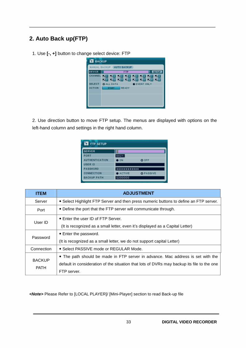
33 DIGITAL VIDEO RECORDER
2. Auto Back up(FTP)
1. Use [-, +] button to change select device: FTP
2. Use direction button to move FTP setup. The menus are displayed with options on the
left-hand column and settings in the right hand column.
<Note> Please Refer to [LOCAL PLAYER]/ [Mini-Player] section to read Back-up file
ITEM ADJUSTMENT
Server Select Highlight FTP Server and then press numeric buttons to define an FTP server.
Port Define the port that the FTP server will communicate through.
User ID Enter the user ID of FTP Server.
(It is recognized as a small letter, even it’s displayed as a Capital Letter)
Password Enter the password.
(It is recognized as a small letter, we do not support capital Letter)
Connection Select PASSIVE mode or REGULAR Mode.
BACKUP
PATH
The path should be made in FTP server in advance. Mac address is set with the
default in consideration of the situation that lots of DVRs may backup its file to the one
FTP server.
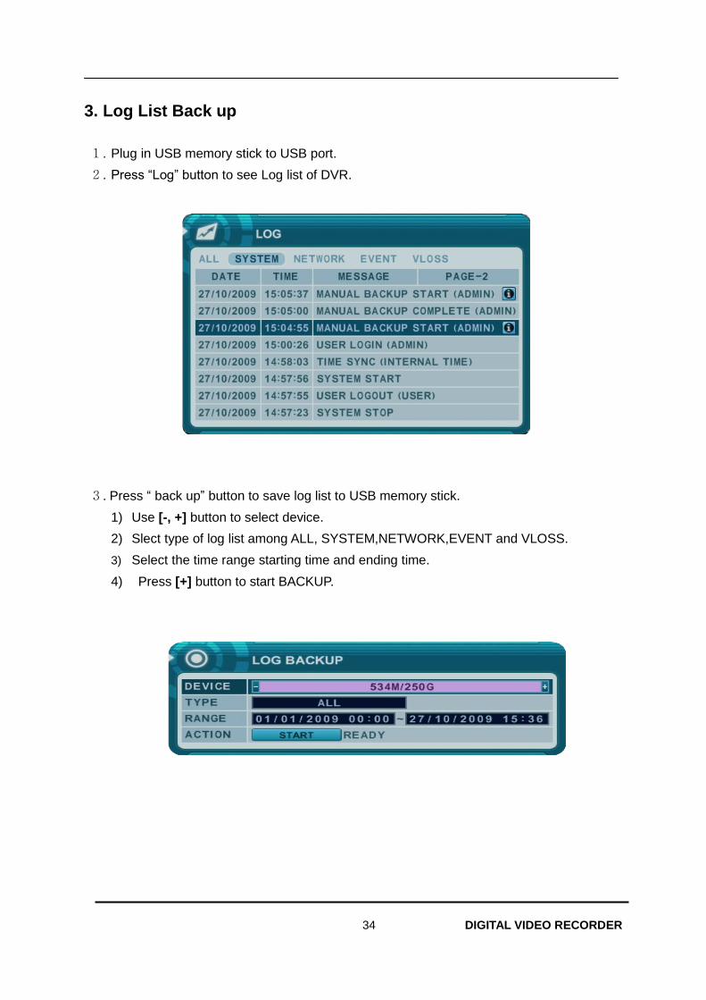
34 DIGITAL VIDEO RECORDER
3. Log List Back up
1. Plug in USB memory stick to USB port.
2. Press “Log” button to see Log list of DVR.
3. Press “ back up” button to save log list to USB memory stick.
1) Use [-, +] button to select device.
2) Slect type of log list among ALL, SYSTEM,NETWORK,EVENT and VLOSS.
3) Select the time range starting time and ending time.
4) Press [+] button to start BACKUP.
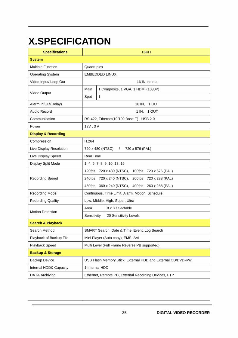
35 DIGITAL VIDEO RECORDER
X.SPECIFICATION Specifications 16CH
System
Multiple Function Quadruplex
Operating System EMBEDDED LINUX
Video Input/ Loop Out 16 IN, no out
Video Output Main 1 Composite, 1 VGA, 1 HDMI (1080P)
Spot 1
Alarm In/Out(Relay) 16 IN, 1 OUT
Audio Record 1 IN, 1 OUT
Communication RS-422, Ethernet(10/100 Base-T) , USB 2.0
Power 12V , 3 A
Display & Recording
Compression H.264
Live Display Resolution 720 x 480 (NTSC) / 720 x 576 (PAL)
Live Display Speed Real Time
Display Split Mode 1, 4, 6, 7, 8, 9, 10, 13, 16
Recording Speed
120fps 720 x 480 (NTSC), 100fps 720 x 576 (PAL)
240fps 720 x 240 (NTSC), 200fps 720 x 288 (PAL)
480fps 360 x 240 (NTSC), 400fps 260 x 288 (PAL)
Recording Mode Continuous, Time Limit, Alarm, Motion, Schedule
Recording Quality Low, Middle, High, Super, Ultra
Motion Detection Area 8 x 8 selectable
Sensitivity 20 Sensitivity Levels
Search & Playback
Search Method SMART Search, Date & Time, Event, Log Search
Playback of Backup File Mini Player (Auto copy), EMS, AVI
Playback Speed Multi Level (Full Frame Reverse PB supported)
Backup & Storage
Backup Device USB Flash Memory Stick, External HDD and External CD/DVD-RW
Internal HDD& Capacity 1 Internal HDD
DATA Archiving Ethernet, Remote PC, External Recording Devices, FTP
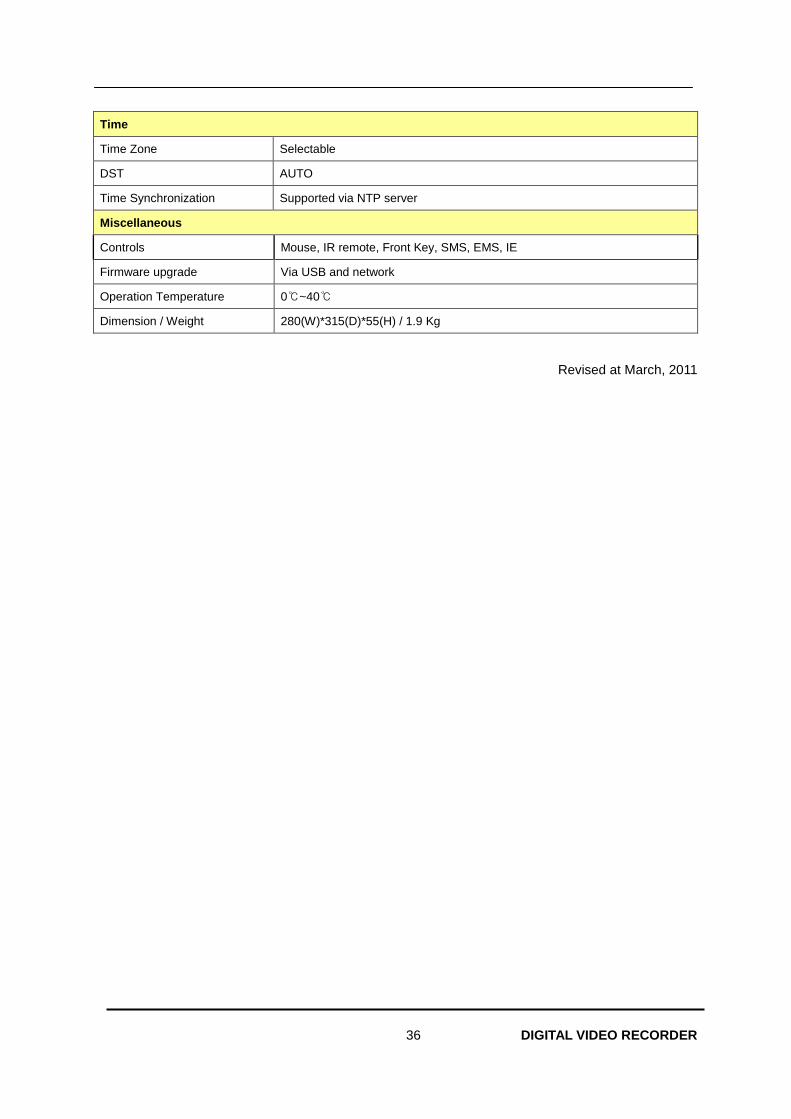
36 DIGITAL VIDEO RECORDER
Time
Time Zone Selectable
DST AUTO
Time Synchronization Supported via NTP server
Miscellaneous
Controls Mouse, IR remote, Front Key, SMS, EMS, IE
Firmware upgrade Via USB and network
Operation Temperature 0℃~40℃
Dimension / Weight 280(W)*315(D)*55(H) / 1.9 Kg
Revised at March, 2011
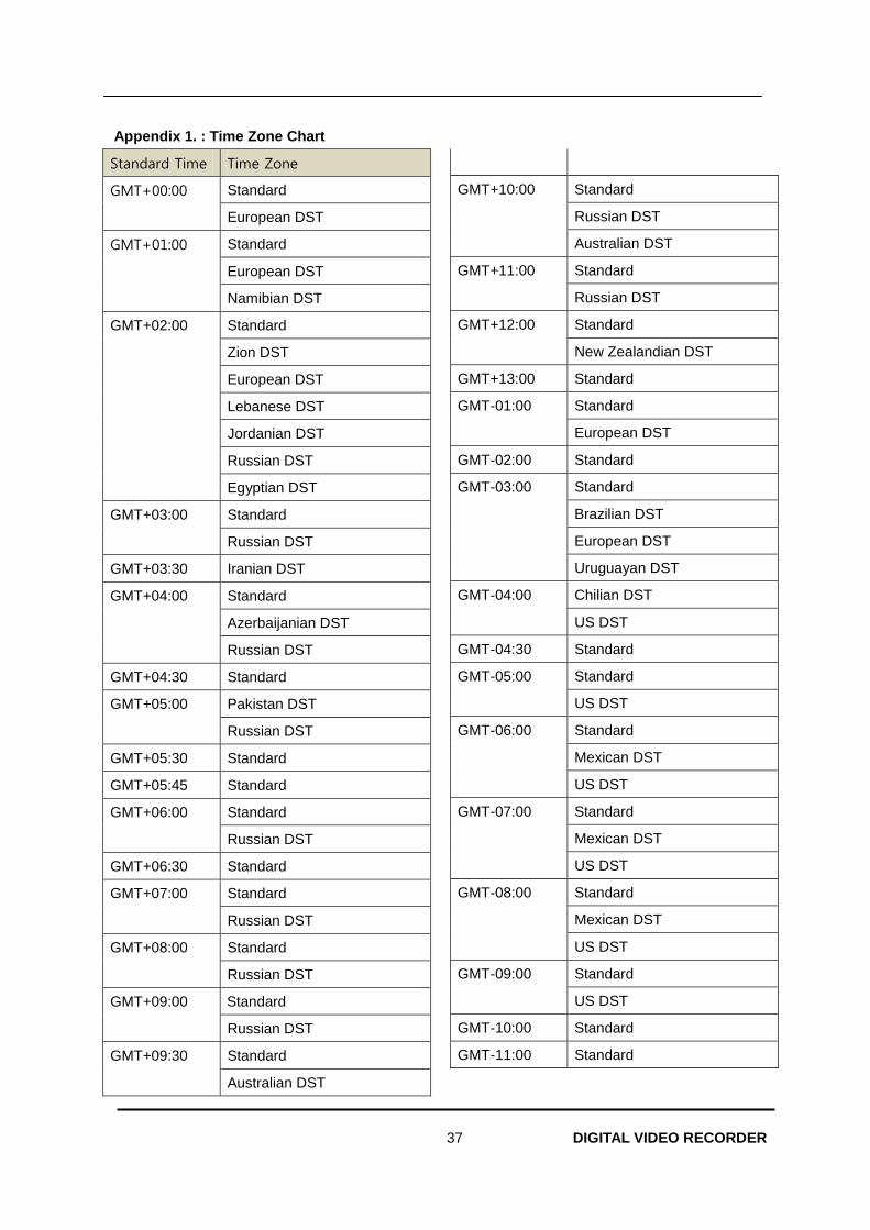
37 DIGITAL VIDEO RECORDER
Appendix 1. : Time Zone Chart
Standard Time Time Zone
GMT+00:00 Standard
European DST
GMT+01:00 Standard
European DST
Namibian DST
GMT+02:00 Standard
Zion DST
European DST
Lebanese DST
Jordanian DST
Russian DST
Egyptian DST
GMT+03:00 Standard
Russian DST
GMT+03:30 Iranian DST
GMT+04:00 Standard
Azerbaijanian DST
Russian DST
GMT+04:30 Standard
GMT+05:00 Pakistan DST
Russian DST
GMT+05:30 Standard
GMT+05:45 Standard
GMT+06:00 Standard
Russian DST
GMT+06:30 Standard
GMT+07:00 Standard
Russian DST
GMT+08:00 Standard
Russian DST
GMT+09:00 Standard
Russian DST
GMT+09:30 Standard
Australian DST
GMT+10:00 Standard
Russian DST
Australian DST
GMT+11:00 Standard
Russian DST
GMT+12:00 Standard
New Zealandian DST
GMT+13:00 Standard
GMT-01:00 Standard
European DST
GMT-02:00 Standard
GMT-03:00 Standard
Brazilian DST
European DST
Uruguayan DST
GMT-04:00 Chilian DST
US DST
GMT-04:30 Standard
GMT-05:00 Standard
US DST
GMT-06:00 Standard
Mexican DST
US DST
GMT-07:00 Standard
Mexican DST
US DST
GMT-08:00 Standard
Mexican DST
US DST
GMT-09:00 Standard
US DST
GMT-10:00 Standard
GMT-11:00 Standard
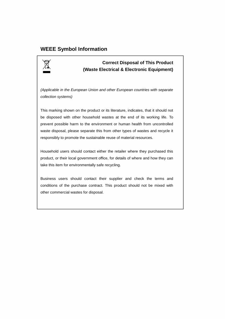
WEEE Symbol Information
Correct Disposal of This Product
(Waste Electrical & Electronic Equipment)
(Applicable in the European Union and other European countries with separate
collection systems)
This marking shown on the product or its literature, indicates, that it should not
be disposed with other household wastes at the end of its working life. To
prevent possible harm to the environment or human health from uncontrolled
waste disposal, please separate this from other types of wastes and recycle it
responsibly to promote the sustainable reuse of material resources.
Household users should contact either the retailer where they purchased this
product, or their local government office, for details of where and how they can
take this item for environmentally safe recycling.
Business users should contact their supplier and check the terms and
conditions of the purchase contract. This product should not be mixed with
other commercial wastes for disposal.

1 DIGITAL VIDEO RECORDER
<Memo>