Embed Size (px)
Citation preview

Digital Profile Radiography – Practical uses and limitations
Mr. Neil Young Asset Reliability Inspections Bunbury, Australia www.ari.com.au [email protected]
AOG 2017 Knowledge Forum Workshop
Introduction
Profile digital radiography for online piping thinning assessment has been in use in Australia since 2005 and recently is gaining significantly more acceptance/use.
Today all major refineries in Australia use digital imaging for pipe inspection.
This is helped by new international standards.
This workshop aims to explain the uses and limitations of this technology with some real world samples.
AOG 2017 Knowledge Forum Workshop

Digital Radiography – What is it? Essentially the same as conventional film radiography with the exception that the image is captured via reusable digital media instead of film, at a lower radiation dose by either a Digital Detectors Array (DDA) panel or on a Phosphor Imaging Plate (PIP or IP).
Industry separates the two mediums by calling DDA – Digital Radiography (DR) and IP – Computed Radiography (CR).
AOG 2017 Knowledge Forum Workshop

Advantages / Disadvantages
AOG 2017 Knowledge Forum Workshop
• Instant results (DDA) – no reshoots • Fast results (CR) – easy onsite processing
• Software for wall thickness evaluation • Easily shared (email an image) • No chemical dark rooms • Broader area (you get the bigger picture)
• Higher dynamic range • Higher productivity & automated
workflows • Ability to “hunt” degradation
• High initial capital costs • Restricted to smaller size pipes • Additional training • Radiation exclusion zones • Digital, poor data in = poor data out • DDA lower spatial resolution than film

Methods of test - Standards • BS EN 16407-1 Non-destructive testing – Radiographic inspection of
corrosion and deposits in pipes X- and gamma rays Part 1: Tangential radiographic inspection
• BS EN 16407-2 Non-destructive testing — Radiographic inspection of corrosion and deposits in pipes by X- and gamma rays Part 2: Double wall radiographic inspection
AOG 2017 Knowledge Forum Workshop

Pipe Size Limitations (what is readily achievable)
You are restricted on what pipe size / schedule you can test. This restriction is due to the different penetrating power of the radiation type used which is referred to a Wmax in EN16407.1 (referred to as chord length in conventional Australian standards)
AOG 2017 Knowledge Forum Workshop

Standard prescribes maximum allowable thickness (Wmax)
for different types of radiation (different penetrating power)
AOG 2017 Knowledge Forum Workshop
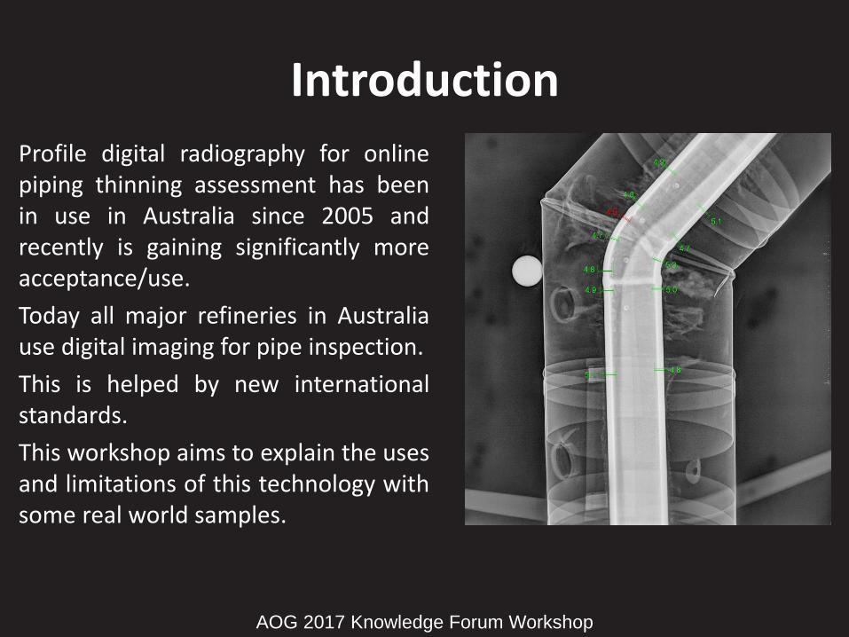
What does this equate to for two commonly used gamma sources?
What does this mean? • Using Se75 for smaller exclusion zones etc gives you less scope than Ir192
• Both sources are only useable on smaller piping
• If using battery powered pulsed X-ray units again for exclusion zones/safety you are more restricted again than when using Se75
• Larger pipes need to be examined with ultrasonic or eddy current techniques
TIP: Fittings are thicker so if you have designed a PRT scope on the upper limits based on pipe size/schedule you will struggle for accurate data on the fittings (elbows, Tees etc) attached to these pipes [which is typically where you are looking with flow/direction changes]
AOG 2017 Knowledge Forum Workshop
Ir192 Se75
Sch40 Sch80 Sch160 Sch40 Sch80 Sch160
DN 15-65 Yes Yes Yes Yes Yes Yes
DN 80 Yes Yes Yes Yes Yes No
DN 90 Yes Yes N/A Yes Yes N/A
DN 100 Yes Yes No No No No
DN 125 Yes Yes No No No No
DN 150 Yes Yes No No No No
DN 200 No No No No No No

Insulation – Internal and External pipe degradation
A key advantage of this technology is that by looking at the image you detect internal (flow/contents) degradation and/or external corrosion (CUI)
If you detect CUI at early stages you can then address the issue/s with a repair before costly replacements
EN16407-01 Standard prescribes a visual assessment of the area as well by stating on the test report the “condition of the insulation”
• No point in getting a satisfactory radiographic result and not being advised of degradation of the insulation that will affect the result at the next inspection
• With the right service provider you can get a visual examination of the lagging and the thickness result
• Our reports detail this and include a set up image which can double as record of condition of the recording point at time of test
AOG 2017 Knowledge Forum Workshop

AOG 2017 Knowledge Forum Workshop

Order of Accuracy – Set up mistakes • Image Calibration – Test arrangement OR Reference Object
• Understand where you want to test – intrados/extrados, washout, flow/impact
AOG 2017 Knowledge Forum Workshop

Tangential Offset - Ensure you are “square” with the wall you are trying to examine
Detector
Misalignment
Pipe Misalignment
Source Placement
Larger pipes don’t then go “measuring” the other side
AOG 2017 Knowledge Forum Workshop

Tangential Centerline - Ensure your source is central and your comparator ball is offset to correctly capture the enlargement (examine both sides)
AOG 2017 Knowledge Forum Workshop
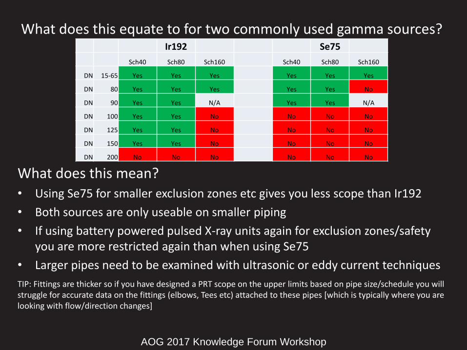
Reducing The Human Factor • All previous sources of error are human and are reducible
• Ask for ISO9712 certification such as that offered by the AINDT
• Ask for specific ISO17025 accreditation offered by NATA
AOG 2017 Knowledge Forum Workshop

Sample Images Wrapped Temporary Repair Pipe Test
AOG 2017 Knowledge Forum Workshop

Sample Images Soil Air Interface – External Corrosion Blisters
AOG 2017 Knowledge Forum Workshop

Sample Images Bigger Picture
AOG 2017 Knowledge Forum Workshop

Sample Images Wire Rope Trials
AOG 2017 Knowledge Forum Workshop

Software Demonstration • Fittings are thicker
• Upper limit struggles
• Oxide separation wall thickness tool
• Holed
• Tangential offset opposite calibration side variations
AOG 2017 Knowledge Forum Workshop