Embed Size (px)
Citation preview

Overview of product range206 General overview
Product selection guide208 By functions - by applications
Info & advice216 “Keeping up with current changes”
Instantaneous monostable relays218 POK - RI - OK - F-OK - RE ranges
Time-delay relays236 OK Tm-F - OKTa/Tr/Tt - F-OK T BAO/T BOR ranges
Function relays246 OKCL range
Sockets248 POK - OK - F-OK - RI - RE ranges
CONTROLLINGAND RELAYS
3
4
5
6
ENER
GY M
ETER
S PO
WER
MON
ITORS
ANAL
OGUE
PA
NEL
METE
RSDIGITA
L PA
NEL
METE
RSTR
ANSD
UCER
SAN
D RE
CORD
ERS
TRAN
SFOR
MERS
SHUN
TSCO
NTRO
LLING
AND
RELA
YS
7
APPE
NDIX
2
1
204205

226
OK range
222
RI range
Gene
ral o
vervi
ewCo
ntrollin
g an
d relay
s CONTROLLING AND RELAYS
Instantaneous monostable relays
218
POK range
232
RE range
230
F-OK B
Time-delay relays
236
OK Tm-F range
240
OK Ta/Tr/Tt range
244
F-OKTBAO/TBOR range
Selecting a product
?208
Selecting a product
?210

256
Sockets forthe RE range
208216
SELECTION GUIDEINFO & ADVICE
Sockets
248
Sockets forthe POK rangethe OK rangethe F-OK range
Sockets forthe RI range
Function relays
246
OK CLflashing relay
Customized productsConsult us
Other function relays
254
206207
Selecting a product
?212
3
4
5
6
ENER
GY M
ETER
S PO
WER
MON
ITORS
ANAL
OGUE
PA
NEL
METE
RSDIGITA
L PA
NEL
METE
RSTR
ANSD
UCER
SAN
D RE
CORD
ERS
TRAN
SFOR
MERS
SHUN
TSCO
NTRO
LLING
AND
RELA
YS
7
APPE
NDIX
2
1

5 A
2 4 6 3 5
2.2 2.7 3.2
Prod
uct selec
tion
guide
Controllin
g an
d relay
s SELECTING AN INSTANTANEOUS MONOSTABLE
218
POK range
Breaking capacity adapted to inductive loads.Magnetic blow-out as standard. Independent cut-offchambers.
High-performance models for inductive loads. Directmounting option (without socket). Compact design.
5 A
AgCd
2
7 A
0.8 to 1.1 Un 0.8 to 1.2 Un
2
0.85 to 1.1 Un
3
0.85 to 1.1 Un
3.8 5.8
AgCu3
RI range
222
POK BiPOK TriPOK RI 270 RI 370 RI 550Model
Instantaneous contacts
Nominal thermal current
Number of RT
contacts T
Type of contacts
DC Coil controlled
6 V12 V24 V26 V28 V30 V36 V48 V
Direct voltage 60 V72 V100 V110 V125 V127 V200 V220 V250 V550 V
Operating range
Consumption (W)
AC Coil controlled
6 V12 V24 V48 V100√3 V60 V
AC voltage 110 V110√3 V127 V220 V415√3 V240 V380 V
Operating range
Consumption (VA)
Advantages

0.8 to 1.2 Un 0.85 to 1.1 Un
5
50 to 90 V
3
4
0.7 to 1.25 Un
206216
GENERAL OVERVIEWINFO & ADVICE
208209
< 5 VA
0.8 to 1.1 Un
AgCdO10
4
0.8 to 1.3 Un
Ag
0.8 to 1.1 Un
3.5 < 4.1 < 5
4
RELAY
232226 230
OK range RE rangeF-OK B
Robustness. High reliability for intensive use in severe conditions. Strong contacts when inoperation. Breaking power adapted to inductive charges.
High reliabilityfor intensiveuse in severec o n d i t i o n s .Rail approved.
High reliability for intensive use in severeconditions. Breaking power adapted toinductive charges.
10 A
4 4 double-breakcontacts
Ag AgCd AgCd
10 A 10 A
4
10 A
0.85 to 1.1 Un
4
0.8 to 1.1 Un
4.5
3
0.8 to 1.1 Un
< 3
0.8 to 1.1 Un
6
OK N OK Fc OK-B184 OK SCd OK SGc Cd OK SFc UIC F-OK B RE3000 RE3000S RE3000N
5
0.8 to 1.1 Un
3
4
5
6
ENER
GY M
ETER
S PO
WER
MON
ITORS
ANAL
OGUE
PA
NEL
METE
RSDIGITA
L PA
NEL
METE
RSTR
ANSD
UCER
SAN
D RE
CORD
ERS
TRAN
SFOR
MERS
SHUN
TSCO
NTRO
LLING
AND
RELA
YS
7
APPE
NDIX
2
1

2 4
2 2
2 4
Prod
uct selec
tion
guide
Controllin
g an
d relay
s SELECTING A TIME-DELAY RELAY
236
OK Tm-F range
1 s to 9h06
0.8 to 1.15 Un
4 W
Ag
5 A
0.8 to 1.15 Un
4 VA
Time-delay duration adjustable over wide range.Magnetic blow-out. Mixed contact models: time-delay and instantaneous.
Time-delay duration adjustable over wide range.Magnetic blow-out.
OK Tm-F 2E OK Tm-F 2R OK Tm-F 4E OK Tm-F 4RModel
Contacts
Nominal thermal current
Time delay RT at make
contacts RT at break
Instantaneous RT
contacts T
Type of contacts
Time delay range
Adjustable using switch
Adjustable using potentiometer
Adjustment range
DC Coil controlled
12 V
24 V
48 V
60 V
Direct voltage 72 V
100 V
110 V
125 V
220 V
230 V
Operating range
Consumption
AC Coil controlled
24 V
48 V
60 V
110 V
125 V
127 V
220 V
230 V
Operating range
Consumption
Advantages

206216
GENERAL OVERVIEWINFO & ADVICE
210211
4 1 1
2 1
3 1
0.5 to 40 s0.5 to 40 s
OK Ta/Tr/Tt range F-OK range
240 244
0.85 to 1.1 Un 50 to 90 Vdc
4 W 4.5 W
0.85 to 1.1 Un
4 VA 5 VA
Time-delay duration adjustable over fixed range.Magnetic blow-out.
Time-delay duration adjustable over fixed range.Magnetic blow-out. Mixed contact models: time-delay and instantaneous.
Time-delay relay F-OK B
5 A 0.8 A - 0.25 A
1
Ag
5, 15, 60 or 180 s 4, 14, 50 or 180 s
0.1 to 1 Tn (nominal time) 0.1 to 1 Tn
OK Ta "make" OK Tr "break" OK Tt "make" OK Tt "break" F-OK TBAO F-OK TBOR
3
4
5
6
ENER
GY M
ETER
S PO
WER
MON
ITORS
ANAL
OGUE
PA
NEL
METE
RSDIGITA
L PA
NEL
METE
RSTR
ANSD
UCER
SAN
D RE
CORD
ERS
TRAN
SFOR
MERS
SHUN
TSCO
NTRO
LLING
AND
RELA
YS
7
APPE
NDIX
2
1

Prod
uct selec
tion
guide
Controllin
g an
d relay
s SELECTING A RELAY SOCKET
Depending on the number of contacts available onthe socket, it is possible to position one or moreidentical or complementary relays.
For example:The 78BF socket gets 24 contacts and can receive:
- 3 POK relays (8) - 1 POK relay (8) and 1 BiPOK relay (16)- 1 TriPOK relay (24)- 1 POK relay (8) and 1 OK relay (16)
: double-: without spring
: with strap+: spring included
DIN rail mounting(optional)
Relay sockets POK / OK / F-OK
Rear socket
RPB43 RPB48
RC43 RC43 RC43 RC48
RL43 RL43
No. 85 No. 85
RL43 RL48
RPB43 RPB43- -
RPB43 RPB43 -
+
RC43 RC43 RC43 RC48
RC43 RC43
No. 85 No. 85
RC43 RC48
+
RPB43 RPB48
RPB43 RPB43 RPB48
- -
Sockets
Number of contacts 8 16 24 8 16 24 2x16 16 16 16 16 16 8 16 24
screw contact
blade contact
soldering lug
printed circuit
Compatibility with instantaneous relays + locking spring
POK
POK range BiPOK
TriPOK
OK rangeshort cover
long cover
F-OK range F-OK B
RE range
RI 270
RI range RI 370
RI 550
Compatibility with time delay relays + locking spring
OK rangeTm-F
Ta/Tr/Tt
F-OK range TBAO/TBOR
Advantages
Protection rating IP 20
Compliance with standards NF-F 16-101, NF-F 16-102
53F 43F 73F 54F 43DF 74F 47N 55 84F 63A 56 65F 50BF 48BF 78BF
Front

206216
GENERAL OVERVIEWINFO & ADVICE
DIN rail mounting(optional)
High-performance versionRL/RI
212213
Rear socket Rear socketFront socket Frontsocket
256 254
RE Relay socket RI Relay socket
248
RPB48
RC48 RC43
RL48 RL43
RPB43RPB48
+
RC48 RC43
RC48 RC43
+
RPB48
RC/RI RC/RI RC/RI
RC/RI RC/RI RC/RI
RC/RI RC/RI RC/RI
RPB43
8 16 24 16 16 14 14 14 14 14 11 17 11 17 11 17
51F 48F 78F 68A 68C ERV 310 ERL 310 ERL 320 EVV 3100 EVL 3100 111 171 112 172 110 170
socket
3
4
5
6
ENER
GY M
ETER
S PO
WER
MON
ITORS
ANAL
OGUE
PA
NEL
METE
RSDIGITA
L PA
NEL
METE
RSTR
ANSD
UCER
SAN
D RE
CORD
ERS
TRAN
SFOR
MERS
SHUN
TSCO
NTRO
LLING
AND
RELA
YS
7
APPE
NDIX
2
1

Notes
& com
mentsCo
ntrollin
g an
d relay
s

216218
INFO & ADVICERANGE INFO
214215
OK B 184relay
OK Tt “Make”relays
F-OK TBOR"Break"
time delay
OK CIFlashing
relay
3
4
5
6
ENER
GY M
ETER
S PO
WER
MON
ITORS
ANAL
OGUE
PA
NEL
METE
RSDIGITA
L PA
NEL
METE
RSTR
ANSD
UCER
SAN
D RE
CORD
ERS
TRAN
SFOR
MERS
SHUN
TSCO
NTRO
LLING
AND
RELA
YS
7
APPE
NDIX
2
1

Info
& ad
viceCo
ntrollin
g an
d relay
s KEEPING UP WITH CURR A U T O M A T I C R E L A Y S Y S T E M S
A relay is subject to varying levels of wear, depending on the conditions in which it is used.To avoid replacing it too often, it is best to carefully evaluate the selection criteria
In automatic systems, relays and displacement sensors are componentsof vital importance. It is therefore necessary to evaluate carefully thecriteria guiding your choice.
CHOOSING THE MOST SUITABLE RELAY:10 SELECTION CRITERIA
Electromagnetic efficiencyThis represents the relationship between the magneticflux generated by the coil of the relay and theresulting mechanical energy that operates the contact.The greater the electromagnetic efficiency the moreaccurate the relay.
Breaking capacityA relay should be capable of breaking both low-energycircuits and high-energy circuits, without generating aparasite electrical arc.
Relay ratingThis is calculated by taking 130 % of the maximumcurrent and adding the transitory overloads.
Number and type of contactsInverters (changeover), NO (normally open), NC (normally closed), instantaneous, time delay, etc.
Contact kinematicsThis is, in reality, the pressure exerted on the relaycontacts, and is an indicator of the resistance of therelay to shocks and vibrations.
Life curveThe number of mechanical and electrical operations"guaranteed error free" (depends on the switchedpower).
Response timeThis is expressed in milliseconds (ms).
Supply voltage and operating rangeThis determines the operating limits of the relayaccording to supply and temperature threshold limits.
Break voltageThis is the voltage below which the return of thecontact to the break state is certified (limitation ofresidual voltage).
Permitted ripple rate (DC)Defines the ripple threshold for which no "bounce" ofthe contact is possible. Such bounces, when they occur,greatly reduce the life curve of the relay.
1
2
3
4
5
6
7
8
9
10

ENT CHANGES...
206208
GENERAL OVERVIEWSELECTION GUIDE
HOW THE RELAYWORKS ?The current flowing through the relay coilgenerates a magnetic flux that flows mostlythrough the coil yoke. The latter is equippedwith an armature, or "keeper", on which thecoil exerts an attractive force of variablestrength, used to open or close one or morecontacts. The know-how and expertise of themanufacturer allows it to exploit this phenomenon so as to optimise the electro-magnetic efficiency and convert the flux intoan attractive force, using the resultingmechanical energy to operate the contacts.The contacts are automatically recalled whenthe electrical excitation has disappeared.
THE ENVIRONMENTTo create an efficient relay, it is necessary to takeinto account the operating and environmentalconstraints affecting the context in which the relaywill be used. These may be chemical, metallurgicalor thermal, and are subject to strict standards(Fire - Emissions - Toxicity). Temperature resistance Fireproofing Resistance to corrosive gases Resistance to shock Resistance to vibrations Dustproofing Contact materials Type of magnetic circuit Surface treatments and finishingRelays have a wide range of applications. ENERDIS candevelop relays to meet your specific constraints andrequirements. Contact us for further information.
“It is important to anticipate operating
environment constraintswhich the relay
will have to respondto in the future
(system upgrades, etc.).”
The RelayHow does the relay's magneticblow-out function?
Everyone knows that one of the main characteristics of arelay is its breaking capacity. In other words, its capacityto cut off a current without the current continuing topropagate in the air (electric arc). However, the maximumbreaking capacity of a relay is dependent on the distancebetween its fixed and mobile contacts. To reduce this, andto limit the dimensions of the relay, magnetic blow-out issometimes added. This is based on a simple idea whichconsists in fitting the relay with a permanent magnet whosemagnetic field is perpendicular to the direction in whichthe contacts open. Under the action of Laplace forces, thearc created at the opening of the contacts lengthens andcools, finally breaking (this is the "blow-out" effect). Thebreaking capacity in direct current is therefore tenfold,enabling the size of the relay to be reduced.
TEST YOUR KNOWLEDGE
FOCUS
Magnetic blow-out enables you to:
Reduce the size of relaysMultiply the breaking capacity by 10Reduce electric arc
What material is normally used for relay contacts?
Silver Stainless steelBronze GoldTin Titanium
To check your answers visit our site:www.enerdis.fr.
216217
3
4
5
6
ENER
GY M
ETER
S PO
WER
MON
ITORS
ANAL
OGUE
PA
NEL
METE
RSDIGITA
L PA
NEL
METE
RSTR
ANSD
UCER
SAN
D RE
CORD
ERS
TRAN
SFOR
MERS
SHUN
TSCO
NTRO
LLING
AND
RELA
YS
7
APPE
NDIX
2
1

Independentinterrupter tubefor each contact
Output via Fastonlug connectors(5 x 0.8 mm)
Instantan
eous m
onostable
rela
ysCo
ntrollin
g an
d relay
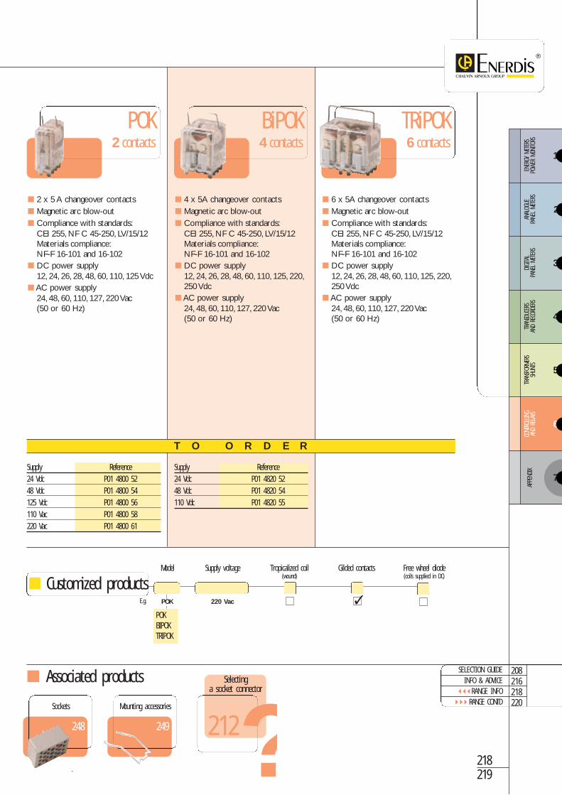
s POK RANGEPlug-in 5 A relays with 2, 4 or 6 inverter contacts andindependent interrupter tubes
The POK, BiPOK and TriPOK plug-in relays constitute a modular range, of which thePOK represents the basic standard model. This enables you to adapt the number ofcontacts as closely as possible to their required use, thus reducing cabling time andconsumption.
Description
Dimensions (in mm)
POK
BiPOK
PRODUCT ADVANTAGES
BREAKING CAPACITY ADAPTED to inductive loads
MAGNETIC BLOW-OUT as standard
CONTACTS available in a wide choice of materials
5020
4510
588
20 POK
40 BiPOK
60 TriPOK
TRiPOK
SELECTION GUIDEINFO & ADVICE
RANGE INFO RANGE CONTD
208216218220
Associated products
Supply Reference24 Vdc P01 4800 5248 Vdc P01 4800 54125 Vdc P01 4800 56110 Vac P01 4800 58220 Vac P01 4800 61
Supply Reference24 Vdc P01 4820 5248 Vdc P01 4820 54110 Vdc P01 4820 55
2 x 5 A changeover contacts Magnetic arc blow-out Compliance with standards:
CEI 255, NF C 45-250, LV/15/12Materials compliance:NF-F 16-101 and 16-102
DC power supply 12, 24, 26, 28, 48, 60, 110, 125 Vdc
AC power supply 24, 48, 60, 110, 127, 220 Vac (50 or 60 Hz)
4 x 5A changeover contacts Magnetic arc blow-out Compliance with standards:
CEI 255, NF C 45-250, LV/15/12Materials compliance:NF-F 16-101 and 16-102
DC power supply 12, 24, 26, 28, 48, 60, 110, 125, 220,250 Vdc
AC power supply 24, 48, 60, 110, 127, 220 Vac (50 or 60 Hz)
POK2 contacts
BiPOK4 contacts
6 x 5A changeover contacts Magnetic arc blow-out Compliance with standards:
CEI 255, NF C 45-250, LV/15/12Materials compliance:NF-F 16-101 and 16-102
DC power supply 12, 24, 26, 28, 48, 60, 110, 125, 220,250 Vdc
AC power supply 24, 48, 60, 110, 127, 220 Vac (50 or 60 Hz)
TRiPOK6 contacts
T O O R D E R
POKBIPOKTRIPOK
Model Supply voltage Tropicalized coil Gilded contacts Free wheel diode(wound) (coils supplied in DC)
POK 220 Vac
Customized products
218219
248
Sockets
249
Mounting accessories
Selectinga socket connector
?212
E.g.
3
4
5
6
ENER
GY M
ETER
S PO
WER
MON
ITORS
ANAL
OGUE
PA
NEL
METE
RSDIGITA
L PA
NEL
METE
RSTR
ANSD
UCER
SAN
D RE
CORD
ERS
TRAN
SFOR
MERS
SHUN
TSCO
NTRO
LLING
AND
RELA
YS
7
APPE
NDIX
2
1

Instantan
eous m
onostable
rela
ysCo
ntrollin
g an
d relay
s POK RANGE
General characteristics
Electrical specifications
Dielectric strength:Coil/contacts: 2,000 V - 50 Hz - 1 minuteContact/contact: 1,000 V - 50 Hz - 1 minuteInsulation resistance: under 500 Vdc as per EN 61810: > 1,000 MΩMechanical life cycle: 20 x 106 operationEnvironment:Operating temperature: -10 °C to +55 °CStorage temperature: -40 °C to +85 °CRelative humidity: standard version: < 80 %
Tropicalised version: = 95 %Resistance to vibrations: 5 g - 5 to 60 Hz - 1 minute as per EN 61810Resistance to shocks: 20 g - 11 ms - 1/2 sine as per EN 61810Protection rating: IP 40Compliance with standards: EN 61810, Materials compliance NF-F 16-101, NF-F 16-102 and IEC 95-2-1
Plug-in relays with 2, 4 or 6 changeover contacts (5 A) and independent interrupter tubes
POK BiPOK TriPOKModelDC coil supply
Nominal voltage (Un) 12 24 26 28 48 12 24 26 28 48 12 24 26 28 4860 110 125 Vdc 60 110 125 220 250 Vdc 60 110 125 220 250 Vdc
Operating range (from -10 °C to +55 °C) 0.8 to 1.1Un 0.8 to 1.1 Un 0.8 to 1.1 Un
Consumption 2.2 W 2.7 W 3.2 W
Break voltage 0.2 Un 0.2 Un 0.2 Un
AC coil supply
Nominal voltage (Un) 24 48 24 48 24 48 60 110 127 220 Vac 60 110 127 220 Vac 60 110 127 220 Vac
Operating range (from -10 °C to +55 °C) 0.85 to 1.1 Un 0.85 to 1.1 Un 0.85 to 1.1 Un
Consumption 3.8 VA 3.8 VA 5.8 VA
Break voltage > 0.1 Un > 0.1 Un > 0.1 Un
Instantaneous changeover contactsNumber 2 RT 4 RT 6 RT
Nominal thermal current 5 A 5 A 5 A
Type AgCu3 AgCu3 AgCu3
Maximum operating voltage 250 Vdc or 300 Vac 250 Vdc or 300 Vac 250 Vdc or 300 Vac
Maximum intermittent current 100 A during 10 ms 100 A during 10 ms 100 A during 10 ms
Pressure of make contact 0.5 N 0.5 N 0.5 N
Pressure of break contact > 0.2 N > 0.2 N > 0.2 N
Make time DC ″ 30 ms ″ 30 ms ″ 30 ms
Make/break AC ″ 35 ms ″ 35 ms ″ 35 ms
Break time DC ″ 25 ms ″ 25 ms ″ 25 ms
Make/break AC ″ 40 ms ″ 40 ms ″ 40 ms
Weight 0.09 kg 0.170 kg 0.240 kg

BiPOKPOK
TriPOK
1
2 3 6
5 4 8 7
1B
2B 3A 6A
5A 4A 8A 7A
3B 6B
5B 4B 8B 7B
3C 6C
5C 4C 8C 7C
Electrical connections
DC breaking capacity AC breaking capacity
A - 24 V, L/R = 0B - 48 V, L/R = 0C - 24 V, L/R = 40 ms
D - 48 V, L/R = 40 msE - 72 V, L/R = 20 msF - 110 V, L/R = 10 ms
A - 48 V, 50 Hz, cos ϕ = 1B - 110 V, 50 Hz, cos ϕ = 1C - 110 V, 50 Hz, cos ϕ = 0.7
D - 220V, 50 Hz, cos ϕ = 1E - 220 V, 50 Hz, cos ϕ = 0.7F - 440 V, 50 Hz, cos ϕ = 1
1A
2B 3A 6A
5A 4A 8A 7A
3B 6B
5B 4B 8B 7B
220221
208216218
SELECTION GUIDEINFO & ADVICE
RANGE INFO
3
4
5
6
ENER
GY M
ETER
S PO
WER
MON
ITORS
ANAL
OGUE
PA
NEL
METE
RSDIGITA
L PA
NEL
METE
RSTR
ANSD
UCER
SAN
D RE
CORD
ERS
TRAN
SFOR
MERS
SHUN
TSCO
NTRO
LLING
AND
RELA
YS
7
APPE
NDIX
2
1

Instantan
eous m
onostable
rela
ysCo
ntrollin
g an
d relay
s
RI 270
RI RANGEPlug-in relays with 2, 3 or 5 changeover contacts,5 or 7 A, with compact design
The high-stroke models, with or without blow-out, are specially designed for theswitching of high loads: they facilitate the break of the electric arc when the contactsare open.
For switching mid-sized loads (highly resistant to erosion) and to ensure protectionof contacts, relays equipped with gilded contacts are recommended.The inalterableand rust-resistant qualities of gold available on these models ensures long-termhighly-resistant relay contacts.
Direct or panelmounting (option):connection via lugconnectors on relay
Output connectors:Faston lugs2.8 x 0.5 mm
Description
PRODUCT ADVANTAGES
RI 270 and RI 370 HIGH STROKE MODELS for inductive loads
RI 270 HIGH STROKE MODEL with magnetic blow-out option
DIRECT PANEL MOUNTING option (without socket)
RI 370
RI 550
Dimensions (in mm)Relay RI 270 and RI 370 Relay RI 550
3148 (standard)
55 (high-stroke version) 47 50
36 36

Associated products
2 x 7 A changeover contacts High stroke for inductive load Magnetic blow-out option DC power supply
6, 12, 24, 48, 110, 125, 220 Vdc AC power supply
6, 12, 24, 48, 110, 127, 220, 380 Vac
3 x 7 A changeover contacts High stroke for inductive load DC power supply
6, 12, 24, 48, 110, 125, 220 Vdc AC power supply
6, 12, 24, 48, 110, 127, 220, 380 Vac
5 x 5 A changeover contacts DC power supply
6, 12, 24, 48, 110, 125, 220 Vdc AC power supply
6, 12, 24, 48, 110, 127, 220, 380 Vac
RI 2702 contacts
Supply Reference24 Vdc P01 4470 0148 Vdc P01 4470 0248 Vac P01 4470 03110 Vac P01 4470 04220 Vac P01 4470 05
Supply Reference24 Vdc P01 4470 1148 Vdc P01 4470 1248 Vac P01 4470 13110 Vac P01 4470 14220 Vac P01 4470 15
Supply Reference24 Vdc P01 4470 2148 Vdc P01 4470 2248 Vac P01 4470 23110 Vac P01 4470 24220 Vac P01 4470 25
RI 3703 contacts
RI 5505 contacts
T O O R D E R
254
Sockets
254
Mounting accessories
Supply Direct Gilded High-stroke* Magnetic** Free wheel diodeModel voltage fitting contacts contacts blow-out for DC supply coil
RI 270 220 Vac
*Only for RI 270 RI 370**Only for RI 270 high-stroke
222223
SELECTION GUIDEINFO & ADVICE
RANGE INFO RANGE CONTD
208216222224
Selectinga socket connector
?212
Customized products
E.g.
3
4
5
6
ENER
GY M
ETER
S PO
WER
MON
ITORS
ANAL
OGUE
PA
NEL
METE
RSDIGITA
L PA
NEL
METE
RSTR
ANSD
UCER
SAN
D RE
CORD
ERS
TRAN
SFOR
MERS
SHUN
TSCO
NTRO
LLING
AND
RELA
YS
7
APPE
NDIX
2
1

RI 270 RI 370 RI 550
Instantan
eous m
onostable
rela
ysCo
ntrollin
g an
d relay
s
Electrical specifications
RI RANGEPlug-in relays with 2, 3 or 5 changeover contacts (5 or 7 A), compact design
ModelDC coil supply
Nominal voltage (Un) 6 12 24 48 6 12 24 48 6 12 24 48110 125 220 110 125 220 110 125 220
Operating range (from -10 °C to +55 °C) 0.8 to 1.2 Un 0.8 to 1.2 Un 0.8 to 1.2 Un
Consumption 2 W 2 W 2 W
Break voltage 0.05 Un 0.05 Un 0.05 Un
AC coil supply
Nominal voltage (Un) 6 12 24 48 110 6 12 24 48 110 6 12 24 48 110127 220 380 127 220 380 127 220 380
Operating range 0.85 to 1.1 Un 0.85 to 1.1 Un 0.85 to 1.1 Un
Consumption 3 VA 3 VA 3 VA
Break voltage 0.15 Un 0.15 Un 0.15 Un
Instantaneous changeover contactsNumber 2 RT 3 RT 5 RT
Nominal thermal current 7 A 7 A 5 A
Type AgCd AgCd AgCd
Maximum operating voltage 110 Vdc or 250 Vac 110 Vdc or 250 Vac 110 Vdc or 250 Vac
Maximum intermittent current 50 A during 100 ms 50 A during 100 ms 50 A during 100 ms
Pressure of make contact > 0.5 N > 0.5 N > 0.5 N
Pressure of break contact > 0.2 N > 0.5 N > 0.5 N
Make time DC Standard 22 ms 22 msHigh stroke 24 ms 24 ms
21 ms
Make/break AC Standard 22 ms 22 msHigh stroke 25 ms 26 ms
21 ms
Break time DC Standard 17 ms 19 ms High stroke 38 ms 34 ms
24 ms
Make/break AC Standard 20 ms 20 msHigh stroke 35 ms 28 ms
23 ms
Weight Standard 80 g 80 g 100 gHigh stroke 85 g 85 g
Dielectric strength:Coil/contacts: 2,000 V - 50 Hz - 1 minuteContact/contact: 2,000 V - 50 Hz - 1 minuteInsulation resistance: under 500 Vdc as per EN 61810: > 10,000 ΩMechanical life cycle: 20 x 106 operationsEnvironment:Operating temperature: -25 °C to +55 °CStorage temperature: -25 °C to +70 °CResistance to vibrations: 4 g - 10 to 55 Hz - 1 minute as per IEC 61810Resistance to shocks (energized relay): 20 g - 11 ms - 1/2 sine as per IEC 61810Protection rating: IP 40Compliance with standards: IEC 61810, EN 61810 LV 15/1/2Materials compliance: NF-F 16-101, NF-F 16-102 and IEC 695-2-1
General characteristics

DC breaking capacity
Electrical connections
Standard version(RI 270 – RI 370 – RI 550)
High-stroke version(RI 270 – RI 370)
High-stroke version with magneticblow-out (RI 270)
RI 270 RI 370
RI 550
A: 48 V, L/R = 0 B: 48 V, L/R = 40 ms C: 125 V, L/R = 0 D: 125 V, L/R = 40 ms
AC breaking capacity
Standard version(RI 270 – RI 370 – RI 550)
High-stroke version(RI 270 – RI 370)
High-stroke version with magneticblow-out (RI 270)
A: 24 V, L/R = 0 B: 24 V, L/R = 40 ms C: 220 V, L/R = 0 D: 220 V, L/R = 40 ms
224225
208216222
SELECTION GUIDEINFO & ADVICE
RANGE INFO
3
4
5
6
ENER
GY M
ETER
S PO
WER
MON
ITORS
ANAL
OGUE
PA
NEL
METE
RSDIGITA
L PA
NEL
METE
RSTR
ANSD
UCER
SAN
D RE
CORD
ERS
TRAN
SFOR
MERS
SHUN
TSCO
NTRO
LLING
AND
RELA
YS
7
APPE
NDIX
2
1

Instantan
eous m
onostable
rela
ysCo
ntrollin
g an
d relay
s OK RANGEPlug-in relays with 4 changeover contacts, 10 A,for intensive use in severe environments
Adapted to severe operating constraints, OK relays ensure correct switching opera-tions under strong vibration conditions, thanks to their special contact guiding system.
The materials used to manufacture the relays makes them compliant with standards NFF 16-101, NF F 16-102 (behaviour in fire and toxic fumes) and IEC 695-2-1 (incandes-cent wire test at 850 °C during 30 seconds).
Output connectorsFaston lugs5 x 0.8 mm
Description
Dimensions (in mm)
OK N
OK Fc
OK B 184
OK SCd
PRODUCT ADVANTAGES
HIGHLY RELIABLE for intensive use in severe conditions
HIGH BREAKING CAPACITY CONTACTS thanks to plunger armature coil
BREAKING CAPACITY ADAPTED to inductive loads
OK SGc Cd
OK Sfc UIC
114
10
61,5
42
35
10
74
121
4545
Transparent coverfor permanentcontact statusdisplay

Associated products
4 x 10 A changeover contacts General purpose DC power supply:
12, 24, 28, 48, 110, 125, 220, 250 Vdc AC power supply:
24, 48, 110, 127, 220 Vac(50 or 60 Hz)
4 x 10 A changeover contacts Low consumption DC power supply:
12, 24, 28, 48, 110, 125, 220, 250 Vdc AC power supply:
24, 48, 110, 127, 220 Vac(50 or 60 Hz)
OK NGeneral purpose
OK FcLow consumption
4 x 10 A changeover contacts Low consumption Magnetic arc blow-out
as standard DC power supply:
48 or 125 Vdc
4 x 10 A changeover contacts For lighting circuits - high operating
capacity under heavy loads DC power supply:
12, 24, 48, 110, 125, 220, 250 Vdc AC power supply:
24, 48, 110, 127, 220 Vac
4 x 10 A changeover contacts For high inductive loads DC power supply:
12, 24, 48, 110, 125, 220, 250 Vdc AC power supply:
24, 48, 110, 127, 220 Vac
4 x 10 A changeover contacts For rail applications Magnetic arc blow-out as standard DC power supply:
72 Vdc
OK B 184EDF approval
HN 63/95/125/C
OK SCdAg Cd contacts
OK SGc CdHigh-stroke contacts
OK SFc UICStandard-compliant
UIC 616-0
T O O R D E R
Model Supply Reference
OK B 18448 Vdc P01 4560 16125 Vdc P01 4560 17
OK SFc UIC 72 Vdc P01 4561 93
Supply Tropicalised Gilded Free wheel diode Test Integrated Indicator MagneticModel* voltage coil contacts (DC coil supply) lever lamp light blow-out
(wound) (OK Fc only)
220 Vdc
Customizedproducts
OK NOK FcOK SCdOK SGc Cd
OK Fc
*OK B 184 and OK SFc UIC: only available in standard reference version.
Customized product versions not available
226227
248
Sockets
249
Mounting accessories
SELECTION GUIDEINFO & ADVICE
RANGE INFO RANGE CONTD
208216226228
Selectinga socket connector
?212
E.g.
3
4
5
6
ENER
GY M
ETER
S PO
WER
MON
ITORS
ANAL
OGUE
PA
NEL
METE
RSDIGITA
L PA
NEL
METE
RSTR
ANSD
UCER
SAN
D RE
CORD
ERS
TRAN
SFOR
MERS
SHUN
TSCO
NTRO
LLING
AND
RELA
YS
7
APPE
NDIX
2
1

Instantan
eous m
onostable
rela
ysCo
ntrollin
g an
d relay
s OK RANGE
Electrical specifications
Plug-in relays with 4 changeover contacts (10 A) for intensive use in severe environments
Dielectric strength:Coil/contacts: 2,000 V - 50 Hz - 1 minuteContact/contact: 2,000 V - 50 Hz - 1 minuteInsulation resistance: under 500 Vdc as per EN 61810: > 1,000 MΩResistance to vibrations: 5 g - 5 to 60 Hz - 1 minute as per EN 61810Resistance to shocks (energized relay): 30 g - 11 ms - 1/2 sine asper EN 61810Weight: 300 gProtection rating: IP 20 (IP 40 on demand)Compliance with standards: EN 61810 Materials compliance NF-F 16-101, NF-F 16-102 and CEI 695-2-1
Mechanical life cycle:• OK N: 20 x 106
• OK B 184 and OK SGc: 50 x 106
• OK Fc, OK SCd and OK SGc: 100 x 106
Environment:Storage temperature: -40 °C to +85 °C,Relative humidity: < 80 %Operating temperature:• OK N and OK SCd: -25 °C to +40 °C• OK Fc and OK SGc: -25 °C to +50 °C• OK B 184 and OK SFc: -25 °C to +55 °C
General characteristics
Model OK N OK Fc OK B 184 OK SCd OK SGc Cd 0K SFc UICEDF approval Compliance withCompliance with railway standard
Standards EDF standard UIC 616-0HM 63/95/125/C,class B
DC coil supply12 24 28 12 24 28 48 or 12 24 48 12 24 48
Nominal voltage (Un) 48 110 125 48 110 125 125 Vdc 110 125 220 110 125 220 72 Vdc220 250 Vdc 220 250 Vdc 250 Vdc 250 Vdc
Operating range 0.85 to 1.1 Un 0.8 to 1.3 Un 0.8 to 1.1 Un 0.8 to 1.1 Un 0.8 to 1.1 Un 50 to 80 Vdc(at +40 °C) (at +20 °C) (at +55 °C) (at +20 °C) (at +20 °C) (at +40 °C)
Consumption 4 W 3 W 3.5 W 4.5 W 4.5 W < 4.1 W
Break voltage > 0.1 Un > 0.1 Un > 0.1 Un > 0.1 Un 0.1 Un > 7.2 Vdc
AC coil supply
Nominal voltage (Un) 24 48 110 24 48 110 - 24 48 110 24 48 110 -127 220 Vac 127 220 Vac 127 220 Vac 127 220 Vac
Operating range 0.85 to 1.1 Un 0.85 to 1.2 Un - 0.85 to 1.1 Un 0.85 to 1.2 Un -(from -10 to +40 °C) (at +20 °C) (from -10 to +40 °C) (at +20 °C)
Consumption 5 VA 3 VA - 5 VA 5 VA -
Break voltage > 0.1 Un > 0.1 Un - > 0.1 Un 0.1 Un -
Instantaneous changeover or make contactsNumber 4 RT 4 RT 4 RT 4 RT 4 T 4 RT
Nominal thermal current 10 A 10 A 10 A 10 A 10 A 10 A
Type Ag Ag Ag AgCd AgCd Ag
Maximum operating voltage 350 Vdc 350 Vdc 350 Vdc 350 Vdc 350 Vdc 350 Vdcor 440 Vac or 440 Vac or 440 Vac or 440 Vac or 440 Vac or 440 Vac
Maximum intermittent current 150 A 150 A 150 A 200 A 200 A 150 Aduring 10 ms
Pressure of make contact > 0.8 N > 0.8 N > 0.8 N > 0.8 N > 0.8 N > 0.8 N
Pressure of break contact > 0.3 N > 0.3 N > 0.3 N > 0.3 N - > 0.3 N
Make time DC ″ 30 ms ″ 40 ms ″ 30 ms ″ 30 ms ″ 30 ms ″ 40 ms
Make/break AC ″ 45 ms ″ 40 ms - ″ 45 ms ″ 50 ms -
Make time DC ″ 20 ms ″ 20 ms ″ 20 ms ″ 20 ms - ″ 20 ms
Make/break AC ″ 70 ms ″ 80 ms - ″ 70 ms - -

B4 M1 M2 M3 M4
B1
B4 M1
T1
M2
T2
M3
T3
M4
T4B1
B4
R1
M1
T1 R2
M2
T2 R3
M3
T3 R4
M4
T4
Electrical connections
DC breaking capacity AC breaking capacity
OK N – OK Fc
OK B 184 – OK SFc UIC
OK SCd
OK SGcCd
OK N – OK Fc
OK B 184 – OK SFc UIC
OK SCd
OK SGcCd
OK range except OK SGc Cd OK SGc Cd
228229
208216226
SELECTION GUIDEINFO & ADVICE
RANGE INFO
3
4
5
6
ENER
GY M
ETER
S PO
WER
MON
ITORS
ANAL
OGUE
PA
NEL
METE
RSDIGITA
L PA
NEL
METE
RSTR
ANSD
UCER
SAN
D RE
CORD
ERS
TRAN
SFOR
MERS
SHUN
TSCO
NTRO
LLING
AND
RELA
YS
7
APPE
NDIX
2
1

Instantan
eous m
onostable
rela
ysCo
ntrollin
g an
d relay
s F-OK B RELAYSPlug-in relays with 4 double break changeover contacts,10 A - Railway approved NF-F 62002
The F-OK B instantaneous relay (model 400) is equipped with 4 double breakchangeover contacts in series. It combines performance, robust design and easymounting, making it ideal for applications requiring high safety standards and breakingreliability on mean loads. It is used for rolling or static railway equipment, marine, trans-portation and electrical energy production.
Transparent coverfor permanentcontact statusdisplay
Output connectorsFaston lugs (5 x 0.8 mm)
Easy installationand enhanced safetythanks to a widerange of mountingaccessories
Description
Dimensions (in mm)
F-OK B
PRODUCT ADVANTAGES HIGHLY RELIABLE for intensive use in severe conditions
RAILWAY APPROVED NF-F 62002
4 double breaking CONTACT CIRCUITS
HIGH STROKE contacts
1010
5345
85,5
105
8
45

Associated products
T O O R D E R
Model Supply voltage Winding Coil protection Foolproofing
SingleDouble*
Standardor specific
D1-D2
D3-D4
A1
B1
C1 A2
B2
C2 A3
B3
C3 A4
B4
C4
Coil voltage Safety blank Safety blank Foolproofing recess A recess B220Vac C G24Vdc A G36 Vdc F L48 Vdc D G72 Vdc B G72 Vdc double winding F J110 Vdc F G125 Vdc E G550 Vdc F G
aP
R S
O X
Y P
K L
O X
R
R Y
Y Z
C Y
Y F
1 2 3 4
A
B
b
c
d
Customized products
Dependingon foolproofingpanel
Electrical specifications
General characteristicsDielectric strength:Coil/contacts: 2,550 V - 50 Hz - 1 minuteContact/contact: 1,940 V - 50 Hz - 1 minuteInsulation resistance: under 500 Vdc as per EN 61810: > 1,000 ΩMechanical life cycle: 100 x 106 operationsEnvironment: Operating temperature: -25 °C to +70 °CStorage temperature: -40 °C to +70 °C Relative humidity: < 80 %Resistance to vibrations:2 g - 10 to 120 Hz - 1 minute as per NF-F 62002Resistance to shocks (energized relay) :30 g - 18 ms - 1/2 sine as per NF-F 62002Weight: 0.3 kgProtection rating: IP 40Compliance with standards: NF-F 62002, EN 61810Materials compliance NF-F 16-101, NF-F 16-102 and IEC 695-2-1
Electrical connections
Coil voltage
*72 Vdc double winding.
DC coil supplyNominal voltage (Un) 24 36 48 72 110 125 550 VdcOperating range 0.7 to 1.25 Un (+70 °C)Consumption 4.8 WBreak voltage > 0.1 UnAC coil supplyNominal voltage (Un) 48 127 220 VacOperating range 0.8 to 1.1Un (+70 °C)Consumption 4.8 VABreak voltage > 0.1 UnInstantaneous inverter contactsNumber 4 double break inverter contactsNominal thermal current 10 AType Fixed contacts: AgNiMobile contacts AgCdOMaximum operating voltage 350 Vdc or 400 VacMaximum intermittent current 300 A during 10 msPressure of make contact > 0.3 NPressure of break contact > 0.3 NMake time DC ″ 55 msMake/break AC ″ 55 msBreak time DC ″ 25 msMake/break AC ″ 25 ms
F-OK B 72 Vdc double Standard
DC breaking capacity
230231
248
Sockets
249
Mounting accessories
AC breaking capacity
208216226
SELECTION GUIDEINFO & ADVICE
RANGE INFO
Selecting a socketconnector
?212
E.g.
LEDTransilvaristance
3
4
5
6
ENER
GY M
ETER
S PO
WER
MON
ITORS
ANAL
OGUE
PA
NEL
METE
RSDIGITA
L PA
NEL
METE
RSTR
ANSD
UCER
SAN
D RE
CORD
ERS
TRAN
SFOR
MERS
SHUN
TSCO
NTRO
LLING
AND
RELA
YS
7
APPE
NDIX
2
1

Instantan
eous m
onostable
rela
ysCo
ntrollin
g an
d relay
s RE RANGEPlug-in relays with 4 x 10 A changeover contacts
The RE3000 model is designed for use with automation applications in severeclimatic and electrical conditions.
The RE3000S is equipped with a blow-out magnet affording a longer life curve forcontacts on inductive loads.
The RE3000N model benefits from enhanced test control conditions during manufac-turing for the cleaning and resistance measurement of contacts..
Transparent cover forpermanent display ofcontact status
Output connectorsFaston lugs(5 x 0.8 mm)
Description
PRODUCT ADVANTAGES
HIGHLY RELIABLE for intensive use in severe conditions
BREAKING CAPACITY adapted to inductive loads
EDF-APPROVED in 48 Vdc and 125 Vdc
RE 3000
RE 3000 S
RE 3000 N
Dimensions (in mm)

Customized products
Associated products
4 x 10 A changeover contacts General purpose DC power supply:
30, 60, 100, 200, 220, 250 Vdc AC power supply:
12, 100√3, 60, 110√3, 127, 220,415√3, 240 Vac(50 or 60 Hz)
4 x 10 A changeover contacts Magnetic blow-out of arc as standard DC power supply:
12, 24, 48, 60, 110, 127, 200, 220,250 Vdc
AC power supply:24, 48, 100√3, 60, 110√3, 110, 127,220, 415√3, 240, 380 Vac (50 or 60 Hz)
4 x 10 A changeover contacts K3/SEPTEN certification EDF approval HN 45S25 DC power supply:
12, 24, 48, 60, 110, 127, 200, 220,250 Vdc
AC power supply:24, 48, 100√3, 60, 110√3, 110, 127,220, 415√3, 240, 380 Vac (50 or 60 Hz)
RE3000Standard
DC power supply Reference12 Vdc RE3A 412624 Vdc RE3A 412748 Vdc RE3A 4131110 Vdc RE3A 4133127 Vdc RE3A 4135220 Vdc RE3A 4136
AC power supply Reference24 Vac RE3A 410748 Vac RE3A 4111110 Vac RE3A 4113127 Vac RE3A 4115220 Vac RE3A 4116380 Vac RE3A 4117
RE3000 SMagneticblow-out
RE3000 NEDF approval
T O O R D E R
RE 3000RE 3000 SRE 3000 N
Model Power supply
ExampleRE3000 60 Vdc
232233
256
Sockets
256
Mounting accessories
SELECTION GUIDEINFO & ADVICE
RANGE INFO RANGE CONTD
208216232234
Selecting a socketconnector
?212
E.g.
3
4
5
6
ENER
GY M
ETER
S PO
WER
MON
ITORS
ANAL
OGUE
PA
NEL
METE
RSDIGITA
L PA
NEL
METE
RSTR
ANSD
UCER
SAN
D RE
CORD
ERS
TRAN
SFOR
MERS
SHUN
TSCO
NTRO
LLING
AND
RELA
YS
7
APPE
NDIX
2
1

Instantan
eous m
onostable
rela
ysCo
ntrollin
g an
d relay
s
Electrical specifications
RE RANGEPlug-in relays with 4 changeover contacts (10 A)
ModelsDC coil supply
Nominal voltage (Un) 30 60 100 12 24 48 60 110 12 24 48 60 110 200 220 250 Vdc 127 200 220 250 Vdc 127 200 220 250 Vdc
Operating range 0.8 to 1.1 Un 0.8 to 1.1 Un 0.8 to 1.1 Un
Consumption < 3 W < 3 W < 3 W
Break voltage > 0.15 Un > 0.15 Un > 0.15 Un
AC coil supply12 100√3 60 24 48 100√3 60 24 48 100√3 60
Nominal voltage (Un) 110√3 127 220 110√3 110 127 220 110√3 110 127 220 415√3 240 Vac 415√3 240 380 Vac 415√3 240 380 Vac
Operating range 0.8 to 1.1Un 0.8 to 1.1Un 0.8 to 1.1Un
Consumption 6 VA 6 VA < 6 VA
Break voltage > 0.1 Un > 0.1 Un > 0.1 Un
Instantaneous changeover contactsNumber 4 RT 4 RT 4 RT
Nominal thermal intensity 10 A 10 A 10 A
Type AgCd AgCd AgCd
Maximum operating voltage 250 Vdc or Vac 250 Vdc or Vac 250 Vdc or Vac
Maximum intermittent current 250 A during 30 ms 250 A during 30 ms 250 A during 30 ms
Pressure of make contact ≥ 0.2 N ≥ 0.2 N ≥ 0.2 N
Pressure of break contact ≥ 0.2 N ≥ 0.2 N ≥ 0.2 N
Make time DC ″ 45 ms ″ 45 ms ″ 45 ms
Make/break AC ″ 30 ms ″ 30 ms ″ 30 ms
Break time DC ″ 25 ms ″ 25 ms ″ 25 ms
Make/break AC ″ 65 ms ″ 65 ms ″ 65 ms
RE3000 RE3000S RE3000N
Dielectric strength:Coil/contacts: 2,000 V - 50 Hz - 1 minuteContact/contact: 1,000 V - 50 Hz - 1 minuteInsulation resistance under 500 Vdc as per EN 61810: > 1,000 ΩMechanical life cycle: 20 x 106 operationsEnvironment:Operating temperature: -10 °C to +55 °C / HR ″ 65 %Relative humidity: -25 °C to +70 °CStorage temperature: 5 g - 5 to 60 Hz - 1 minute as per IEC 61810Resistance to vibrations (energized relay): 30 g - 11 ms - 1/2 sine as per IEC61810Weight: 0.2 kgProtection rating: IP 20Compliance with standards: UIC 616-0, EN 61810
General characteristics

Breaking capacity
Electrical connections
DC breaking capacity AC breaking capacity
234235
208216232
SELECTION GUIDEINFO & ADVICE
RANGE INFO
3
4
5
6
ENER
GY M
ETER
S PO
WER
MON
ITORS
ANAL
OGUE
PA
NEL
METE
RSDIGITA
L PA
NEL
METE
RSTR
ANSD
UCER
SAN
D RE
CORD
ERS
TRAN
SFOR
MERS
SHUN
TSCO
NTRO
LLING
AND
RELA
YS
7
APPE
NDIX
2
1

Time-d
elay
relay
sCo
ntrollin
g an
d relay
s OK Tm-F RANGEPlug-in relays with 4 x 5 A changeover contacts, with extended time-delayadjuster switch, for intensive use in severe environments.
The OK Tm-F range of relays enables the user to adjust the time delay over a verywide range, offering the double advantage of on-the-spot time-delay adjustment andeasy storage and maintenance of a universal product.
The OK Tm-F 2E and OK Tm-F 2R models offer the extra advantage of 2 instanta-neous contacts, avoiding the need to add an additional instantaneous relay.
Description
PRODUCT ADVANTAGES
HIGHLY RELIABLE for intensive used in severe conditions
EXTENDED AND ADJUSTABLE TIME-DELAY (from a few seconds to 9 hours)
MIXED CONTACT MODELS: time delay and instantaneous
MAGNETIC BLOW-OUT
OK Tm-F 2E
OK Tm-F 2R
OK Tm-F 4R
OK Tm-F 4ETime-delay adjusterswitch (binary 4-bitswitch). Label holderfor customized userinformation.
Transparent cover forpermanent contactstatus display.
Output Faston lugconnectors (5x0.8 mm)
Dimensions (in mm)

Customized products
Associated products
2 x 5 A changeovercontacts, time-delay at make
2 x 5 A instantaneouschangeover
DC power supply 24, 48, 60, 110, 125,230 Vdc
AC power supply24, 48, 60, 110, 125,230 Vac
2 x 5 A changeovercontacts, time-delay at break
2 x 5 A instantaneouschangeover
DC power supply 24, 48, 60, 110, 125,230 Vdc
AC power supply24, 48, 60, 110, 125,230 Vac
4 x 5 A changeovercontacts, time-delay at make
DC power supply 24, 48,60, 110, 125,230 Vdc
AC power supply24, 48, 60, 110, 125,230 Vac
OK Tm-F 2E“make”
Supply Reference24 Vac P01 4562 2148 Vac P01 4562 2260 Vac P01 4562 23110 Vac P01 4562 24125 Vac P01 4562 25230 Vac P01 4562 2624 Vdc P01 4562 3148 Vdc P01 4562 3260 Vdc P01 4562 33110 Vdc P01 4562 34125 Vdc P01 4562 35230 Vdc P01 4562 36
Supply Reference24 Vac P01 4562 4148 Vac P01 4562 4260 Vac P01 4562 43110 Vac P01 4562 44125 Vac P01 4562 45230 Vac P01 4562 4624 Vdc P01 4562 5148 Vdc P01 4562 5260 Vdc P01 4562 53110 Vdc P01 4562 54125 Vdc P01 4562 55230 Vdc P01 4562 56
Supply Reference24 Vac P01 4562 6148 Vac P01 4562 6260 Vac P01 4562 63110 Vac P01 4562 64125 Vac P01 4562 65230 Vac P01 4562 6624 Vdc P01 4562 7148 Vdc P01 4562 7260 Vdc P01 4562 73110 Vdc P01 4562 74125 Vdc P01 4562 75230 Vdc P01 4562 76
Supply Reference24 Vac P01 4562 8148 Vac P01 4562 8260 Vac P01 4562 83110 Vac P01 4562 84125 Vac P01 4562 85230 Vac P01 4562 8624 Vdc P01 4562 9148 Vdc P01 4562 9260 Vdc P01 4562 93110 Vdc P01 4562 94125 Vdc P01 4562 95230 Vdc P01 4562 96
OK Tm-F 2R“break”
OK Tm-F 4E“make”
T O O R D E R
4 x 5 A changeovercontacts, time-delay at break
DC power supply 24, 48, 60, 110, 125,230 Vdc
AC power supply24, 48, 60, 110, 125,230 Vac
OK Tm-F 4R“break”
Supply Tropicalized coil GildedModel voltage (wound) contacts
OK Tm-F 2E 24 Vac
236237
248
Sockets
249
Mounting accessories
SELECTION GUIDEINFO & ADVICE
RANGE INFO RANGE CONTD
208216236238
Selecting a socketconnector
?212
E.g.
3
4
5
6
ENER
GY M
ETER
S PO
WER
MON
ITORS
ANAL
OGUE
PA
NEL
METE
RSDIGITA
L PA
NEL
METE
RSTR
ANSD
UCER
SAN
D RE
CORD
ERS
TRAN
SFOR
MERS
SHUN
TSCO
NTRO
LLING
AND
RELA
YS
7
APPE
NDIX
2
1

Time
delay
rela
ysCo
ntrollin
g an
d relay
s OK Tm-F RANGEPlug-in relays with 4 changeover contacts (5 A) with switch-adjustable extended time delay.
Electrical specifications
Models OK Tm-F 2E OK Tm-F 4E OK Tm-F 2R OK Tm-F 4RDC coil supplyNominal voltage (Un) 24 48 60 110 125 230 24 48 60 110 125 230
Operating range 0.8 to 1.15 Un (+55 °C) 0.8 to 1.15 Un (+55 °C)
Consumption 4 W 4 W
Break voltage 0.2 Un 0.2 Un
AC coil supplyNominal voltage (Un) 24 48 60 110 125 230 24 48 60 110 125 230
Operating range 0.8 to 1.15 Un (+55 °C) 0.8 to 1.15 Un (+55 °C)
Consumption 4 VA 4 VA
Break voltage 0.2 Un 0.2 Un
Contacts
Number 2 x time-delay RTs 4 x time-delay RTs 2 x time-delay RTs 4 x time-delay RTs2 x instantaneous RTs 2 x instantaneous RTs
Nominal thermal current 5 A 5 A
Type Ag Ag
Maximum operating voltage 250 Vdc or 300 Vac 250 Vdc or 300 Vac
Maximum intermittent current during 10 ms 100 A 100 A
Pressure of make contact 0.5 N 0.5 N
Pressure of break contact > 0.2 N > 0.2 N
Time delayRating (adjustable) from 1s to 9h06 from 1s to 9h06
Accuracy 1 % of t + 0.4 % of T + 20 ms 1 % of t + 0.4 % of T + 20 ms
Resolution 1/256th of T 1/256th of T
Repeatability 0.5 % of t 0.5 % of t
Minimum command pulse 50 ms (t) 50 ms (t)
Reset time 100 ms excited relay 100 ms excited relay
400 ms time-delay mode 400 ms time-delay mode
Sensitivity to power interruptionsInsensitivity to interruptions < 10 ms Insensitivity to interruptions < 10 ms
Dielectric strength:Coil/contacts: 2,000 V - 50 Hz - 1 minuteContact/contact : 1,000 V - 50 Hz - 1 minuteInsulation resistance: under 500 Vdc as per IEC 61810: > 1,000 ΩMechanical life cycle: 20 x 106 operationsEnvironment:Operating temperature: -10 °C to +55 °C Relative humidity: 80 %Storage temperature: -25 °C to +70 °CResistance to vibrations: 5 g - 10 to 55 Hz - 1 minute as per IEC 61810Resistance to shocks (energized relay): 20 g - 11 ms - 1/2 sine as per IEC 61810Weight : 270 gProtection rating: IP 40Compliance with standards: EN 61810, Materials compliance NF-F 16-101,NF-F 16-102 and IEC 695-2-1
General characteristics

OK Tm 2R OK Tm 4R
Electrical connections
Operation
AC breaking capacity DC breaking capacity
OK Tm 2E OK Tm 4E
A - 48 V, 50 Hz, cos ϕ = 1B - 110 V, 50 Hz, cos ϕ = 1C - 110 V, 50 Hz, cos ϕ = 0.7
D - 220 V, 50 Hz, cos ϕ = 1E - 220 V, 50 Hz, cos ϕ = 0.7F - 440 V, 50 Hz, cos ϕ = 1
OK Tm-F 2E / OK Tm-F 4E OK Tm-F 2R / OK Tm-F 4R
A - 24 V, L/R = 0B - 48 V, L/R = 0C - 24 V, L/R = 40 ms
D - 48 V, L/R = 40 msE - 72 V, L/R = 20 msF - 110 V, L/R = 10 ms
238239
208216236
SELECTION GUIDEINFO & ADVICE
RANGE INFO
3
4
5
6
ENER
GY M
ETER
S PO
WER
MON
ITORS
ANAL
OGUE
PA
NEL
METE
RSDIGITA
L PA
NEL
METE
RSTR
ANSD
UCER
SAN
D RE
CORD
ERS
TRAN
SFOR
MERS
SHUN
TSCO
NTRO
LLING
AND
RELA
YS
7
APPE
NDIX
2
1

Time
delay
rela
ysCo
ntrollin
g an
d relay
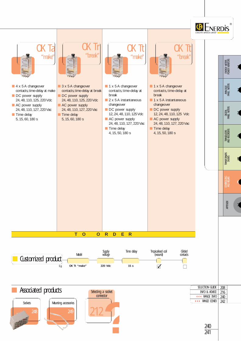
s OK TA/TR/TT RANGEPlug-in relays with 2, 3 or 4 changeover contacts (5A), make orbreak time delay adjustable by potentiometer.
The OK Ta/Tr/Tt relays enables the user to adjust the time-delay for a given fixedrating.
The OK Tt offers mixed contacts: OK Tt at make (1 time-delay changeover contactand 2 instantaneous changeover contacts) and OK Tt at break (1 time-delay changeo-ver contact and 1 instantaneous changeover contact).
Description
PRODUCT ADVANTAGES
HIGHLY RELIABLE for intensive used in severe conditions
TIME DELAY at contact make or break
MAGNETIC BLOW-OUT as standard
MIXED CONTACT MODELS: time delay and instantaneous
OK Ta “make”
OK Tr “break”
OK Tt “break”
OK Tt “make” Time delay adjusta-ble by rotating-switch potentiome-ter for a givenrating
Transparent coverfor permanentcontact statusdisplay
Output Fastonlugs connectors5 x 0.8 mm
Dimensions (in mm)OK Ta, OK Tr range OK Tt range
Associated products
4 x 5 A changeovercontacts, time-delay at make
DC power supply 24, 48, 110, 125, 220 Vdc
AC power supply 24, 48, 110, 127, 220 Vac
Time delay5, 15, 60, 180 s
3 x 5 A changeovercontacts, time-delay at break
DC power supply 24, 48, 110, 125, 220 Vdc
AC power supply 24, 48, 110, 127, 220 Vac
Time delay 5, 15, 60, 180 s
1 x 5 A changeovercontacts, time-delay atbreak
2 x 5 A instantaneouschangeover
DC power supply 12, 24, 48, 110, 125 Vdc
AC power supply 24, 48, 110, 127, 220 Vac
Time delay 4, 15, 50, 180 s
OK Ta“make”
OK Tr“break”
OK Tt“make”
T O O R D E R
1 x 5 A changeovercontacts, time-delay atbreak
1 x 5 A instantaneouschangeover
DC power supply 12, 24, 48, 110, 125 Vdc
AC power supply 24, 48, 110, 127, 220 Vac
Time delay 4, 15, 50, 180 s
OK Tt“break”
Supply Time delay Tropicalised coil GildedModel voltage (wound) contacts
OK Tt “make” 220 Vdc 15 s
240241
248
Sockets
249
Mounting accessories
SELECTION GUIDEINFO & ADVICE
RANGE INFO RANGE CONTD
208216240242
Customized product
Selecting a socketconnector
?212
E.g.
3
4
5
6
ENER
GY M
ETER
S PO
WER
MON
ITORS
ANAL
OGUE
PA
NEL
METE
RSDIGITA
L PA
NEL
METE
RSTR
ANSD
UCER
SAN
D RE
CORD
ERS
TRAN
SFOR
MERS
SHUN
TSCO
NTRO
LLING
AND
RELA
YS
7
APPE
NDIX
2
1

Time
delay
rela
ysCo
ntrollin
g an
d relay
s
Electrical specifications
OK Ta/Tr/Tt range
Models OK Ta OK Tr OK Tt make OK Tt breakDC coil supplyNominal voltage (Un) 24 48 110 125 220 Vdc 12 24 48 110 125 Vdc
Operating range 0.85…1.1 Un (+20 °C) 0.85…1.1 Un (+20 °C)
Consumption 4 W 4.5 W
Break voltage 0.2 Un 0.2 Un
AC coil supplyNominal voltage (Un) 24 48 110 127 220 Vac 24 48 110 125 127 220 Vac
Operating range 0.85 to 1.1 Un (+20 °C) 0.85 to 1.1 Un (+20 °C)
Consumption 4 VA 5 VA
Break voltage > 0.1 Un > 0.1 Un
ContactsModels OK Ta OK Tr OK Tt make OK Tt break
at make 4 RT 1 RTTime-delay contacts
at break 3 RT 1 RT
Instantaneous contacts 2 RT 1 RT
Nominal thermal current 5 A 5 A
Type Ag Ag
Maximum operating voltage 250 Vdc or 300 Vac 250 Vdc or 300 Vac
Maximum intermittent current 100 A during 10 ms 100 A during 10 ms
Pressure of make contact 0.5 N 0.5 N
Pressure of break contact > 0.2 N > 0.2 N
Time delayRating (in secs) 5 15 60 180 1 4 14 50 180
Adjustment range 1s: 20 to 100 % Other ratings: 10 to 100 % 1s: 15 to 100 % Other ratings: 5 to 100 %
Accuracy 2 % of Tn ± 2.5 % of Tn
Temperature coefficient 0.07 % / °C 0.07 % / °C
DC 0.5 % of T -Repeatability
AC 0.5 % of T + 20 ms -
Minimum reset timeDC 0.5 s 0.1 s
AC 0.5 s 1.5 s
Sensitivity to power interruptions
Reset to zero Reset in case of Reset in case of timeof time delay interruption > 20ms Reset of time delay > time delay
Dielectric strengthCoil/contacts: 2,000 V - 50 Hz - 1 minuteContact/contact: 1,000 V - 50 Hz - 1 minuteInsulation resistance: under 500 Vdc as per IEC 61810: > 1,000 MΩMechanical life cycle: 20 x 106 operationsEnvironmentOperating temperature: -10 °C to +50 °C Relative humidity: ″ 80 %Storage temperature: -25 °C à +70 °CResistance to vibrations: 5 g - 10 to 55 Hz - 1 minute as per EN 61810Resistance to shocks (energized relay): 20 g - 11 ms - 1/2 sine as per EN 61810Weight: 270 gProtection rating: IP 40Compliance with standards: EN 61810, Materials compliance NF-F 16-101,NF-F 16-102 and IEC 695-2-1
General characteristics
Plug-in relays with 2, 3 or 4 changeover contacts (5A),

AC breaking capacity
A - 48 V, 50 Hz, cos ϕ = 1B - 110 V, 50 Hz, cos ϕ = 1C - 110 V, 50 Hz, cos ϕ = 0.7D - 220 V, 50 Hz, cos ϕ = 1E - 220 V, 50 Hz, cos ϕ = 0.7F - 440 V, 50 Hz, cos ϕ = 1
DC breaking capacity
A - 24 V, L/R = 0B - 48 V, L/R = 0C - 24 V, L/R = 40 msD - 48 V, L/R = 40 msE - 72 V, L/R = 20 msF - 110 V, L/R = 10 ms
OK Tt “make” OK Tt “break”
OK Ta OK Tr
OK Tt “make” OK Tt “break”
Electrical connections
Operation
242243
208216240
SELECTION GUIDEINFO & ADVICE
RANGE INFO
3
4
5
6
ENER
GY M
ETER
S PO
WER
MON
ITORS
ANAL
OGUE
PA
NEL
METE
RSDIGITA
L PA
NEL
METE
RSTR
ANSD
UCER
SAN
D RE
CORD
ERS
TRAN
SFOR
MERS
SHUN
TSCO
NTRO
LLING
AND
RELA
YS
7
APPE
NDIX
2
1

Time
delay
rela
ysCo
ntrollin
g an
d relay
s
F-OK TBAOMake time-delay relay
PRODUCT ADVANTAGES
HIGHLY RELIABLE for intensive use in severe conditions
SNCF/RATP-APPROVED (French rail/Paris area suburban rail & metro)
DELAY TIMER ADJUSTABLE via external link
F-OK TBOR Break time-delay relayFitting bracketsystem
Dimensions asper F-OK B
F-OK TBAO / TBOR RANGEPlug-in solid state-time-delay relays, delay timer adjustable viaexternal link
The F-OK TBAO model is a solid-state "make" time-delay relay, activated on power up.
The delay timer delays triggering loads for the chosen interval.
The F-OK TBOR model is a solid-state "break" time-delay relay, comprising a perma-nent power supply and command teminal.The relay goes into operation upon recep-tion of the command signal.When this has finished, the relay is maintained in operationfor the time set.
Description
1010
5345
85,5
105
8
45
Dimensions (in mm)

Electrical specifications
Dielectric strength2,000 V – 50 Hz – 1 minuteInsulation resistance under 500 Vdc as per IEC 61810: > 1,000 MΩMechanical life cycle: -25 °C to +70 °CResistance to vibrations: 2 g – 10 to 120 HzResistance to shocks: 30 g during 18 msProtection rating: IP 40Compliance with standards: EN 61 840, Materials compliance NF-F 16101, NF-F 16 102 and IEC 695-2-1SNCF (French rail) 4MCE 12281 – RATP (Paris suburban rail & metro)EZ 5006, CF 62003
General characteristics
Electrical connections
Model Supply ReferenceF-OK TBAO 72 Vdc P01 4659 02F-OK TBOR 72 Vdc P01 4659 01
T O O R D E R
Model Supply
F-OK TBAO 24 Vdc
244245
248
Sockets
249
Mounting accessories
Associated products 208216240
SELECTION GUIDEINFO & ADVICE
RANGE INFO
Customized products
Selecting a socketconnector
?212
E.g.
Models F-OK TBAO F-OK TBORMake time delay Break time delayapplied to relay applied to relay1 solid state output pilots the coil of the commanded relay
Time-delayTime-delay range 0.5 1 2 3 4 5 10 20 30 40 sRepeat accuracy 2 % in nominal conditionsAccuracy ± 10 % in nominal conditionsCommandNominal voltage 24 72 VdcMaximum voltage 33 90 VdcMinimum voltage 16.8 50 VdcReset time ″ 50 msOutputNumber 1Maximum outage 0.8 A 0.25 APermitted maximum overvoltage 1,500 V peak
3
4
5
6
ENER
GY M
ETER
S PO
WER
MON
ITORS
ANAL
OGUE
PA
NEL
METE
RSDIGITA
L PA
NEL
METE
RSTR
ANSD
UCER
SAN
D RE
CORD
ERS
TRAN
SFOR
MERS
SHUN
TSCO
NTRO
LLING
AND
RELA
YS
7
APPE
NDIX
2
1

Functio
n relay
sCo
ntrollin
g an
d relay
s FUNCTION RELAYS RANGEPlug-in industrial relays for a wide range of specific functions
OK CL flashing relay
PRODUCT ADVANTAGES
WIDE RANGE OF FUNCTIONS: bistable, communication functions, etc.
HIGHLY RELIABLE for intensive use in severe conditions
CUSTOMIZED FUNCTIONS ON REQUEST
The OK CL is a flashing relay from the OK range.The coil is supplied by one of thebreak contacts of the relay.A capacitor on the coil's terminals prevents hum and acti-vates the break time delay of the relay.
Description
114
10
61,5
42
35
10
74
121
4545
Dimensions (in mm)
Output Fastonlug connectors(5x0.8) mm
Transparent coverfor permanentcontact statusdisplay

Electrical specifications
Model OK CLDC coil supplyNominal voltage (Un) 24 48 110 220 Vdc
Operating range 0.8 to 1.2 Un (at +20 °C)
Consumption 3 W
AC coil supplyNominal voltage (Un) 24 48 110 220 Vac
Operating range 0.8 to 1.2 Un (at +20 °C)
Consumption 3 VA
Contacts Number 1 RT
Nominal thermal intensity 10 A
Type Ag
Maximum operating voltage 350 Vdc or 440 Vac
Maximum intermittent current 150 A during 10 ms
Pressure of contact > 0.3 N at break
> 0.8 N at make
Time delayAdjustable from 60 to 100 operations/minute
Dielectric strengthCoil/contacts: 2,000 V - 50 Hz - 1 minuteContact/contact: 2,000 V - 50 Hz - 1 minuteInsulation resistance under 500 Vdc as per IEC 61810: > 1,000 MΩMechanical life cycle: depending on modelEnvironment:Operating temperature: depending on modelStorage temperature: -40 °C to +85 °CRelative humidity: < 80 %Resistance to vibrations: 5 g - 5 to 60 Hz - 1 minute as per EN 61810Resistance to shocks (energized relay): 30 g - 11 ms - 1/2 sine as per EN 61810Weight: 0.3 kgProtection rating: IP 20 (IP 40 on request)Compliance with standards: EN 61810, Materials compliance NF-F 16-101,NF-F 16-102 and CEI 695-2-1
General characteristics
Model Power supply ReferenceOK CL 220 Vac P01 4540 07
T O O R D E R
Model Supply voltage Time delay Tropicalization
OK CL 220 Vdc 60 operations/min
Other function relays available on request
246247
248
Sockets
249
Mounting accessories
Associated products 208216246
GENERAL OVERVIEWINFO & ADVICE
RANGE INFO
Customized productsE.g.
3
4
5
6
ENER
GY M
ETER
S PO
WER
MON
ITORS
ANAL
OGUE
PA
NEL
METE
RSDIGITA
L PA
NEL
METE
RSTR
ANSD
UCER
SAN
D RE
CORD
ERS
TRAN
SFOR
MERS
SHUN
TSCO
NTRO
LLING
AND
RELA
YS
7
APPE
NDIX
2
1

Rear blade connector
SOCKETS FOR THE POK/OK/F-OK RANGE
Contact ensured by beryllium-bronze loop.
Self-extinguishing moulded part does not affect contact pressure.
Easy fitting: relay clips on to socket.
Direct link without internal soldering.
Descriptions
250
250
Rear screw connector
251
Rear solder connector
251
Rear connector for printed circuit
252
Front blade connector
252
Front screw connector
Front and rear socket connectors for thePOK, OK and F-OK ranges
POK and OK Ninstantaneousrelays
Socket No. 47
Locking springensures relayremains locked intosocket whateverthe position
PRODUCT ADVANTAGES SELF-CLEANING CONTACTS
EXTRA-STRONG contacts
COMPLIANCE with NF-F 16-101 and 16-102
IP 20 PROTECTION RATING to prevent finger contact
+
+
=POK and OK Nrelays on socketno. 47N lockedrespectively bysprings RPB43and RC43
Sockets
Controllin
g an
d relay
s

Locking spring model ReferenceRPB 43 (set of 10) P01 4001 59RC 43 (set of 6) P01 4001 61RL 43 (set of 6) P01 4001 64RPB 48 (set of 10) P01 4001 58RC 48 (set of 6) P01 4001 79RL 48 (set of 6) P01 4001 87
Model ReferenceRed safety blanks (set of 50) P01 4002 31Black safety blanks (set of 50) P01 4002 14Red male/female safety blanks (set of 50) P01 4002 30Black male/female safety blanks (set of 50) P01 4002 13Transverse double lug no. 25 P01 4001 37Longitudinal double lug no. 26 P01 4001 38
RC48:90
RPB48:43
6
49
RL48:100
RL:115 RC:100
6
49
RPB43:53
locking springscontacts RPB43 RC43/RL43 No. 85
53F 8
screw 43F 16
73F 24
54F 8
43DF 16
74F 24
blade 47N 2 x 16
55 16
84F 16 63A 16
solder 56 16
printedcircuit 65F 16
locking springscontacts RPB43 RPB48 RC43 RC48
RL 43 RL 4850BF 8
screw 48BF 16
78BF 16
51F 16
48F 16
blade 78F 16
68A 16
68C 16
REAR SOCKETCONNECTORS
FRONT SOCKETCONNECTORS
T O O R D E R
Locking springLocking spring ensures relay remains lockedinto socket whatever the position.
Double lug connectorDouble lug connectors enable the user to join or toconnect 2 contacts length-wise or cross-wise dependingon the model.
Safety blanksThe male/female safety blank no. 59 is a hexagonal safetyblank for insertion in the safety blank recesses on the relayand relay socket connector.
248249
Rear socketconnectors Front socket
connectors
Mounting accessories
SELECTION GUIDEINFO & ADVICE
RANGE INFO RANGE CONTD
208216248250
Selecting a socketconnector
?212
3
4
5
6
ENER
GY M
ETER
S PO
WER
MON
ITORS
ANAL
OGUE
PA
NEL
METE
RSDIGITA
L PA
NEL
METE
RSTR
ANSD
UCER
SAN
D RE
CORD
ERS
TRAN
SFOR
MERS
SHUN
TSCO
NTRO
LLING
AND
RELA
YS
7
APPE
NDIX
2
1

Sockets
Controllin
g an
d relay
s
Socket Contacts Reference53F 8 P01 4002 18
Socket Contacts Reference43DF 16 P01 4002 19
Socket Contacts Reference74F 24 P01 4002 20
Rear double-blade connector (5 x 0.8 mm)
Operating temperature: -25 °C to +55 °C Weight: 35 g
Rear double-blade connector(5 x 0.8 mm) Operating temperature: -25 °C to +55 °C Weight: 80 g
54F8 contacts
Rear double-blade connector(5 x 0.8 mm)
Operating temperature: -25 °C to +55 °C Weight: 120 g
NF Compliant
43DF16 contactsNF Compliant
74F24 contactsNF Compliant
SOCKETS FOR THE POK/OK/F-OK RANGEREAR BLADE CONNECTORS
3
2
62
3
2
4
1
T O O R D E R
Socket Contacts Reference53F 16 P01 4002 15
Socket Contacts Reference43F 16 P01 4002 16
Socket Contacts Reference73F 24 P01 4002 17
Rear screw connector (8 screws M3 x 6) Operating temperature: -25 °C to +55 °C Weight: 35 g
Rear screw connector (16 screws M3 x 6) Operating temperature: -25 °C to +55 °C Weight: 80 g
53F8 contacts
Rear screw connector (24 screws M3 x 6) Operating temperature: -25 °C to +55 °C Weight: 120 g
43F16 contacts
73F24 contacts
REAR SCREW CONNECTORS
T O O R D E R
NF CompliantNF Compliant
NF Compliant
Circuit diagram legend1. Connection (blade, screw, lug or solder)2. Recesses for safety blanks3. Fastening hooks or holes for screw connectors4. Locking spring
NF Compliant : 5. Compliance with standardsNF-F 16-101/102
Profileas per 53F
Profileas per 53F
Profileas per 54F
Profileas per 54F

Socket Contacts Reference56A 16 P01 4001 49
Socket Contacts Reference65F 16 P01 4001 53A
Socket Contacts Reference84F 24 consult usRelay adapter kit P01 4002 01Male/female safety blank P01 4002 02Full safety blank P01 4002 03
For solder connector printed circuits Operating temperature: -25 °C to +55 °C Weight: 50 g
5616 contacts
65F16 contactsNF Compliant
84F16 contactsNF Compliant
Rear blade connector with strap Operating temperature: -25 °C to +70 °C Weight: 120 g
Rear solder connector Operating temperature: -25 °C to +55 °C Weight: 50 g
218
POK relay
226
OK relay
230
F-OK relay Associated products
REAR CONNECTORS
REAR BLADE CONNECTORS
Socket Contacts Reference47N 2x16 P01 4001 41
Socket Contacts Reference55 16 P01 4001 48
Socket Contacts Reference63A 16 P01 4001 52
Rear single-blade connector (5 x 0.8 mm)
Operating temperature: -25 °C to +55 °C Weight: 80 g
47N2x16 contacts
5516 contacts
63A16 contacts
T O O R D E R
REAR SOLDER CONNECTORS REAR BLADE CONNECTORSFOR PRINTED CIRCUITS
Rear single-blade connector (5 x 0.8 mm)
Operating temperature: -25 °C to +55 °C Weight: 50 g
Rear single-blade connector (5 x 0.8 mm)
Material: heat-resistant ABS Operating temperature: -25 °C to +55 °C Weight: 75 g
249
Mounting accessories
250251
T O O R D E R
SELECTION GUIDEINFO & ADVICE
RANGE INFO RANGE CONTD
208216248252
3
4
5
6
ENER
GY M
ETER
S PO
WER
MON
ITORS
ANAL
OGUE
PA
NEL
METE
RSDIGITA
L PA
NEL
METE
RSTR
ANSD
UCER
SAN
D RE
CORD
ERS
TRAN
SFOR
MERS
SHUN
TSCO
NTRO
LLING
AND
RELA
YS
7
APPE
NDIX
2
1
commendedmountingdirection

Sockets
Controllin
g an
d relay
s
Circuit diagram legend1. Blade or screw connectors2. Recesses for safety blanks3. Holes and recesses for screw connectors C M4 x 254. Locking spring
Socket Contacts Reference51F 8 P01 4002 08
Socket Contacts Reference48F 16 P01 4002 06
Socket Contacts Reference78F 24 P01 4002 09
Front double-blade connector Operating temperature: -25 °C to +55 °C Weight: 35 g
51F8 contacts
Front double-blade connector Operating temperature: -25 °C to +55 °C Weight: 105 g
NF Compliant
48F16 contactsNF Compliant
78F16 contactsNF Compliant
SOCKETS FOR THE POK/OK/F-OK RANGEFRONT BLADE CONNECTORS
T O O R D E R
Socket Contacts Reference50BF 8 P01 4002 1050BF IP20 8 P01 4002 10A50 IP20 IDIN 8 P01 4002 33
Socket Contacts Reference48BF 16 P01 4002 0448BF IP20 16 P01 4002 04A48B IP20 IDIN 16 P01 4002 34
Socket Contacts Reference78BF 24 P01 4002 0778BF IP20 24 P01 4002 07A78BF IP20 IDIN 24 P01 4002 35
Front double-blade connector Operating temperature: -25 °C to +55 °C Weight: 35 g
Front double-blade connector Operating temperature: -25 °C to +55 °C Weight: 85 g
50BF8 contacts
Front double-blade connector Operating temperature: -25 °C to +55 °C Weight: 120 g (IP20) - 105 g
48BF16 contacts
78BF16 contacts
FRONT SCREW CONNECTORS
T O O R D E R
NF CompliantNF Compliant
NF Compliant
Front double-blade connector Operating temperature: -25 °C to +55 °C Weight: 75 g
NF Compliant : 5. Compliance with standardsNF-F 16-101/102
Profileas per 51F
Profileas per 51F
Profile asper 50BF
Profile as per 50BF

218
POK relay
226
OK relay
230
F-OK relay
249
Mounting accessories
Associated products
FRONT CONNECTORS
FRONT BLADE CONNECTORS
Socket Contacts Reference68A 16 P01 4001 54
Socket Contacts Reference68C 16 P01 4001 98
Model ReferenceFlange Consult us
Model ReferencePlate P01 4001 99
Model ReferenceHandle Consult us
Front double-blade connector Operating temperature: -25 °C to +55 °C Weight: 120 g
68A16 contacts
68C16 contacts
T O O R D E R
Front double-blade connector Operating temperature: -25 °C to +55 °C Weight: 80 g
Clip-on plate for DIN rail 46277 For fitting to asymmetric DIN rail (width: 32 mm) For fitting to symmetric DIN rail hat section (width: 35 mm)
Fitting flange no. 85 For direct locking of OK relays to socket
connectors nos. 55, 56 or 63 A
Retractable central handle for Ok familyof relays
FRONT FLANGE CONNECTOR FRONT PLATE CONNECTOR
HANDLE
252253
1. Direct fitting of POK or BiPOK relay
2. Direct fitting of socket connector toplateFits to connectors nos. 48F, 48BF,68A, 68C, 78F, 78BF
3. Direct fitting of POK or OK relay
T O O R D E R
208216248
SELECTION GUIDEINFO & ADVICE
RANGE INFO
Selecting a socketconnector
?212
3
4
5
6
ENER
GY M
ETER
S PO
WER
MON
ITORS
ANAL
OGUE
PA
NEL
METE
RSDIGITA
L PA
NEL
METE
RSTR
ANSD
UCER
SAN
D RE
CORD
ERS
TRAN
SFOR
MERS
SHUN
TSCO
NTRO
LLING
AND
RELA
YS
7
APPE
NDIX
2
1

Sockets
Controllin
g an
d relay
s SOCKETS FOR THE RI RANGE
Front connector
Front and rear socket connectors for the RI range
PRODUCT ADVANTAGES COMPACT DESIGN
NO OVERHEATING: nickelled metal connections
MOUNTING ON PRINTED CIRCUIT
Mounting accessoriesModel Relay Reference RC/RI lockingspring (set of 6) Standard RI P01 4002 27
RL/RI-1 lockingspring (set of 6) High stroke RI P01 4002 28
Rear connectorRI 270 relay
Socket connectorno.111
Locking spring RC/RI
RI 270 onsocket connectorno.111
+
+
=

FRONT CONNECTOR REAR CONNECTOR
Socket Contacts Reference110 11 P01 4002 21
Socket Contacts Reference111 11 P01 4002 23
Socket Contacts Reference112 11 P01 4002 25
Rear solder connector Operating temperature: -25 °C to +70 °C Weight: 30 g Connection: 11 lugs 2.8 x 0.5 mm Fitting screws: 2 x 3.2 mm max.
No. 11011 contactsNF Compliant
No. 11111 contactsNF Compliant
No. 11211 contactsNF Compliant
T O O R D E R
Rear connector for printed circuit Operating temperature: -25 °C to +70 °C Weight: 30 g Connection/fitting:
11 solder connections
Rear screw connector Operating temperature: -25 °C to +70 °C Weight: 50 g Connection: 11 screw terminals M3 x 5 Fitting screws: 2 x 3.2 mm max.
Socket Contacts ReferenceEmbase 170 17 P01 4002 22
Socket Contacts Reference171 17 P01 4002 24
Socket Contacts Reference172 17 P01 4002 26
Rear solder connector Operating temperature: -25 °C to +70 °C Weight: 40 g Connection: 17 connection lugs 2.8 x 0.5 mm Fitting screws: 2 x 3.2 mm max.
No. 17017 contactsNF Compliant
No. 17117 contactsNF Compliant
Front connector for printed circuit Operating temperature: -25 °C to +70 °C Weight: 40 g Connection/fitting:
17 solder connections
No. 17217 contactsNF Compliant
T O O R D E R
Front screw connector Operating temperature: -25 °C to +70 °C Weight: 60 g Connection: 17 screw terminals M3 x 5 Fitting screws: 2 x 3.2 mm max.
RI relay Mounting accessories
Associated products
254255
208216254
SELECTION GUIDEINFO & ADVICE
RANGE INFO
Selecting a socketconnector
?212222 254
3
4
5
6
ENER
GY M
ETER
S PO
WER
MON
ITORS
ANAL
OGUE
PA
NEL
METE
RSDIGITA
L PA
NEL
METE
RSTR
ANSD
UCER
SAN
D RE
CORD
ERS
TRAN
SFOR
MERS
SHUN
TSCO
NTRO
LLING
AND
RELA
YS
7
APPE
NDIX
2
1

Sockets
Controllin
g an
d relay
s SOCKET CONNECTORS FOR RE RANGE
Tin-plated bronze loop contacts.Direct link-up without soldering.
Description
Mounting accessories
Rear screw connector
Front screw connector
Front blade connector
Front and rear socket connectors for RE range
PRODUCT ADVANTAGES
GREATER CONTACT STRENGTH
SELF-CLEANING CONTACTS
Model ReferenceLocking pin ACCA 4162DFR310 panel mounting terminal strip ACCA 4158Fitting strap for mounting on bar ACCA 4159
Rear blade connectorRE3000 relay
ERL 310socket connector
RE3000 relayon ERL 310socket connector
+
=
Model Sockets ReferenceSymmetric DINrail mounting EVL 3100 - EVV 3100 EVVA 1000
Asymmetric DIN rail mounting EVL 3100 - EVV 3100 EVVA 1001

REAR CONNECTOR
FRONT SOCKET CONNECTORS
Socket Contacts ReferenceERV 310 14 ERVA 4153
Socket Contacts ReferenceERL 310 14 ERLB 4154
Socket Contacts ReferenceERL 320 14 ERLC 4155
Rear blade connector Materials: self-extinguishing glass-filled
thermoplastic Operating temperature: -10 °C to +55 °C Weight: 100 g
ERV 31014 contactsNF Compliant
ERL 31014 contactsNF Compliant
ERL 32014 contactsNF Compliant
T O O R D E R
Rear blade-blade connector Materials: self-extinguishing glass-filled
thermoplastic Operating temperature: -10 °C to +55 °C Weight: 100 g
Rear screw connector Materials: self-extinguishing glass-filled
thermoplastic Operating temperature: -10 °C to +55 °C Weight: 100 g
Socket Contacts ReferenceEVV 3100 14 EVVA 4150
Socket Contacts ReferenceEVL 3100 14 EVVB 4149
Front blade connector Operating temperature: -10 °C to +55 °C Weight: 100 g
EVV 310014 contactsNF Compliant
EVL 310014 contactsNF Compliant
T O O R D E R
Front screw connector Operating temperature: -10 °C to +55 °C Weight: 100 g
RE relay Mounting accessories
Associated products
256257
208216256
SELECTION GUIDEINFO & ADVICE
RANGE INFO
Selecting a socketconnector
?212
232 256
3
4
5
6
ENER
GY M
ETER
S PO
WER
MON
ITORS
ANAL
OGUE
PA
NEL
METE
RSDIGITA
L PA
NEL
METE
RSTR
ANSD
UCER
SAN
D RE
CORD
ERS
TRAN
SFOR
MERS
SHUN
TSCO
NTRO
LLING
AND
RELA
YS
7
APPE
NDIX
2
1

Notes
& com
ments