Embed Size (px)
Citation preview

DIGITAL MICROWAVE SYSTEM AND PRODUCE SERIES

DIGITAL MICROWAVE SYSTEM AND PRODUCE SERIES
Company Profile
Overview
Equipment Introduce
System Features
1st: Card Structure
2nd: 4E1-16E1 expand smoothly
3rd: Support E1 and IP at the same time
4th: Super embedded LCD NMS
5th: 1+1 different frequency standby
6th: 1+1 same frequency hot-standby
7th: 1+1 SD and without SD
8th: Base on SNMP network management system
9th: SNMP network management
10th: Professional network planning software
Products Application
Typical mode of operation solution
1st: Mobile base station interconnection
2nd: WiMAX base station interconnection
3rd: Enterprise voice and data Access
4th: Dedicated transparent transmission channels
5th: Emergency communication
Super network
1
2
3
7
7
7
7
7
7
8
8
8
8
8
10
10
10
10
11
11
11
12
CO
NTEN
TS

B RIEF INTRODUCTION OF THE COMPANY
1
DIGITAL MICROWAVE SYSTEM AND PRODUCE SERIES
Centron Communications Technologies Fujian Co., Ltd (hereinafter called CCTF) is one of the earliest enterprises that engaged in information and communications filed. It established in 1989, and now is the subsidiary of Centron Telecom International Holding Limited, a company listed on main board of HKSE. (Stock Code: 1155)
CCTF is dedicated to providing the clients with professional and cost effective information solutions. It has R&D centers respectively in Quanzhou, Shenzhen, Beijing and Xi’an. Now it has three product lines covering wireless coverage, wireless transmission and wireless access. It possesses several core technology and many independent intellectual property rights.
The production center of CCTF is located in Quanzhou, which is famous for its reputation of garden city and the starting point of Sea Silk Road. The total floor area is over 68,000 square meters, 60% of which is for standard communications equipment workshop. The annual production capacity can reach RMB 1,000,000,000. After years of development, a new company structure has been formed by four centers being established in four cities: the domestic marketing center in Beijing, overseas marketing center in Shenzhen, R&D center in Xi’an, and the production center in Quanzhou. This basic structure helps CCTF to build an integrated platform of R&D, manufacture and marketing, by which CCTF can adapt it to the large-scale development in the future.
Now, CCTF has established strategic partnership with many global telecommunication magnates, and tens of thousands pieces/sets of equipments are operating in the system of China Mobile, China Unicom, China Telecom, etc. Up to now, CCTF has set up 31 sales and service branches. Meanwhile overseas service branches have being established in Pacific Asia and Africa to offer updated optimization solutions and more efficient services.
CCTF focuses closely on the development of mobile communications industry. With innovative service concept and advanced technology, CCTF devotes itself to providing integrated solution and convenient communications platform.
SUMMARY
2
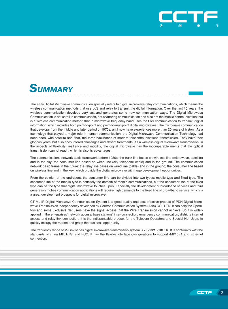
The early Digital Microwave communication specially refers to digital microwave relay communications, which means the wireless communication methods that use LoS and relay to transmit the digital information. Over the last 10 years, the wireless communication develops very fast and generates some new communication ways. The Digital Microwave Communication is not satellite communication, not scattering communication and also not the mobile communication; but is a wireless communication method that in microwave frequency band uses the LoS communication to transmit digital information, which includes both point-to-point and point-to-multipoint digital microwaves. The microwave communication that develops from the middle and later period of 1970s, until now have experiences more than 20 years of history. As a technology that played a major role in human communication, the Digital Microwave Communication Technology had been seen, with satellite and fiber, the three backbones of modern telecommunications transmission. They have their glorious years, but also encountered challenges and absent treatments. As a wireless digital microwave transmission, in the aspects of flexibility, resilience and mobility, the digital microwave has the incomparable merits that the optical transmission cannot reach, which is also its advantages.
The communications network basic framework before 1980s: the trunk line bases on wireless line (microwave, satellite) and in the sky; the consumer line based on wired line (city telephone cable) and in the ground. The communication network basic frame in the future: the relay line bases on wired line (cable) and in the ground; the consumer line based on wireless line and in the key, which provide the digital microwave with huge development opportunities.
From the opinion of the end-users, the consumer line can be divided into two types: mobile type and fixed type. The consumer line of the mobile type is definitely the domain of mobile communications, but the consumer line of the fixed type can be the type that digital microwave touches upon. Especially the development of broadband services and third generation mobile communication applications will require high demands to the fixed line of broadband service, which is a great development prospects for digital microwave.
CT-ML IP Digital Microwave Communication System is a good-quality and cost-effective product of PDH Digital Micro-wave Transmission independently developed by Centron Communication System (Asia) CO., LTD. It can help the Opera-tors and some Exclusive Net users have the signal access that the Wire Transmission cannot achieve. So it is widely applied in the enterprises’ network access, base stations’ inter-connection, emergency communication, districts internet access and relay link connection. It is the indispensable product for the Telecom Operators and Special Net Users to quickly occupy the market and grasp the business opportunity.
The frequency range of M-Link series digital microwave transmission system is 7/8/13/15/18GHz. It is conformity with the standards of china MII, ETSI and FCC. It has the flexible interface configurations to support 4/8/16E1 and Ethernet connection.

PRODUCTS INTRODUCTION
3
DIGITAL MICROWAVE SYSTEM AND PRODUCE SERIES
Transmission Network Access Network
Cover NetworkOperation
Core Network
Core switch:PSTN Exchanger
GSM BSC
CDMA BSC
3G TD RNC
Core Router
Transmission solution:Microwave PDH
Microwave SDH
Optical PDH
Optical SDH
Optical IP Modulation
and Demodulation
and etc Transmission
of IP, E1 and STM-1
Cover solution:Base Station Repeater
Indoor distribution
Optical EPON
Wireless AP
Wireless access
Wireless net bridge
Service realization:mobile telephone,
fax and PC,
Video Terminal,
Multiplexer
The CT-ML’s Location in the Network
The products of CT-ML Digital Microwave Transmission System include ODU, IDU, Middle Frequency Cable and Antenna, which compose a Terminal Station that can timely manage the microwave network through Network Manage-ment System. The working frequency is 7G, 8G, 13G, 15G, 18G, and the max. Transmission Capacity is 32Mbps. It has 4E1, 8E1, 16E1 four Baseband connectors that can select and assemble at will. There also have repeaters to cooperate with the solution.
Cover 7G/8G/13G/15G/18G Frequency Band
E1 port support, capacity 4 E1-16E1
LAN (IP) port support, the largest bi-direction transmission rate 32/32=64 Mbps
4
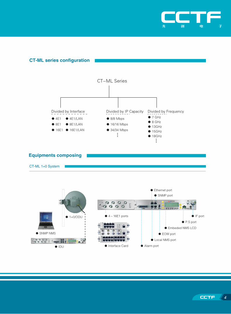
CT-ML series configuration
Equipments composing
CT-ML 1+0 System
● P.S port
● IF port
● Embeded NMS LCD
● SNMP port
● EOW port
● Alarm port
● Ethernet port
● Local NMS port
● Interface Card
● 4-16E1 ports
● SNMP NMS
● 1+0/ODU
● IDU
CT-ML Series
● 8/8 Mbps
● 16/16 Mbps
● 34/34 Mbps
Divided by IP Capacity
● 7 GHz● 8 GHz● 13GHz● 15GHz● 18GHz
Divided by Frequency
● 4E1 ● 4E1/LAN
● 8E1 ● 8E1/LAN
● 16E1 ● 16E1/LAN
Divided by Interface…
…

5
DIGITAL MICROWAVE SYSTEM AND PRODUCE SERIES
● RS Interface● 4-16 E1 Ports ● RSU Connecting Interface
● Switching Control Key-press
● RS connecting Cable
Manual switching ●
● Co-frequency backup
● Different frequency backup
CT-ML 1+1 System
ODU Description
● GND
● IF cable connecter
● IF cable● Antenna combiner● Receiving level Monitoring ● Antenna connecter ● Antenna● ODU
● IDU
● IDU
● RSU
● 1+1/ODU+combiner
● 1+1/ODU

6
Relay Transmitting
★ Passive Transmitting Using the high-gain, wide-radii passive antenna to transmit
★ Active transmitting
CT-ML Digital Microwave Transmission system’s application range
Telecom Operators
Telecom Operators such as China Telecom, China Netcom, China Unicom,
China Mobile, CTT, Satellite Communication and Radio and TV Administration
ISP Operators
Dedicated Network for Public Utility
Dedicated Network for Electricity, Waterpower, Coal, Mining,
Forestry, Large building sites and so on
The Governmental Network
Dedicated Network for Banking, Taxation,
Traffic, Public Security, Transport
Emergency Communications
Army Private Network
Customer Premises Network
Emergency Communications
● Solar panel
● Antenna + ODU
● Passive antenna

7
DIGITAL MICROWAVE SYSTEM AND PRODUCE SERIES
SYSTEM FEATURE 1st: Card structure
Module design, only change the interface card, which can change the radio system to the capacity 4E1/8E1/16E1.
Provide the 75ohm BNC interface and 120ohm RJ48 interface.
2nd: 4E1-16E1 expand smoothly
When the system capacity expands, only to do is change the interface card, you can get 4E1-8E1-16E1.
� When the system capacity is expand , ODU don’t need to change, it can adjust the bandwidth to 7M/14M/28M
according to the IDU’s capacity.
3rd: Support E1 and IP at the same time
The perfect combine of the E1 and IP, M-Link can support E1 interface and IP interface at the same time, the
capacity can divided dynamically.
� E1 without use can be packed automatically to transport through IP.
5th: 1+1 different frequency standby
Support the real 1+1 mode of different frequency standby.
Support the standby of different frequency or sub-frequency.
The switch can be set to automatic and manual.
The fault radio unit can be changed during the ordinary working of the standby.
4th: Super embedded LCD NMS
Embedded NMS and LCD function, support all the configuration and display (set the frequency point, power,
etc),very convenience for the engineering of operating and maintaining the radio onsite, don't need the help of
other equipments.
The alarm of the temperature of ODU and the alarm of receive level, preventing the fault in advance.
Kinds of alarm display.
Kinds of testing recycling.
Important alarm light. Set password, assure the security.
Can watch two terminals at one site.
BER testing inside, watching the quality of communication of the path at any moment.各种告警指示灯

8
6th: 1+1 same frequency hot-standby
Support the real 1+1 mode of same frequency hot standby.
The switch can be set to automatic and manual.
The fault radio unit can be changed during the ordinary working of the standby.
7th: 1+1 SD and without SD
When the system use hot standby of same frequency, it can be configured as SD structure with two antennas.
No matter what kind of structure the system use, same frequency or different frequency hot standby, they all
can be use the combiner and one antenna, that is without SD.
8th: Base on SNMP network management system
Support SNMP V2.0 protocol, can manage the radio system through the third network management software,
can manage about 4096 links of radio.
9th: SNMP network management
SNMP network system support the interface connect , it can transport the information of the next station without
other equipment’s help, and not occupy the service channel.
10th: Professional network planning software
Transmission link performance
Transmission distance calculation
Section parameter input
Reflection point calculation
Antenna height calculation
Antenna pitch angle calculation
Rain fade calculation

9
DIGITAL MICROWAVE SYSTEM AND PRODUCE SERIES
4 8 16 4 8 16 4 8 16 4 8 16 4 8 16 4 8 16
2 2 2 2 2 2 4 4 4 4 4 4 4 4 4 4 4 4
2 2 2 2 2 2 4 4 4 4 4 4 4 4 4 4 4 4
2 - - 2 - - 2 - - 2 - - 2 - - 2 - -
- 2 - - 2 - - 2 - - 2 - - 2 - - 2 -
- - 2 - - 2 - - 2 - - 2 - - 2 - - 2
- - - - - - 2 2 2 2 2 2 2 2 2 2 2 2
- - - - - - 4 4 4 4 4 4 4 4 4 4 4 4
- 2 - - - - - 2 - - - - - 2 - - - -
- - 2 - - - - - 2 - - - - - 2 - - -
2 2 2 2 2 2 2 2 2 2 2 2 2 2 2 2 2 2
2 2 2 2 2 2 4 4 4 4 4 4 2 2 2 2 2 2
- - - - - - - - - - - - 2 2 2 2 2 2
2 2 2 2 2 2 4 4 4 4 4 4 4 4 4 4 4 4
ODU:
IDU:
4E1 card:
8E1 card:
16E1 card:
RSU:
RS card:
ITU8:
ITU16:
A-Package:
Antenna:
Comber:
IF cable:
System Type:
Antenna Type:
E1 Type:
Capacity(E1):
1+0 Configuration 1+1 Configuration
Single Antenna Double Antenna Single Antenna
BNC/75Ω RJ48/120Ω BNC/75Ω RJ48/120Ω BNC/75Ω RJ48/120Ω
Ma
in E
qu
ipm
en
ts
7GHz 8GHz 13GHz 15GHz 18GHz
Frequency 7.4-7.7 GHz 8.2-8.5 GHz 12.75-13.25 GHz 14.4-13.35 GHz 17.7-19.7 GHz
Applicable standard ETSI ETSI ETSI ETSI ETSI
Spacing 154/161MHz 126/119MHz 266MHz 420MHz 1010/1120MHz
Band width 7/14/28MHz 7/14/28MHz 7/14/28MHz 7/14/28MHz 7/14/28MHz
Modulation QPSK QPSK QPSK QPSK QPSK
Capacity 4/ 8/ 16E1 4/ 8/ 16E1 4/ 8/ 16E1 4/ 8/ 16E1 4/ 8/ 16E1
Frequency stabilization ±5PPm ±5PPm ±5PPm ±5PPm ±5PPm
Output power +23dBm +23dBm +20dBm +20dBm +20dBm
ATPC range 10dB 10dB 10dB 10dB 10dB
RX sensitivity(10-6 ) -88/-85/-82dBm -88/-85/-82dBm -88/-85/-82dBm -88/-85/-82dBm -88/-85/-82dBm
AGC range 60dB 60dB 60dB 60dB 60dB
E1 Interface standard ITU G.703 ITU G.703 ITU G.703 ITU G.703 ITU G.703
E1 Interface standard 75Ω Unbalance 75Ω Unbalance 75Ω Unbalance 75Ω Unbalance 75Ω Unbalance
120Ω Unbalance 120Ω Unbalance 120Ω Unbalance 120Ω Unbalance 120Ω Unbalance
ETH Interface standard RJ45 RJ45 RJ45 RJ45 RJ45
Interface Speed 8-34Mbps 8-34Mbps 8-34Mbps 8-34Mbps 8-34Mbps
NMS interface standard 10/100Base-T 10/100Base-T 10/100Base-T 10/100Base-T 10/100Base-T
NMS interface agreement SNMP V2.0 SNMP V2.0 SNMP V2.0 SNMP V2.0 SNMP V2.0
Temperature range -30 -- +55oC -30 -- +55oC -30 -- +55oC -30 -- +55oC -30 -- +55oC
Humidity range 95% No frost 95% No frost 95% No frost 95% No frost 95% No frost
Backup mode 1+0 / 1+1 1+0 / 1+1 1+0 / 1+1 1+0 / 1+1 1+0 / 1+1
Power supply AC220V/DC-48V AC220V/DC-48V AC220V/DC-48V AC220V/DC-48V AC220V/DC-48V
Consumption < 30W < 30W < 30W < 30W < 30W
System Production Specification
Product configuration (One Hop/Jump)

210
PRODUCT'S APPLICATION
1st: Mobile base station interconnection
E1 service transportation between BSC and BS of 2G-2.5G
E1 service transportation between RNC and NodB of 3G
2G/2.5G BS3G NodeB
2G/2.5G BSC3G RNC
4E1-16E1 4E1-16E1
2nd: WiMAX base station interconnection
IP service transportation between BSC and BS in WiMax of 3G
WiMAX BSWiMAX IPRNC
34/34Mbps 34/34Mbps
Typical mode of operation solution
3G base stationcontroller RNC
2G base stationcontroller BSC
WiMAX core router
3G BTS NodeB2G BSWiMAX BS
Voice switch
Service multiplexer
Private E1 data channel
IP SwitchIP RouterIP Server
Remote switching module
Service multiplexer
Private E1 data channel
IP SwitchIP Routerterminal
Service levelU/y=99.90%U/y=99.97%U/y=99.99%U/y=99.99%
CT-MLTransparent transmission link
N*E1
1*LAN
N*E1
1*LAN
11
DIGITAL MICROWAVE SYSTEM AND PRODUCE SERIES
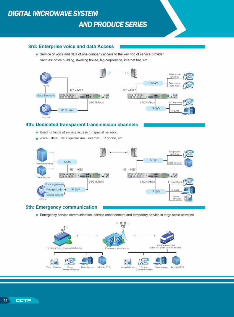
3rd: Enterprise voice and data Access
Service of voice and data of one company access to the key nod of service provider
Such as: office building, dwelling house, big corporation, internet bar, etc
4th: Dedicated transparent transmission channels
Used for kinds of service access for special network
voice、data、data special line、internet、IP phone, etc
5th: Emergency communication
Emergency service communication, service enhancement and temporary service in large scale activities
PSTN
Internet
34/34Mbps 34/34Mbps
IP Router
Voice Network
IP SW
RT/SW
4E1-16E1 4E1-16E1
Telephoneand Fax
Telephoneand Fax
IP Telephone
IP LAN
Telephone and Fax
IP Telephone
IP LAN
Video TerminalInternet
34/34Mbps 34/34Mbps
IP SW
MUX
IP voice gateway
Private LAN
Video serverIP SW
Data deviceTelephone switch
Data device
MUX
4E1-16E1 4E1-16E1
Voice Communications
Data Access Mobile BTSVideo Monitor Voice Communication
Data Access Mobile BTSVideo Monitor
Communication houseTemporary communication houseVehicle mounted
point-to-point communication
12
SUPER NETWORK MANAGEMENT
Main Interface Instruction
Other Function Instruction
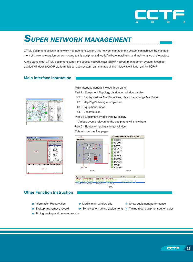
CT-ML equipment builds in a network management system, this network management system can achieve the manage-
ment of the remote equipment connecting to this equipment, Greatly facilitate installation and maintenance of the project.
At the same time, CT-ML equipment supply the special network class SNMP network management system; It can be
applied Windows2000/XP platform. It is an open system, can manage all the microwave link net unit by TCP/IP.
Information Preservation Modify main window title Show equipment performance
Backup and remove record Some system timing assignments Timing reset equipment button color
Timing backup and remove records
Main Interface general include three parts:
Part A : Equipment Topology distribution window display
(1) Display various MapPage titles, click it can change MapPage;
(2) MapPage’s background picture;
(3) Equipment Button;
(4) Decorate icon;
Part B : Equipment events window display
Various events relevant to the equipment will show here.
Part C : Equipment status monitor window
This window has five pages
PartA PartB
PartC

http://www.centron.com.cn
Add: Centron Communications Technologies Fujian Co.,Ltd. Xunmei, Quanzhou, Fujian, China.
Tel: +86-595-22882192/3 Fax: +86-595-22888954 http://www.centron.com.cn
Centron Communications Technologies Fujian Co.,Ltd.


![SOLENOID VALVES SERIES · 2013. 9. 3. · 600-4E2 1140 [40.21] A600-4E1 A603-4E2 600-4A2 A600-4A2 Mass 900 [31.75] Basic model 600-4E1 603-4E2 A600-4E2 600-4A A600-4A LM A (330×n)+640](https://img.dokumen.tips/doc/110x75/60af2ae20d9ab45ce563aca1/solenoid-valves-series-2013-9-3-600-4e2-1140-4021-a600-4e1-a603-4e2-600-4a2.jpg)