Embed Size (px)
Citation preview
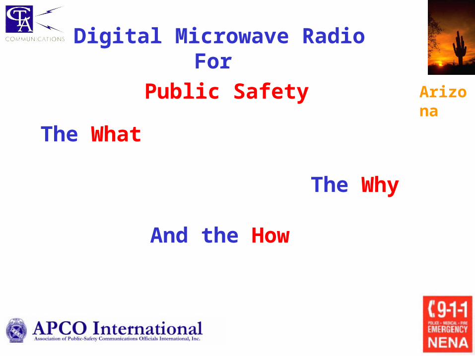
What is Microwave ?
•Point to Point Wireless – FCC Part 101
• Private, Secure & Hi-reliability
• Connectivity to 911 Center & Radio Sites
Voice &
Data
Voice &
Data
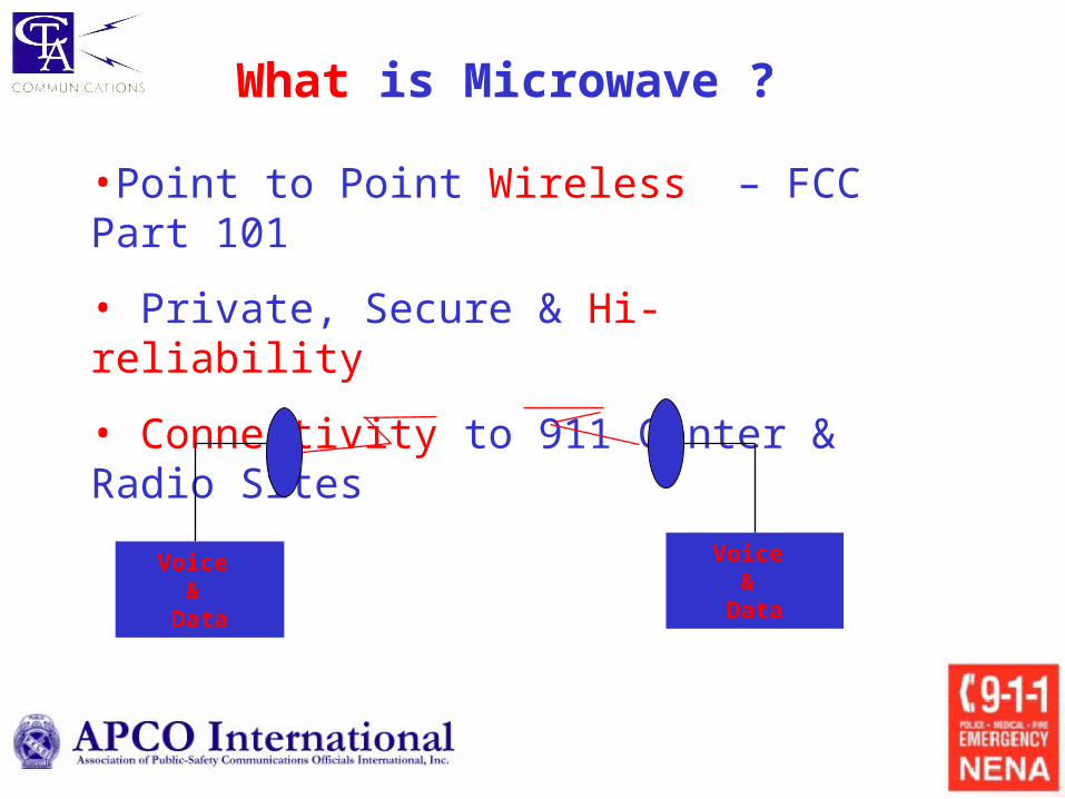
N.American Asynchronous Standards (Digital)
SignalType
Bit Rate(kbs)
No. ofChannels
Line CodeType
DSO
DS1
DS2
DS3
64
1,544
6,312
44,736
1
24
96
672
AMI
B8ZS AMI
B6ZS
B3ZS
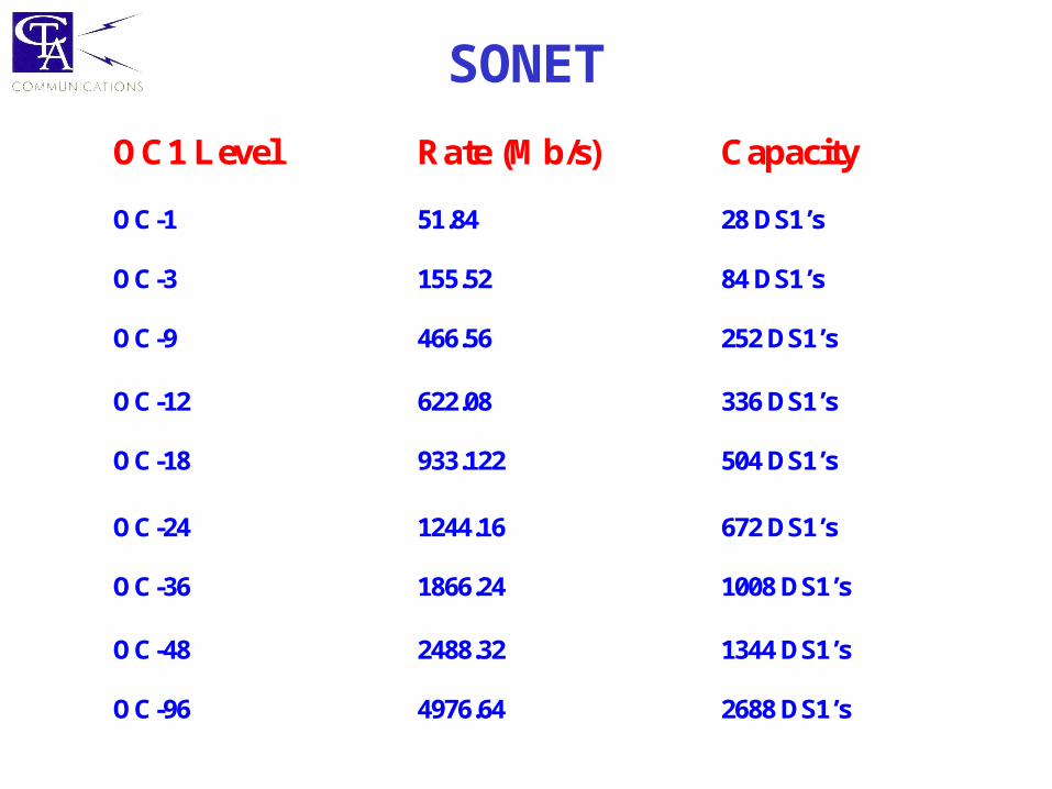
SONET
OC1 Level Rate (Mb/s) Capacity OC-1
51.84
28 DS1’s
OC-3 OC-9
155.52 466.56
84 DS1’s 252 DS1’s
OC-12 OC-18
622.08 933.122
336 DS1’s 504 DS1’s
OC-24 OC-36
1244.16 1866.24
672 DS1’s 1008 DS1’s
OC-48
2488.32
1344 DS1’s
OC-96 4976.64 2688 DS1’s
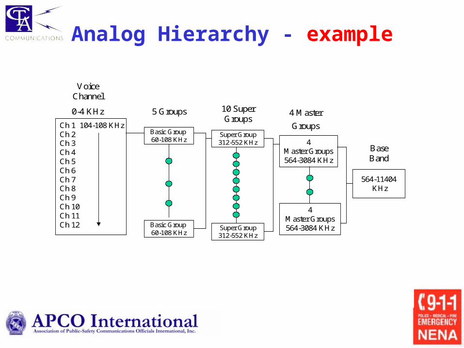
Analog Hierarchy - example
Ch 1 104-108 KHzCh 2 Ch 3 Ch 4Ch 5Ch 6Ch 7Ch 8Ch 9Ch 10Ch 11Ch 12
Voice Channel
0-4 KHz
Basic Group 60-108 KHz
Basic Group 60-108 KHz
5 Groups 10 Super Groups
Super Group312-552 KHz
Super Group312-552 KHz
4Master Groups564-3084 KHz
4Master Groups564-3084 KHz
564-11404KHz
4 Master
Groups
Base Band
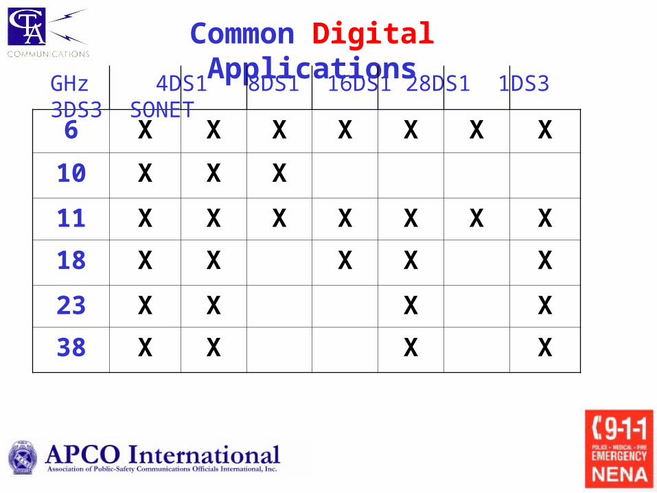
Common Digital Applications
6 X X X X X X X
10 X X X
11 X X X X X X X
18 X X X X X
23 X X X X
38 X X X X
GHz 4DS1 8DS1 16DS1 28DS1 1DS3 3DS3 SONET
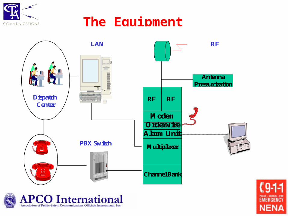
The Equipment
RF
Multiplexer
RF
Channel Bank
AntennaPressurization
RF
ModemOrderwire
Alarm Unit PBX Switch
Dispatch Center
LAN
Why microwave? System Performance
• Frequency Bands (FCC)
• Capacity Requirements
• Path Characteristics, length, terrain, climate
• System Reliability
• Radio Equipment Configurations
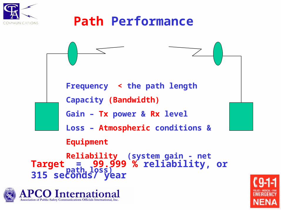
Path Performance
Frequency < the path length
Capacity (Bandwidth)
Gain – Tx power & Rx level
Loss – Atmospheric conditions & Equipment
Reliability (system gain - net path loss)
Target = 99.999 % reliability, or 315 seconds/ year
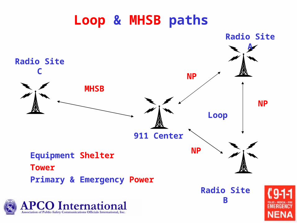
911 Center
Radio Site A
Loop & MHSB paths
Radio Site B
Radio Site C
Loop
MHSB
NP
NP
NPEquipment Shelter
Tower
Primary & Emergency Power
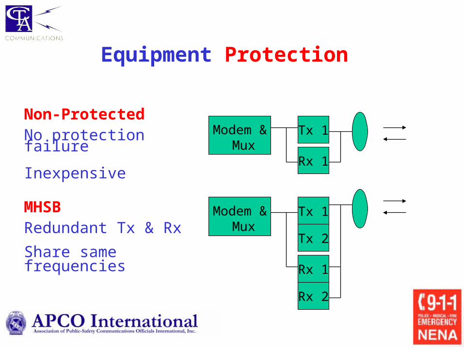
Equipment Protection
Tx 1
Rx 1
Modem & Mux
Tx 1
Tx 2
Rx 2
Rx 1
Modem & Mux
MHSBRedundant Tx & Rx
Share same frequencies
Non-ProtectedNo protection failure
Inexpensive
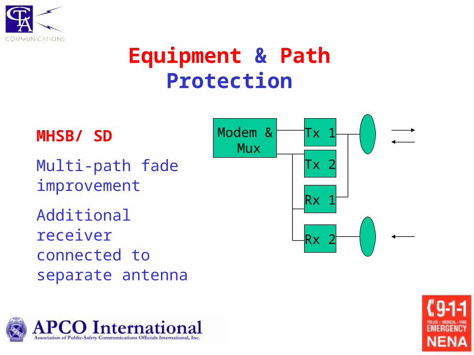
Equipment & Path Protection
Modem & Mux
Tx 1
Tx 2
Rx 2
Rx 1
MHSB/ SD
Multi-path fade improvement
Additional receiver connected to separate antenna
Tx 1
Rx 1
Modem & Mux
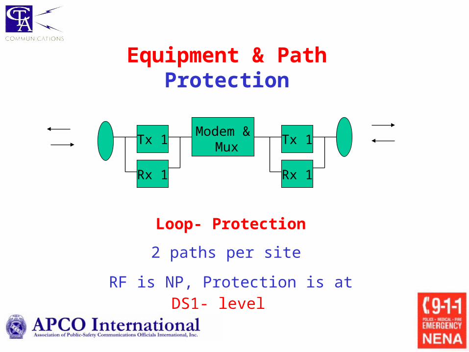
Loop- Protection
2 paths per site
RF is NP, Protection is at DS1- level
Tx 1
Rx 1
Equipment & Path Protection
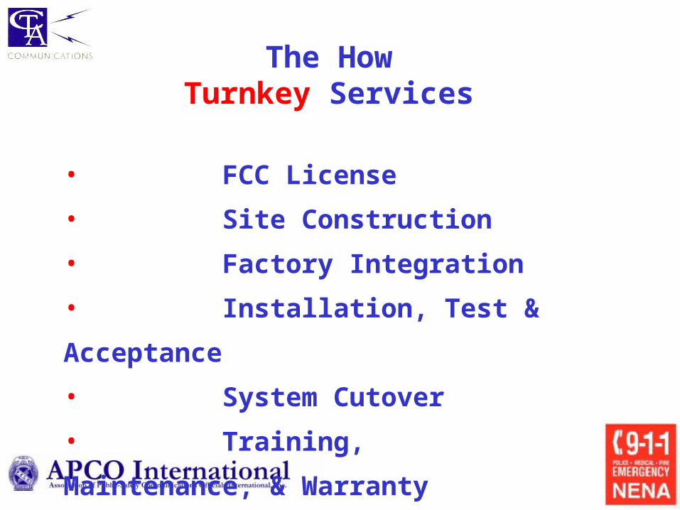
The HowTurnkey Services
• FCC License
• Site Construction
• Factory Integration
• Installation, Test & Acceptance
• System Cutover
• Training, Maintenance, & Warranty
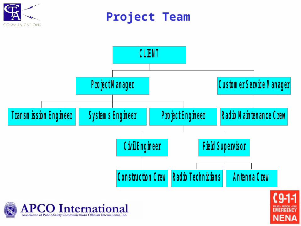
Project Team
Transm ission Engineer System s Engineer
Construction Crew
Civil Engineer
Radio Technicians Antenna Crew
Field Supervisor
Pro ject Engineer
Pro ject M anager
Radio M aintenance Crew
Custom er Service M anager
CLIENT
• Phase I System Definition
• Phase II Specifications Development
• Phase III Procurement Management
• Phase IV Implementation
• Phase V Acceptance
CTA – PROJECT APPROACH
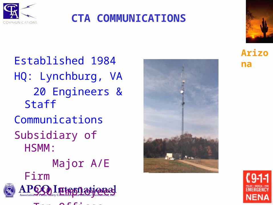
Arizona
CTA COMMUNICATIONS
Established 1984
HQ: Lynchburg, VA
20 Engineers & Staff
Communications
Subsidiary of HSMM:
Major A/E Firm
350 Employees
Ten Offices