Embed Size (px)
Citation preview

Digital Imaging and Communications in Medicine (DICOM)
Supplement 30: Waveform Interchange
DICOM Standards Committee, Working Group 1 - Cardiac and Vascular Information
1300 N. 17th Street, Suite 1847Rosslyn, Virginia 22209 USA
VERSION: Final Text
26 September 2000
DICOM Supplement 30 Waveform Interchange page ii
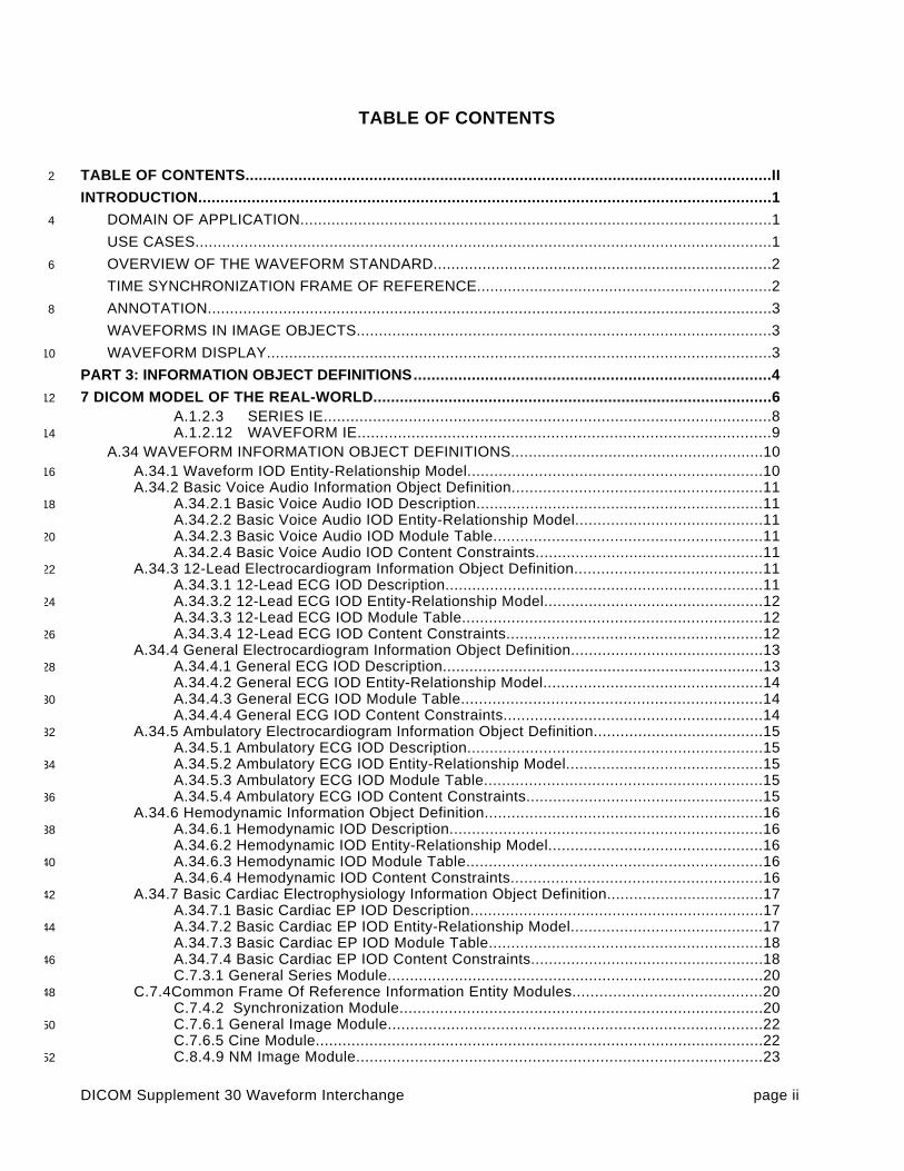
TABLE OF CONTENTS
TABLE OF CONTENTS.......................................................................................................................II2
INTRODUCTION.................................................................................................................................1
DOMAIN OF APPLICATION..........................................................................................................14
USE CASES.................................................................................................................................1
OVERVIEW OF THE WAVEFORM STANDARD............................................................................26
TIME SYNCHRONIZATION FRAME OF REFERENCE...................................................................2
ANNOTATION...............................................................................................................................38
WAVEFORMS IN IMAGE OBJECTS.............................................................................................3
WAVEFORM DISPLAY.................................................................................................................310
PART 3: INFORMATION OBJECT DEFINITIONS ................................................................................4
7 DICOM MODEL OF THE REAL-WORLD..........................................................................................612
A.1.2.3 SERIES IE....................................................................................................8A.1.2.12 WAVEFORM IE............................................................................................914
A.34 WAVEFORM INFORMATION OBJECT DEFINITIONS.........................................................10A.34.1 Waveform IOD Entity-Relationship Model..................................................................1016A.34.2 Basic Voice Audio Information Object Definition........................................................11
A.34.2.1 Basic Voice Audio IOD Description................................................................1118A.34.2.2 Basic Voice Audio IOD Entity-Relationship Model..........................................11A.34.2.3 Basic Voice Audio IOD Module Table............................................................1120A.34.2.4 Basic Voice Audio IOD Content Constraints...................................................11
A.34.3 12-Lead Electrocardiogram Information Object Definition..........................................1122A.34.3.1 12-Lead ECG IOD Description.......................................................................11A.34.3.2 12-Lead ECG IOD Entity-Relationship Model.................................................1224A.34.3.3 12-Lead ECG IOD Module Table...................................................................12A.34.3.4 12-Lead ECG IOD Content Constraints.........................................................1226
A.34.4 General Electrocardiogram Information Object Definition...........................................13A.34.4.1 General ECG IOD Description........................................................................1328A.34.4.2 General ECG IOD Entity-Relationship Model.................................................14A.34.4.3 General ECG IOD Module Table...................................................................1430A.34.4.4 General ECG IOD Content Constraints..........................................................14
A.34.5 Ambulatory Electrocardiogram Information Object Definition......................................1532A.34.5.1 Ambulatory ECG IOD Description..................................................................15A.34.5.2 Ambulatory ECG IOD Entity-Relationship Model............................................1534A.34.5.3 Ambulatory ECG IOD Module Table..............................................................15A.34.5.4 Ambulatory ECG IOD Content Constraints.....................................................1536
A.34.6 Hemodynamic Information Object Definition..............................................................16A.34.6.1 Hemodynamic IOD Description......................................................................1638A.34.6.2 Hemodynamic IOD Entity-Relationship Model................................................16A.34.6.3 Hemodynamic IOD Module Table..................................................................1640A.34.6.4 Hemodynamic IOD Content Constraints........................................................16
A.34.7 Basic Cardiac Electrophysiology Information Object Definition...................................1742A.34.7.1 Basic Cardiac EP IOD Description..................................................................17A.34.7.2 Basic Cardiac EP IOD Entity-Relationship Model...........................................1744A.34.7.3 Basic Cardiac EP IOD Module Table.............................................................18A.34.7.4 Basic Cardiac EP IOD Content Constraints....................................................1846C.7.3.1 General Series Module....................................................................................20
C.7.4Common Frame Of Reference Information Entity Modules..........................................2048C.7.4.2 Synchronization Module.................................................................................20C.7.6.1 General Image Module...................................................................................2250C.7.6.5 Cine Module....................................................................................................22C.8.4.9 NM Image Module..........................................................................................2352

DICOM Supplement 30 Waveform Interchange page iii
C.8.12.1 VL Image Module.........................................................................................23C.10 CURVE , GRAPHIC AND WAVEFORM ..............................................................................2454
C.10.8 Waveform Identification Module...............................................................................24C.10.9 Waveform Module....................................................................................................2556
C.10.9.1 Waveform Attribute Descriptions....................................................................27C.10.9.1.7 Waveform Data..........................................................................................3058
C.10.10 Waveform Annotation Module.................................................................................31C.10.10.1 Annotation Attribute Descriptions.................................................................3260F.3.2.2 DIRECTORY INFORMATION MODULE.......................................................34
F.4 BASIC DIRECTORY IOD INFORMATION MODEL.................................................................3462
F.5.24 Waveform Directory Record Definition........................................................................35ANNEX J - WAVEFORMS (INFORMATIVE)......................................................................................3664
J.1 DOMAIN OF APPLICATION..................................................................................................36
J.2 USE CASES.........................................................................................................................3666
J.3 TIME SYNCHRONIZATION FRAME OF REFERENCE...........................................................37
J.4 WAVEFORM ACQUISITION MODEL....................................................................................3768
J.5 WAVEFORM INFORMATION MODEL...................................................................................38
J.6 HARMONIZATION WITH HL7................................................................................................3970
J.6.1 HL7 Waveform Observation.........................................................................................39J.6.2 Channel Definition........................................................................................................4072J.6.3 Timing..........................................................................................................................40J.6.4 Waveform Data............................................................................................................4174J.6.5 Annotation...................................................................................................................41
J.7 HARMONIZATION WITH SCP-ECG.......................................................................................4176
PART 4: SERVICE CLASS SPECIFICATIONS ..................................................................................42
B.5 STANDARD SOP CLASSES................................................................................................4378
I.4 MEDIA STORAGE STANDARD SOP CLASSES...................................................................43
PART 5: DATA STRUCTURES AND ENCODING...............................................................................4480
7.5 NESTING OF DATA SETS....................................................................................................45
SECTION 8 ENCODING OF PIXEL, AND OVERLAY, AND WAVEFORM DATA..............................4682
8.1 PIXEL AND OVERLAY DATA, AND RELATED DATA ELEMENTS ........................................46
8.1 PIXEL AND OVERLAY DATA ENCODING OF RELATED DATA ELEMENTS ........................4684
8.1.1 Pixel data encoding of related data elements..............................................................468.3 WAVEFORM DATA AND RELATED DATA ELEMENTS ........................................................4686
A.1DICOM IMPLICIT VR LITTLE ENDIAN TRANSFER SYNTAX................................................47
A.2DICOM LITTLE ENDIAN TRANSFER SYNTAX (EXPLICIT VR)..............................................4788
A.3DICOM BIG ENDIAN TRANSFER SYNTAX (EXPLICIT VR)...................................................47
A.4TRANSFER SYNTAXES FOR ENCAPSULATION OF ENCODED PIXEL DATA.....................4890
PART 6: DATA DICTIONARY............................................................................................................49
6 REGISTRY OF DICOM DATA ELEMENTS..................................................................................5092
ANNEX A REGISTRY OF DICOM UNIQUE IDENTIFIERS (UID)....................................................52
ANNEX B – DICOM TERMINOLOGY MAPPING RESOURCE REGISTRY OF CONTEXT GROUPS AND94CONTROLLED TERMINOLOGY.......................................................................................................53
ANNEX C – REGISTRY OF TEMPLATES.........................................................................................6896
PART 11: MEDIA STORAGE APPLICATION PROFILES ..................................................................70
ANNEX X (NORMATIVE) - WAVEFORM DISKETTE INTERCHANGE PROFILE................................7198
X.1 PROFILE IDENTIFICATION..................................................................................................71
X.2 CLINICAL CONTEXT............................................................................................................7100
X.2.1 Roles and Service Class Options.................................................................................71

DICOM Supplement 30 Waveform Interchange page iv
X.4 STD-WVFM-ECG-FD PROFILE.............................................................................................7202
X.4.1 SOP Classes and Transfer Syntaxes...........................................................................72X.4.2 Physical Medium And Medium Format........................................................................7204X.4.3 Directory Information in DICOMDIR..............................................................................72
X.5 STD-WVFM-HD-FD PROFILE...............................................................................................7206
X.5.1 SOP Classes and Transfer Syntaxes...........................................................................72X.5.2 Physical Medium And Medium Format........................................................................7308X.5.3 Directory Information in DICOMDIR..............................................................................73

DICOM Supplement 30 Waveform Interchange page 1
Introduction10
DICOM Working Group 1 - Cardiac and Vascular Information has undertaken the work task to develop thisproposed DICOM Supplement to address the robust interchange of waveform and related data in DICOM.12This work primarily targets cardiology waveforms, including electrocardiographic and hemodynamic signals,but WG1 has endeavored to ensure it is applicable to a broad range of waveforms when acquired in a14medical imaging environment.
DOMAIN OF APPLICATION16
Waveform acquisition is part of both the medical imaging environment and the general clinical environment.Because of its broad use, there has been significant previous and complementary work in waveform18standardization of which WG1 has taken note:
ASTM E31.16 - E1467 Specification for Transferring Digital Neurophysiogical Data Between Independent20Computer Systems
CEN TC251 PT5-007 - prENV1064 draft Standard Communications Protocol for Computer-Assisted22Electrocardiography (SCP-ECG).
CEN TC251 PT5-021 - draft Vital Signs Information Representation Standard (VITAL)24
HL7 Automated Data SIG - HL7 Version 2.3, Chapter 7.14-20
IEEE P1073 - draft Medical Information Bus Standard (MIB)26
DICOM - NEMA PS3.3, Section A.10 Standalone Curve Information Object Definition
28
The domain of this Supplement is waveform acquisition within the imaging context. It is specifically meant toaddress waveform acquisitions which will be analyzed with other data which is transferred and managed using30the DICOM protocol. It allows the addition of waveform data to that context with minimal incremental cost.Further, it leverages the DICOM persistent object capability for maintaining referential relationships to other32data collected in a multi-modality environment, including references necessary for multi-modalitysynchronization.34
Waveform interchange in other clinical contexts may use different protocols more appropriate to thoseenvironments. In particular, HL7 may be used for transfer of waveform observations to general clinical36information systems, and MIB may be used for real-time physiological monitoring and therapy.
The waveform information object definition herein has been specifically harmonized at the semantic level with38the HL7 waveform message format. The use of a common object model allows straightforward transcodingand interoperation between systems that use DICOM for waveform interchange and those that use HL7, and40may be viewed as an example of common semantics implemented in the differing syntaxes of twomessaging systems.42
Note: HL7 allows transport of DICOM SOP Instances (information objects) encapsulated within HL7 messages.Since the DICOM and HL7 waveform semantics are harmonized, DICOM Waveform SOP Instances need not44be transported as encapsulated data, as they can be transcoded to native HL7 Waveform Observation format.
46
USE CASES
The following are specific use case examples for waveforms in the imaging environment.48
Case 1: Catheterization Laboratory - During a cardiac catheterization, several independent pieces of dataacquisition equipment may be brought together for the exam. An electrocardiographic subsystem records50surface ECG waveforms; an X-ray angiographic subsystem records motion images; a hemodynamicsubsystem records intracardiac pressures from a sensor on the catheter. These subsystems send their52

DICOM Supplement 30 Waveform Interchange page 2
acquired data by network to a repository. These data are assembled at an analytic workstation by retrievingfrom the repository. For a left ventriculographic procedure, the ECG is used by the physician to determine the54time of maximum and minimum ventricular fill, and when coordinated with the angiographic images, anaccurate estimate of the ejection fraction can be calculated. For a valvuloplasty procedure, the56hemodynamic waveforms are used to calculate the pre-intervention and post-intervention pressure gradients.
Case 2: Electrophysiology Laboratory - An electrophysiological exam will capture waveforms from multiple58
sensors on a catheter; the placement of the catheter in the heart is captured on an angiographic image. Atan analytic workstation, the exact location of the sensors can thus be aligned with a model of the heart, and60the relative timing of the arrival of the electrophysiological waves at different cardiac locations can bemapped.62
Case 3: Stress Exam - A stress exam may involve the acquisition of both ECG waveforms andechocardiographic ultrasound images from portable equipment at different stages of the test. The64waveforms and the echocardiograms are output on an interchange disk, which is then input and read at areview station. The physician analyzes both types of data to make a diagnosis of cardiac health.66
OVERVIEW OF THE WAVEFORM STANDARD
This Supplement was developed in accordance with the standard development process of the DICOM68Standards Committee. It includes changes to Parts 3, 4, 5, 6, and 11 of the DICOM Standard (NEMA PS3).
DICOM has had a rudimentary mechanism to interchange waveform data, the Curve Information Entity, used70within the Standalone Curve Information Object and within other composite image objects. This Supplementfollows the general approach of that capability, but refines it for the specific requirements of time-based72waveforms, and makes its syntax and semantics more robust.
The waveform information objects are generalization of the class of DICOM composite image information74objects. The hierarchical structure of patient/study/series/object instances, represented by the canonicalDICOM image information model, is unchanged. The changes to Part 3 of the DICOM Standard include76modification of the Composite Image Information Model to include waveforms as well as pixel data, and aninformative annex describing the waveform data model.78
Digitization of waveform samples is defined within this proposal using linear scales, using 8- or 16-bit integerquantities. Provision has also been made for µ-law and A-law non-linear scaled data for audio data, as80defined in ITU-T Recommendation G.711.
Note that in DICOM communications, compression is selected at the time of data transfer by negotiating a82Transfer Syntax; a compressed Transfer Syntax for waveform data is thus independent of the waveforminformation object definition specified in this Supplement. While such a compressed waveform Transfer84Syntax has not been proposed, that is an area for future work complementing this Supplement. In themeantime, the various uncompressed Transfer Syntaxes are available for waveforms (see DICOM Part 5).86
The syntax proposed for waveform structures differs from data elements currently defined within the CurveInformation Entity. In developing the Waveform definition, WG1 had the option of continuing the use of88Repeating Groups (see DICOM Part 5, Section 7.6) for the syntax of curves, or of moving to the construct ofSequences. The latter approach was adopted based on an explicit intent stated in Part 5 to move away from90Repeating Groups.
TIME SYNCHRONIZATION FRAME OF REFERENCE92
Synchronization of acquisition across multiple modalities in a single study (e.g., angiography andelectrocardiography) requires either a shared trigger, or a shared clock. This Supplement proposes a94Synchronization Module within the Frame of Reference Information Entity to specify the synchronizationmechanism. A common temporal environment used by multiple equipment is identified by a shared96Synchronization Frame of Reference UID. How this UID is determined and distributed to the participatingequipment is outside the scope of the standard.98
The method used for time synchronization of equipment clocks is implementation or site specific, andtherefore outside the scope of this proposal. If required, standard time distribution protocols are available00(e.g., NTP, IRIG, GPS).

DICOM Supplement 30 Waveform Interchange page 3
An informative description of time distribution methods can be found at:02http://www.bancomm.com/cntpApp.htm
A second method of synchronizing acquisitions is to utilize a common reference channel (temporal fiducial),04which is recorded in the data acquired from the several equipment units participating in a study, and/or whichis used to trigger synchronized data acquisitions. For instance, the “X-ray on” pulse train which triggers the06acquisition of frames for an X-ray angiographic SOP Instance can be recorded as a waveform channel in asimultaneously acquired hemodynamic waveform SOP Instance, and can be used to align the different08object instances. Associated with this Supplement are proposed coded entry channel identifiers to specificallysupport this synchronization mechanism (DICOM Terminology Mapping Resource Context Group ID 3090).10
ANNOTATION
WG1 has identified a common clinical use for waveform annotations. These annotations are typically12generated automatically as part of the data acquisition, such as waveform maxima and minima (peakdetection), or labeling of particular stimuli. These annotations are considered an integral to the presentation14(display) of waveforms.
Within the current DICOM image information object data model there are two basic mechanisms for16annotating an image, especially to describe a Region Of Interest (ROI) - overlays and outline curves.However, these mechanisms operate at the display, rather than the semantic, level. Since waveform display18is not specified in this Supplement, overlays are not an appropriate annotation construct.
This Supplement therefore introduces a new Waveform Annotation Module, which may be carried within the20composite waveform information objects. The annotation is fundamentally a label, with a pointer to the ROI inthe waveform. ROI references are provided for waveforms down to individual samples, and for absolute or22relative temporal ROIs.
The format of annotation is consistent with that of Structured Report observations proposed in DICOM24Supplement 23 - Structured Reporting. Labels may be textual; alternatively, annotations may make use ofcoded entries instead of text, with appropriate controlled vocabulary lists. The coded entry will describe the26semantic concept carried by the label. In addition to the label concept, a quantitative value for that attributecan be specified in a numeric field, or a qualitative value can be specified using a controlled vocabulary in an28associated coded entry.
WAVEFORMS IN IMAGE OBJECTS30
In general, in DICOM an object is of a single modality. However, DICOM does allow object instances whichinclude both image and curve data. In this case, the curve data is considered ancillary to the image data; so,32for instance, the modality attribute will indicate the imaging modality.
Although the Waveform Module defined in this Supplement facilitates the update of IODs to allow use of the34Waveform Module, rather than the Curve Module, to handle waveforms in image objects, such updates arenot part of this Supplement. Such changes would require a new SOP Class UID for the objects of the36updated definition, and are thus in the purview of the Working Groups responsible for the IODs of the variousmodalities.38
WAVEFORM DISPLAY
How a workstation displays or processes data objects has generally been beyond the scope of the DICOM40standard. In the current case, the waveform object carries the raw waveform sample data only, it does notspecify how the waveforms are to be displayed. Determining an appropriate display is left to the ingenuity42and innovation of manufacturers, who must take into account their knowledge of the clinical environment andeffective user interfaces.44

DICOM Supplement 30 Waveform Interchange page 4
46
48
50
Changes to:52
NEMA Standards Publication PS 3.3-1999
Digital Imaging and Communications in Medicine (DICOM)54
Part 3: Information Object Definitions
56

DICOM Supplement 30 Waveform Interchange page 5
58
1. Add item to Section 2 Normative References
60
ITU-T Recommendation G.711 (1988) - Pulse code modulation (PCM) of voice frequencies
62
DICOM Supplement 30 Waveform Interchange page 6
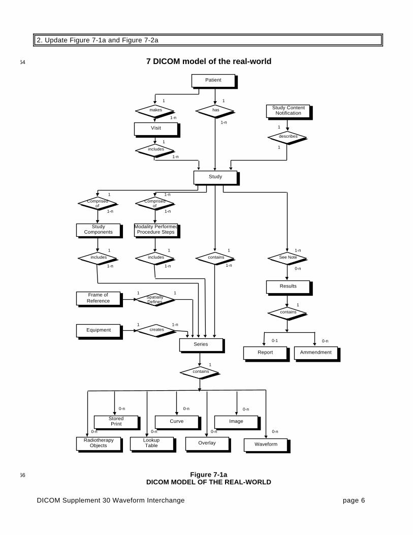
2. Update Figure 7-1a and Figure 7-2a
7 DICOM model of the real-world64
Patient
Visit
Study
Study ContentNotification
makes has
describes
includes
StudyComponents
Modality PerformedProcedure Steps
Comprisedof
Comprisedof
includes includes contains See Note
Results
contains
Report
LookupTable
StoredPrint
RadiotherapyObjects
1-n
1
0-n
1
1-n
1
1
1-n1
1
1-n
1-n
1-n
1 1 1
0-n
0-n0-n
1-n
0-n
1
0-1
0-n
Series
Frame ofReference
creates
SpatiallyDefines
Equipment
1-n 1-n 1-n
1
1-n
1
1
Curve
Overlay
0-n
Image
Ammendment
0-n
contains
1
Waveform
0-n
Figure 7-1a66DICOM MODEL OF THE REAL-WORLD

DICOM Supplement 30 Waveform Interchange page 7
Patient IOD
Visit IOD
Study IOD
Basic StudyDescriptor IOD
references references
describes
references
Study ComponentIOD
Modality PerformedProc. Step IOD
Comprisedof
Comprisedof
references references references
Image IOD
Standalone CurveIOD
StandaloneOverlay IOD
StandaloneModality LUT IOD
Standalone VOILUT IOD
Stored Print IODSee Figure 7.2b
Radiotherapy IODsSee Figure 7.2c
1-n
1
0-n
1
1-n
1
1
1-n1
1
1-n
1-n
1-n
1 1 1
0-n 0-n
0-n0-n0-n
See Note
Results IOD
references
Interpretation IOD
1-n
0-n
1
0-n
0-n
Waveform IOD
0-n
68
Figure 7-2aDICOM INFORMATION MODEL70
72

DICOM Supplement 30 Waveform Interchange page 8
3. Add waveform IE to Figure A.1-1
74
Patient
issubject
of
Study
contains
Seriesspatially ortemporally
definescreates
Frame of ReferenceEquipment
Image(Pixels)
1
0,n
1,n
1,n
Curve Overlay VOILUT
ModalityLUT
0,n 0,n 0,n0,1
0,n
1
1,n1
1
contains
1
Waveform
0,n
Figure A.1-176DICOM Composite Image IOD Information Model
78
4. Modify section A.1.2.3 Series IE
A.1.2.3SERIES IE80
The Series IE defines the Attributes which are used to group images, presentation states, overlays and/orcurves composite instances into distinct logical sets. Each series is associated with exactly one Study.82
The following criteria groups images composite instances into a specific series:
a. All composite instances within a series must be of the same modality84
b. If a specific Composite Instance IOD specifies the support of a Frame of Reference IE, all compositeinstances within the series shall be spatially or temporally related to each other; therefore, each series86
is associated with exactly one Frame of Reference IEc. If a specific Composite Instance IOD specifies the support of the Equipment IE, all composite88
instances within the series shall be created by the same equipment; therefore, each series isassociated with exactly one Equipment IE90
d. All composite instances within a series shall have the same series information92
Overlays and Curves may be grouped into a Series with or without Images. The Equipment IE and Frame ofReference IE are irrelevant to the Overlay IE and Curve IE.94
Presentation States shall be grouped into Series without Images (i.e. in a different Series from the Seriescontaining the Images to which they refer). The Frame of Reference IE is irrelevant to the Presentation State96IE.

DICOM Supplement 30 Waveform Interchange page 9
Note: The Series containing Presentation States and the Series containing the Images to which they refer are both98contained within the same Study.
Waveforms shall be grouped into Series without Images. A Frame of Reference IE may apply to both00
Waveform Series and Image Series.
02
5. Add section A.1.2.12 Waveform IE04
A.1.2.12 WAVEFORM IE
The Waveform IE represents a multi-channel time-based digitized waveform. The waveform consists of06measurements of some physical qualities (e.g., electrical voltage, pressure, gas concentration, or sound),sampled at constant time intervals. The measured qualities may originate, for example, in any of the following08sources:
a. the anatomy of the patient,10
b. therapeutic equipment (e.g., a cardiac pacing signal or a radio frequency ablation signal),c. equipment for diagnostic synchronization (e.g., a clock or timing signal used between distinct12
devices),d. the physician’s voice (e.g., a dictated report).14
The sample data within a Waveform IE may represent one or more acquired channels. Several signal16channels acquired at the same sampling rate can be multiplexed (by interleaving samples) in a singlemultiplex group. (See also Annex J.)18
20
6. Modify Table A.1-1 to add Waveform Object column and Synchronization Module and Waveform Modulerows22
Specific change to add Waveform Objects columns and Synchronization Module and Waveform24Identification, Waveform and Waveform Annotation Module rows to the Composite Information ObjectModules Overview table left to the discretion of the DICOM Standards Editor.26

DICOM Supplement 30 Waveform Interchange page 10
7. Add Section A.34 to provide IODs for various waveform objects28
A.34 WAVEFORM INFORMATION OBJECT DEFINITIONS
A.34.1 Waveform IOD Entity-Relationship Model30
The Waveform E-R Model is shown in Figure A.34-1. This model applies to a variety of Waveform IODs.
Patient
issubject
of
Study
contains
Seriestemporally
definescreates
Frame of ReferenceEquipment
1
1,n
1,n
0,n
1
1,n1
1
contains
1
Waveform
1,n
32
Figure A.34-1DICOM Waveform IOD Information Model34
36

DICOM Supplement 30 Waveform Interchange page 11
A.34.2 Basic Voice Audio Information Object Definition38
A.34.2.1 Basic Voice Audio IOD Description
The Basic Voice Audio IOD is the specification of a digitized sound which has been acquired or created by an40audio modality or by an audio acquisition function within an imaging modality. A typical use is reportdictation.42
A.34.2.2 Basic Voice Audio IOD Entity-Relationship Model
The E-R Model in Section A.34.1 of this Part applies to the Basic Voice Audio IOD.44
A.34.2.3 Basic Voice Audio IOD Module Table
Table A.34.2-146Basic Voice Audio IOD Modules
IE Module Reference Usage
Patient Patient C.7.1.1 M
Study General Study C.7.2.1 M
Patient Study C.7.2.2 U
Series General Series C.7.3.1 M
Frame ofReference
Synchronization C.7.4.2 U
Equipment General Equipment C.7.5.1 M
Waveform Waveform Identification C.10.8 M
Waveform C.10.9 M
Acquisition Context C.7.6.14 M
Waveform Annotation C.10.10 U
SOP Common C.12.1 M48
A.34.2.4 Basic Voice Audio IOD Content Constraints
A.34.2.4.1 Modality50
The value of Modality (0008,0060) shall be AU.
A.34.2.4.2 Waveform Sequence52
The number of Waveform Sequence (5400,0100) Items shall be one.
A.34.2.4.3 Number of Waveform Channels54
The value of the Number of Waveform Channels (003A,0005) in the Waveform Sequence Item shall be 1 or2.56
A.34.2.4.4 Sampling Frequency
The value of the Sampling Frequency (003A,001A) in the Waveform Sequence Item shall be 8000.58
A.34.2.4.5 Waveform Sample Interpretation
The value of the Waveform Sample Interpretation (5400,1006) in the Waveform Sequence Item shall be UB,60MB, or AB.
62
A.34.3 12-Lead Electrocardiogram Information Object Definition
A.34.3.1 12-Lead ECG IOD Description64
The 12-Lead Electrocardiogram (12-Lead ECG) IOD is the specification of digitized electrical signals from thepatient cardiac conduction system collected on the body surface, which has been acquired by an ECG66modality or by an ECG acquisition function within an imaging modality.

DICOM Supplement 30 Waveform Interchange page 12
A.34.3.2 12-Lead ECG IOD Entity-Relationship Model68
The E-R Model in Section A.34.1 of this Part applies to the 12-Lead ECG IOD.
A.34.3.3 12-Lead ECG IOD Module Table70
Table A.34.3-112-Lead ECG IOD Modules72
IE Module Reference Usage
Patient Patient C.7.1.1 M
Study General Study C.7.2.1 M
Patient Study C.7.2.2 U
Series General Series C.7.3.1 M
Frame ofReference
Synchronization C.7.4.2 U
Equipment General Equipment C.7.5.1 M
Waveform Waveform Identification C.10.8 M
Waveform C.10.9 M
Acquisition Context C.7.6.14 M
Waveform Annotation C.10.10 C – required if annotationis present
SOP Common C.12.1 M
A.34.3.4 12-Lead ECG IOD Content Constraints74
A.34.3.4.1 Modality
The value of Modality (0008,0060) shall be ECG.76
A.34.3.4.2 Acquisition Context Module
For SOP Instances of ECG acquired in the cardiac catheterization lab, the Defined Template for Acquisition78Context Sequence (0040,0555) is TID 3403. For routine resting or stress ECG, the Defined Template forAcquisition Context Sequence (0040,0555) is TID 3401.80
A.34.3.4.3 Waveform Sequence
The number of Waveform Sequence (5400,0100) Items shall be between 1 and 5, inclusive.82
A.34.3.4.4 Number of Waveform Channels
The value of the Number of Waveform Channels (003A,0005) in each Waveform Sequence Item shall be84between 1 and 13, inclusive. The total number of channels encoded across all Items shall not exceed 13.
Note: This specialization provides for up to five Waveform Sequence Items (multiplex groups), with a total of 1386channels. This allows, for instance, encoding of four sets of three simultaneously recorded channels, the setsbeing acquired sequentially, plus one continuous channel for the duration of the other sets. This can be used88to emulate the behavior of classical 12-lead ECG strip chart recorders with 4x3 presentation, plus a continuouslead II recording (see figure).90

DICOM Supplement 30 Waveform Interchange page 13
Multiplex Group 1 – leads I, II, III; time offset 0; duration 2.5 s92Multiplex Group 2 – leads aVR, aVL, aVF; time offset 2.5 s; duration 2.5 sMultiplex Group 3 – leads V1, V2, V3; time offset 5.0 s; duration 2.5 s94Multiplex Group 4 – leads V4, V5, V6; time offset 7.5 s; duration 2.5 sMultiplex Group 5 – lead II; time offset 0; duration 9.84 s96
FIGURE A.34.3-1 12-Lead ECG Example (Informative)
98
A.34.3.4.5 Number of Waveform Samples
The value of the Number of Waveform Samples (003A,0010) in each Waveform Sequence Item shall be less00than or equal to 16384.
Note: This allows over 16 seconds per channel at the maximum sampling frequency; if longer recordings are required,02the General ECG IOD may be used.
A.34.3.4.6 Sampling Frequency04
The value of the Sampling Frequency (003A,001A) in each Waveform Sequence Item shall be between 200and 1000, inclusive.06
A.34.3.4.7 Channel Source
The Baseline Context ID for the Channel Source Sequence (003A,0208) in each Channel Definition08Sequence Item shall be CID 3001.
A.34.3.4.8 Waveform Sample Interpretation10
The value of the Waveform Sample Interpretation (5400,1006) in each Waveform Sequence Item shall beSS.12
A.34.3.4.9 Waveform Annotation Module
The Defined Context ID for the Concept Name Code Sequence (0040,A043) in the Waveform Annotation14Sequence (0040,B020) shall be CID 3335. This Context Group supports the annotation of suppressedpacemaker spikes in the ECG waveform.16
A.34.4 General Electrocardiogram Information Object Definition
A.34.4.1 General ECG IOD Description18
The General Electrocardiogram (ECG) IOD is the specification of digitized electrical signals from the patientcardiac conduction system collected on the body surface, which has been acquired by an ECG modality or by20an ECG acquisition function within an imaging modality.

DICOM Supplement 30 Waveform Interchange page 14
A.34.4.2 General ECG IOD Entity-Relationship Model22
The E-R Model in Section A.34.1 of this Part applies to the General ECG IOD.
A.34.4.3 General ECG IOD Module Table24
Table A.34.4-1General ECG IOD Modules26
IE Module Reference Usage
Patient Patient C.7.1.1 M
Study General Study C.7.2.1 M
Patient Study C.7.2.2 U
Series General Series C.7.3.1 M
Frame ofReference
Synchronization C.7.4.2 U
Equipment General Equipment C.7.5.1 M
Waveform Waveform Identification C.10.8 M
Waveform C.10.9 M
Acquisition Context C.7.6.14 M
Waveform Annotation C.10.10 C – required if annotationis present
SOP Common C.12.1 M
A.34.4.4 General ECG IOD Content Constraints28
A.34.4.4.1 Modality
The value of Modality (0008,0060) shall be ECG.30
A.34.4.4.2 Waveform Sequence
The number of Waveform Sequence (5400,0100) Items shall be between 1 and 4, inclusive.32
A.34.4.4.3 Number of Waveform Channels
The value of the Number of Waveform Channels (003A,0005) in each Waveform Sequence Item shall be34between 1 and 24, inclusive.
A.34.4.4.4 Sampling Frequency36
The value of the Sampling Frequency (003A,001A) in each Waveform Sequence Item shall be between 200and 1000, inclusive.38
A.34.4.4.5 Channel Source
The Defined Context ID for the Channel Source Sequence (003A,0208) in each Channel Definition Sequence40Item shall be CID 3001.
Note: Terms from other Context Groups may also be used for extended specification of the Channel Source, as42declared in the Conformance Statement for an application (see PS3.2).
A.34.4.4.6 Waveform Sample Interpretation44
The value of the Waveform Sample Interpretation (5400,1006) in each Waveform Sequence Item shall beSS.46
A.34.4.4.7 Waveform Annotation Module
The Defined Context ID for the Concept Name Code Sequence (0040,A043) in the Waveform Annotation48Sequence (0040,B020) shall be CID 3335. This Context Group supports the annotation of suppressedpacemaker spikes in the ECG waveform.50

DICOM Supplement 30 Waveform Interchange page 15
A.34.5 Ambulatory Electrocardiogram Information Object Definition52
A.34.5.1 Ambulatory ECG IOD Description
The Ambulatory Electrocardiogram (ECG) IOD is the specification of digitized electrical signals from the54patient cardiac conduction system collected on the body surface, which has been acquired by an ambulatoryelectrocardiography (Holter) device.56
Note: The duration of acquisition represented in one SOP Instance is not specifically constrained, and is limited onlyby the maximum size of the Waveform Data attribute.58
A.34.5.2 Ambulatory ECG IOD Entity-Relationship Model
The E-R Model in Section A.34.1 of this Part applies to the Ambulatory ECG IOD.60
A.34.5.3 Ambulatory ECG IOD Module Table
Table A.34.5-162Ambulatory ECG IOD Modules
IE Module Reference Usage
Patient Patient C.7.1.1 M
Study General Study C.7.2.1 M
Patient Study C.7.2.2 U
Series General Series C.7.3.1 M
Frame ofReference
Synchronization C.7.4.2 U
Equipment General Equipment C.7.5.1 M
Waveform Waveform Identification C.10.8 M
Waveform C.10.9 M
Acquisition Context C.7.6.14 U
Waveform Annotation C.10.10 C – required if annotationis present
SOP Common C.12.1 M64
A.34.5.4 Ambulatory ECG IOD Content Constraints
A.34.5.4.1 Modality66
The value of Modality (0008,0060) shall be ECG.
A.34.5.4.2 Waveform Sequence68
The number of Waveform Sequence (5400,0100) Items shall be be 1.
A.34.5.4.3 Number of Waveform Channels70
The value of the Number of Waveform Channels (003A,0005) in the Waveform Sequence Item shall bebetween 1 and 12, inclusive.72
A.34.5.4.5 Sampling Frequency
The value of the Sampling Frequency (003A,001A) in each Waveform Sequence Item shall be between 5074and 1000, inclusive.
A.34.5.4.6 Channel Source76
The Defined Context ID for the Channel Source Sequence (003A,0208) in each Channel Definition SequenceItem shall be CID 3001.78
A.34.5.4.7 Waveform Sample Interpretation
The value of the Waveform Sample Interpretation (5400,1006) in each Waveform Sequence Item shall be80SB or SS.

DICOM Supplement 30 Waveform Interchange page 16
82
A.34.6 Hemodynamic Information Object Definition
A.34.6.1 Hemodynamic IOD Description84
The Hemodynamic IOD is the specification of digitized pressure, electrical, and other signals from the patientcirculatory system, which has been acquired by a hemodynamic modality.86
Note: The duration of acquisition represented in one SOP Instance is not specifically constrained, and is limited onlyby the maximum size of the Waveform Data attribute.88
A.34.6.2 Hemodynamic IOD Entity-Relationship Model
The E-R Model in Section A.34.1 of this Part applies to the Hemodynamic IOD.90
A.34.6.3 Hemodynamic IOD Module Table
Table A.34.6-192Hemodynamic IOD Modules
IE Module Reference Usage
Patient Patient C.7.1.1 M
Study General Study C.7.2.1 M
Patient Study C.7.2.2 U
Series General Series C.7.3.1 M
Frame ofReference
Synchronization C.7.4.2 C – Required if WaveformOriginality (003A,0004) isORIGINAL; may bepresent otherwise
Equipment General Equipment C.7.5.1 M
Waveform Waveform Identification C.10.8 M
Waveform C.10.9 M
Acquisition Context C.7.6.14 M
Waveform Annotation C.10.10 C – required if annotationis present
SOP Common C.12.1 M94
A.34.6.4 Hemodynamic IOD Content Constraints
A.34.6.4.1 Modality96
The value of Modality (0008,0060) shall be HD.
A.34.6.4.2 Acquisition Context Module98
The Defined Template for Acquisition Context Sequence (0040,0555) is TID 3403.
A.34.6.4.3 Waveform Sequence00
The number of Waveform Sequence (5400,0100) Items shall be between 1 and 4, inclusive.
A.34.6.4.4 Number of Waveform Channels02
The value of the Number of Waveform Channels (003A,0005) in each Waveform Sequence Item shall bebetween 1 and 8, inclusive.04
A.34.6.4.5 Sampling Frequency
The value of the Sampling Frequency (003A,001A) in each Waveform Sequence Item shall be less than or06equal to 400.

DICOM Supplement 30 Waveform Interchange page 17
A.34.6.4.7 Channel Source08
The Defined Context ID for the Channel Source Sequence (003A,0208) in each Channel Definition SequenceItem shall be CID 3003, CID 3001 for surface ECG channels, or CID 3090 for time synchronization channels.10The Channel Source Code Value shall encode at minimum the metric (measured physical quality) andfunction (measurement or stimulus); unless otherwise specifically encoded, the default function shall be12“measurement”.
The Channel Source Modifiers Sequence (003A,0209) in each Channel Definition Sequence Item shall be14used to specify additional qualifiers of the semantics of the waveform source, including technique andanatomic location, if not encoded by the Channel Source Code Value. Technique, with terms from Defined16Context ID 3241, shall be specified in Channel Source Modifiers Sequence Items prior to the cardiacanatomic location(s), with terms from Defined Context ID 3010, 3014, and 3019. If technique is pullback, the18sequence of anatomic locations shall be specified in ordered Channel Source Modifiers Sequence Items(e.g., initial, transitional, and final locations).20
Note: Terms from other Context Groups may also be used for extended specification of the Channel Source, asdeclared in the Conformance Statement for an application (see PS3.2).22
A.34.6.4.8 Waveform Sample Interpretation
The value of the Waveform Sample Interpretation (5400,1006) in each Waveform Sequence Item shall be24SS.
A.34.6.4.9 Waveform Annotation Module26
The Defined Context ID for the Concept Name Code Sequence (0040,A043) in the Waveform AnnotationSequence (0040,B020) shall be CID 3337.28
A.34.7 Basic Cardiac Electrophysiology Information Object Definition30
A.34.7.1 Basic Cardiac EP IOD Description
The Basic Cardiac Electrophysiology IOD is the specification of digitized electrical signals from the patient32cardiac conduction system collected in the heart, which has been acquired by an EP modality.
Note: The duration of acquisition represented in one SOP Instance is not specifically constrained, and is limited only34by the maximum size of the Waveform Data attribute.
A.34.7.2 Basic Cardiac EP IOD Entity-Relationship Model36
The E-R Model in Section A.34.1 of this Part applies to the Cardiac EP IOD.

DICOM Supplement 30 Waveform Interchange page 18
A.34.7.3 Basic Cardiac EP IOD Module Table38
Table A.34.7-1Basic Cardiac EP IOD Modules40
IE Module Reference Usage
Patient Patient C.7.1.1 M
Study General Study C.7.2.1 M
Patient Study C.7.2.2 U
Series General Series C.7.3.1 M
Frame ofReference
Synchronization C.7.4.2 C – Required if WaveformOriginality (003A,0004)value is ORIGINAL; maybe present otherwise
Equipment General Equipment C.7.5.1 M
Waveform Waveform Identification C.10.8 M
Waveform C.10.9 M
Acquisition Context C.7.6.14 M
Waveform Annotation C.10.10 C – required if annotationis present
SOP Common C.12.1 M
A.34.7.4 Basic Cardiac EP IOD Content Constraints42
A.34.7.4.1 Modality
The value of Modality (0008,0060) shall be EPS.44
A.34.7.4.2 Acquisition Context Module
The Defined Template for Acquisition Context Sequence (0040,0555) is TID 3450.46
A.34.7.4.3 Waveform Sequence
The number of Waveform Sequence (5400,0100) Items shall be between 1 and 4, inclusive.48
A.34.7.4.4 Sampling Frequency
The value of the Sampling Frequency (003A,001A) in each Waveform Sequence Item shall be less than or50equal to 2000.
A.34.7.4.5 Channel Source52
The Defined Context ID for the Channel Source Sequence (003A,0208) in each Channel Definition SequenceItem shall be CID 3011. The Channel Source Code Value shall encode at minimum the anatomic location of54the channel source.
The Channel Source Modifiers Sequence (003A,0209) in each Channel Definition Sequence Item shall be56used to specify additional qualifiers of the semantics of the waveform source, including metric (measuredphysical quality), function (measurement or stimulus), and technique from Defined Context ID 3240, and58anatomic location qualifiers from Defined Context ID 3019, if not encoded by the Channel Source CodeValue. If not explicitly encoded, the default metric and function shall be “voltage measurement”. If a60differential signal is used, that shall be indicated in a Modifier Item, and the positive pole and negative poleidentified in the subsequent two modifiers.62
Notes:1. Terms from other Context Groups may also be used for extended specification of the Channel Source, as64
declared in the Conformance Statement for an application (see PS3.2).2. A differential signal from the high right atrium , where electrode 1 on the catheter is the positive pole and66
electrode 3 the negative pole, could be specified by coded terms meaning:Channel Source: “High Right Atrium”68

DICOM Supplement 30 Waveform Interchange page 19
Channel Source Modifiers: “Differential”, “E1”, “E3”(Implicit default modifier: “Voltage Measurement”)70
A.34.7.4.6 Waveform Sample Interpretation72
The value of the Waveform Sample Interpretation (5400,1006) in each Waveform Sequence Item shall beSS.74
A.34.7.4.7 Waveform Annotation Module
The Defined Context ID for the Concept Name Code Sequence (0040,A043) in the Waveform Annotation76Sequence (0040,B020) shall be CID 3339.
78
DICOM Supplement 30 Waveform Interchange page 20
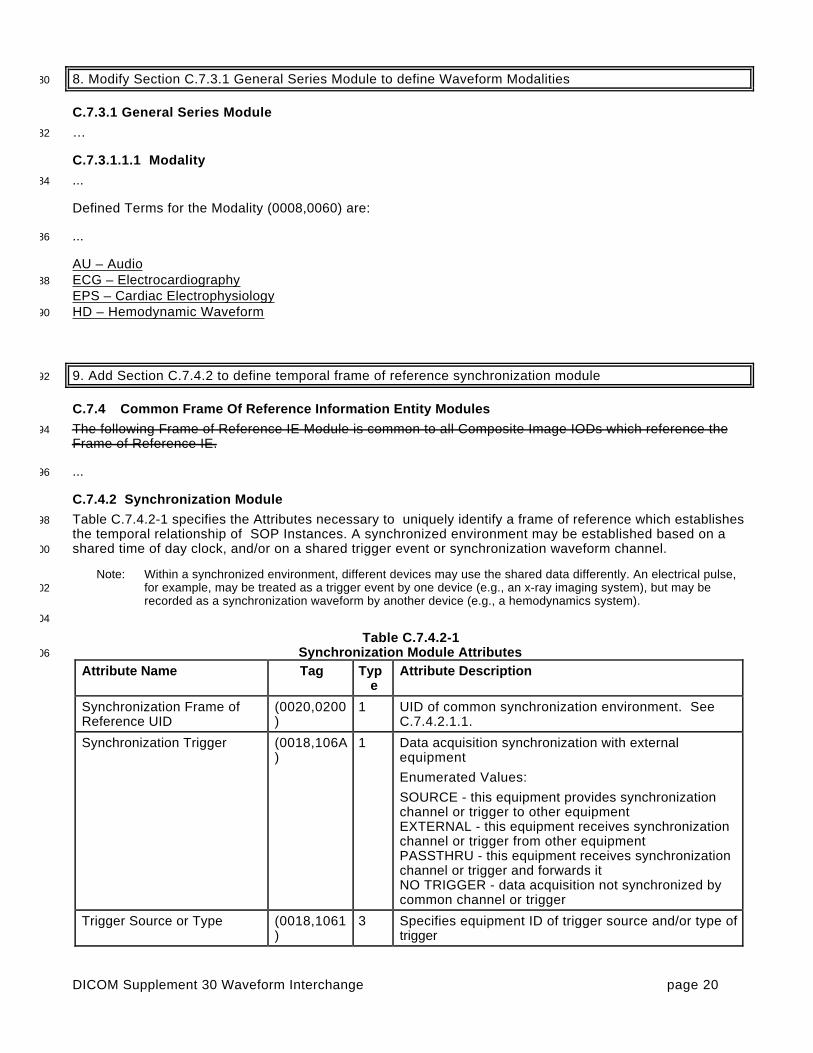
8. Modify Section C.7.3.1 General Series Module to define Waveform Modalities80
C.7.3.1 General Series Module
…82
C.7.3.1.1.1 Modality
...84
Defined Terms for the Modality (0008,0060) are:
...86
AU – AudioECG – Electrocardiography88
EPS – Cardiac ElectrophysiologyHD – Hemodynamic Waveform90
9. Add Section C.7.4.2 to define temporal frame of reference synchronization module92
C.7.4 Common Frame Of Reference Information Entity Modules
The following Frame of Reference IE Module is common to all Composite Image IODs which reference the94Frame of Reference IE.
...96
C.7.4.2 Synchronization Module
Table C.7.4.2-1 specifies the Attributes necessary to uniquely identify a frame of reference which establishes98the temporal relationship of SOP Instances. A synchronized environment may be established based on ashared time of day clock, and/or on a shared trigger event or synchronization waveform channel.00
Note: Within a synchronized environment, different devices may use the shared data differently. An electrical pulse,for example, may be treated as a trigger event by one device (e.g., an x-ray imaging system), but may be02recorded as a synchronization waveform by another device (e.g., a hemodynamics system).
04
Table C.7.4.2-1Synchronization Module Attributes06
Attribute Name Tag Type
Attribute Description
Synchronization Frame ofReference UID
(0020,0200)
1 UID of common synchronization environment. SeeC.7.4.2.1.1.
Synchronization Trigger (0018,106A)
1 Data acquisition synchronization with externalequipment
Enumerated Values:
SOURCE - this equipment provides synchronizationchannel or trigger to other equipmentEXTERNAL - this equipment receives synchronizationchannel or trigger from other equipmentPASSTHRU - this equipment receives synchronizationchannel or trigger and forwards itNO TRIGGER - data acquisition not synchronized bycommon channel or trigger
Trigger Source or Type (0018,1061)
3 Specifies equipment ID of trigger source and/or type oftrigger

DICOM Supplement 30 Waveform Interchange page 21
Synchronization Channel (0018,106C)
1C Identifier of waveform channel which records thesynchronization channel or trigger, see C.7.4.2.1.3.
Required if synchronization channel or trigger isencoded in a waveform in this SOP Instance
Acquisition TimeSynchronized
(0018,1800)
1 Acquisition Datetime (0008,002A) synchronized withexternal time reference.
Enumerated Values: Y, N
See C.7.4.2.1.4
Time Source (0018,1801)
3 ID of equipment or system providing time reference
Time Distribution Protocol (0018,1802)
3 Method of time distribution used to synchronize thisequipment.
Defined Terms:
NTP - Network Time ProtocolIRIG - InterRange Instrumentation GroupGPS - Global Positioning System
C.7.4.2.1 Synchronization Attribute Descriptions08
C.7.4.2.1.1 Synchronization Frame of Reference UID
A set of equipment may share a common acquisition synchronization environment, which is identified by a10Synchronization Frame of Reference UID. All SOP Instances which share the same Synchronization Frameof Reference UID shall be temporally related to each other. If a Synchronization Frame of Reference UID is12present, all SOP Instances in the Series must share the same Frame of Reference.
Notes: 1. The Synchronization Frame of Reference UID defines an equipment synchronization environment, and does14not need to be changed for each unrelated acquisition. SOP Instances may therefore share a SynchronizationFrame of Reference UID, but be clinically unrelated (e.g., apply to different patients).162. When a synchronization environment is recalibrated, a new UID must be issued.3. The method of distributing the Synchronization Frame of Reference UID to multiple devices is not specified.18
C.7.4.2.1.2 Time Source and Time Distribution Protocol
Time may originate with a primary source (e.g., a national standards bureau) and be distributed through a20chain of secondary distribution systems until reaching the imaging equipment. Time Distribution Protocol(0018,1802) specifies the immediate (last link) method used by the equipment to receive time from the22immediately prior Time Source (0018,1801). It does not specify the ultimate time reference from which theTime Source may derive its synchronization.24
C.7.4.2.1.3 Synchronization Channel
The Synchronization Channel (0018,106C) is specified as a pair of values (M,C), where the first value is the26ordinal of the sequence Item of the Waveform Sequence (5400,0100) attribute (i.e., the Multiplex Group),and the second value is the ordinal of the sequence Item of the Channel Definition Sequence (003A,0200)28attribute (i.e., the Waveform Channel Number) within the multiplex group.
C.7.4.2.1.4 Acquisition Time Synchronized30
The Acquisition Time Synchronized (0018,1800) attribute specifies whether the Acquisition Datetime(0008,002A) attribute of the Waveform Module represents an accurate synchronized timestamp for the32acquisition of the waveform data .
Note: The degree of precision of the Acquisition Datetime and its accuracy relative to the external clock are not34specified, but need to be appropriate for the clinical application.

DICOM Supplement 30 Waveform Interchange page 22
10. Modify Table C.7-7 to rename the Image Date and Time attributes36
C.7.6.1 General Image Module
…38
Table C.7-7General Image Module Attributes40
Attribute Name Tag Type Attribute Description
...
Image Content Date (0008,0023) 2C The time the image pixel data creationstarted. Required if image is part of aseries in which the images aretemporally related.
Note: This Attribute was formerlyknown as Image Date.
Image Content Time (0008,0033) 2C The time the image pixel data creationstarted. Required if image is part of aseries in which the images aretemporally related.
Note: This Attribute was formerlyknown as Image Time.
...
Acquisition Datetime (0008,002A) 3 The date and time that the acquisitionof data that resulted in this imagestarted.
Note: The synchronization of thistime with an external clock isspecified in theSynchronization Module inAcquisition Time Synchronized(0018,1800).
42
11. Modify Section C.7.6.5 Cine Module to rename the Image Time attribute and to define cine imagesynchronization to a trigger44
C.7.6.5 Cine Module
…46
Table C.7-11Cine Module Attributes48
Attribute Name Tag Type Attribute Description
...
Frame Delay (0018,1066) 3 Time (in msec) from Image Content Time (0008,0033) to the start of thefirst frame in a Multi-frame image.
...
Image Trigger Delay (0018,1067) 3 Delay time in milliseconds from trigger(e.g., X-ray on pulse) to the first frameof a Multi-frame image.

DICOM Supplement 30 Waveform Interchange page 23
50
12. Modify Note in Section C.8.4.9 to rename the Image Date and Time attributes
C.8.4.9 NM Image Module52
…
Note: Image Content Date (0008,0023) and Image Content Time (0008,0033) are included in the General Image54Module, Table C.7-7, whenever the images are temporally related. For this purpose, all NM Images areconsidered temporally related, so that these elements are included in an NM Image.56
58
13. Modify Table C.8.12.1-1 to rename the Image Time attribute
C.8.12.1 VL Image Module60
…
Table C. 8.12.1-162VL Image Module Attributes
Attribute Name Tag Type Attribute Description
...
Image Content Time (0008,0033) 1C The time the image pixel data creationstarted. Required if image is part of aseries in which the images aretemporally related.
Note: This Attribute was formerlyknown as Image Time.
...
64

DICOM Supplement 30 Waveform Interchange page 24
14. Add Section C.10.8 to define the Waveform Identification Module
C.10 CURVE , GRAPHIC AND WAVEFORM66
…
C.10.8 Waveform Identification Module68
The table in this section contains Attributes that identify a Waveform as a separate information entity.
Table C.10-870Waveform Identification Module Attributes
Attribute Name Tag Type Attribute Description
Instance Number (0020,0013) 1 A number that identifies this Waveform.
Content Date (0008,0023) 1 The date the Waveform data was created.
Content Time (0008,0033) 1 The time the Waveform data was created.
Acquisition Datetime (0008,002A) 1 The date and time that the acquisition of data thatresulted in this waveform started; the referencetimestamp for the Multiplex Group Time Offset(0018,1068) for a waveform multiplex group
Note: The synchronization of this time with anexternal clock is specified in theSynchronization Module in Acquisition TimeSynchronized (0018,1800).
Referenced SOP Sequence (0008,1199) 3 A sequence which provides reference to a set ofSOP Class/Instance pairs significantly related to thisWaveform. One or more Items may be included inthis sequence.
>Referenced SOP Class UID (0008,1150) 1C Uniquely identifies the referenced SOP Class.Required if a Sequence Item is present.
>Referenced SOP InstanceUID
(0008,1155) 1C Uniquely identifies the referenced SOP Instance.Required if a Sequence Item is present.
72
Note: The Acquisition Datetime (0008,002A) is the time of the original waveform data capture. Derived waveformswhich are processed (e.g., averaged or filtered) and encoded subsequent to the waveform Acquisition74Datetime have a Content Date (0008,0023) and Content Time (0008,0033) representing the time of theprocessing. In all cases the actual date and time of creation of the SOP Instance for transmission or storage76may be recorded in the Instance Creation Date (0008,0012) and Instance Creation Time (0008,0013) (seeSection C.12.2).78

DICOM Supplement 30 Waveform Interchange page 25
15. Add Section C.10.9 to define the Waveform Module80
C.10.9 Waveform Module
The table in this section contains Attributes that describe a time-based waveform. A waveform consists of82one or more multiplex groups, each encoded into an Item in the Waveform Sequence. All channels within amultiplex group are synchronously digitized at a common sampling frequency.84
Table C.10-9Waveform Module Attributes86
Attribute Name Tag Type Attribute Description
Waveform Sequence (5400,0100) 1 Sequence of one or more Items, each representingone waveform multiplex group. Ordering of Items inthis Sequence is significant for external reference tospecific multiplex groups.
> Multiplex Group Time Offset (0018,1068) 1C Offset time in milliseconds from a reference time (seeC.10.9.1.1).
Required if Acquisition Time Synchronized(0018,1800) value is Y; may be present otherwise.
> Trigger Time Offset (0018,1069) 1C Offset time in milliseconds from a synchronizationtrigger to the first sample of a waveform multiplexgroup. May be positive or negative. Required ifwaveform acquisition is synchronized to a trigger.
> Trigger Sample Position (0018,106E) 3 Sample number whose time corresponds to asynchronization trigger (see C.10.9.1.2).
> Waveform Originality (003A,0004) 1 See C.10.9.1.3. Enumerated values:
ORIGINALDERIVED
> Number of WaveformChannels
(003A,0005) 1 Number of channels for this multiplex group.
> Number of WaveformSamples
(003A,0010) 1 Number of samples per channel in this multiplexgroup.
> Sampling Frequency (003A,001A) 1 Frequency in Hz
> Multiplex Group Label (003A,0020) 3 Label for multiplex group
> Channel DefinitionSequence
(003A,0200) 1 Sequence of one or more Items, with one Item perchannel (see C.10.9.1.4). Ordering of Items in thisSequence is significant for reference to specificchannels.
>> Waveform ChannelNumber
(003A,0202) 3 Equipment physical channel number used foracquisition.
>> Channel Label (003A,0203) 3 Text label for channel which may be used for displaypurposes
>> Channel Status (003A,0205) 3 One or more values for the status of this channelwithin this SOP Instance. Defined terms:
OKTEST DATADISCONNECTEDQUESTIONABLEINVALIDUNCALIBRATEDUNZEROED
Precise location of a change in status may be notedin an Annotation.

DICOM Supplement 30 Waveform Interchange page 26
>> Channel SourceSequence
(003A,0208) 1 A coded descriptor of the waveform channel source(metric, anatomical position, function, and technique).Only a single Item shall be permitted in thissequence. (See C.10.9.1.4.1)
>>> Include 'Code Sequence Macro' Table 8.8-1. Baseline Context ID determined by IOD specialization
>> Channel Source ModifiersSequence
(003A,0209) 1C Sequence of one or more Items which further qualifythe Waveform Source. Required if Channel SourceSequence (003A,0208) does not fully specify thesemantics of the source. Ordering of Items in thisSequence may be semantically significant.
>>> Include 'Code Sequence Macro' Table 8.8-1. Baseline Context ID determined by IOD specialization
>> Source WaveformSequence
(003A,020A) 3 A sequence which provides reference to a DICOMwaveform from which this channel was derived. Oneor more Items may be included in this Sequence.
>>>Referenced SOP ClassUID
(0008,1150) 1C Identifies the referenced SOP Class. Required if aSequence Item is present.
>>>Referenced SOPInstance UID
(0008,1155) 1C Identifies the referenced SOP Instance. Required if aSequence Item is present.
>>> Referenced WaveformChannels
(0040,A0B0) 1C Identifies the waveform multiplex group and channelwithin the referenced SOP Instance. Pair of values(M,C). Required if a Sequence Item is present.
>> Channel DerivationDescription
(003A,020C) 3 Additional description of waveform channel derivation
>> Channel Sensitivity (003A,0210) 1C Nominal numeric value of unit quantity of sample.Required if samples represent defined (not arbitrary)units.
>> Channel Sensitivity UnitsSequence
(003A,0211) 1C A coded descriptor of the Units of measure for theChannel Sensitivity. Only a single Item shall bepermitted in this sequence. (see C.10.9.1.4.2)Required if Channel Sensitivity (003A,0210) ispresent.
>>> Include 'Code Sequence Macro' Table 8.8-1. Defined Context ID = 3082
>> Channel SensitivityCorrection Factor
(003A,0212) 1C Multiplier to be applied to encoded sample values tomatch units specified in Channel Sensitivity(003A,0210) (e.g., based on calibration data) (seeC.10.9.1.4.2) Required if Channel Sensitivity(003A,0210) is present.
>> Channel Baseline (003A,0213) 1C Offset of encoded sample value 0 from actual 0 usingthe units defined in the Channel Sensitivity UnitsSequence (003A,0211). Required if ChannelSensitivity (003A,0210) is present.
>> Channel Time Skew (003A,0214) 1C Offset of first sample of channel from waveformmultiplex group start time, in seconds (seeC.10.9.1.4.3)
Required if Channel Sample Skew is not present.
>> Channel Sample Skew (003A,0215) 1C Offset of first sample of channel from waveformmultiplex group start time, in samples (seeC.10.9.1.4.3)
Required if Channel Time Skew is not present.
>> Channel Offset (003A,0218) 3 Additional offset of first sample of channel to be usedin aligning multiple channels for presentation oranalysis, in seconds (see C.10.9.1.4.3)

DICOM Supplement 30 Waveform Interchange page 27
>> Waveform Bits Stored (003A,021A) 1 Number of significant bits within the waveformsamples (see C.10.9.1.4.4)
>> Filter Low Frequency (003A,0220) 3 Nominal 3dB point of lower frequency of pass band;in Hz
>> Filter High Frequency (003A,0221) 3 Nominal 3dB point of upper frequency of pass band;in Hz
>> Notch Filter Frequency (003A,0222) 3 Center frequency of notch filter(s); in Hz
>> Notch Filter Bandwidth (003A,0223) 3 Nominal 3dB bandwidth of notch filter(s); in Hz
>> Channel Minimum Value (5400,0110) 3 Minimum valid sample value as limited by theacquisition equipment (see C.10.9.1.4.5)
>> Channel Maximum Value (5400,0112) 3 Maximum valid sample value as limited by theacquisition equipment (see C.10.9.1.4.5)
> Waveform Bits Allocated (5400,1004) 1 Size of each waveform data sample within theWaveform Data; see section C.10.9.1.5
> Waveform SampleInterpretation
(5400,1006) 1 Data representation of the waveform data points. SeeC.10.9.1.5.
> Waveform Padding Value (5400,100A) 1C Value of waveform samples inserted in channelswhen input is absent or invalid. Required if acquisitionequipment inserts padding. See C.10.9.1.6.
> Waveform Data(5400,1010)
1 Encoded data samples - channel multiplexedSee section C.10.9.1.7
C.10.9.1 Waveform Attribute Descriptions88
C.10.9.1.1 Multiplex Group Time Offset
Multiplex Group Time Offset (0018,1068) specifies the offset time in milliseconds from a reference time to the90first sample of the multiplex group. The reference time is the Acquisition Datetime (0008,002A), if present inthe SOP Instance.92
In all other cases, the offset is from an arbitrary reference time that is the same for all Multiplex Groups in theSOP Instance; i.e., the Multiplex Group Time Offset allows only relative time synchronization between94Multiplex Groups in the SOP Instance. The arbitrary reference time may nominally be assumed to be theContent Time (0008,0033).96
C.10.9.1.2 Trigger Sample Position
The Trigger Sample Position (0018,106E) specifies the sample which was digitized at the same time as a98synchronization trigger. Sample positions are enumerated by channel, with the first sample enumerated 1.This provides a single trigger sample location for all channels of the multiplex group. Although channels may00not have been sampled synchronously (as specified by Channel Time Skew or Channel Sample Skew), forthe purpose of determining the location of the trigger with an integer value position, all channels are02considered to be synchronous.
C.10.9.1.3 Waveform Originality04
Waveform Originality (003A,0004) shall have the value ORIGINAL if the Waveform Data samples are theoriginal or source data, and shall have the value DERIVED if the Waveform Data samples have been derived06in some manner from the sample data of other waveforms.
Notes :08
1. The Waveform Originality (003A,0004) attribute is comparable to the Image Type (0008,0008) attribute value 1(see C.7.6.1.1.2). Within a single Multiplex Group, all channels shall have the same Originality value.10
2. Waveform data which has been transcoded from a non-DICOM format may have Waveform Originality valueORIGINAL if the samples are unchanged from the originally acquired waveform samples.12

DICOM Supplement 30 Waveform Interchange page 28
C.10.9.1.4 Channel Definition Sequence14
C.10.9.1.4.1 Channel Source and Modifiers
Channel Source Sequence (003A,0208) identifies the metric (quality being measured, e.g., voltage or16pressure), the anatomical position of the sensor or probe, the function of the channel (e.g., measurement orstimulus), and any particulars of technique which affect those parameters (e.g., pull-back across multiple18anatomic sites, or differential input from two distinct sites). If the full semantics of the source is not carried in asingle coded entry (e.g., if it specifies the location but not the metric), additional qualifiers are identified in20Channel Source Modifiers Sequence (003A,0209) coded entries.
When a single sensor channel is used to collect a waveform from two (or more) anatomic sites, e.g., in22hemodynamic pull-back procedures, multiple Channel Source Modifier items will identify the sequence ofsites, if not encoded in the semantics of the Channel Source Coded Entry. Transition times from one site to24another may be indicated with an Annotation, or pull-back rate may be indicated with an Acquisition ContextSequence Item (see Section C.7.6.14).26
The Baseline (default) Context IDs are defined by IOD in accordance with Section A.34. Restrictions in theIOD may also determine the pattern of specification of the waveform source, i.e., which item is to be encoded28in the Channel Source sequence, and the order in which Channel Source Modifier items are to be encoded.Unless otherwise specified, pattern of specification of the waveform source shall be:30
1. If the function of the channel is not measurement, the function (and optionally additional parameters ofthe channel source) shall be encoded in the Channel Source item.32
2. If the function of the channel is measurement of a waveform originating in the patient (the implicit defaultfunction), the metric (and optionally additional parameters of the channel source) shall be encoded in the34Channel Source item.
3. If not encoded in the Channel Source item, and a particular technique needs to be encoded, that36technique shall be encoded in the first Channel Source Modifier item.
Note: For example, an intracardiac measurement of a pressure waveform across the mitral valve by means of a38catheter pullback may be encoded in one of the following three ways (using pseudo-coded terminology),depending on the availability of coded terms with sufficient expressive power:40
Channel Source Channel Source Modifiers
X-2311 “pressure measurement” T-7663 “pullback”C-2001 “mitral valve”
X-2123 “pressure measurement, pullback” C-2001 “mitral valve”
X-1234 “pressure measurement, mitral valve, pullback” (none required)
42
C.10.9.1.4.2 Channel Sensitivity and Channel Sensitivity Units
Channel Sensitivity is the nominal value of one unit (i.e., the least significant bit) of each waveform sample in44the Waveform Data attribute (5400,1010). It includes both the amplifier gain and the analog-digital converterresolution. It does not relate the vertical scaling of a waveform on a particular display.46
Note: The Defined (default) Context Group for Channel Sensitivity Units Sequence is CID 3082 Waveform Units ofMeasurement, which includes all the commonly used measurement values. Units of measurement not included48in the default list can be specified using the more general CID 82 Units of Measurement, or a local CodingScheme. The Defined Context ID may be replaced in a specialization of the IOD.50
Channel Sensitivity Correction Factor (003A,0212) is the ratio of the actual (calibrated) value to the nominalChannel Sensitivity specified in Data Element (003A,0210). Thus a waveform sample value multiplied by the52Channel Sensitivity value provides the nominal measured value in Channel Sensitivity Units, and that nominalvalue multiplied by the Channel Sensitivity Correction Factor provides the calibrated measured value.54
C.10.9.1.4.3 Channel Skew and Channel Offset
Skew is also known as a sub-sample time delay, typically caused by using a multiplexed analog to digital56converter which switches from channel to channel. For analysis it may be important to know if the analogchannels were all latched simultaneously or sequentially and then digitized. Skew may be represented as58time offset in seconds, or a fractional number of samples.

DICOM Supplement 30 Waveform Interchange page 29
Separate and additional to skew is an offset time adjustment (sometimes called latency) by which one60waveform channel is displaced significantly relative to others before sampling.
Note: As an example, a hemodynamic pressure is measured at the external end of a catheter, and thus its62measurement is delayed by the time for the pressure wave to propagate down the catheter. With a dualcatheter measurement, two signals may be acquired at the same time, but one arrives by a longer distance64(e.g., a pulmonary capillary wedge pressure, compared to a left ventricular pressure). To obtain an accuratecomparison of the waveforms (e.g., the gradient across the mitral valve), one waveform has to be offset66(perhaps as much as 30 ms) to synchronize them.
C.10.9.1.4.4 Waveform Bits Stored68
Waveform Bits Stored (003A,021A) specifies the number of significant bits within the Waveform Bits Allocatedof each sample, for signed or unsigned integers.70
If Waveform Sample Value Representation is MB or AB, Waveform Bits Stored shall be 8.
C.10.9.1.4.5 Channel Minimum and Maximum Value72
Channel Minimum and Maximum Value attributes (5400,0110) and (5400,0112) may be used to send theanalog-to-digital converter limits (i.e., the clipping levels).74
Note: These values do not represent the maximum and minimum values in the data set, but rather the valid range ofvalues.76
C.10.9.1.5 Waveform Bits Allocated and Waveform Sample Interpretation78
Waveform Bits Allocated (5400,1004) specifies the number of bits allocated for each sample, and WaveformSample Interpretation (5400,1006) specifies the data representation of each waveform sample. Waveform80Bits Allocated shall be a multiple of 8. These data elements are related, and their defined terms are specifiedin Table C.10-5.82
Table C.10-10Waveform Bits Allocated and Waveform Sample Interpretation84
Waveform BitsAllocated - DefinedTerms
WaveformSampleInterpretation -Defined Terms
Waveform Sample Interpretation Meaning
8 SB signed 8 bit linear
UB unsigned 8 bit linear
MB 8 bit mu-law (in accordance with ITU-T RecommendationG.711)
AB 8 bit A-law (in accordance with ITU-T RecommendationG.711)
16 SS signed 16 bit linear
US unsigned 16 bit linear
Notes: 1. The set of valid values from within this table may be constrained by definition of the IOD (see Section A.34).862. mu-law and A-law encoding is without the alternate bit inversion used for PCM transmission through thetelephone network.88
This representation also applies to the Channel Minimum and Maximum Data Values, and WaveformPadding Value.90
C.10.9.1.6 Waveform Padding Value
Equipment which produces digitized waveform curves may encode a specific value when the source is92disconnected or otherwise invalid. This value is encoded like the Waveform Data attribute with one sampleonly.94
The Waveform Padding Value need not be within the range specified by the Channel Minimum andMaximum Data Values.96

DICOM Supplement 30 Waveform Interchange page 30
C.10.9.1.7 Waveform Data
Each sample shall be encoded using the defined Waveform Sample Interpretation (5400,1006), using the98defined number of Waveform Bits Stored (003A,021A) right justified in the sample. If the number ofWaveform Bits Stored is less than the number of bits in Waveform Bits Allocated, the sign bit shall be00extended to the highest order bit of the data sample.
Data values are encoded interleaved, incrementing by channel and then by sample (i.e., C1S1, C2S1,C3S1,02... CnS1, C1S2, C2S2, C3S2, ... CnSm), with no padding or explicit delimitation between successive samples.Cx denotes the channel defined in the Channel Definition Sequence Item in item number x.04
Notes:1. With 8-bit Waveform Data, there may be an odd number of channels and an odd number of samples; see PS3.506
for rules on encoding.2. The sign bit extension rule differs from the rules for pixel data, which do not require sign extension.08

DICOM Supplement 30 Waveform Interchange page 31
16. Add Section C.10.10 to define Waveform Annotation Module10
C.10.10 Waveform Annotation Module
The table in this section contains Attributes that identify annotations to the waveform of the current SOP12Instance. Each annotation conceptually forms the equivalent of a overlay on a presentation display of theannotated entity. Annotations may represent a measurement or categorization based on the waveform data,14identification of regions of interest or particular features of the waveform, or events during the data collectionwhich may affect diagnostic interpretation (e.g., the time at which the subject coughed).16
Each Annotation Item shall have the following components:
1. An annotation Text, Coded Name (only), Coded Name/Coded Value pair, or Coded Name/Numeric18Measurement pair (mutually exclusive)
2. Temporal coordinates in the Waveform to which the annotation applies20
Table C.10-11 – Waveform Annotation Module AttributesAttribute Name Tag Type Attribute Description
Waveform AnnotationSequence
(0040,B020) 1 Sequence of Annotation Items; one or moreitems shall be present
> Unformatted Text Value (0070,0006) 1C Text Observation Value (annotation).
Mutually exclusive with Concept Name CodeSequence (0040,A043)
> Concept Name CodeSequence
(0040,A043) 1C Code representing the fully specified name ofthe NUMERIC measurement or CODEDconcept. This sequence shall contain exactlyone item.
Mutually exclusive with Text Value(0070,0006).
>>Include 'Code Sequence Macro' Table 8.8-1 Baseline Context ID may be defined in IODdefinition.
>> Modifier Code Sequence (0040,A195) 1C A sequence of items modifying or specializingthe Concept Name. Any number of itemsmay be present.
Required if Concept Name Code Sequence(0040,A043) is sent and the value does notfully describe the semantics of themeasurement or concept.
>>>Include 'Code Sequence Macro' Table 8.8-1 Baseline Context ID may be defined in IODdefinition.
> Concept Code Sequence (0040,A168) 3 A sequence that conveys the categoricalcoded nominal value.
>>Include 'Code Sequence Macro' Table 8.8-1 Baseline Context ID may be defined in IODdefinition.
>> Modifier Code Sequence (0040,A195) 1C A sequence of items modifying or specializingthe Concept. Any number of items may bepresent.
Required if Concept Code Sequence(0040,A168) is sent and the value does notfully describe the semantics of the conceptvalue.
>>>Include 'Code Sequence Macro' Table 8.8-1 Baseline Context ID may be defined in IODdefinition.
> Numeric Value (0040,A30A) 3 Numeric measurement value or values.

DICOM Supplement 30 Waveform Interchange page 32
> Measurement Units CodeSequence
(0040,08EA) 3 Units of measurement. Coded entrysequence with one item only.
>> Include 'Code Sequence Macro' Table 8.8-1 Baseline Context ID 82
> Referenced WaveformChannels
(0040,A0B0) 1 List of channels in waveform to whichannotation applies. See C.10.10.1.1
> Temporal Range Type (0040,A130) 1C See C.10.10.1.2 for Enumerated Values.
Required if Annotation does not apply toentire Referenced Waveform Channels; shallnot be present if Annotation applies to entiretemporal extent of referenced channels.
> Referenced SamplePositions
(0040,A132) 1C List of samples within a multiplex groupspecifying temporal points for annotation.Position of first sample is 1. Required ifTemporal Range Type (0040,A130) ispresent, and if Referenced Time Offsets(0040,A138) and Referenced Datetime(0040,A13A) are not present. SeeC.10.10.1.3
> Referenced Time Offsets (0040,A138) 1C Specifies temporal points for annotation bynumber of seconds after start of data.Required if Temporal Range Type(0040,A130) is present, and if ReferencedSample Positions (0040,A132) andReferenced Datetime (0040,A13A) are notpresent.
> Referenced Datetime (0040,A13A) 1C Specifies temporal points for annotation byabsolute time. Required if Temporal RangeType (0040,A130) is present, and ifReferenced Sample Positions (0040,A132)and Referenced Time Offsets (0040,A138)are not present.
> Annotation Group Number (0040,A180) 3 Number identifying associated annotations(see C.10.10.1.4).
22
C.10.10.1 Annotation Attribute Descriptions
C.10.10.1.1 Referenced Channels24
Referenced Waveform Channels (0040,A0B0) is a multi-value attribute which lists the channels to which anannotation of a waveform applies. Each channel is specified as a pair of values (M,C), where the first value is26the ordinal of the sequence Item of the Waveform Sequence (5400,0100) attribute (i.e., the Multiplex GroupNumber), and the second value is the ordinal of the sequence item of the Channel Definition Sequence28(003A,0200) attribute (i.e., the Waveform Channel Number) within the multiplex group.
If the specified channel number is 0, the annotation applies to all channels in the multiplex group.30
Note: As an example, an annotation which applies to the entire first multiplex group and channels 2 and 3 of the thirdmultiplex group would have Referenced Channels value 0001 0000 0003 0002 0003 0003.32
C.10.10.1.2 Temporal Range Type
The Temporal Range Type attribute (0040,A130) defines the type of temporal extent of the annotated region34of interest. A temporal point (or instant of time) may be defined by a waveform sample offset (for a singlewaveform multiplex group only), time offset, or absolute time.36
The following terms are Enumerated Values for Temporal Range Type:
POINT = a single temporal point38MULTIPOINT = multiple temporal points

DICOM Supplement 30 Waveform Interchange page 33
SEGMENT = a range between two temporal points40MULTISEGMENT = multiple segments, each denoted by two temporal pointsBEGIN = a range beginning at one temporal point, and extending beyond the end of the acquired data42END = a range beginning before the start of the acquired data, and extending to (and including) the identifiedtemporal point44
C.10.10.1.3 Referenced Sample Positions
Referenced Sample Positions (0040,A132) may be used only if Referenced Waveform Channels46(0040,A0B0) refers to channels within a single multiplex group. The sample position is by channel, andapplies to all channels specified in Referenced Channels (0040,A0B0).48
C.10.10.1.4 Annotation Group Number
The Annotation Group Number (0040,A180) allows the logical association of multiple annotations within the50current SOP Instance. Such linked annotations share an Annotation Group Number, but each annotation issemantically separable. The nature of the association is not defined. The number is not semantically52significant.
Note: For instance, the R-wave in several waveform channels may be annotated, and all occurrences of the same R-54wave could be linked in an annotation group.
56

DICOM Supplement 30 Waveform Interchange page 34
17. Update Table F.3-3 to include Waveform Directory Record type
F.3.2.2 DIRECTORY INFORMATION MODULE58
…
Table F.3-360DIRECTORY INFORMATION MODULE
Attribute Name Tag Type Attribute Description
…
>Directory RecordType
(0004,1430) 1C Defines a specialized type of Directory Record by reference toits position in the Media Storage Directory Information Model(see Section F.4).
Required if the Directory Record Sequence (0004,1220) is notzero length.
Enumerated Values (see Section F.5):…
WAVEFORM
...
…62
18. Update Section F.4 to include Waveform Directory Record type, including adding Waveform DR to Figure64F.4-1 Information Model
F.4 BASIC DIRECTORY IOD INFORMATION MODEL66
…
Table F.4-168RELATIONSHIP BETWEEN DIRECTORY RECORDS
Directory Record Type Section Directory Record Types which may be included in thenext lower-level directory Entity
…
SERIES F.5.3 IMAGE, … , WAVEFORM , PRIVATE
…
WAVEFORM F.5.24 PRIVATE
TOPIC F.5.9 STUDY, SERIES, IMAGE, OVERLAY, MODALITY LUT,VOI LUT, CURVE, STORED PRINT, RT DOSE, RTSTRUCTURE SET, RT PLAN, RT TREAT RECORD,PRESENTATION, WAVEFORM, PRIVATE
70
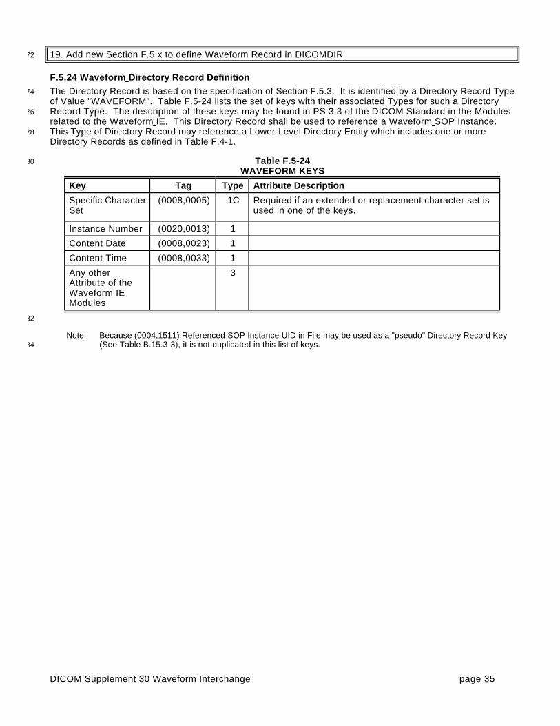
DICOM Supplement 30 Waveform Interchange page 35
19. Add new Section F.5.x to define Waveform Record in DICOMDIR72
F.5.24 Waveform Directory Record Definition
The Directory Record is based on the specification of Section F.5.3. It is identified by a Directory Record Type74of Value "WAVEFORM". Table F.5-24 lists the set of keys with their associated Types for such a DirectoryRecord Type. The description of these keys may be found in PS 3.3 of the DICOM Standard in the Modules76related to the Waveform IE. This Directory Record shall be used to reference a Waveform SOP Instance.This Type of Directory Record may reference a Lower-Level Directory Entity which includes one or more78Directory Records as defined in Table F.4-1.
Table F.5-2480WAVEFORM KEYS
Key Tag Type Attribute Description
Specific CharacterSet
(0008,0005) 1C Required if an extended or replacement character set isused in one of the keys.
Instance Number (0020,0013) 1
Content Date (0008,0023) 1
Content Time (0008,0033) 1
Any otherAttribute of theWaveform IEModules
3
82
Note: Because (0004,1511) Referenced SOP Instance UID in File may be used as a "pseudo" Directory Record Key(See Table B.15.3-3), it is not duplicated in this list of keys.84

DICOM Supplement 30 Waveform Interchange page 36
20. Add informative annex describing Waveforms86
Annex J - Waveforms (Informative)
J.1 DOMAIN OF APPLICATION88
Waveform acquisition is part of both the medical imaging environment and the general clinical environment.Because of its broad use, there has been significant previous and complementary work in waveform90standardization of which the following are particularly important:
ASTM E31.16 - E1467 Specification for Transferring Digital Neurophysiogical Data Between Independent92Computer Systems
CEN TC251 PT5-007 - prENV1064 draft Standard Communications Protocol for Computer-Assisted94Electrocardiography (SCP-ECG).
CEN TC251 PT5-021 - draft Vital Signs Information Representation Standard (VITAL)96
HL7 Automated Data SIG - HL7 Version 2.3, Chapter 7.14-20
IEEE P1073 - draft Medical Information Bus Standard (MIB)98
DICOM - NEMA PS3.3, Section A.10 Standalone Curve Information Object Definition
For DICOM, the domain of waveform standardization is waveform acquisition within the imaging context. It is00specifically meant to address waveform acquisitions which will be analyzed with other data which is transferredand managed using the DICOM protocol. It allows the addition of waveform data to that context with minimal02incremental cost. Further, it leverages the DICOM persistent object capability for maintaining referentialrelationships to other data collected in a multi-modality environment, including references necessary for multi-04modality synchronization.
Waveform interchange in other clinical contexts may use different protocols more appropriate to those06domains. In particular, HL7 may be used for transfer of waveform observations to general clinical informationsystems, and MIB may be used for real-time physiological monitoring and therapy.08
The waveform information object definition in DICOM has been specifically harmonized at the semantic levelwith the HL7 waveform message format. The use of a common object model allows straightforward10transcoding and interoperation between systems that use DICOM for waveform interchange and those thatuse HL7, and may be viewed as an example of common semantics implemented in the differing syntaxes of12two messaging systems.
Note: HL7 allows transport of DICOM SOP Instances (information objects) encapsulated within HL7 messages.14Since the DICOM and HL7 waveform semantics are harmonized, DICOM Waveform SOP Instances need notbe transported as encapsulated data, as they can be transcoded to native HL7 Waveform Observation format.16
J.2 USE CASES18
The following are specific use case examples for waveforms in the imaging environment.
Case 1: Catheterization Laboratory - During a cardiac catheterization, several independent pieces of data20
acquisition equipment may be brought together for the exam. An electrocardiographic subsystem recordssurface ECG waveforms; an X-ray angiographic subsystem records motion images; a hemodynamic22subsystem records intracardiac pressures from a sensor on the catheter. These subsystems send theiracquired data by network to a repository. These data are assembled at an analytic workstation by retrieving24from the repository. For a left ventriculographic procedure, the ECG is used by the physician to determine thetime of maximum and minimum ventricular fill, and when coordinated with the angiographic images, an26accurate estimate of the ejection fraction can be calculated. For a valvuloplasty procedure, thehemodynamic waveforms are used to calculate the pre-intervention and post-intervention pressure gradients.28

DICOM Supplement 30 Waveform Interchange page 37
Case 2: Electrophysiology Laboratory - An electrophysiological exam will capture waveforms from multiplesensors on a catheter; the placement of the catheter in the heart is captured on an angiographic image. At30an analytic workstation, the exact location of the sensors can thus be aligned with a model of the heart, andthe relative timing of the arrival of the electrophysiological waves at different cardiac locations can be32mapped.
Case 3: Stress Exam - A stress exam may involve the acquisition of both ECG waveforms and34
echocardiographic ultrasound images from portable equipment at different stages of the test. Thewaveforms and the echocardiograms are output on an interchange disk, which is then input and read at a36review station. The physician analyzes both types of data to make a diagnosis of cardiac health.
J.3 TIME SYNCHRONIZATION FRAME OF REFERENCE38
Synchronization of acquisition across multiple modalities in a single study (e.g., angiography andelectrocardiography) requires either a shared trigger, or a shared clock. A Synchronization Module within the40Frame of Reference Information Entity specifies the synchronization mechanism. A common temporalenvironment used by multiple equipment is identified by a shared Synchronization Frame of Reference UID.42How this UID is determined and distributed to the participating equipment is outside the scope of thestandard.44
The method used for time synchronization of equipment clocks is implementation or site specific, andtherefore outside the scope of this proposal. If required, standard time distribution protocols are available46(e.g., NTP, IRIG, GPS).
An informative description of time distribution methods can be found at:48http://www.bancomm.com/cntpApp.htm
A second method of synchronizing acquisitions is to utilize a common reference channel (temporal fiducial),50which is recorded in the data acquired from the several equipment units participating in a study, and/or whichis used to trigger synchronized data acquisitions. For instance, the “X-ray on” pulse train which triggers the52acquisition of frames for an X-ray angiographic SOP Instance can be recorded as a waveform channel in asimultaneously acquired hemodynamic waveform SOP Instance, and can be used to align the different54object instances. Associated with this Supplement are proposed coded entry channel identifiers to specificallysupport this synchronization mechanism (DICOM Terminology Mapping Resource Context Group ID 3090).56
J.4 WAVEFORM ACQUISITION MODEL
Figure J.4-1 shows a canonical model of waveform data acquisition. A patient is the subject of the study.58There may be several sensors placed at different locations on or in the patient, and waveforms aremeasurements of some physical quality (metric) by those sensors (e.g., electrical voltage, pressure, gas60concentration, or sound). The sensor is typically connected to an amplifier and filter, and its output issampled at constant time intervals and digitized. In most cases, several signal channels are acquired62synchronously. The measured signal usually originates in the anatomy of the patient, but an importantspecial case is a signal which originates in the equipment, either as a stimulus, such as a cardiac pacing64signal, as a therapy, such as a radio frequency signal used for ablation, or as a synchronization signal.

DICOM Supplement 30 Waveform Interchange page 38
Amplifier /Filter
Analog-to-Digital
Converter
WaveformDisplay
Processor
Sensors / transducers Electrical Pressure Gas concentration Sound RF electromagnetic
Stimulator
66
Figure J.4-1 - Waveform Acquisition Model
68
J.5 WAVEFORM INFORMATION MODEL
The part of the composite information object which carries the waveform data is the Waveform Information70Entity (IE). The Waveform IE includes the technical parameters of waveform acquisition and the waveformsamples.72
The information model, or internal organizational structure, of the Waveform IE is shown in Figure J.5-1. Awaveform information object includes data from a continuous time period during which signals were acquired.74The object may contain several multiplex groups, each defined by digitization with the same clock whosefrequency is defined for the group. Within each multiplex group there will be one or more channels, each with76a full technical definition. Finally, each channel has its set of digital waveform samples.

DICOM Supplement 30 Waveform Interchange page 39
Waveform
contains
MultiplexGroup
contains
Channel
contains
Sample
1
1,n
1,n
1
1,n
Channel DefinitionAttributes
Number of ChannelsSampling FrequencyTiming
1
Channel SourceMetricAnatomic Location(s)FunctionTechnique
Channel SensitivityBaselineSkewFilter Characteristics
WaveformAttributes
Time of AcquisitionAcquisition ContextAnnotation
Patient
issubject
of
Study
contains
Series
1
1,n
1
1,n
contains
1
Waveform
1,n
Multiplex GroupAttributes
78
Figure J.5-1 DICOM Waveform Information Model
80
J.6 HARMONIZATION WITH HL7
This Waveform IE definition is harmonized with the HL7 waveform semantic constructs, including the channel82definition attributes and the use of multiplex groups for synchronously acquired channels. The use of acommon object model allows straightforward transcoding and interoperation between systems that use84DICOM for waveform interchange and those that use HL7, and may be viewed as an example of commonsemantics implemented in the differing syntaxes of two messaging systems.86
This section describes the congruence between the DICOM Waveform IE and the HL7 version 2.3 waveformmessage format (see HL7 version 2.3 Chapter 7, sections 7.14 – 7.20).88
J.6.1 HL7 Waveform Observation
Waveforms in HL7 messages are sent in a set of OBX (Observation) Segments. Four subtypes of OBX90segments are defined:
- The CHN subtype defines one channel in a CD (Channel Definition) Data Type92
- The TIM subtype defines the start time of the waveform data in a TS (Time String) Data Type

DICOM Supplement 30 Waveform Interchange page 40
- The WAV subtype carries the waveform data in an NA (Numeric Array) or MA (Multiplexed Array) Data94Type (ASCII encoded samples, character delimited)
- The ANO subtype carries an annotation in a CE (Coded Entry) Data Type with a reference to a specific96time within the waveform to which the annotation applies
Other segments of the HL7 message definition specify patient and study identification, whose harmonization98with DICOM constructs is not defined in this Annex.
J.6.2 Channel Definition00
The Waveform Module Channel Definition sequence attribute (003A,0200) is defined in harmonization withthe HL7 Channel Definition (CD) Data Type, in accordance with the following Table. Each Item in the02Channel Definition sequence attribute corresponds to an OBX Segment of subtype CHN.
Table J.6-104Correspondence Between DICOM and HL7 Channel Definition
DICOM Attribute HL7 CD Data Type Component
Waveform Channel Number (003A,0202) Channel Identifier (number&name)
Channel Label (003A,0203)
Channel Source Sequence (003A,0208) Waveform Source
Channel Source Modifier Sequence (003A,0209)
Channel Sensitivity (003A,0210) Channel Sensitivity and Units
Channel Sensitivity Units Sequence (003A,0211)
Channel Sensitivity CorrectionFactor
(003A,0212) Channel Calibration Parameters
Channel Baseline (003A,0213) (correctionfactor&baseline×kew)
Channel Time Skew (003A,0214)
[Group] Sampling Frequency (003A,001A) Channel Sampling Frequency
Channel Minimum Value (5400,0110) Minimum and Maximum Data Values
Channel Maximum Value (5400,0112) (minimum&maximum)
Channel Offset (003A,0218) not defined in HL7
Channel Status (003A,0205)
Filter Low Frequency (003A,0220)
Filter High Frequency (003A,0221)
Notch Filter Frequency (003A,0222)
Notch Filter Bandwidth (003A,0223)06
In the DICOM information object definition, the sampling frequency is defined for the multiplex group, while inHL7 it is defined for each channel, but is required to be identical for all multiplexed channels.08
Note that in the HL7 syntax, Waveform Source is a string, rather than a coded entry as used in DICOM. Thisshould be considered in any transcoding between the two formats.10
J.6.3 Timing
In HL7, the exact start time for waveform data is sent in an OBX Segment of subtype TIM. The12corresponding DICOM attributes, which must be combined to form the equivalent time string, are:
Acquisition Datetime (0008,002A)
Multiplex Group Time Offset (0018,1068)14

DICOM Supplement 30 Waveform Interchange page 41
J.6.4 Waveform Data
The DICOM binary encoding of data samples in the Waveform Data attribute (5400,1010) corresponds to the16ASCII representation of data samples in the HL7 OBX Segment of subtype WAV. The same channel-interleaved multiplexing used in the HL7 MA (Multiplexed Array) Data Type is used in the DICOM Waveform18Data attribute.
Because of its binary representation, DICOM uses several data elements to specify the precise encoding, as20listed in the following Table. There are no corresponding HL7 data elements, since HL7 uses explicitcharacter-delimited ASCII encoding of data samples.22
Number of WaveformChannels
(003A,0005)
Number of WaveformSamples
(003A,0010)
Waveform Bits Stored (003A,021A)
Waveform Bits Allocated (5400,1004)
Waveform SampleInterpretation
(5400,1006)
Waveform Padding Value (5400,100A)
J.6.5 Annotation24
In HL7, Waveform Annotation is sent in an OBX Segment of subtype ANO, using the CE (Coded Entry) DataType CE. This corresponds precisely to the DICOM Annotation using Coded Entry Sequences. However,26HL7 annotation ROI is to a single point only (time reference), while DICOM allows reference to ranges ofsamples delimited by time or by explicit sample position.28
J.7 HARMONIZATION WITH SCP-ECG
The SCP-ECG standard is designed for recording routine resting electrocardiograms. Such ECGs are30reviewed prior to cardiac imaging procedures, and a typical use case would be for SCP-ECG waveforms to betranslated to DICOM for inclusion with the full cardiac imaging patient record.32
SCP-ECG provides for either simultaneous or non-simultaneous recording of the channels, but does notprovide a multiplexed data format (each channel is separately encoded). When translating to DICOM, each34subset of simultaneously recorded channels may be encoded in a Waveform Sequence Item (multiplexgroup), and the delay to the recording of each multiplex group shall be encoded in the Multiplex Group Time36Offset (0018,1068).
The electrode configuration of SCP-ECG Section 1 may be translated to the DICOM Acquisition Context38(0040,0555) sequence items using DICOM Terminology Mapping Resource Template 3401 and ContextGroups 3263 and 3264.40
The lead identification of SCP-ECG Section 3, a term coded as an unsigned integer, may be translated to theDICOM Waveform Channel Source (003A,0208) coded sequence using Context Group 3001.42
Pacemaker spike records of SCP-ECG Section 7 may be translated to items in the Waveform AnnotationSequence (0040,B020) with a code term from Context Group 3335. The annotation sequence item may44record the spike amplitude in its Numeric Value and Measurement Units attributes.
DICOM Supplement 30 Waveform Interchange page 42
46
48
50
52
Changes to:
NEMA Standards Publication PS 3.4-199954
Digital Imaging and Communications in Medicine (DICOM)
Part 4: Service Class Specifications56
58

DICOM Supplement 30 Waveform Interchange page 43
21.Modify Section B.5 to define Waveform SOP Classes for Network
B.5 STANDARD SOP CLASSES60
The SOP Classes in the Storage Service Class identify the Composite IODs to be stored. Table B.5-1identifies Standard SOP Classes.62
Table B.5-1 Standard SOP ClassesSOP Class Name SOP Class UID IOD Specification
…
12-lead ECG Waveform Storage 1.2.840.10008.5.1.4.1.1.9.1.1 12-lead ECG Waveform
General ECG Waveform Storage 1.2.840.10008.5.1.4.1.1.9.1.2 General ECG Waveform
Ambulatory ECG Waveform Storage 1.2.840.10008.5.1.4.1.1.9.1.3 Ambulatory ECG Waveform
Hemodynamic Waveform Storage 1.2.840.10008.5.1.4.1.1.9.2.1 Hemodynamic Waveform
Cardiac Electrophysiology WaveformStorage
1.2.840.10008.5.1.4.1.1.9.3.1 Cardiac ElectrophysiologyWaveform
Basic Voice Audio Waveform Storage 1.2.840.10008.5.1.4.1.1.9.4.1 Basic Voice Audio Waveform
64
22.Modify Section I.4 to define Waveform SOP Classes for Media66
I.4 MEDIA STORAGE STANDARD SOP CLASSES
The SOP Classes in the Media Storage Service Class identify the Composite and Normalized IODs to be68stored. Table I.4-1 identifies Standard SOP Classes.
Table I.4-1 Media Storage Standard SOP Classes70
SOP Class Name SOP Class UID IOD Specification
…
12-lead ECG Waveform Storage 1.2.840.10008.5.1.4.1.1.9.1.1 12-lead ECG Waveform
General ECG Waveform Storage 1.2.840.10008.5.1.4.1.1.9.1.2 General ECG Waveform
Ambulatory ECG Waveform Storage 1.2.840.10008.5.1.4.1.1.9.1.3 Ambulatory ECG Waveform
Hemodynamic Waveform Storage 1.2.840.10008.5.1.4.1.1.9.2.1 Hemodynamic Waveform
Cardiac Electrophysiology WaveformStorage
1.2.840.10008.5.1.4.1.1.9.3.1 Cardiac ElectrophysiologyWaveform
Basic Voice Audio Waveform Storage 1.2.840.10008.5.1.4.1.1.9.4.1 Basic Voice AudioWaveform

DICOM Supplement 30 Waveform Interchange page 44
72
74
76
78
Changes to:
NEMA Standards Publication PS 3.5-199980
Digital Imaging and Communications in Medicine (DICOM)
Part 5: Data Structures and Encoding82
84

DICOM Supplement 30 Waveform Interchange page 45
23. Modify Section 7.5 NESTING OF DATA SETS86
7.5 NESTING OF DATA SETS
The VR identified "SQ" shall be used for Data Elements with a Value consisting of a Sequence of zero or88more Items, where each Item contains a set of Data Elements. SQ provides a flexible encoding scheme thatmay be used for simple structures of repeating sets of Data Elements, or the encoding of more complex90Information Object Definitions often called folders. SQ Data Elements can also be used recursively to containmulti-level nested structures.92
Items present in an SQ Data Element shall be an ordered set where each Item may be referenced by itsordinal position. Each Item shall be implicitly assigned an ordinal position starting with the value 1 for the first94
Item in the Sequence, and incremented by 1 with each subsequent Item. The last Item in the Sequenceshall have an ordinal position equal to the number of Items in the Sequence.96
Notes:1- This clause implies that item ordering is preserved during transfer and storage.98
2- An IOD or Module Definition may choose to not use this ordering property of a Data E lement with VR of SQ.This is simply done by not specifying any specific semantics to the ordering of Items, or by not specifying00usage of the referencing of Items by ordering position.
02
…
04

DICOM Supplement 30 Waveform Interchange page 46
24. Modify PS 3.5 Section 8 to address Waveform use:
Section 8 Encoding of Pixel, and Overlay, and Waveform Data06
8.1 PIXEL AND OVERLA Y DATA, AND RELATED DATA ELEMENTS
The Pixel Data Element (7FE0,0010) and Overlay Data Element (60xx,3000) shall be used for the exchange08of encoded graphical image data. …
8.1 PIXEL AND OVERLAY DATA ENCODING OF RELATED DATA ELEMENTS10
8.1.1 Pixel data encoding of related data elements
Encoded Pixel Data of various bit depths shall be accommodated. The following three Data Elements shall12define the Pixel structure:
...14
8.3 WAVEFORM DATA AN D RELATED DATA ELEMENTS 16
The DICOM protocol provides for the exchange of encoded time-based signals, or waveforms, encoded inthe Waveform Data Element (5400,1010).18
Note: Per Section 7.6, an IOD supporting mu ltiple sets of Waveform Data will encapsulate Data Element (5400,1010)within a Sequence.20
Encoded Waveform Data of various bit depths is accommodated through the Waveform Bits Allocated(5400,1004) Data Element. This element defines the size of each waveform data sample within the22
Waveform Data (5400,1010). Allowed values are 8 and 16 bits.
The Value Representation of the Waveform Data (5400,1010) shall be OW; OB shall be used in cases24
where Waveform Bits Allocated has a value of 8, but only with Transfer Syntaxes where the ValueRepresentation is explicitly conveyed.26
Notes:1. Under the Default Transfer Syntax, OB and OW VRs have the identical byte transfer order.28
2. Conversion of a SOP Instance from the Default Transfer Syntax to an Explicit VR Transfer Syntax(uncompressed) requires the interpretation of the Waveform Bits Allocated (5400,1004) Data Element, to30determine the proper VR of the Waveform Data.
The following data elements related to Waveform Data shall be encoded with the same VR as Waveform32
Data: Channel Minimum Value (5400,0110), Channel Maximum Value (5400,0112), Waveform PaddingValue (5400,100A).34

DICOM Supplement 30 Waveform Interchange page 47
25.Modify PS 3.5 Annex A to address encoding of waveform data with OB/OW VR:36
A.1 DICOM IMPLICIT VR LITTLE ENDIAN TRANSFER SYNTAX38
...
c) The encoding of the Data Elements of the Data Set shall be as follows according to their Value40Representations: For all Value Representations defined in this part, except for the Value Representations OB and42
OW, the encoding shall be in Little Endian as specified in Section 7.3. For the Value Representations OB and OW, the encoding shall meet the following specification44
depending on the Data Element Tag: Data Element (7FE0,0010) Pixel Data has the Value Representation OW and shall be46
encoded in Little Endian. Data Element (60xx,3000) Overlay Data has the Value Representation OW and shall be48
encoded in Little Endian. Data Element (50xx,3000) Curve Data has the Value Representation OB with its component50
points (n-tuples) having the Value Representation specified in Data Value Representation(50xx,0103). The component points shall be encoded in Little Endian.52
Data Element (5400,1010) Waveform Data shall have Value Representation OWand shall be encoded in Little Endian.54
...
A.2 DICOM LITTLE ENDIAN TRANSFER SYNTAX (EXPLICIT VR)56
...
c) The encoding of the Data Elements of the Data Set shall be as follows according to their Value58Representations:
For all Value Representations defined in this part, except for the Value Representations OB and OW,60the encoding shall be in Little Endian as specified in Section 7.3.
For the Value Representations OB and OW, the encoding shall meet the following specification62depending on the Data Element Tag: Data Element (7FE0,0010) Pixel Data64
where Bits Allocated (0028,0100) has a value greater than 8 shall have Value RepresentationOW and shall be encoded in Little Endian;66
where Bits Allocated (0028,0100) has a value less than or equal to 8 shall have the ValueRepresentation OB or OW and shall be encoded in Little Endian.68
Data Element (60xx,3000) Overlay Data where Bits Allocated (60xx,0100) has a value greater than 8 shall have Value Representation70
OW and shall be encoded in Little Endian; where Bits Allocated (60xx,0100) has a value less than or equal to 8 shall have the Value72
Representation OB or OW and shall be encoded in Little Endian. Data Element (50xx,3000) Curve Data has the Value Representation specified in its Explicit VR74
Field. See the specification of the Curve Data Module in PS 3.3 for the enumerated list ofallowable VRs. The component points shall be encoded in Little Endian.76
Data Element (5400,1010) Waveform Data has the Value Representation specified in its Explic itVR Field. The component points shall be encoded in Little Endian.78
...
A.3 DICOM BIG ENDIAN TRANSFER SYNTAX (EXPLICIT VR)80
...

DICOM Supplement 30 Waveform Interchange page 48
c) The encoding of the Data Elements of the Data Set shall be as follows according to their Value82Representations:
For all Value Representations defined in this part, except for the Value Representations OB and OW,84the encoding shall be in Big Endian as specified in Section 7.3.
For the Value Representations OB and OW, the encoding shall meet the following specification86depending on the Data Element Tag: Data Element (7FE0,0010) Pixel Data88
where Bits Allocated (0028,0100) has a value greater than 8 shall have Value RepresentationOW and shall be encoded in Big Endian;90
where Bits Allocated (0028,0100) has a value less than or equal to 8 shall have the ValueRepresentation OB or OW and shall be encoded in Big Endian.92
Data Element (60xx,3000) Overlay Data where Bits Allocated (60xx,0100) has a value greater than 8 shall have Value Representation94
OW and shall be encoded in Big Endian; where Bits Allocated (60xx,0100) has a value less than or equal to 8 shall have the Value96
Representation OB or OW and shall be encoded in Big Endian. Data Element (50xx,3000) Curve Data has the Value Representation specified in its Explicit VR98
Field. See the specification of the Curve Data Module in PS 3.3 for the enumerated list ofallowable VRs. The component points shall be encoded in Big Endian.00
Data Element (5400,1010) Waveform Data has the Value Representation specified in its ExplicitVR Field. The component points shall be encoded in Big Endian.02
...
A.4 TRANSFER SYNTAXES FOR ENCAPSULATION OF ENCODED PIXEL DATA04
...
c) The encoding of the Data Elements of the Data Set shall be as follows according to their06Value Representations:
For all Value Representations defined in this part of the DICOM Standard, except for the Value08Representations OB and OW, the encoding shall be in Little Endian as specified in Section 7.3.
For the Value Representations OB and OW, the encoding shall meet the following specification10depending on the Data Element Tag:
...12
Data Element (50xx,3000) for Curve Data has the Value Representation specified in its Explicit VRField. See the specification of the Curve Data Module in PS 3.3 for the enumerated list of14allowable VRs. The component points shall be encoded in Little Endian.
Data Element (5400,1010) Waveform Data has the Value Representation specified in its16
Explicit VR Field. The component points shall be encoded in Little Endian.
...18

DICOM Supplement 30 Waveform Interchange page 49
20
22
24
26
Changes to:
NEMA Standards Publication PS 3.6-199928
Digital Imaging and Communications in Medicine (DICOM)
Part 6: Data Dictionary30
32

DICOM Supplement 30 Waveform Interchange page 50
26. Add new Attributes to Section 6
6 Registry of DICOM data elements34
Tag Attribute Name VR VM
(0008,002A) Acquisition Datetime DT 1
(0008,0023) Image Content Date DA 1
(0008,0033) Image Content Time TM 1
(0018,1067) Image Trigger Delay DS 1
(0018,1068) Multiplex Group Time Offset DS 1
(0018,1069) Trigger Time Offset DS 1
(0018,106A) Synchronization Trigger CS 1
(0018,106C) Synchronization Channel US 2
(0018,106E) Trigger Sample Position UL 1
(0018,1800) Acquisition Time Synchronized CS 1
(0018,1802) Time Distribution Protocol CS 1
(0018,1801) Time Source SH 1
(0020,0200) Synchronization Frame of Reference UID UI 1
(003A,0004) Waveform Originality CS 1
(003A,0005) Number of Waveform Channels US 1
(003A,0010) Number of Waveform Samples UL 1
(003A,001A) Sampling Frequency DS 1
(003A,0020) Multiplex Group Label SH 1
(003A,0200) Channel Definition Sequence SQ 1
(003A,0202) Waveform Channel Number IS 1
(003A,0203) Channel Label SH 1
(003A,0205) Channel Status CS 1-n
(003A,0208) Channel Source Sequence SQ 1
(003A,0209) Channel Source Modifiers Sequence SQ 1
(003A,020A) Source Waveform Sequence SQ 1
(003A,020C) Channel Derivation Description LO 1
(003A,0210) Channel Sensitivity DS 1
(003A,0211) Channel Sensitivity Units Sequence SQ 1
(003A,0212) Channel Sensitivity Correction Factor DS 1
(003A,0213) Channel Baseline DS 1
(003A,0214) Channel Time Skew DS 1

DICOM Supplement 30 Waveform Interchange page 51
Tag Attribute Name VR VM
(003A,0215) Channel Sample Skew DS 1
(003A,0218) Channel Offset DS 1
(003A,021A) Waveform Bits Stored US 1
(003A,0220) Filter Low Frequency DS 1
(003A,0221) Filter High Frequency DS 1
(003A,0222) Notch Filter Frequency DS 1
(003A,0223) Notch Filter Bandwidth DS 1
(0040,A0B0) Referenced Waveform Channels US 2-2n
(0040,A130) Temporal Range Type CS 1
(0040,A132) Referenced Sample Positions UL 1-n
(0040,A138) Referenced Time Offsets DS 1-n
(0040,A13A) Referenced Datetime DT 1-n
(0040,A180) Annotation Group Number US 1
(0040,A195) Modifier Code Sequence SQ 1
(0040,B020) Annotation Sequence SQ 1
(5400,0100) Waveform Sequence SQ 1
(5400,0110) Channel Minimum Value OB orOW
1
(5400,0112) Channel Maximum Value OB orOW
1
(5400,1004) Waveform Bits Allocated US 1
(5400,1006) Waveform Sample Interpretation CS 1
(5400,100A) Waveform Padding Value OB orOW
1
(5400,1010) Waveform Data OB orOW
1
36

DICOM Supplement 30 Waveform Interchange page 52
27. Add new SOP Classes to Table A-1
Annex A Registry of DICOM unique identifiers (UID)38
…
Table A-140UID VALUES
UID Value UID NAME UID TYPE Part
…
1.2.840.10008.5.1.4.1.1.9.1 .1
12-lead ECG Waveform Storage SOP Class PS 3.4
1.2.840.10008.5.1.4.1.1.9.1 .2
General ECG Waveform Storage SOP Class PS 3.4
1.2.840.10008.5.1.4.1.1.9.1 .3
Ambulatory ECG Waveform Storage SOP Class PS 3.4
1.2.840.10008.5.1.4.1.1.9.2 .1
Hemodynamic Waveform Storage SOP Class PS 3.4
1.2.840.10008.5.1.4.1.1.9.3 .1
Cardiac Electrophysiology WaveformStorage
SOP Class PS 3.4
1.2.840.10008.5.1.4.1.1.9.4 .1
Basic Voice Audio Waveform Storage SOP Class PS 3.4
42

DICOM Supplement 30 Waveform Interchange page 53
28. Add new Annexes to define Context Groups and Templates
Annex B – DICOM Terminology Mapping Resource44
Registry of Context Groups and Controlled Terminology
Table B-1 defines the Coding Schemes utilized in the controlled terminology specified in this Annex.46
Table B-1CODING SCHEME VALUES48
SNM3 SNOMED Version 3
SRT SNOMED RT
DCM DICOM
SCPECG Standard Communications Protocol for Computer-AssistedElectrocardiography, Draft proposal for ISO Standard, AAMI, Revision 1.3
BARI Bypass Angiography Revascularization Investigation, Alderman, EL andStadius, M, Coronary Artery Disease 1992,3:1189-1207; endorsed byACC/AHA Guidelines for Coronary Angiography, J Am Coll Cardiol1999,33:1791
UCUM The Unified Code for Units of Measure. Gunther Schadow Clement J.McDonald. The Regenstrief Institute For Health Care, Indianapolis
50
Context Group ID 3001Context Group Name ECG leads52
CodingScheme
CodingSchemeVersion
Code Value Code Meaning
SCPECG 1.3 5.6.3-9-73 Defibrillator lead: anterior-lateral
SCPECG 1.3 5.6.3-9-74 External pacing lead: anterior-posterior
SCPECG 1.3 5.6.3-9-27 Lead A
SCPECG 1.3 5.6.3-9-71 Lead A (Nehb – Anterior)
SCPECG 1.3 5.6.3-9-75 Lead A1 (Auxiliary unipolar lead 1)
SCPECG 1.3 5.6.3-9-76 Lead A2 (Auxiliary unipolar lead 2)
SCPECG 1.3 5.6.3-9-77 Lead A3 (Auxiliary unipolar lead 3)
SCPECG 1.3 5.6.3-9-78 Lead A4 (Auxiliary unipolar lead 4)
SCPECG 1.3 5.6.3-9-57 Lead A-cal
SCPECG 1.3 5.6.3-9-84 Lead A-cal (cal for Nehb – Anterior)
SCPECG 1.3 5.6.3-9-64 Lead aVF
SCPECG 1.3 5.6.3-9-63 Lead aVL
SCPECG 1.3 5.6.3-9-62 Lead aVR
SCPECG 1.3 5.6.3-9-65 Lead -aVR
SCPECG 1.3 5.6.3-9-26 Lead C
SCPECG 1.3 5.6.3-9-19 Lead CC5

DICOM Supplement 30 Waveform Interchange page 54
SCPECG 1.3 5.6.3-9-49 Lead CC5-cal
SCPECG 1.3 5.6.3-9-56 Lead C-cal
SCPECG 1.3 5.6.3-9-20 Lead CM5
SCPECG 1.3 5.6.3-9-50 Lead CM5-cal
SCPECG 1.3 5.6.3-9-70 Lead D (Nehb – Dorsal)
SCPECG 1.3 5.6.3-9-83 Lead D-cal (cal for Nehb – Dorsal)
SCPECG 1.3 5.6.3-9-25 Lead E
SCPECG 1.3 5.6.3-9-55 Lead E-cal
SCPECG 1.3 5.6.3-9-29 Lead F
SCPECG 1.3 5.6.3-9-59 Lead F-cal
SCPECG 1.3 5.6.3-9-30 Lead H
SCPECG 1.3 5.6.3-9-60 Lead H-cal
SCPECG 1.3 5.6.3-9-1 Lead I (Einthoven)
SCPECG 1.3 5.6.3-9-24 Lead I (Frank)
SCPECG 1.3 5.6.3-9-31 Lead I-cal (Einthoven)
SCPECG 1.3 5.6.3-9-54 Lead I-cal (Frank)
SCPECG 1.3 5.6.3-9-2 Lead II
SCPECG 1.3 5.6.3-9-32 Lead II-cal
SCPECG 1.3 5.6.3-9-61 Lead III
SCPECG 1.3 5.6.3-9-72 Lead J (Nehb – Inferior)
SCPECG 1.3 5.6.3-9-85 Lead J-cal (cal for Nehb – Inferior)
SCPECG 1.3 5.6.3-9-21 Lead Left Arm
SCPECG 1.3 5.6.3-9-51 Lead Left Arm-cal
SCPECG 1.3 5.6.3-9-23 Lead Left Leg
SCPECG 1.3 5.6.3-9-53 Lead Left Leg-cal
SCPECG 1.3 5.6.3-9-28 Lead M
SCPECG 1.3 5.6.3-9-58 Lead M-cal
SCPECG 1.3 5.6.3-9-22 Lead Right Arm
SCPECG 1.3 5.6.3-9-52 Lead Right Arm-cal
SCPECG 1.3 5.6.3-9-3 Lead V1
SCPECG 1.3 5.6.3-9-33 Lead V1-cal
SCPECG 1.3 5.6.3-9-4 Lead V2
SCPECG 1.3 5.6.3-9-34 Lead V2-cal
SCPECG 1.3 5.6.3-9-10 Lead V2R
SCPECG 1.3 5.6.3-9-40 Lead V2R-cal
SCPECG 1.3 5.6.3-9-5 Lead V3
SCPECG 1.3 5.6.3-9-35 Lead V3-cal
SCPECG 1.3 5.6.3-9-11 Lead V3R
SCPECG 1.3 5.6.3-9-41 Lead V3R-cal
SCPECG 1.3 5.6.3-9-6 Lead V4
SCPECG 1.3 5.6.3-9-36 Lead V4-cal
SCPECG 1.3 5.6.3-9-12 Lead V4R

DICOM Supplement 30 Waveform Interchange page 55
SCPECG 1.3 5.6.3-9-42 Lead V4R-cal
SCPECG 1.3 5.6.3-9-7 Lead V5
SCPECG 1.3 5.6.3-9-37 Lead V5-cal
SCPECG 1.3 5.6.3-9-13 Lead V5R
SCPECG 1.3 5.6.3-9-43 Lead V5R-cal
SCPECG 1.3 5.6.3-9-8 Lead V6
SCPECG 1.3 5.6.3-9-38 Lead V6-cal
SCPECG 1.3 5.6.3-9-14 Lead V6R
SCPECG 1.3 5.6.3-9-44 Lead V6R-cal
SCPECG 1.3 5.6.3-9-9 Lead V7
SCPECG 1.3 5.6.3-9-39 Lead V7-cal
SCPECG 1.3 5.6.3-9-15 Lead V7R
SCPECG 1.3 5.6.3-9-45 Lead V7R-cal
SCPECG 1.3 5.6.3-9-66 Lead V8
SCPECG 1.3 5.6.3-9-79 Lead V8-cal
SCPECG 1.3 5.6.3-9-68 Lead V8R
SCPECG 1.3 5.6.3-9-81 Lead V8R-cal
SCPECG 1.3 5.6.3-9-67 Lead V9
SCPECG 1.3 5.6.3-9-80 Lead V9-cal
SCPECG 1.3 5.6.3-9-69 Lead V9R
SCPECG 1.3 5.6.3-9-82 Lead V9R-cal
SCPECG 1.3 5.6.3-9-16 Lead X
SCPECG 1.3 5.6.3-9-46 Lead X-cal
SCPECG 1.3 5.6.3-9-17 Lead Y
SCPECG 1.3 5.6.3-9-47 Lead Y-cal
SCPECG 1.3 5.6.3-9-18 Lead Z
SCPECG 1.3 5.6.3-9-48 Lead Z-cal
SCPECG 1.3 5.6.3-9-0 Unspecified lead
Context Group ID 300354Context Group Name Hemodynamic waveform sources
CodingScheme
CodingSchemeVersion
Code Value Code Meaning
SRT V1 G-DB22 Aortic pressure waveform
SRT V1 G-DB31 Aortic valve pullback pressure waveform
SRT V1 G-DB24 Arterial pressure waveform
SRT V1 G-DB23 Central venous pressure waveform
SRT V1 G-DB33 Dye dilution cardiac output waveform
SRT V1 G-DB20 Femoral artery pressure waveform
SRT V1 G-DB34 Hemodynamic impedance waveform
SRT V1 G-DB19 Left atrium pressure waveform
SRT V1 G-DB16 Left ventricle pressure waveform

DICOM Supplement 30 Waveform Interchange page 56
SRT V1 G-DB28 Mitral valve pullback pressure waveform
SRT V1 G-DB25 Pulmonary artery oxygen saturation waveform
SRT V1 G-DB21 Pulmonary artery pressure waveform
SRT V1 G-DB27 Pulmonary artery wedge pressure waveform
SRT V1 G-DB26 Pulmonary capillary wedge pressure waveform
SRT V1 G-DB30 Pulmonary valve pullback pressure waveform
SRT V1 G-DB18 Right atrium pressure waveform
SRT V1 G-DB17 Right ventricle pressure waveform
SRT V1 G-DB32 Thermal cardiac output waveform
SRT V1 G-DB29 Tricuspid valve pullback pressure waveform56
Context Group ID 3010Context Group Name Cardiovascular anatomic locations58
CodingScheme
CodingSchemeVersion
Code Value Code Meaning
SNM3 3.4 T-42500 Abdominal aorta
SRT V1 T-48503 Anomalous pulmonary vein
SRT V1 T-49215 Antecubital vein
SNM3 3.5 T-45530 Anterior communicating artery
SNM3 3.5 T-45730 Anterior spinal artery
SNM3 3.5 T-47700 Anterior tibial artery
SNM3 3.4 T-42000 Aorta
SNM3 3.5 T-42300 Aortic arch
SRT V1 D3-81922 Aortic fistula
SRT V1 T-32602 Apex of left ventricle
SRT V1 T-32502 Apex of right ventricle
SNM3 3.5 T-41000 Artery
SNM3 3.5 T-42100 Ascending aorta
SNM3 3.4 T-47100 Axillary Artery
SNM3 3.5 T-49110 Axillary vein
SNM3 3.4 T-48340 Azygos vein
SRT V1 A-00203 Baffle
SNM3 3.5 T-45800 Basilar artery
SNM3 3.5 T-D00AB Body conduit
SRT V1 T-49424 Boyd’s perforating vein
SNM3 3.5 T-47160 Brachial artery
SNM3 3.4 T-49350 Brachial vein
SNM3 3.5 T-46010 Brachiocephalic artery
SNM3 3.5 T-46010 Brachiocephalic trunk
SNM3 3.5 T-48620 Brachiocephalic vein
SNM3 3.4 T-45010 Carotid Artery
SNM3 3.5 T-49240 Cephalic vein
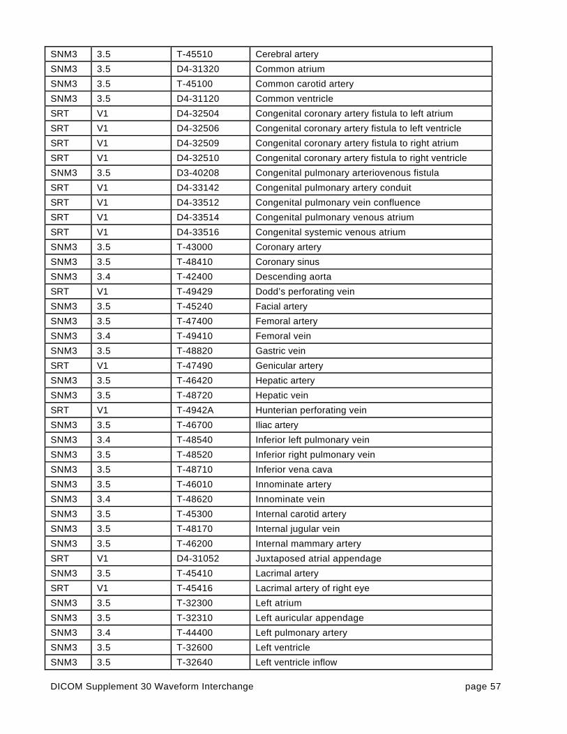
DICOM Supplement 30 Waveform Interchange page 57
SNM3 3.5 T-45510 Cerebral artery
SNM3 3.5 D4-31320 Common atrium
SNM3 3.5 T-45100 Common carotid artery
SNM3 3.5 D4-31120 Common ventricle
SRT V1 D4-32504 Congenital coronary artery fistula to left atrium
SRT V1 D4-32506 Congenital coronary artery fistula to left ventricle
SRT V1 D4-32509 Congenital coronary artery fistula to right atrium
SRT V1 D4-32510 Congenital coronary artery fistula to right ventricle
SNM3 3.5 D3-40208 Congenital pulmonary arteriovenous fistula
SRT V1 D4-33142 Congenital pulmonary artery conduit
SRT V1 D4-33512 Congenital pulmonary vein confluence
SRT V1 D4-33514 Congenital pulmonary venous atrium
SRT V1 D4-33516 Congenital systemic venous atrium
SNM3 3.5 T-43000 Coronary artery
SNM3 3.5 T-48410 Coronary sinus
SNM3 3.4 T-42400 Descending aorta
SRT V1 T-49429 Dodd’s perforating vein
SNM3 3.5 T-45240 Facial artery
SNM3 3.5 T-47400 Femoral artery
SNM3 3.4 T-49410 Femoral vein
SNM3 3.5 T-48820 Gastric vein
SRT V1 T-47490 Genicular artery
SNM3 3.5 T-46420 Hepatic artery
SNM3 3.5 T-48720 Hepatic vein
SRT V1 T-4942A Hunterian perforating vein
SNM3 3.5 T-46700 Iliac artery
SNM3 3.4 T-48540 Inferior left pulmonary vein
SNM3 3.5 T-48520 Inferior right pulmonary vein
SNM3 3.5 T-48710 Inferior vena cava
SNM3 3.5 T-46010 Innominate artery
SNM3 3.4 T-48620 Innominate vein
SNM3 3.5 T-45300 Internal carotid artery
SNM3 3.5 T-48170 Internal jugular vein
SNM3 3.5 T-46200 Internal mammary artery
SRT V1 D4-31052 Juxtaposed atrial appendage
SNM3 3.5 T-45410 Lacrimal artery
SRT V1 T-45416 Lacrimal artery of right eye
SNM3 3.5 T-32300 Left atrium
SNM3 3.5 T-32310 Left auricular appendage
SNM3 3.4 T-44400 Left pulmonary artery
SNM3 3.5 T-32600 Left ventricle
SNM3 3.5 T-32640 Left ventricle inflow

DICOM Supplement 30 Waveform Interchange page 58
SRT V1 D4-31022 Left ventricle outflow chamber
SNM3 3.5 T-32640 Left ventricle outflow tract
SNM3 3.5 T-45230 Lingual artery
SNM3 3.5 T-46960 Lumbar artery
SNM3 3.5 T-46500 Mesenteric artery
SRT V1 T-4884A Mesenteric vein
SNM3 3.5 T-45250 Occipital artery
SNM3 3.5 T-48214 Occipital vein
SNM3 3.5 T-45400 Ophthalmic artery
SNM3 3.5 D4-32012 Patent ductus arteriosus
SNM3 3.5 T-47630 Peroneal artery
SNM3 3.5 T-47500 Popliteal artery
SNM3 3.5 T-48810 Portal vein
SNM3 3.5 T-45320 Posterior communication artery
SRT V1 T-49535 Posterior medial tributary
SNM3 3.5 T-47600 Posterior tibial artery
SNM3 3.5 T-F7001 Primitive aorta
SNM3 3.5 T-F7040 Primitive pulmonary artery
SNM3 3.5 T-44000 Pulmonary artery
SRT V1 T-32190 Pulmonary chamber of cor triatriatum
SNM3 3.5 T-48500 Pulmonary vein
SNM3 3.5 T-47300 Radial artery
SNM3 3.5 T-46600 Renal artery
SNM3 3.5 T-48740 Renal vein
SNM3 3.5 T-32200 Right atrium
SNM3 3.5 T-32210 Right auricular appendage
SNM3 3.5 T-47410 Right femoral artery
SNM3 3.5 T-44200 Right pulmonary artery
SNM3 3.5 T-32500 Right ventricle
SNM3 3.5 T-32540 Right ventricle inflow
SRT V1 D4-31022 Right ventricle outflow chamber
SNM3 3.5 T-32550 Right ventricle outflow tract
SRT V1 T-D930A Saphenofemoral junction
SNM3 3.5 T-49530 Saphenous vein
SNM3 3.5 T-48890 Splenic vein
SNM3 3.5 T-46100 Subclavian artery
SNM3 3.5 T-48330 Subclavian vein
SNM3 3.5 T-45270 Superficial temporal artery
SNM3 3.5 T-48530 Superior left pulmonary vein
SNM3 3.5 T-48510 Superior right pulmonary vein
SNM3 3.5 T-45210 Superior thyroid artery
SNM3 3.5 T-48610 Superior vena cava

DICOM Supplement 30 Waveform Interchange page 59
SRT V1 T-44007 Systemic collateral artery to lung
SNM3 3.5 T-42070 Thoracic aorta
SNM3 3.5 D4-31400 Truncus arteriosus communis
SNM3 3.5 T-F1810 Umbilical artery
SNM3 3.5 T-48817 Umbilical vein
SNM3 3.5 T-48000 Vein
SNM3 3.4 T-48170 Vena jugularis interna
SNM3 3.5 T-48003 Venous network
SNM3 3.5 T-45700 Vertebral artery
Context Group ID 301160Context Group Name Electrophysiology anatomic locations
CodingScheme
CodingSchemeVersion
Code Value Code Meaning
SNM3 3.5 T-32850 Accessory atrioventricular bundle
SRT V1 T-32602 Apex of left ventricle
SRT V1 T-32502 Apex of right ventricle
SNM3 3.5 T-32830 Atrioventricular bundle
SNM3 3.5 T-32820 Atrioventricular node
SNM3 3.5 T-32400 Common ventricle
SNM3 3.5 T-48410 Coronary sinus
SNM3 3.5 T-39010 Epicardium
SNM3 3.5 T-48420 Great cardiac vein
SRT V1 G-DE02 High right atrium
SNM3 3.5 T-48540 Inferior left pulmonary vein
SNM3 3.5 T-48520 Inferior right pulmonary vein
SRT V1 G-DE04 Lateral high right atrium
SNM3 3.5 T-32833 Left anterior division of left branch of leftatrioventricular bundle
SNM3 3.5 T-32300 Left Atrium
SNM3 3.5 T-32310 Left auricular appendage
SNM3 3.5 T-32832 Left branch of atrioventricular bundle
SNM3 3.5 T-32834 Left posterior division of left branch of leftatrioventricular bundle
SNM3 3.5 T-32600 Left ventricle
SNM3 3.5 T-32640 Left ventricle inflow
SNM3 3.5 T-32640 Left ventricle outflow tract
SRT V1 G-DE08 Low right atrium
SRT V1 G-DE06 Mid right atrium
SNM3 3.5 T-48430 Middle cardiac vein
SNM3 3.5 T-35310 Mitral ring
SNM3 3.5 T-48411 Ostium of coronary sinus

DICOM Supplement 30 Waveform Interchange page 60
SNM3 3.5 T-48500 Pulmonary vein
SNM3 3.5 T-35210 Pulmonic ring
SNM3 3.5 T-32840 Purkinje fibers
SNM3 3.5 T-35120 Right atrioventricular ostium
SNM3 3.5 T-32200 Right Atrium
SNM3 3.5 T-32210 Right auricular appendage
SNM3 3.5 T-32831 Right branch of Atrioventricular bundle
SNM3 3.5 T-32500 Right ventricle
SNM3 3.5 T-32540 Right ventricle inflow
SNM3 3.5 T-32550 Right ventricle outflow tract
SNM3 3.5 T-32810 Sino-atrial node
SNM3 3.5 T-48530 Superior left pulmonary vein
SNM3 3.5 T-48510 Superior right pulmonary vein
SRT V1 T-32202 Tendon of Todaro
SNM3 3.5 T-35110 Tricuspid ring62
Context Group ID 3014Context Group Name Coronary artery segments64
CodingScheme
CodingSchemeVersion
Code Value Code Meaning
BARI 1992 15 1st Diagonal Coronary Artery
BARI 1992 24 1st Left Posterolateral Coronary Artery
BARI 1992 20 1st Marginal Coronary Artery
BARI 1992 6 1st Right posterolateral
BARI 1992 17 1st Septal Coronary Artery
BARI 1992 16 2nd Diagonal Coronary Artery
BARI 1992 25 2nd Left Posterolateral Coronary Artery
BARI 1992 21 2nd Marginal Coronary Artery
BARI 1992 7 2nd Right posterolateral
BARI 1992 29 3rd diagonal
BARI 1992 26 3rd Left Posterolateral Coronary Artery
BARI 1992 22 3rd Marginal Coronary Artery
BARI 1992 8 3rd Right posterolateral
BARI 1992 10 Acute Marginal
BARI 1992 23 AV groove continuation
BARI 1992 19A Distal Circumflex Coronary Artery
BARI 1992 14 Distal Left Anterior Descending Coronary Artery
BARI 1992 3 Distal Right Coronary Artery
BARI 1992 15A Lateral 1st Diagonal Coronary Artery
BARI 1992 20A Lateral 1st Marginal Coronary Artery
BARI 1992 16A Lateral 2nd Diagonal Coronary Artery
BARI 1992 21A Lateral 2nd Marginal Coronary Artery
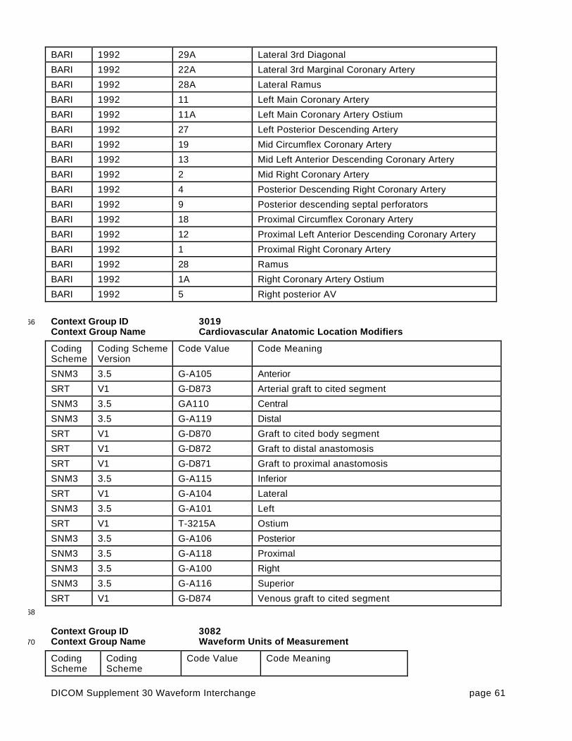
DICOM Supplement 30 Waveform Interchange page 61
BARI 1992 29A Lateral 3rd Diagonal
BARI 1992 22A Lateral 3rd Marginal Coronary Artery
BARI 1992 28A Lateral Ramus
BARI 1992 11 Left Main Coronary Artery
BARI 1992 11A Left Main Coronary Artery Ostium
BARI 1992 27 Left Posterior Descending Artery
BARI 1992 19 Mid Circumflex Coronary Artery
BARI 1992 13 Mid Left Anterior Descending Coronary Artery
BARI 1992 2 Mid Right Coronary Artery
BARI 1992 4 Posterior Descending Right Coronary Artery
BARI 1992 9 Posterior descending septal perforators
BARI 1992 18 Proximal Circumflex Coronary Artery
BARI 1992 12 Proximal Left Anterior Descending Coronary Artery
BARI 1992 1 Proximal Right Coronary Artery
BARI 1992 28 Ramus
BARI 1992 1A Right Coronary Artery Ostium
BARI 1992 5 Right posterior AV
Context Group ID 301966Context Group Name Cardiovascular Anatomic Location Modifiers
CodingScheme
Coding SchemeVersion
Code Value Code Meaning
SNM3 3.5 G-A105 Anterior
SRT V1 G-D873 Arterial graft to cited segment
SNM3 3.5 GA110 Central
SNM3 3.5 G-A119 Distal
SRT V1 G-D870 Graft to cited body segment
SRT V1 G-D872 Graft to distal anastomosis
SRT V1 G-D871 Graft to proximal anastomosis
SNM3 3.5 G-A115 Inferior
SRT V1 G-A104 Lateral
SNM3 3.5 G-A101 Left
SRT V1 T-3215A Ostium
SNM3 3.5 G-A106 Posterior
SNM3 3.5 G-A118 Proximal
SNM3 3.5 G-A100 Right
SNM3 3.5 G-A116 Superior
SRT V1 G-D874 Venous graft to cited segment68
Context Group ID 3082Context Group Name Waveform Units of Measurement70
CodingScheme
CodingScheme
Code Value Code Meaning

DICOM Supplement 30 Waveform Interchange page 62
Version
UCUM 1.4 dB(A) A scale of loudness
UCUM 1.4 [arb’U] arbitrary unit
UCUM 1.4 d day
UCUM 1.4 dB decibel
UCUM 1.4 Cel degrees Celsius
UCUM 1.4 {H.B.}/min Heart beat per minute
UCUM 1.4 hr hour
UCUM 1.4 J Joule
UCUM 1.4 kOhm kilo Ohm
UCUM 1.4 km/hr kilometer per hour
UCUM 1.4 kPa kiloPascal
UCUM 1.4 l/min liter per minute
UCUM 1.5 [MET] Metabolic equivalent
UCUM 1.4 uV microvolt
UCUM 1.4 [mi_i]/hr mile per hour
UCUM 1.4 ml/min milliliter per minute
UCUM 1.4 ml/s milliliter per second
UCUM 1.4 mm[Hg] millimeter of mercury
UCUM 1.4 mV millivolt
UCUM 1.4 min minute
UCUM 1.4 mm/s mm/s
UCUM 1.4 % percent
UCUM 1.4 s second
UCUM 1.4 1 unary, no units
UCUM 1.4 V volt
UCUM 1.4 W Watt
Context Group ID 309072Context Group Name Time Synchronization channel types
CodingScheme
Coding SchemeVersion
Code Value Code Meaning
DCM 01 109001 Digital timecode (NOS)
DCM 01 109002 ECG-based gating signal, processed
DCM 01 109003 IRIG-B timecode
DCM 01 109004 X-ray Fluoroscopy On Signal
DCM 01 109005 X-ray On Trigger74
Context Group ID 3240Context Group Name Electrophysiology measurement functions and techniques76
CodingScheme
CodingSchemeVersion
Code Value Code Meaning

DICOM Supplement 30 Waveform Interchange page 63
DCM 01 109006 Differential signal
DCM 01 109007 His bundle electrogram
DCM 01 109008 Monopole signal
DCM 01 109009 Pacing (electrical) stimulus, voltage
DCM 01 109010 Radio frequency ablation, power
DCM 01 109011 Voltage measurement by basket catheter
DCM 01 109012 Voltage measurement by mapping catheter
DCM 01 109013 Voltage measurement, NOS
Context Group ID 324178Context Group Name Hemodynamic measurement techniques
CodingScheme
Coding SchemeVersion
Code Value Code Meaning
SRT V1 PA-50038 Averaged hemodynamic measurement method
SRT V1 PA-50035 Composite hemodynamic measurement method
SRT V1 PA-50034 Computed hemodynamic measurement method
SRT V1 PA-50031 Dual catheter method
SRT V1 PA-50039 Fluid filled catheter method
SRT V1 PA-50033 Pullback method
SRT V1 PA-50032 Pulmonary capillary wedge method
SRT V1 PA-50036 Static catheter method
SRT V1 PA-5003A Tip manometer method
SRT V1 PA-50037 Wedge method80
Context Group ID 3250Context Group Name Catheterization Procedure Phase82
CodingScheme
CodingSchemeVersion
Code Value Code Meaning
SRT V1 G-7299 Cardiac catheterization bailout phase
SRT V1 G-7293 Cardiac catheterization baseline phase
SRT V1 G-7294 Cardiac catheterization image acquisition phase
SRT V1 G-7295 Cardiac catheterization intervention phase
SRT V1 G-729B Cardiac catheterization post contrast phase
SRT V1 G-7298 Cardiac catheterization post-intervention phase
SRT V1 G-7296 Cardiac catheterization pre-intervention phase
SRT V1 G-7297 Cardiac catheterization therapy phase
SRT V1 P1-3160A Catheterization of both left and right heart with graft
SRT V1 P1-3160B Catheterization of both left and right heart without graft
SNM3 3.5 P1-31604 Catheterization of left heart
SNM3 3.5 P1-31602 Catheterization of right heart

DICOM Supplement 30 Waveform Interchange page 64
Context Group ID 325484Context Group Name Electrophysiology Procedure Phase
CodingScheme
CodingSchemeVersion
Code Value Code Meaning
SRT V1 G-729D Atrial Effective Refractory Period, evaluation of
SRT V1 G-7304 Carotid Sinus Massage procedure phase
SRT V1 G-7306 Electrophysiology Mapping phase
SRT V1 G-729A Electrophysiology procedure baseline phase
SRT V1 G-7408 Post-ablation phase
SRT V1 G-7305 Post-defibrillation procedure phase
SRT V1 G-729F Radiofrequency Ablation procedure phase
SRT V1 G-729C Sinus Node Recovery Time, evaluation of
SRT V1 G-729E Ventricular Effective Refractory Period, evaluation of86
Context Group ID 3261Context Group Name Stress Protocols88
CodingScheme
CodingSchemeVersion
Code Value Code Meaning
SRT V1 P2-7131C Balke protocol
SRT V1 P2-7131A Bruce protocol
SRT V1 P2-7131D Ellestad protocol
SRT V1 P2-7131B Modified Bruce protocol
SRT V1 P2-713A1 Modified Naughton protocol
SRT V1 P2-713A0 Naughton protocol
SRT V1 P2-7131F Pepper protocol
SRT V1 P2-7131E Ramp protocol
Context Group ID 326290Context Group Name ECG Patient State Values
CodingScheme
CodingSchemeVersion
Code Value Code Meaning
SRT V1 F-01602 Baseline state
SRT V1 F-01606 Exercise state
SRT V1 F-01608 Post-exercise state
SRT V1 F-01604 Resting state
SNM3 3.5 F-10340 Supine body position92

DICOM Supplement 30 Waveform Interchange page 65
Context Group ID 3263Context Group Name Electrode Placement Values94
CodingScheme
CodingSchemeVersion
Code Value Code Meaning
SCPECG 1.3 5.4.5-33-1-5 12-lead ECG derived from Frank XYZ leads
SCPECG 1.3 5.4.5-33-1-6 12-lead ECG derived from non-standard leads
SCPECG 1.3 5.4.5-33-1-2 Mason-Likar positions: RA, RL, LA, and LL placed onthe torso. V1 to V6 placed at standard positions on thechest. All electrodes are placed individually.
SCPECG 1.3 5.4.5-33-1-3 Mason-Likar with V pad: RA, RL, LA, and LL individuallyplaced on the torso. V1 to V6 placed on the chest aspart of a single electrode pad (not placed individually).
SCPECG 1.3 5.4.5-33-1-4 Single electrode pad: All electrodes placed on the chestin a single electrode pad. None of the electrodes areplaced individually
SCPECG 1.3 5.4.5-33-1-1 Standard 12-lead positions: RA, RL, LA, and LL placedat limb extremities; V1 to V6 placed at standardpositions on the chest. All electrodes are placedindividually.
SCPECG 1.3 5.4.5-33-1-0 Unspecified
Context Group ID 326496Context Group Name XYZ Electrode Placement Values
CodingScheme
CodingSchemeVersion
Code Value Code Meaning
SCPECG 1.3 5.4.5-33-2-4 Bipolar uncorrected XYZ lead system
SCPECG 1.3 5.4.5-33-2-3 Cube lead system (Grishman et al, Amer Heart J 1951;41:483).
SCPECG 1.3 5.4.5-33-2-1 Frank lead system (Frank, 1956; 13:737)
SCPECG 1.3 5.4.5-33-2-2 McFee-Parungao lead system (Benchimol,Vectorcardiography, Williams & Wilkins, Baltimore,1973, Fig 1.6 on page 6)
SCPECG 1.3 5.4.5-33-2-5 Pseudo-orthogonal XYZ lead system (as used in Holterrecording)
SCPECG 1.3 5.4.5-33-2-0 Unspecified
SCPECG 1.3 5.4.5-33-2-6 XYZ leads derived from standard 12-lead ECG98
Context Group ID 3271Context Group Name Hemodynamic Physiological Challenges00
CodingScheme
CodingSchemeVersion
Code Value Code Meaning
SRT V1 P2-71310 Exercise challenge
SRT V1 P2-71306 Handgrip
SRT V1 P2-71302 Head up
SRT V1 P2-71314 Held inspiration

DICOM Supplement 30 Waveform Interchange page 66
SRT V1 P2-71316 Held ventilation
SRT V1 P2-71304 Leg up
SRT V1 P2-71308 Negative lower body pressure
SRT V1 P2-71318 Post volume challenge
SRT V1 P2-71312 Vagal stimulation
SNM3 3.5 F-F7102 Valsalva maneuver
Context Group ID 333502Context Group Name ECG Annotations
CodingScheme
CodingSchemeVersion
Code Value Code Meaning
SCPECG 1.3 5.7.1-3 Fiducial point
SCPECG 1.3 D.4.1-J J point
SCPECG 1.3 D.4.1-ST20 J point + 20 msec
SCPECG 1.3 D.4.1-ST60 J point + 60 msec
SCPECG 1.3 D.4.1-ST80 J point +80 msec
SCPECG 1.3 5.10.3-2 P wave end
SCPECG 1.3 5.10.3-1 P wave onset
SCPECG 1.3 D.4.1-P P wave peak
SCPECG 1.3 5.10.1.2 Pacemaker spike, suppressed
SCPECG 1.3 D.4.1-PR PR segment (isoelectric point)
SCPECG 1.3 D.4.1-Q Q wave
SCPECG 1.3 5.10.3-4 QRS end
SCPECG 1.3 5.10.3-3 QRS onset
SCPECG 1.3 D.4.1-R R wave peak
SCPECG 1.3 D.4.1-R2 R’ peak
SCPECG 1.3 D.4.1-S S wave
SCPECG 1.3 D.4.1-S2 S’ wave
SCPECG 1.3 5.10.3-5 T wave end
SCPECG 1.3 D.4.1-STE T wave onset
SCPECG 1.3 D.4.1-T T wave peak
SCPECG 1.3 D.4.1-U U wave peak04
Context Group ID 3337Context Group Name Hemodynamic Annotations06
CodingScheme
CodingSchemeVersion
Code Value Code Meaning
DCM 01 109014 35% of thermal CO
DCM 01 109015 70% of thermal CO
DCM 01 109016 A wave
DCM 01 109017 A wave average

DICOM Supplement 30 Waveform Interchange page 67
DCM 01 109018 Beat detected (accepted)
DCM 01 109019 Beat detected (rejected)
DCM 01 109020 Diastolic average
DCM 01 109021 Diastolic nadir
DCM 01 109022 End diastole
DCM 01 109023 End of expiration
DCM 01 109024 End of inspiration
DCM 01 109025 Max dp/dt
DCM 01 109026 Max neg dp/dt
DCM 01 109027 Mean pressure
DCM 01 109028 Peak of thermal CO
DCM 01 109029 Start of expiration
DCM 01 109030 Start of inspiration
DCM 01 109031 Start of thermal CO
DCM 01 109032 Systolic average
DCM 01 109033 Systolic peak
DCM 01 109034 V wave
DCM 01 109035 V wave average
DCM 01 109036 Valve close
DCM 01 109037 Valve open
Context Group ID 333908Context Group Name Electrophysiology Annotations
CodingScheme
CodingSchemeVersion
Code Value Code Meaning
DCM 01 109038 Ablation off
DCM 01 109039 Ablation on
DCM 01 109040 HIS bundle wave
DCM 01 109041 P wave
DCM 01 109042 Q wave
DCM 01 109043 R wave
DCM 01 109044 S wave
DCM 01 109045 Start of atrial contraction
DCM 01 109046 Start of atrial contraction (subsequent)
DCM 01 109047 Stimulation at rate 1 interval
DCM 01 109048 Stimulation at rate 2 interval
DCM 01 109049 Stimulation at rate 3 interval
DCM 01 109050 Stimulation at rate 4 interval
DCM 01 109051 T wave
DCM 01 109052 V wave
DCM 01 109053 V wave of next beat10
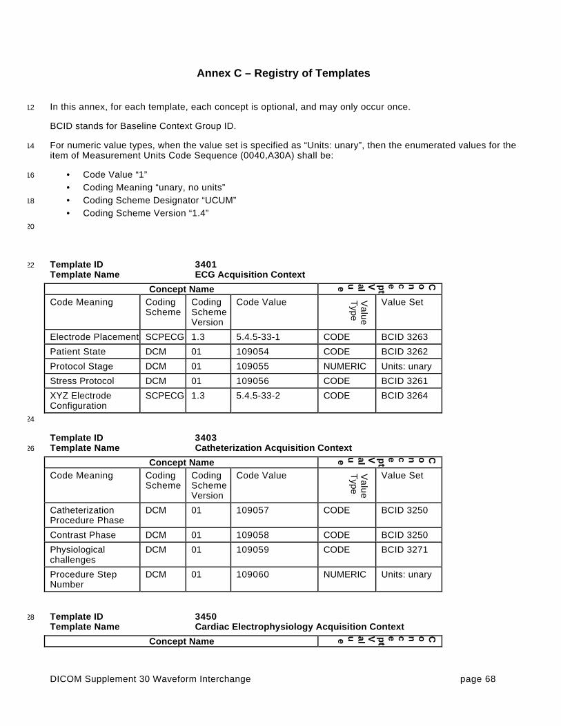
DICOM Supplement 30 Waveform Interchange page 68
Annex C – Registry of Templates
In this annex, for each template, each concept is optional, and may only occur once.12
BCID stands for Baseline Context Group ID.
For numeric value types, when the value set is specified as “Units: unary”, then the enumerated values for the14item of Measurement Units Code Sequence (0040,A30A) shall be:
• Code Value “1”16
• Coding Meaning “unary, no units”• Coding Scheme Designator “UCUM”18
• Coding Scheme Version “1.4”20
Template ID 340122Template Name ECG Acquisition Context
Concept Name
Concept
Value
Code Meaning CodingScheme
CodingSchemeVersion
Code Value Va
lue
Type
Value Set
Electrode Placement SCPECG 1.3 5.4.5-33-1 CODE BCID 3263
Patient State DCM 01 109054 CODE BCID 3262
Protocol Stage DCM 01 109055 NUMERIC Units: unary
Stress Protocol DCM 01 109056 CODE BCID 3261
XYZ ElectrodeConfiguration
SCPECG 1.3 5.4.5-33-2 CODE BCID 3264
24
Template ID 3403Template Name Catheterization Acquisition Context26
Concept Name
Concept
Value
Code Meaning CodingScheme
CodingSchemeVersion
Code Value Va
lue
Type
Value Set
CatheterizationProcedure Phase
DCM 01 109057 CODE BCID 3250
Contrast Phase DCM 01 109058 CODE BCID 3250
Physiologicalchallenges
DCM 01 109059 CODE BCID 3271
Procedure StepNumber
DCM 01 109060 NUMERIC Units: unary
Template ID 345028Template Name Cardiac Electrophysiology Acquisition Context
Concept Name
Concept
Value
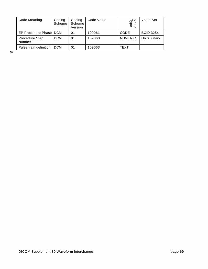
DICOM Supplement 30 Waveform Interchange page 69
Code Meaning CodingScheme
CodingSchemeVersion
Code Value Va
lue
Type
Value Set
EP Procedure Phase DCM 01 109061 CODE BCID 3254
Procedure StepNumber
DCM 01 109060 NUMERIC Units: unary
Pulse train definition DCM 01 109063 TEXT30

DICOM Supplement 30 Waveform Interchange page 70
32
34
36
Changes to:38
NEMA Standards Publication PS 3.11-1999
Digital Imaging and Communications in Medicine (DICOM)40
Part 11: Media Storage Application Profiles
42

DICOM Supplement 30 Waveform Interchange page 71
29. Add new Annex for waveform on 1.44 MB floppy disk44
Annex X (Normative) - Waveform Diskette Interchange Profile
X.1 PROFILE IDENTIFICATION46
This Annex defines a class of Application Profiles for interchange of Waveform SOP Instances via 1.44 MBDiskette (floppy disk) media.48
The identifier for this class shall be STD-WVFM.
The specific Application Profiles in this class are shown in the Table X.1.50
Table X.1 - Waveform Application ProfilesApplication Profile Identifier Description
12-lead ECG Interchange onDiskette
STD-WVFM-ECG-FD Uncompressed ECG waveform data
Hemodynamic WaveformInterchange on Diskette
STD-WVFM-HD-FD Uncompressed hemodynamic waveformdata
52
X.2 CLINICAL CONTEXT
This Application Profile facilitates the interchange of waveforms and related data on floppy disk media.54
This primary clinical context for this profile is the transfer of waveforms, such as electrocardiograms, from non-networked equipment (mobile or remote acquisition units) to archive or display equipment.56
X.2.1 Roles and Service Class Options
This class of Application Profile uses the Media Storage Service Class defined in PS3.4 with the Interchange58Option.
The Application Entity shall support one or more of the roles of File Set Creator (FSC), File Set Reader (FSR),60and File Set Updater (FSU), defined in PS 3.10.
The role of File Set Creator shall be used by Application Entities which generate a File Set under this Class of62Application Profiles. FSCs shall be able to generate the Waveform SOP Instances defined for this ApplicationProfile, and the Basic Directory SOP Instance in the DICOMDIR file with all the subsidiary Directory Records64related to the Waveform SOP Instances stored in the File Set.
The role of File Set Reader shall be used by Application Entities which receive a transferred File Set under66this Class of Application Profiles. File Set Readers shall be able to read the DICOMDIR directory file and allthe SOP Instance files defined for this Application Profile, using the defined Transfer Syntax.68
The role of File Set Updater is used by Application Entities which receive a transferred File Set under thisClass of Application Profiles, and update it by the addition (or deletion) of waveforms or ancillary information70to (or from) the medium. FSUs shall be able to read and update the DICOMDIR file, and optionally togenerate the Waveform SOP Instances defined for this Application Profile.72

DICOM Supplement 30 Waveform Interchange page 72
X.4 STD-WVFM-ECG-FD PROFILE
X.4.1 SOP Classes and Transfer Syntaxes74
This Application Profile is based on the Media Storage Service Class with the Interchange Option (see PS3.4).76
The SOP Classes and corresponding Transfer Syntax supported by this Application Profile are specified in theTable X.4.1-1. The supported Storage SOP Classes shall be listed in the Conformance Statement using a78table of the same form.
Table X.4.1-1 STD-WVFM-ECG-FD SOP Classes and Transfer Syntaxes80
InformationObject Definition
Service ObjectPair Class UID
Transfer Syntax and UID FSCRequire-ment
FSRRequire-ment
FSU
Require-ment
Basic Directory 1.2.840.10008.1.3.10
Explicit VR Little EndianUncompressed
1.2.840.10008.1.2.1
Mandatory Mandatory Mandatory
12-lead ECGWaveformStorage
1.2.840.10008.5.1.4.1.1.9.1.1
Explicit VR Little EndianUncompressed
1.2.840.10008.1.2.1
Mandatory Mandatory Optional
X.4.2 Physical Medium And Medium Format82
The STD-WVFM-ECG-FD application profile requires the 1.44 MB Diskette physical medium with the PC FileSystem Media Format, as defined in PS3.12 Annex B.84
X.4.3 Directory Information in DICOMDIR
Conformant Application Entities shall include in the DICOMDIR File the Basic Directory IOD containing86Directory Records at the Patient and the subsidiary Study and Series levels, appropriate to the SOP Classesin the File Set. All DICOM files in the File Set incorporating SOP Instances defined for the specific Application88Profile shall be referenced by Directory Records.
X.5 STD-WVFM-HD-FD PROFILE90
X.5.1 SOP Classes and Transfer Syntaxes
This Application Profile is based on the Media Storage Service Class with the Interchange Option (see PS923.4).
The SOP Classes and corresponding Transfer Syntax supported by this Application Profile are specified in the94Table X.5.1-1. The supported Storage SOP Classes shall be listed in the Conformance Statement using atable of the same form.96
Table X.5.1-1 STD-WVFM-HD-FD SOP Classes and Transfer SyntaxesInformationObject Definition
Service ObjectPair Class UID
Transfer Syntax and UID FSCRequire-ment
FSRRequire-ment
FSU
Require-ment
Basic Directory 1.2.840.10008.1.3.10
Explicit VR Little EndianUncompressed
1.2.840.10008.1.2.1
Mandatory Mandatory Mandatory
HemodynamicWaveformStorage
1.2.840.10008.5.1.4.1.1.9.2.1
Explicit VR Little EndianUncompressed
1.2.840.10008.1.2.1
Mandatory Mandatory Optional
98

DICOM Supplement 30 Waveform Interchange page 73
X.5.2 Physical Medium And Medium Format
The STD-WVFM-HD-FD application profile requires the 1.44 MB Diskette physical medium with the PC File00System Media Format, as defined in PS3.12 Annex B.
X.5.3 Directory Information in DICOMDIR02
Conformant Application Entities shall include in the DICOMDIR File the Basic Directory IOD containingDirectory Records at the Patient and the subsidiary Study and Series levels, appropriate to the SOP Classes04in the File Set. All DICOM files in the File Set incorporating SOP Instances defined for the specific ApplicationProfile shall be referenced by Directory Records.06


![DICOM Conformance Statement9d48995e-cb8b-4ac4-ae9b... · 2020. 2. 20. · DICOM protocol. 1.5 References [DICOM PS 3 2006] The Digital Imaging and Communications in Medicine (DICOM)](https://img.dokumen.tips/doc/110x75/60e78a442d236e0f92518d06/dicom-conformance-statement-9d48995e-cb8b-4ac4-ae9b-2020-2-20-dicom-protocol.jpg)
![DICOM Conformance Statement - DEKOM Medical€¦ · VR Value Representation 3.7 References [DICOM] The Digital Imaging and Communications in Medicine (DICOM) standard: NEMA PS 3.X](https://img.dokumen.tips/doc/110x75/5ead275852617356c300b375/dicom-conformance-statement-dekom-medical-vr-value-representation-37-references.jpg)