Embed Size (px)
Citation preview

5
Digital Imaging and Communications in Medicine (DICOM)
Supplement 131: Implant Templates
10
15
Prepared by: 20
DICOM Standards Committee, Working Group 24 (Surgery)
1300 N. 17th Street, Suite 1752
Rosslyn, Virginia 22209 USA
25
VERSION: Final Text, November 5, 2010
This supplement is prepared pursuant to work item: 2007-03-B

Supplement 131: Implant Templates Page 2
Table of Contents 30
Table of Contents ........................................................................................................................................... 2 Scope and Field .............................................................................................................................................. 5 Changes to NEMA Standards Publication PS 3.2-2009 ................................................................................ 7 Changes to NEMA Standards Publication PS 3.3-2009 ................................................................................ 9 2 Normative references ............................................................................................................................. 10 35
7.1 DICOM INFORMATION MODEL ..................................................................................................... 10 7.X EXTENSION OF DICOM MODEL OF THE REAL WORLD FOR IMPLANT TEMPLATES ............ 11
A.1.4 Overview of the Composite IOD Module Content ........................................................ 12 A.X GENERIC IMPLANT TEMPLATE INFORMATION OBJECT DEFINITION .......................... 13
A.X.1 Generic Implant Template IOD Description ................................................................. 13 40 A.X.2 Generic Implant Template IOD Entity-Relationship ..................................................... 13 A.X.3 Generic Implant Module IOD Module Table ................................................................ 14
A.Y IMPLANT ASSEMBLY TEMPLATE INFORMATION OBJECT DEFINITION ....................... 14 A.Y.1 Implant Assembly Template IOD Description .............................................................. 14 A.Y.2 Implant Assembly Template IOD Entity Relatonship ................................................... 14 45 A.Y.3 Implant Assembly Template IOD Module Table .......................................................... 15
A.Z IMPLANT TEMPLATE GROUP INFORMATION OBJECT DEFINITION .............................. 15 A.Z.1 Implant Template Group IOD Description.................................................................... 15 A.Z.2 Implant template Group IOD Entity Relationship ......................................................... 15 A.Z.3 Implant Template Group IOD Module Table ................................................................ 16 50
C.X GENERIC IMPLANT TEMPLATE .......................................................................................... 16 C.X.1 Generic Implant Template Description Module ........................................................... 16
C.X.1.1 Generic Implant Template Description Attribute Descriptions ........................... 19 C.X.1.1.1 Implant Size ............................................................................. 19 C.X.1.1.2 Frame of Reference ................................................................. 19 55
C.X.2 Generic Implant Template 2D Drawings Module ......................................................... 19 C.X.2.1 Generic Implant Template 2D Drawings Attribute Descriptions ........................ 20
C.X.2.1.1 HPGL Document Scaling and Coordinate System .................. 20 C.X.2.1.2 HPGL Document ...................................................................... 21
C.X.2.1.2.1 Scope ........................................................................................... 21 60 C.X.2.1.2.2 Syntax .......................................................................................... 21
C.X.3 Generic Implant Template 3D Models Module ............................................................ 23 C.X.3.1 Generic Implant Template 3D Models Attribute Descriptions ............................ 23
C.X.3.1.1 Surface Model Scaling Factor .................................................. 23 C.X.4 Generic Implant Template Mating Features Module ................................................... 23 65
C.X.4.1 Generic Implant Template 2D Drawings Attribute Descriptions ........................ 26 C.X.4.1.1 Mating Features ....................................................................... 26 C.X.4.1.2 Degrees of Freedom ............................................................... 26
C.X.5 Generic Implant Template Planning Landmarks Module ............................................ 26 C.X.5.1 Planning Landmark Macros ............................................................................... 28 70
C.X.5.1.1 Planning Landmark Macros Attribute Descriptions .................. 30 C.X.5.1.1.1 2D Coordinates Sequences ......................................................... 30
C.Y IMPLANT ASSEMBLY TEMPLATE ....................................................................................... 31 C.Y.1 Implant Assembly Template Module ............................................................................ 31
C.Y.1.1 Implant Assembly Template Module Attribute Description ................................ 34 75 C.Y.1.1.1 Component Assembly Sequence ............................................. 34

Supplement 131: Implant Templates Page 3
C.Z IMPLANT TEMPLATE GROUP MODULE ...................................................................................... 34 C.Z.1 Implant Template Group Module ................................................................................. 34
C.Z.1.1 Implant Template Group Module Attribute Description ...................................... 36 C.Z.1.1.1 Implant Template Group Member Matching Coordinates ........ 36 80 C.Z.1.1.2 Implant Template Groups ........................................................................... 37
F.5.X Implant directory record definition ................................................................................ 41 F.5.Y Implant Assembly directory record definition ............................................................... 41 F.5.Z Implant Group directory record definition..................................................................... 41
Changes to NEMA Standards Publication PS 3.4-2009 .............................................................................. 43 85
B.5 STANDARD SOP CLASSES ............................................................................................... 44 B.5.1.x Implant Template Storage SOP Classes ........................................................... 44
I.4 MEDIA STORAGE STANDARD SOP CLASSES................................................................ 45 Annex Y IMPLANT TEMPLATE QUERY/RETRIEVE SERVICE CLASSES ........................................ 46
Y.1 OVERVIEW ............................................................................................................................ 46 90
Y.1.1 Scope ........................................................................................................................... 46 Y.1.2 Conventions ................................................................................................................. 46 Y.1.3 Query/Retrieve Information Model ............................................................................... 46 Y.1.4 Service Definition ......................................................................................................... 46
Y.2 IMPLANT TEMPLATE INFORMATION MODELS DEFINITIONS......................................... 47 95
Y.3 IMPLANT TEMPLATE INFORMATION MODELS ................................................................ 47 Y.4 DIMSE-C SERVICE GROUPS .............................................................................................. 47
Y.4.1 C-FIND Operation ........................................................................................................ 47 Y.4.1.1 Service Class User Behavior ............................................................................. 47 Y.4.1.2 Service Class Provider Behavior ....................................................................... 47 100
Y.4.2 C-MOVE Operation ...................................................................................................... 47 Y.4.3 C-GET Operation ......................................................................................................... 48
Y.5 ASSOCIATION NEGOTIATION ............................................................................................ 48 Y.6 SOP CLASS DEFINITIONS ................................................................................................... 48
Y.6.1 Implant Template Information Model ........................................................................... 48 105 Y.6.1.1 E/R Models ......................................................................................................... 48 Y.6.1.2 Implant Template Attributes .............................................................................. 49
Y.6.1.2.1 Generic Implant Template Attributes ....................................... 49 Y.6.1.2.2 Implant Assembly Template Attributes .................................... 50 Y.6.1.2.3 Implant Template Group Attributes .......................................... 51 110
Y.6.1.3 Conformance Requirements .............................................................................. 52 Y.6.1.3.1 SCU Conformance ................................................................... 52
Y.6.1.3.1.1 C-FIND SCU Conformance ......................................................... 52 Y.6.1.3.1.2 C-MOVE SCU Conformance ....................................................... 53 Y.6.1.3.1.3 C-GET SCU Conformance .......................................................... 53 115
Y.6.1.3.2 SCP Conformance ................................................................... 53 Y.6.1.3.2.1 C-FIND SCP Conformance .......................................................... 53 Y.6.1.3.2.2 C-MOVE SCP Conformance ....................................................... 53 Y.6.1.3.2.3 C-GET SCP Conformance ........................................................... 53
Y.6.1.4 SOP Classes ..................................................................................................... 53 120
Changes to NEMA Standards Publication PS 3.6-2009 .............................................................................. 55 6 Registry of DICOM data elements ......................................................................................................... 56 Annex A Registry of DICOM unique identifiers (UID) (Normative) ...................................................... 59 Changes to NEMA Standards Publication PS 3.15-2009 ............................................................................ 61
C.2 CREATOR RSA DIGITAL SIGNATURE PROFILE ............................................................... 62 125
C.3 AUTHORIZATION RSA DIGITAL SIGNATURE PROFILE ................................................... 62

Supplement 131: Implant Templates Page 4
Changes to NEMA Standards Publication PS 3.16-2009 ............................................................................ 63 CID 7300 IMPLANT MATERIALS ................................................................................................ 64 CID 7301 INTERVENTION TYPES ............................................................................................. 64 CID 7302 IMPLANT TEMPLATES VIEW ORIENTATIONS ......................................................... 64 130
CID 7303 IMPLANT TEMPLATES MODIFIED VIEW ORIENTATIONS ...................................... 65 CID 7304 IMPLANT TARGET ANATOMY ................................................................................... 65 CID 7305 IMPLANT PLANNING LANDMARKS .......................................................................... 66 CID 7306 HUMAN HIP IMPLANT PLANNING LANDMARKS ..................................................... 66 CID 7307 IMPLANT COMPONENT TYPES ................................................................................ 67 135
CID 7308 HUMAN HIP IMPLANT TYPES ................................................................................... 67 CID 7309 HUMAN TRAUMA IMPLANT TYPES .......................................................................... 67 CID 7310 IMPLANT FIXATION METHOD ................................................................................... 68
Changes to NEMA Standards Publication PS 3.17-2009 ............................................................................ 74 X Implant Template Description ................................................................................................................ 75 140
X.1 IMPLANT MATING ................................................................................................................ 75 X.1.1 Mating Features ........................................................................................................... 75 X.1.2 Mating Feature ID ........................................................................................................ 75 X.1.3 Mating Feature Sets ..................................................................................................... 76 X.1.4 Degrees of Freedom .................................................................................................... 77 145 X.1.5 Implant Assembly Templates ....................................................................................... 77
X.2 PLANNING LANDMARKS ..................................................................................................... 78 X.3 IMPLANT REGISTRATION AND MATING EXAMPLE ......................................................... 78
X.3.1 Degrees Of Freedom ................................................................................................... 81 X.4 ENCODING EXAMPLE ......................................................................................................... 82 150
X.5 IMPLANT TEMPLATE VERSIONS AND DERIVATION ........................................................ 86

Supplement 131: Implant Templates Page 5
Scope and Field
This supplement describes storage, query and retrieval of implant templates (generally non-patient-specific) as they are used in implantation planning. The supplement contains 155 a generic IOD for implants of an unspecified type and an IOD that describes assemblies of implant components for specific surgical use cases.
The Generic Implant Template IOD is used to encode the description of a specific surgical implant (vendor, type, serial number), its shape and planning landmarks used to register them with patient images. Together with the Implant Assembly Template IOD 160 these IODs describe how multiple components are to be assembled.
The associated Service Classes support the storage (C-STORE), query (C-FIND), and retrieve (C-MOVE), (C-GET) of Implant Template Instances between servers and workstations.
3D templates are described using the Surface Mesh Module while 2D templates are 165 described by encapsulated documents that comply with a subset of HPGL, which is specified within this Supplement.
The Generic Implant Template IOD supports the following features:
— An Implant IOD Instance contains information about one physical part of an implant. If implants consist of several components, each component will be 170 represented in a separate Instance.
— Implant Template Instances (can) contain information about:
o Manufacturer, Name, Part Number, …
o Shape
o Indication 175
o Coordinate Systems that can be used to match one implant with another implant in an assembly
o Anatomical Landmarks
— Query for Implant Templates is possible by name, manufacturer, body part, and other Attributes. 180
The Implant Assembly Templates IOD supports the following features:
— It references several Implant Template Instances and provides a list of possible combinations between the represented implants.
— By referencing Mating Feature in the Implant Template Instances the spatial relation between compatible components after the assembly is described. 185
— Query for Implant Assembly Templates are possible by name, manufacturer, intervention type, target anatomy, and other Attributes.
The Implant Template Group IOD supports the following features:
— It references several Implant Template Instances and provides dimensions according to which the templates can be ordered. 190

Supplement 131: Implant Templates Page 6
— Defines a common coordinate system according to which all templates in a group can be roughly aligned.
— Query for Implant Template Groups are possible by name, issuer, intervention type, target anatomy, and other Attributes.
The associated Service Classes support the storage (C-STORE), query (C-FIND), and retrieve 195 (C-MOVE), (C-GET) of Implant Assembly Template Instances between servers and workstations.

Supplement 131: Implant Templates Page 7
200
Changes to NEMA Standards Publication PS 3.2-2009 205
Digital Imaging and Communications in Medicine (DICOM)
Part 2: Conformance

Supplement 131: Implant Templates Page 8
Item: Add SOP Class to Table A.1-2
Table A.1-2 210 UID VALUES
UID Value UID NAME Category … 1.2.840.10008.5.1.4.43.1 Gener ic Implant Template
Storage Transfer
1.2.840.10008.5.1.4.43.2 Gener ic Implant Template Information Model – FIND
Query / Retrieve
1.2.840.10008.5.1.4.43.3 Gener ic Implant Template Information Model – MOVE
Query / Retrieve
1.2.840.10008.5.1.4.43.4 Gener ic Implant Template Information Model – GET
Query / Retrieve
1.2.840.10008.5.1.4.44.1 Implant Assembly Template Storage
Transfer
1.2.840.10008.5.1.4.44.2 Implant Assembly Template Information Model – FIND
Query / Retrieve
1.2.840.10008.5.1.4.44.3 Implant Assembly Template Information Model – MOVE
Query / Retrieve
1.2.840.10008.5.1.4.44.4 Implant Assembly Template Information Model – GET
Query / Retrieve
1.2.840.10008.5.1.4.45.1 Im plant Template Group Storage
Transfer
1.2.840.10008.5.1.4.45.2 Im plant Template Group Information Model – FIND
Query / Retrieve
1.2.840.10008.5.1.4.45.3 Im plant Template Group Information Model – MOVE
Query / Retrieve
1.2.840.10008.5.1.4.45.4 Im plant Template Group Information Model – GET
Query / Retrieve
…

Supplement 131: Implant Templates Page 9
215
220
Changes to NEMA Standards Publication PS 3.3-2009
Digital Imaging and Communications in Medicine (DICOM)
Part 3: Information Object Definitions
225
Supplement 131: Implant Templates Page 10
Item: Add In Section 2
2 Normative references
HPGL HEWLETT PACKARD PCL/PJL Reference PCL5 Printer Language Technical Reference Manual Part II HP Part No. 5961-0509 230 URL: http://h20000.www2.hp.com/bc/docs/support/SupportManual/bpl13211/bpl13211.pdf.
Item: Add In Section 7
Generic Implant
Template IOD
1,n
Implant Assembly
Template IOD
references
0,n
Implant Template
Group IOD
references
0,n
1,n
235
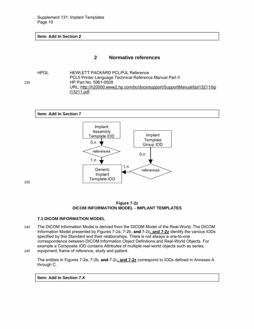
Figure 7-2z DICOM INFORMATION MODEL - IMPLANT TEMPLATES
7.1 DICOM INFORMATION MODEL
The DICOM Information Model is derived from the DICOM Model of the Real-World. The DICOM 240 Information Model presented by Figures 7-2a, 7-2b, and 7-2c, and 7-2z identify the various IODs specified by this Standard and their relationships. There is not always a one-to-one correspondence between DICOM Information Object Definitions and Real-World Objects. For example a Composite IOD contains Attributes of multiple real-world objects such as series, equipment, frame of reference, study and patient. 245
The entities in Figures 7-2a, 7-2b, and 7-2c, and 7-2z correspond to IODs defined in Annexes A through C.
Item: Add In Section 7.X

Supplement 131: Implant Templates Page 11
7.X EXTENSION OF DICOM MODEL OF THE REAL WORLD FOR IMPLANT TEMPLATES
For the purpose of Implant Template SOP Classes the DICOM Model of the Real-World is 250 described in this section. This subset of the real-world model covers the requirements for the planning of surgical implantation of implants using 2D and/or 3D templates. In this context, a Manufacturer may be a company, an institution or a person that issues Implant Templates.
Figures 7.X-1 is an abstract description of the real world objects involved in Implant Templates.
255
Implant
Manufacturer produces
1,n1
issues1,n1
Implant Template
represents
1,n
1
Figure 7.X-1 IMPLANT TEMPLATE MODEL OF THE REAL WORLD
Implant Template
1,n
Implant Assembly
Template
contains
0,n

Supplement 131: Implant Templates Page 12
Figure 7.X-2 260 IMPLANT ASSEMBLY TEMPLATE MODEL OF THE REAL WORLD
Implant Template
1,n
Implant Template Group
contains
0,n
Implant Template Group Variation
Dimension
1,n
defines
0,n
1,ncontains
0,n
Figure 7.X-3 IMPLANT TEMPLATE GROUP MODEL OF THE REAL WORLD 265
Item: Add in Section A.1.4, rows and column to Table A.1-2
A.1.4 Overview of the Composite IOD Module Content
IODs Modules
Generic Implant
Template
Implant Assembly Template
Implant Template
Group Generic Implant Template Description
M
Generic Implant Template 2D Drawings
C
Generic Implant Template 3D Models
C
Generic Implant Template Mating Features
U

Supplement 131: Implant Templates Page 13
Generic Implant Template Planning Landmarks
U
Implant Assembly Template
M
Implant Template Group
M
SOP Common M M M Surface Mesh U
Item: Add in the following new section in Annex A 270
A.X GENERIC IMPLANT TEMPLATE INFORMATION OBJECT DEFINITION
A.X.1 Generic Implant Template IOD Description The Generic Implant Template Information Object Definition (IOD) specifies the description of a 2D- and/or 3D-template representing a rigid and passive implant. The specific properties of flexible implants, such as silicone implants, and active implants such as cardiac pacemakers are 275 not reflected. The IOD contains mechanisms for implant assembly, i.e. the rigid connection of two or more implants and implant registration, i.e. the placement of an implant in relation to anatomical landmarks.
The Generic Implant Template is a kind of Implant Template (see Section 7.X).
A.X.2 Generic Implant Template IOD Entity-Relationship 280
The E-R Model in Figure A.X-1 depicts those entities of the DICOM Information Model that that are used in the following IODs.
Implant Template
contains
1
0,n
Surface Mesh
Figure A.X-1 GENERIC IMPLANT TEMPLATE IOD INFORMATION MODEL 285
Note: Implant templates are not referenced to a patient, a study or a series.

Supplement 131: Implant Templates Page 14
A.X.3 Generic Implant Module IOD Module Table Implant Templates can contain 2D drawings as well as 3D models describing one implant. At least one of the two must be present in one Instance; both may be present in the same Instance.
Table A.X-1 290 GENERIC IMPLANT TEMPLATE IOD MODULES
IE Module Reference Usage Implant Template
Generic Implant Template Description
C.X.1 M
Generic Implant Template 2D Drawings
C.X.2 U
Generic Implant Template 3D Models
C.X.3 U
Generic Implant Template Mating Features
C.X.4 U
Generic Implant Template Planning Landmarks
C.X.5 U
SOP Common C.12.1 M Surface Mesh Surface Mesh C.27.1 C - Required if Generic Implant
Template 3D Models Module is present.
A.Y IMPLANT ASSEMBLY TEMPLATE INFORMATION OBJECT DEFINITION
A.Y.1 Implant Assembly Template IOD Description Implant Assembly Templates describe how to combine several implants to fulfill a certain 295 purpose. The Implant Assembly Templates describe the aspects of component assembly that are relevant to planning only. Implants that are made out of several parts but are treated as a single piece may be described as single Implant Template.
A.Y.2 Implant Assembly Template IOD Entity Relatonship The E-R Model in Figure A.Y-1 depicts those entities of the DICOM Information Model that are 300 used in the following IODs.
Implant Template
1,n
Implant Assembly Template
references
0,n

Supplement 131: Implant Templates Page 15
Figure A.Y-1 IMPLANT ASSEMBLY TEMPLATE IOD INFORMATION MODEL 305
A.Y.3 Implant Assembly Template IOD Module Table Table A.Y-1
IMPLANT ASSEMBLY TEMPLATE IOD MODULES IE Module Reference Usage Implant Assembly
Implant Assembly Template
C.Y M
SOP Common C.12.1 M
310
A.Z IMPLANT TEMPLATE GROUP INFORMATION OBJECT DEFINITION
A.Z.1 Implant Template Group IOD Description The Implant Template Group IOD facilitates the aggregation of a set of Implant Template Instances in an ordered set.
A.Z.2 Implant template Group IOD Entity Relationship 315
The E-R Model in Figure A.Z-1 depicts those entities of the DICOM Information Model that are used in the following IODs.
Implant Template
Spatially defines
Frame of Reference
1,n
0,n contains
1
1,n
Implant Assembly Template
references
0,n
0,n
Surface Mesh
Implant Template
Group
references
0,n
1,n
Figure A.Z-1 320 IMPLANT TEMPLATE GROUP IOD INFORMATION MODEL

Supplement 131: Implant Templates Page 16
A.Z.3 Implant Template Group IOD Module Table Table A.Z-1
IMPLANT TEMPLATE GROUP IOD MODULES 325
IE Module Reference Usage Implant Template Group
Implant Template Group
C.Z M
SOP Common C.12.1 M
Item: Add in the following new sections in C
C.X GENERIC IMPLANT TEMPLATE
This section describes the specific modules for the Generic Implant Template IOD.
C.X.1 Generic Implant Template Description Module 330
Table C.X.1-1 defines the general Attributes of the Generic Implant Template Description Module.
Table C.X.1-1 GENERIC IMPLANT TEMPLATE DESCRIPTION MODULE ATTRIBUTES
Attribute Name Tag Type Attribute Description Manufacturer (0008,0070) 1 Name of the manufacturer that produces
the implant. Frame of Reference UID (0020,0052) 1 Defines a 3D Frame of Reference for this
component. Implant Name (0022,1095) 1 The (product) name of the implant. Implant Size (0068,6210) 1C The size descriptor of the component.
Required if the component exists in different sizes and the size number is not part of the name or identifier. May be present otherwise. See C.X.1.1.1 for details.
Implant Part Number (0022,1097) 1 The (product) identifier of the implant. Implant Template Version (0068,6221) 1 The version code of the implant
template. If Implant Type (0068,6223) is DERIVED, this shall have the same value as the Implant Template Version (0068,6221) of the manufacturer’s implant template from which this instance was derived.
Replaced Implant Template Sequence
(0068,6222) 1C Reference to the Implant Template which is replaced by this template. Required if this Instance replaces another Instance. Only one Item shall be present.
>Include ‘SOP Instance Reference Macro’ Table 10-11

Supplement 131: Implant Templates Page 17
Implant Type (0068,6223) 1 Indicates whether the Implant Template is derived from another Implant Template. Enumerated Values: ORIGINAL DERIVED
Original Implant Template Sequence
(0068,6225) 1C Reference to the Implant Template Instance with Implant Type (0068,6223) ORIGINAL from which this Instance was ultimately derived. Required if Implant Type (0068,6223) is DERIVED. Only one Item shall be present.
>Include ‘SOP Instance Reference Macro’ Table 10-11 Derivation Implant Template Sequence
(0068,6224) 1C Reference to Implant Template Instance from which this Instance was directly derived. Required if Implant Type (0068,6223) is DERIVED. Only one Item shall be present.
>Include ‘SOP Instance Reference Macro’ Table 10-11 Effective DateTime (0068,6226) 1 Date and time from which this Instance is
or will be valid. Implant Target Anatomy Sequence
(0068,6230) 3 Sequence that identifies the anatomical region the implant is to be implanted to. One or more Items shall be present.
>Anatomic Region Sequence (0008,2218) 1 Sequence that identifies the anatomic region of interest in this Instance (i.e. external anatomy, surface anatomy, or general region of the body). Only a single Item shall be permitted in this sequence.
>>Include ‘Code Sequence Macro’ Table 8.8-1 Defined Context ID 7304 Implant Target Anatomy Notification From Manufacturer Sequence
(0068,6265) 1C Information from the manufacturer concerning a critical notification, recall, or discontinuation of the implant or implant template. Required if such information has been issued. One or more Items shall be present.
>Information Issue DateTime (0068,6270) 1 Date and Time the information was issued.
>Information Summary (0068,6280) 1 Summary of the information. >Encapsulated Document (0042,0011) 3 The complete manufacturer notification
describing the template. Encapsulated Document stream, containing a document encoded according to the MIME Type.

Supplement 131: Implant Templates Page 18
>MIME Type of Encapsulated Document
(0042,0012) 1C The type of the encapsulated document stream described using the MIME Media Type (see RFC 2046). Required if Encapsulated Document (0042,0011) is present in this Sequence item. Enumerated Value shall be “application/pdf”.
Information From Manufacturer Sequence
(0068,6260) 3 Information from Manufacturer other than described in Notification From Manufacturer Sequence (0068,6265). One or more Items shall be present in the sequence.
>Information Issue DateTime (0068,6270) 1 Date and Time the information was issued.
>Information Summary (0068,6280) 1 Summary of the information. >Encapsulated Document (0042,0011) 3 Encapsulated Document stream,
containing a document encoded according to the MIME Type. The complete manufacturer information.
>MIME Type of Encapsulated Document
(0042,0012) 1C The type of the encapsulated document stream described using the MIME Media Type (see RFC 2046). Required if Encapsulated Document (0042,0011) is present in this Sequence item. Enumerated Value shall be “application/pdf”.
Implant Regulatory Disapproval Code Sequence
(0068,62A0) 1C Sequence containing countries and regions in which the implant is not approved for usage. Required if the implant has been disapproved in a country or a region. If present, one or more Items shall be present in the sequence.
>Include ‘Code Sequence Macro’ Table 8.8-1 Defined Context ID is 5001. Overall Template Spatial Tolerance
(0068,62A5) 2 Tolerance in mm applying to all distance measurements and spatial locations in this Implant Template.
Materials Code Sequence (0068,63A0) 1 A code sequence specifying the materials the implant was built from. One or more Items shall be present in the Sequence.
>Include ‘Code Sequence Macro’ Table 8.8-1 Baseline Context ID is 7300.

Supplement 131: Implant Templates Page 19
Coating Materials Code Sequence
(0068,63A4) 1C Required if the implant is coated. A code sequence specifying the materials the implant is coated with. One or more Items shall be present in the Sequence.
>Include ‘Code Sequence Macro’ Table 8.8-1 Baseline Context ID is 7300. Implant Type Code Sequence (0068,63A8) 1 Sequence containing a coded description
of the type of implant the template reflects.
>Include ‘Code Sequence Macro’ Table 8.8-1 Baseline Context ID is 7307. Fixation Method Code Sequence
(0068,63AC) 1 The method which will be used to fixate the implant in the body. Only a single Item shall be permitted in this sequence.
>Include ‘Code Sequence Macro’ Table 8.8.1 Baseline Context ID 7310 335
C.X.1.1 Generic Implant Template Description Attribute Descriptions C.X.1.1.1 Implant Size The Implant Size (0068,6210) is the descriptor defined by the manufacturer to distinguish between different sizes of one kind of implant, e.g. size S/M/L/XL.
C.X.1.1.2 Frame of Reference 340
The Frame of Reference UID (0020,0052) Attribute is used as an identifier for spatial registration in 3D. The Frame Of Reference UID uniquely identifies the spatial frame of reference of all 3D models contained in an Implant Template UID Instance.
If the Frame Of Reference UIDs in two instances are identical, the contained 3D Models are defined in the same 3D space, i.e. require no additional registration. 345
C.X.2 Generic Implant Template 2D Drawings Module Table C.X.2-1 defines the general Attributes of the Generic Implant Template 2D Drawings Module. This module contains all Attributes required for the inclusion of technical 2D drawings in an IOD, e.g. the Implant Template IOD. The module specification contains the definition of a 350 subset of the HPGL plotter language which is used for the graphical definition of the drawings.
Table C.X.2-1 GENERIC IMPLANT TEMPLATE 2D DRAWINGS MODULE ATTRIBUTES
Attribute Name Tag Type Attribute Description HPGL Document Sequence (0068,62C0) 1 The 2D template representations of this
implant. One or more Items shall be present in the sequence.
>HPGL Document ID (0068,62D0) 1 Identification number of the HPGL Document. Uniquely identifies an HPGL Document within this SOP instance. The value shall start at 1, and increase monotonically by 1.
Supplement 131: Implant Templates Page 20
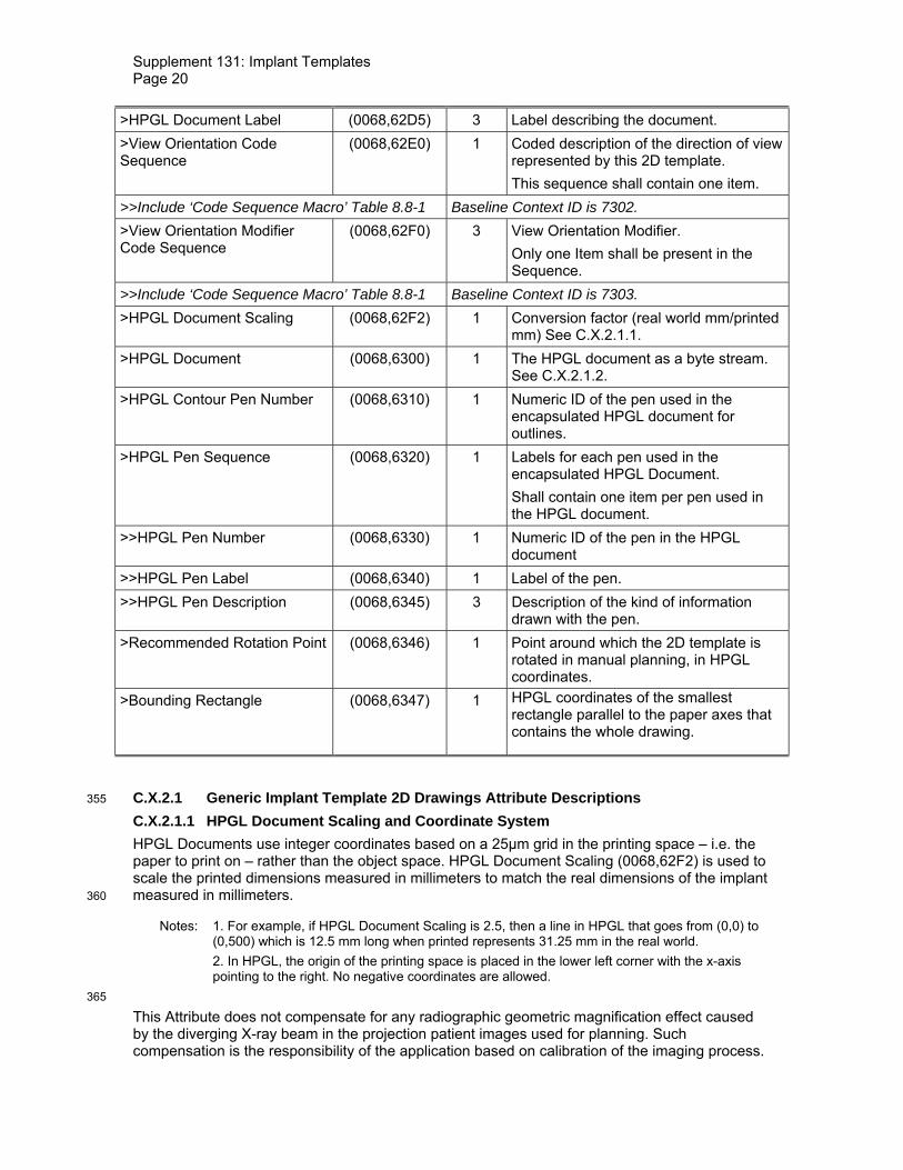
>HPGL Document Label (0068,62D5) 3 Label describing the document. >View Orientation Code Sequence
(0068,62E0) 1 Coded description of the direction of view represented by this 2D template. This sequence shall contain one item.
>>Include ‘Code Sequence Macro’ Table 8.8-1 Baseline Context ID is 7302. >View Orientation Modifier Code Sequence
(0068,62F0) 3 View Orientation Modifier. Only one Item shall be present in the Sequence.
>>Include ‘Code Sequence Macro’ Table 8.8-1 Baseline Context ID is 7303. >HPGL Document Scaling (0068,62F2) 1 Conversion factor (real world mm/printed
mm) See C.X.2.1.1. >HPGL Document (0068,6300) 1 The HPGL document as a byte stream.
See C.X.2.1.2. >HPGL Contour Pen Number (0068,6310) 1 Numeric ID of the pen used in the
encapsulated HPGL document for outlines.
>HPGL Pen Sequence (0068,6320) 1 Labels for each pen used in the encapsulated HPGL Document. Shall contain one item per pen used in the HPGL document.
>>HPGL Pen Number (0068,6330) 1 Numeric ID of the pen in the HPGL document
>>HPGL Pen Label (0068,6340) 1 Label of the pen. >>HPGL Pen Description (0068,6345) 3 Description of the kind of information
drawn with the pen. >Recommended Rotation Point (0068,6346) 1 Point around which the 2D template is
rotated in manual planning, in HPGL coordinates.
>Bounding Rectangle (0068,6347) 1 HPGL coordinates of the smallest rectangle parallel to the paper axes that contains the whole drawing.
C.X.2.1 Generic Implant Template 2D Drawings Attribute Descriptions 355
C.X.2.1.1 HPGL Document Scaling and Coordinate System HPGL Documents use integer coordinates based on a 25µm grid in the printing space – i.e. the paper to print on – rather than the object space. HPGL Document Scaling (0068,62F2) is used to scale the printed dimensions measured in millimeters to match the real dimensions of the implant measured in millimeters. 360
Notes: 1. For example, if HPGL Document Scaling is 2.5, then a line in HPGL that goes from (0,0) to (0,500) which is 12.5 mm long when printed represents 31.25 mm in the real world.
2. In HPGL, the origin of the printing space is placed in the lower left corner with the x-axis pointing to the right. No negative coordinates are allowed.
365
This Attribute does not compensate for any radiographic geometric magnification effect caused by the diverging X-ray beam in the projection patient images used for planning. Such compensation is the responsibility of the application based on calibration of the imaging process.
Supplement 131: Implant Templates Page 21
C.X.2.1.2 HPGL Document The HPGL files encapsulated in the Attribute HPGL Document (0068,6300) is restricted to a 370 subset of HPGL commands called DICOM-HPGL specified in this section.
C.X.2.1.2.1 Scope The aim of DICOM-HPGL is to facilitate the storage of 2D template graphics in DICOM implant objects. DICOM-HPGL is a subset of HPGL-2 that is kept as minimal as possible to comply with the needs of 2D implant templates. 375
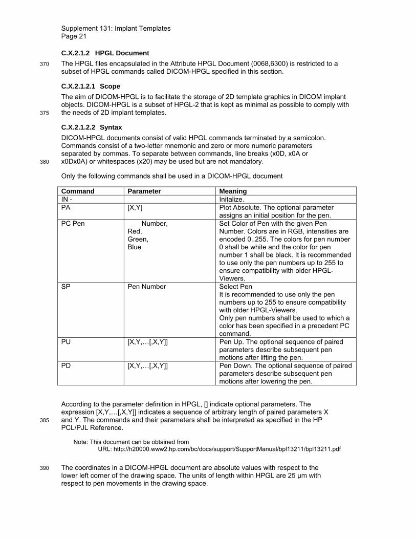
C.X.2.1.2.2 Syntax DICOM-HPGL documents consist of valid HPGL commands terminated by a semicolon. Commands consist of a two-letter mnemonic and zero or more numeric parameters separated by commas. To separate between commands, line breaks (x0D, x0A or x0Dx0A) or whitespaces (x20) may be used but are not mandatory. 380
Only the following commands shall be used in a DICOM-HPGL document
Command Parameter Meaning IN - Initalize. PA [X,Y] Plot Absolute. The optional parameter
assigns an initial position for the pen. PC Pen Number,
Red, Green, Blue
Set Color of Pen with the given Pen Number. Colors are in RGB, intensities are encoded 0..255. The colors for pen number 0 shall be white and the color for pen number 1 shall be black. It is recommended to use only the pen numbers up to 255 to ensure compatibility with older HPGL-Viewers.
SP Pen Number Select Pen It is recommended to use only the pen numbers up to 255 to ensure compatibility with older HPGL-Viewers. Only pen numbers shall be used to which a color has been specified in a precedent PC command.
PU [X,Y,…[,X,Y]] Pen Up. The optional sequence of paired parameters describe subsequent pen motions after lifting the pen.
PD [X,Y,…[,X,Y]] Pen Down. The optional sequence of paired parameters describe subsequent pen motions after lowering the pen.
According to the parameter definition in HPGL, [] indicate optional parameters. The expression [X,Y,…[,X,Y]] indicates a sequence of arbitrary length of paired parameters X and Y. The commands and their parameters shall be interpreted as specified in the HP 385 PCL/PJL Reference.
Note: This document can be obtained from URL: http://h20000.www2.hp.com/bc/docs/support/SupportManual/bpl13211/bpl13211.pdf
The coordinates in a DICOM-HPGL document are absolute values with respect to the 390 lower left corner of the drawing space. The units of length within HPGL are 25 µm with respect to pen movements in the drawing space.

Supplement 131: Implant Templates Page 22
The DICOM-HPGL Document shall be structured as shown in Figure C.X.2-1.
Figure X-1.2 shows an example for a DICOM-HPGL Document in plain text, (as byte stream) and plotted. 395
Figure C.X.2-1 DICOM-HPGL Document
Figure C.X.2-2 400 DICOM-HPGL Document – Example
IN
PA
PC
SP
PD PU
IN; PA; PC2,255,0,0; PC255,0,255,0; SP2; PU500,500; PD745,255,255,255; PD500,500; SP255; PU500,600; PD500,100;

Supplement 131: Implant Templates Page 23
C.X.3 Generic Implant Template 3D Models Module Table C.X.3-1 defines the general Attributes of the Generic Implant Template 3D Models Module. This module contains Attributes that add context and scaling information to surfaces specified in the Surface Mesh Module (C.27.1), for 3D Models in an Implant Template Instance. 405
Table C.X.3-1
GENERIC IMPLANT TEMPLATE 3D MODELS MODULE ATTRIBUTES Attribute Name Tag Type Attribute Description Implant Template 3D Model Surface Number
(0068,6350) 1 Surface Number (0066,0003) of the surface that represents the shape of the entire implant.
Surface Model Description Sequence
(0068,6360) 1 The description of the Surface Model. Shall contain one Item per Item in the Surface Sequence (0066,0002).
>Referenced Surface Number (0066,002C) 1 Reference to a Surface Number (0066,0003) present in the Surface Sequence (0066,0002).
>Surface Model Label (0068,6380) 1 Label for this surface. Surface Model Scaling Factor (0068,6390) 1 Scaling factor (mm/Surface unit)
See C.X.3.1.1. C.X.3.1 Generic Implant Template 3D Models Attribute Descriptions 410
C.X.3.1.1 Surface Model Scaling Factor Surface Model Scaling Factor (0068,6390) is used to scale dimensions of the surface mesh representation to match the real dimensions of the implant measured in millimeters.
This Attribute does not compensate for any radiographic geometric magnification effect caused by the diverging X-ray beam in the projection patient images used for planning. Such 415 compensation is the responsibility of the application based on calibration of the imaging process.
C.X.4 Generic Implant Template Mating Features Module Table C.X.4-1 defines the general Attributes of the Generic Implant Template Mating Features Module. This module adds coordinate systems which can be utilized to geometrically constrain mating of Implant Templates when planning the implantation of a modular implant. 420
Note: An Implant Template may contain 2D drawings of the described implant, 3D surface models of the described implant, or both. In this module mating features which constrain the geometric matching of implants in multi-component assemblies are specified. These geometric features (points and axes) can be specified in the 2D drawings as well as the 3D models. Mating features are grouped into mating feature sets (see PS3.17 X.1). Based on the existence of 2D 425 drawings and/or 3D models in the Instance, either or both is possible. In this module, there are a number of conditions on attribute use to support the following cases:
• Specification of 2D mating features is only possible if at least one 2D drawing is present in the instance.
• Specification of 3D mating features is only possible if at least one 3D model is 430 present in the instance.
Table C.X.4-1
GENERIC IMPLANT TEMPLATE MATING FEATURES MODULE ATTRIBUTES Attribute Name Tag Type Attribute Description

Supplement 131: Implant Templates Page 24
Mating Feature Sets Sequence (0068,63B0) 3 Mating feature sets used to combine the implant with other implants. One or more Items shall be present in the Sequence.
>Mating Feature Set ID (0068,63C0) 1 Identification number of the set. Uniquely identifies a mating feature set within this SOP instance. The value shall start at 1, and increase monotonically by 1 for each Item.
>Mating Feature Set Label (0068,63D0) 1 Label of the set. >Mating Feature Sequence (0068,63E0) 1 The mating features of the set.
One or more Items shall be present in the Sequence.
>>Mating Feature ID (0068,63F0) 1 Numeric ID of the mating feature. Uniquely identifies a mating feature within this Sequence Item.
>>3D Mating Point (0068,64C0) 1C Origin of the contact system. Required if 2D Mating Feature Coordinates Sequence (0068,6430) is not present and Implant Template 3D Model Surface Number (0068,6350) is present. May be present if 2D Mating Feature Coordinates Sequence (0068,6430) is present and Implant Template 3D Model Surface Number (0068,6350) is present. See C.X.4.1.1
>>3D Mating Axes (0068,64D0) 1C The Axes of contact described as direction cosines in the 3D coordinate system defined by the Frame Of Reference UID. Required if 3D Mating Point (0068,64C0) is present. See C.X.4.1.1
>>2D Mating Feature Coordinates Sequence
(0068,6430) 1C Coordinates of the mating feature in the HPGL documents. Required if 3D Mating Point (0068,64C0) is not present and HPGL Document Sequence (0068,62C0) is present. May be present if 3D Mating Point (0068,64C0) is present and HPGL Document Sequence (0068,62C0) is present. One or more Items shall be present in the sequence.

Supplement 131: Implant Templates Page 25
>>>Referenced HPGL Document ID
(0068,6440) 1 Value of the HPGL Document ID (0068,62D0) present in the HPGL Document Sequence (0068,62C0) which contains the 2D Drawing including the Mating Feature. Shall be unique within the sequence.
>>>2D Mating Point (0068,6450) 1 Origin of the contact system, in HPGL coordinates. See C.X.4.1.1
>>>2D Mating Axes (0068,6460) 1 Direction cosines of the contact system. See C.X.4.1.1
>>Mating Feature Degree of Freedom Sequence
(0068,6400) 3 Degrees of freedom in this mating feature. One or more Items shall be present in the Sequence. See C.X.4.1.2.
>>>Degree of Freedom ID (0068,6410) 1 Numeric ID of the degree of freedom. Uniquely identifies a degree of freedom within this Sequence Item. The value shall start at 1, and increase monotonically by 1 for each Item.
>>>Degree of Freedom Type (0068,6420) 1 Indicates the type of the degree of freedom. Enumerated Values: TRANSLATION ROTATION See C.X.4.1.2.
>>>2D Degree of Freedom Sequence
(0068,6470) 1C Geometric specifications of the degrees of freedom for this HPGL Document. Required if 2D Mating Feature Coordinates Sequence (0068,6430) is present. One or more Items shall be present in the sequence. See C.X.4.1.2.
>>>>Referenced HPGL Document ID
(0068,6440) 1 Value of the HPGL Document ID (0068,62D0) present in the HPGL Document Sequence (0068,62C0) which contains the 2D Drawing including the Mating Feature. See C.X.4.1.2. Shall be unique within the sequence.
>>>>2D Degree Of Freedom Axis
(0068,64F0) 1 Direction cosines of the axis of the degree of freedom. See C.X.4.1.2.

Supplement 131: Implant Templates Page 26
>>>>Range of Freedom (0068,64A0) 1 Interval of freedom for this degree of freedom. See C.X.4.1.2.
>>>3D Degree Of Freedom Axis
(0068,6490) 1C Direction cosines of the axis of the degree of freedom in the Frame of Reference of the template. See C.X.4.1.2. Required if 3D Mating Point (0068,64C0) is present.
>>>Range of Freedom (0068,64A0) 1C Two floating point numbers defining a value range for this degree of freedom. See C.X.4.1.2. Required if 3D Mating Point (0068,64C0) is present.
435
C.X.4.1 Generic Implant Template 2D Drawings Attribute Descriptions C.X.4.1.1 Mating Features These Attributes establish a Cartesian coordinate system relative to the Frame of Reference of the implant. When two implants are assembled using a pair of mating features, a rigid spatial registration can be established, that transforms one Frame of Reference so that the mating 440 features align.
C.X.4.1.2 Degrees of Freedom Mating Feature Degree of Freedom Sequence (0068,6400) is used to specify that a mating feature allows mating with another implant not only in one defined pose, but within a certain range of freedom. One sequence item specifies one degree of freedom which may be a rotation 445 around or a translation along an arbitrary axis. The Degree of Freedom Type (0068,6420) specifies whether the degree of freedom describes a rotation or a translation.
The 3D coordinates of the axis of translation or rotation is specified by 3D Degree Of Freedom Axis (0068,6490) with respect to the Implant Template’s Frame of Reference as three dimensional vector in x-y-z order. Range Of Freedom (0068,64A0) specifies an interval, in 450 millimeters or degrees, by which this 3D coordinate system mating feature may be moved along or around the axis.
For each HPGL Document, the 2D Degree Of Freedom Axis (0068,64F0) may be specified as a 3D vector encoded in x-y-z order, where the z-coordinate is equal to the direction of projection, i.e., equal to the cross product of the x- and y-axis of the printing space. Range Of Freedom 455 (0068,64A0) specifies an interval, in millimeters or degrees, by which the 3D coordinate system of this mating feature may be moved along or around the axis.
C.X.5 Generic Implant Template Planning Landmarks Module Table C.X.5-1 defines the general Attributes of the Generic Implant Template Planning Landmarks Module. This module adds planning landmarks, i.e., geometric annotations which 460 constrain implant template registration to anatomical features, to the Implant Template IOD.
Note: An Implant Template may contain 2D drawings from several viewpoints, 3D surface models, or both. The planning landmarks which are specified with this module may occur in all of these, but may also only occur in some of these (due to their invisibility or irrelevance in some drawings or the 3D representation). Each 2D drawing specifies its own 2D drawing space, 465 which requires a separate geometric description for each drawing. The 3D models share one Frame of Reference. Thus, each landmark needs only one 3D representation which then applies to all 3D models contained in one Instance. The Attribute Descriptions of the Attributes

Supplement 131: Implant Templates Page 27
which geometrically define landmarks (in Table C.X.5-2 – C.X.5-4) contain complicated Conditions which express the following constraints: 470
If 2D drawings are present in an Implant Template Instance, there may be 2D specifications of landmarks present in this Implant Template Instance.
2D specifications of landmarks will refer to HPGL Document Numbers (0068,62D0) which are present in an Implant Template Instance.
Landmarks are not required to be geometrically defined in all existing HPGL documents. 475
If 3D models are present in a Implant Template Instance, there may be 3D specifications of landmarks present in this Implant Template Instance
2D and 3D specifications may be present for one landmark in an Instance if both, 2D drawings and 3D models, are contained in the Instance.
480
Table C.X.5-1 GENERIC IMPLANT TEMPLATE PLANNING LANDMARKS MODULE ATTRIBUTES
Attribute Name Tag Type Attribute Description Planning Landmark Point Sequence
(0068,6500) 3 Point landmarks for planning. One or more Items shall be present in the Sequence.
>Include ‘Planning Landmark Point Macro’ Table C.X.5-2 >Planning Landmark ID (0068,6530) 1 Numeric ID of the planning landmark.
Uniquely identifies a planning landmark within the SOP instance. The value shall start at 1, and increase monotonically by 1 for each Item.
>Planning Landmark Description
(0068,6540) 3 Purpose or intended use of the landmark.
>Planning Landmark Identification Code Sequence
(0068,6545) 2 Coded Description of the real-world point which is represented by the landmark. One or more Items shall be present in the Sequence.
>>Include ‘Code Sequence Macro’ Table 8.8-1 Baseline Context ID is 7305 Planning Landmark Line Sequence
(0068,6510) 3 Line landmarks for planning. One or more Items shall be present in the Sequence.
>Include ‘Planning Landmark Line Macro’ Table C.X.5-3 >Planning Landmark ID (0068,6530) 1 Numeric ID of the planning landmark.
Uniquely identifies the planning landmark within the SOP instance. The value shall start at 1, and increase monotonically by 1 for each Item.
>Planning Landmark Description
(0068,6540) 3 Purpose or intended use of this landmark.
>Planning Landmark Identification Code Sequence
(0068,6545) 2 Coded Description of the real-world line which is represented by this landmark. One or more Items shall be present in the Sequence.
>>Include ‘Code Sequence Macro’ Table 8.8-1 Baseline Context ID is 7305

Supplement 131: Implant Templates Page 28
Planning Landmark Plane Sequence
(0068,6520) 3 Plane landmarks for planning. One or more Items shall be present in the Sequence.
>Include ‘Planning Landmark Plane Macro’ Table C.X.5-4 >Planning Landmark ID (0068,6530) 1 Numeric ID of the planning landmark.
Uniquely identifies the planning landmark within the SOP instance. The value shall start at 1, and increase monotonically by 1 for each Item.
>Planning Landmark Description
(0068,6540) 3 Purpose or intended use of the landmark.
>Planning Landmark Identification Code Sequence
(0068,6545) 2 Coded Description of the real-world plane which is represented by this landmark. One or more Items shall be present in the Sequence.
>>Include ‘Code Sequence Macro’ Table 8.8-1 Baseline Context ID is 7305
C.X.5.1 Planning Landmark Macros Tables C.X.5-2 – C.X.5-4 contain macros for the definition of landmarks which can be used 485 during planning to align an implant template with patient geometry.
All attributes within these Macros that contain 3D points or vectors are in x, y, z order. If multiple elements are encoded, the ordering is x1 y1z, … , xnynzn, The points are in the coordinate system identified by the Frame of Reference UID 0020,0052.
Table C.X.5-2 490 PLANNING LANDMARK POINT MACRO
Attribute Name Tag Type Attribute Description 2D Point Coordinates Sequence
(0068,6550) 1C 2D coordinates of the point in the HPGL documents. Required if 3D Point Coordinates (0068,6590) is not present and HPGL Document Sequence (0068,62C0) is present. May be present if 3D Point Coordinates (0068,6590) is present and HPGL Document Sequence (0068,62C0) is present. One or more Items shall be present in the Sequence.
>Referenced HPGL Document ID
(0068,6440) 1 Value of the HPGL Document ID (0068,62D0) present in the HPGL Document Sequence (0068,62C0) which contains the 2D Drawing including the planning landmark. Shall be unique within the sequence.

Supplement 131: Implant Templates Page 29
>2D Point Coordinates (0068,6560) 1 Coordinates of the point in the HPGL document. Coordinates are measured in millimeters of the printing space. See C.X.2.1.1.
3D Point Coordinates (0068,6590) 1C 3D Coordinates of the point. Required if 2D Point Coordinates Sequence (0068,6550) is not present and Implant Template 3D Model Surface Number (0068,6350) is present. May be present if 2D Point Coordinates Sequence (0068,6550) is present and Implant Template 3D Model Surface Number (0068,6350) is present.
Table C.X.5-3 PLANNING LANDMARK LINE MACRO
Attribute Name Tag Type Attribute Description 2D Line Coordinates Sequence (0068,65A0) 1C 2D coordinates of the line in the HPGL
documents. Required if 3D Line Coordinates (0068,65D0) is not present and HPGL Document Sequence (0068,62C0) is present. May be present if 3D Line Coordinates (0068,65D0) is present and HPGL Document Sequence (0068,62C0) is present. One or more Items shall be present in the Sequence.
>Referenced HPGL Document ID
(0068,6440) 1 Value of the HPGL Document ID (0068,62D0) present in the HPGL Document Sequence (0068,62C0) which contains the 2D Drawing including the planning landmark. Shall be unique within the sequence.
>2D Line Coordinates (0068,65B0) 1 Coordinates of the line in the HPGL document. Coordinates are measured in millimeters of the printing space. See C.X.2.1.1.
3D Line Coordinates (0068,65D0) 1C 3D Coordinates of the line. Required if 2D Line Coordinates Sequence (0068,65A0) is not present and Implant Template 3D Model Surface Number (0068,6350) is present. May be present, if 2D Line Coordinates Sequence (0068,65A0) is present and Implant Template 3D Model Surface Number (0068,6350) is present.

Supplement 131: Implant Templates Page 30
495
Table C.X.5-4 PLANNING LANDMARK PLANE MACRO
Attribute Name Tag Type Attribute Description 2D Plane Coordinates Sequence
(0068,65E0) 1C 2D coordinates of the plane’s intersection with the HPGL documents. Required if 3D Plane Origin (0068,6610) is not present and HPGL Document Sequence (0068,62C0) is present. May be present if 3D Plane Origin (0068,6610) is present and HPGL Document Sequence (0068,62C0) is present. One or more Items shall be present in the Sequence.
>Referenced HPGL Document ID
(0068,6440) 1 Value of the HPGL Document ID (0068,62D0) present in the HPGL Document Sequence (0068,62C0) which contains the 2D Drawing including the planning landmark. Shall be unique within the sequence.
>2D Plane Intersection (0068,65F0) 1 2D Coordinates of the intersection of the plane with the projection plane. Coordinates are measured in Millimeters of the printing space. See C.X.2.1.1.
3D Plane Origin (0068,6610) 1C 3D Coordinates of the plane origin. Required if 2D Plane Coordinates Sequence (0068,65E0) is not present and Implant Template 3D Model Surface Number (0068,6350) is present. May be present if 2D Plane Coordinates Sequence (0068,65E0) is present and Implant Template 3D Model Surface Number (0068,6350) is present.
3D Plane Normal (0068,6620) 1C 3D Coordinates of the plane normal. Required if 3D Plane Origin (0068,6610) is present.
C.X.5.1.1 Planning Landmark Macros Attribute Descriptions C.X.5.1.1.1 2D Coordinates Sequences 500
The 2D Point Coordinates Sequence (0068,6550) and 2D Line Coordinates Sequence (0068,65A0) contain the positions of point, line or plane landmarks in 2D templates. Each sequence item consists of a reference to one of the 2D templates and the point coordinates of the landmark with respect to that template. The Coordinates are with respect to the origin of the HPGL Document and are specified in Millimeters of the printing space. 505

Supplement 131: Implant Templates Page 31
C.Y IMPLANT ASSEMBLY TEMPLATE
This section describes the specific modules for the Implant Assembly Template IOD. This IOD references Instances of the Implant Template IOD.
C.Y.1 Implant Assembly Template Module Table C.Y.1-1 defines the general Attributes of the Implant Assembly Template Module. 510
Table C.Y-1 IMPLANT ASSEMBLY TEMPLATE MODULE ATTRIBUTES
Attribute Name Tag Type Attribute Description Effective DateTime (0068,6226) 1 Date and time from which on this
Instance is valid. Implant Assembly Template Name
(0076,0001) 2 A name given to the assembly described in this instance.
Implant Assembly Template Issuer
(0076,0003) 1 The person or organization who issued the assembly template.
Implant Assembly Template Version
(0076,0006) 2 The version code of the Implant Assembly Template.
Replaced Implant Assembly Template Sequence
(0076,0008) 1C Reference to the Implant Assembly Template which is replaced by this Instance. Required if the Instance replaces another Instance. Only one Item shall be present in the Sequence.
>Include ‘SOP Instance Reference Macro’ Table 10-11 Implant Assembly Template Type
(0076,000A) 1 Indicates whether the Implant Assembly Template is derived from another Instance. Enumerated Values: ORIGINAL DERIVED
Original Implant Assembly Template Sequence
(0076,000C) 1C Reference to the Implant Assembly Template Instance with Implant Assembly Template Type (0076,000A) ORIGINAL from which this Instance was ultimately derived. Required if Implant Assembly Template Type (0076,000A) is DERIVED. Only one Item shall be present in the Sequence.
>Include ‘SOP Instance Reference Macro’ Table 10-11

Supplement 131: Implant Templates Page 32
Derivation Implant Assembly Template Sequence
(0076,000E) 1C Reference to the Implant Template Instance from which this Instance was directly derived. Required if Implant Assembly Template Type (0076,000A) is DERIVED. Only one Item shall be present in the Sequence.
>Include ‘SOP Instance Reference Macro’ Table 10-11 Implant Assembly Template Target Anatomy Sequence
(0076,0010) 1 Identifies the anatomical region the implant assembly is to be implanted to. One or more Items shall be present in the Sequence.
>Anatomic Region Sequence (0008,2218) 1 Sequence that identifies the anatomic region of interest in this Instance (i.e. external anatomy, surface anatomy, or general region of the body). Only a single Item shall be permitted in this sequence.
>>Include ‘Code Sequence Macro’ Table 8.8-1 Defined Context ID 7304 Implant Target Anatomy Procedure Type Code Sequence
(0076,0020) 1 Coded description of the procedure by which the assembly is implanted. One or more Items shall be present in the Sequence.
>Include ‘Code Sequence Macro’ Table 8.8-1 Baseline Context ID is 7301. Surgical Technique (0076,0030) 3 The surgical technique associated with
this assembly template. MIME Type of Encapsulated Document
(0042,0012) 2 The type of the encapsulated document stream described using the MIME Media Type (see RFC 2046). Mime Type shall be “application/pdf”.
Encapsulated Document (0042,0011) 2 Encapsulated Document stream, containing a document encoded according to the MIME Type. PDF description of the surgical technique.
Component Types Sequence (0076,0032) 1 Sets of components of which the assembly is constructed. One or more Items shall be present in the Sequence.
>Component Type Code Sequence
(0076,0034) 1 Label assigned to that type of component.
>>Include ‘Code Sequence Macro’ Table 8.8-1 Baseline Context ID is 7307.

Supplement 131: Implant Templates Page 33
>Exclusive Component Type (0076,0036) 1 Indicates that only one component of this Component Type shall be used in an assembly. Defined Terms: YES NO
>Mandatory Component Type (0076,0038) 1 Indicates that at least one component of this Component Type has to be used in an assembly. Defined Terms: YES NO
>Component Sequence (0076,0040) 1 References to implant template components used in the assembly. One or more Items shall be present in the Sequence.
>>Include ‘SOP Instance Reference Macro’ Table 10-11 >>Component ID (0076,0055) 1 Numeric ID of the Implant Template.
Uniquely identifies the Implant Template within the SOP instance. The value shall start at 1, and increase monotonically by 1 for each Item.
Component Assembly Sequence
(0076,0060) 3 Information about how to connect the implants from the component groups. One or more Items shall be present in the Sequence. See C.Y.1.1.1.1 for details.
>Component 1 Referenced ID (0076,0070) 1 Value of the Component ID (0076,0055) present in the Component Sequence (0076,0040) which contains the assembly implant components. The ID selects the first component of the connection.
>Component 1 Referenced Mating Feature Set ID
(0076,0080) 1 Value of the Mating Feature Set ID (0068,63C0) present in the Mating Feature Set Sequence (0068,63B0) which contains the Mating Feature Sets. The ID selects the Mating Feature Set of the first component of the connection.

Supplement 131: Implant Templates Page 34
>Component 1 Referenced Mating Feature ID
(0076,0090) 1 Value of the Mating Feature ID (0068,63F0) present in the Mating Feature Sequence (0068,63E0) which contains the Mating Features. The ID selects the Mating Feature of the Mating Feature Set of the first component of the connection.
>Component 2 Referenced ID (0076,00A0) 1 Value of the Component ID (0076,0055) present in the Component Sequence (0076,0040) which contains the assembly implant components. The ID selects the second component of the connection.
>Component 2 Referenced Mating Feature Set ID
(0076,00B0) 1 Value of the Mating Feature Set ID (0068,63C0) present in the Mating Feature Set Sequence (0068,63B0) which contains the Mating Feature Sets. The ID selects the Mating Feature Set of the second component of the connection.
>Component 2 Referenced Mating Feature ID
(0076,00C0) 1 Value of the Mating Feature ID (0068,63F0) present in the Mating Feature Sequence (0068,63E0) which contains the Mating Features. The ID selects the Mating Feature of the Mating Feature Set of the second component of the connection.
C.Y.1.1 Implant Assembly Template Module Attribute Description C.Y.1.1.1 Component Assembly Sequence 515
This Sequence defines a table that establishes relations between Mating Features in Implant Templates. This table contains possible connections for the surgical technique described in an instance.
C.Z IMPLANT TEMPLATE GROUP MODULE
This section describes the specific modules for the Implant Template Group IOD. 520
C.Z.1 Implant Template Group Module Table C.Z.1-1 contains the Attributes of the Implant Template Group Module.
Table C.Z-1 IMPLANT TEMPLATE GROUP MODULE ATTRIBUTES
Attribute Name Tag Type Attribute Description Effective DateTime (0068,6226) 1 Date and time from which on this
Instance is valid. Implant Template Group Name (0078,0001) 1 Name of this group

Supplement 131: Implant Templates Page 35
Implant Template Group Description
(0078,0010) 3 Purpose or intent of this group.
Implant Template Group Issuer (0078,0020) 1 Person or Organization which issued this group.
Implant Template Group Version
(0078,0024) 2 The version code of the Implant Template Group.
Replaced Implant Template Group Sequence
(0078,0026) 1C Reference to the Implant Template Group which is replaced by this Instance.Required if this Instance replaces another Instance. Only one Item shall be present in the Sequence.
>Include ‘SOP Instance Reference Macro’ Table 10-11 Implant Template Group Target Anatomy Sequence
(0078,0028) 3 Identifies the anatomical region the implant is to be implanted to. One or more Items shall be present in the Sequence.
>Anatomic Region Sequence (0008,2218) 1 Sequence that identifies the anatomic region of interest in this Instance (i.e. external anatomy, surface anatomy, or general region of the body). Only a single Item shall be permitted in this sequence.
>>Include ‘Code Sequence Macro’ Table 8.8-1 Defined Context ID 7304 Implant Target Anatomy Implant Template Group Members Sequence
(0078,002A) 1 Contains references to all Implant Template SOP instances which are part of this group. One or more Items shall be present in the Sequence.
>Include ‘SOP Instance Reference Macro’ Table 10-11 >Implant Template Group Member ID
(0078,002E) 1 Numeric ID of the Implant Template. Uniquely identifies the Implant Template within the Implant Template Group. The value shall start at 1, and increase monotonically by 1 for each Item.
>3D Implant Template Group Member Matching Point
(0078,0050) 1C 3D inter-component Matching Point. May be present if Number of Surfaces (0066,0001) is present in the Instance referenced in the Implant Template Group Members Sequence Item. See C.Z.1.1.1
>3D Implant Template Group Member Matching Axes
(0078,0060) 1C Direction cosines of the Matching Point. Required if 3D Implant Template Group Matching Point (0078,0050) is present.

Supplement 131: Implant Templates Page 36
> Implant Template Group Member Matching 2D Coordinates Sequence
(0078,0070) 1C May be present if HPGL Document Sequence (0068,62C0) is present in the Instance referenced in the Implant Template Group Members Sequence Item. One or more Items shall be present in the Sequence. See C.Z.1.1.1
>>Referenced HPGL Document ID
(0068,6440) 1 Value of the HPGL Document ID (0068,62D0) present in the HPGL Document Sequence (0068,62C0) of the Instance that is referenced in the Implant Template Group Members Sequence Item. Shall be unique within the sequence.
>>2D Implant Template Group Member Matching Point
(0078,0090) 1 2D inter-component Matching Point. See C.Z.1.1.1.
>>2D Implant Template Group Member Matching Axes
(0078,00A0) 1 Direction cosines of the Matching Point. See C.Z.1.1.1.
Implant Template Group Variation Dimension Sequence
(0078,00B0) 1 List of all Variation Dimensions that are covered by this group. One or more Items shall be present in the Sequence. See C.Z.1.1.2.
>Implant Template Group Variation Dimension Name
(0078,00B2) 1 Descriptive name of the variation dimension.
>Implant Template Group Variation Dimension Rank Sequence
(0078,00B4) 1 Order in which the implant group members are sorted according to this dimension.
>> Referenced Implant Template Group Member ID
(0078,00B6) 1 Value of the Implant Template Group Member ID (0078,002E) present in the Implant Template Group Member Sequence (0078,002A) which contains the Implant Template Group Member Items. Shall be unique within the sequence.
>>Implant Template Group Variation Dimension Rank
(0078,00B8) 1 The rank of this Implant Template in the Variation Dimension. In one Implant Template Group Variation Dimension Rank Sequence there may be more than one Implant Templates with the same rank.
525
C.Z.1.1 Implant Template Group Module Attribute Description C.Z.1.1.1 Implant Template Group Member Matching Coordinates Template Groups are used to facilitate browsing through a set of similar implants. The Template Group Member Matching Coordinates is a coordinate system in the Frame of Reference of every member of the group which is used to place and orient the members of the group in a similar 530

Supplement 131: Implant Templates Page 37
way: When a user or a system positioned one member of the group within the Frame of Reference of the patient, then all other members of the family are placed and oriented so that their Template Group Member Matching Coordinates coincide.
The matching coordinates are applied similar to the mating features during implant template mating. An example is found in part 17, Figure C.Z.1.1.1-1. 535
Figure C.Z.1.1.1-1 Implant Template Groups Example.
C.Z.1.1.2 Implant Template Groups 540
Implant templates in the group can be ordered according to several orthogonal dimensions, e.g., width and length. This is intended to facilitate scrolling through the implant template repository by offering references to the next bigger and smaller templates according to multiple criteria. Figure C.Z.1.1.2-1 shows how the Variation Dimensions may be used for plates that differ in two dimensions: length and number of holes. 545
Number of holes
Shaft Length
Neck Length

Supplement 131: Implant Templates Page 38
Rank
1 2 3 4
Length
1
ID1
ID2
2
ID3
ID4
ID5
3
ID6
ID7
ID8
ID9
Figure C.Z.1.1.2 Implant Template Group for 2 Dimensions Example
Add to PS 3.3 Annex F:
550 Table F.3-3
DIRECTORY INFORMATION MODULE Attribute Name Tag Type Attribute Description
>Directory Record Type (0004,1430) 1C … Enumerated Values (see Section F.5):
… IMPLANT IMPLANT GROUP IMPLANT ASSY
Table F.4-1
RELATIONSHIP BETWEEN DIRECTORY RECORDS 555 Directory Record Type Section Directory Record Types which may be included in the
next lower-level directory Entity (root directory entity) - PATIENT, HANGING PROTOCOL, PALETTE, IMPLANT,
IMPLANT ASSY, IMPLANT GROUP, PRIVATE

Supplement 131: Implant Templates Page 39
… … … IMPLANT F.5.X PRIVATE IMPLANT ASSY F.5.Y PRIVATE IMPLANT GROUP F.5.Z PRIVATE
Update Figure F.4-1 Basic Directory IOD Information Model: add Generic Implant Template DR, Implant Template Group DR and Implant Assembly Template DR next to the Hanging Protocol DR
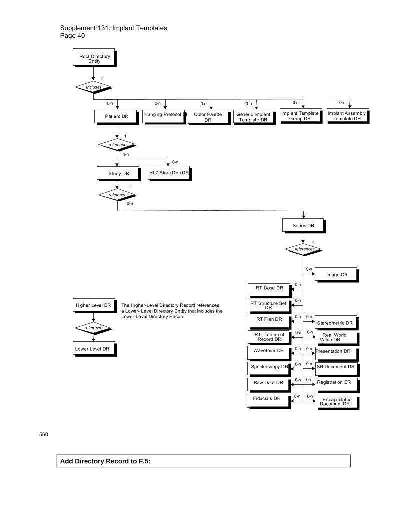
Supplement 131: Implant Templates Page 40
Patient DR
Study DR
references
Image DR
RT Dose DR
0-n
1
1
1-n
Root DirectoryEntity
includes 1
0-n
RT Structure SetDR
RT Plan DR
RT TreatmentRecord DR
Series DR
references 1
0-n
0-n
0-n
0-n
0-n
references
Higher Level DR
Lower Level DR
references
The Higher-Level Directory Record references a Lower- Level Directory Entity that includes the Lower-Level Directory Record
Presentation DR0-n Waveform DR 0-n
SR Document DR0-n 0-n
Fiducials DR 0-n
Spectroscopy DR
Registration DR0-n 0-nRaw Data DR
Hanging Protocol DR
0-n
0-n
HL7 Struc Doc DR
0-n Encapsulated
Document DR
0-n Real World
Value DR
0-n Stereometric DR
Color Palette DR
0-n
Generic Implant Template DR
0-n
Implant Template Group DR
0-n Implant Assembly
Template DR
0-n
560
Add Directory Record to F.5:

Supplement 131: Implant Templates Page 41
F.5.X Implant directory record definition The Directory Record is based on the specification of Section F.3. It is identified by a Directory Record Type of Value "IMPLANT". Table F.5-x lists the set of keys with their associated Types for 565 such a Directory Record Type. The description of these keys may be found in the Generic Implant Template IOD. This Directory Record shall be used to reference a Generic Implant Template SOP Instance.
Table F.5-x IMPLANT KEYS 570
Key Tag Type Attribute Description Manufacturer (0008,0070) 1 Name of the manufacturer that
produces the implant. Implant Name (0022,1095) 1 The (product) name of the implant. Implant Size (0068,6210) 1C The size descriptor of the
component. Required if present in the referenced instance.
Implant Part Number (0022,1097) 1 The (product) identifier of the implant.
Note: Because (0004,1511) Referenced SOP Instance UID in File may be used as a "pseudo"
Directory Record Key (See Table F.3-3), it is not duplicated in this list of keys.
F.5.Y Implant Assembly directory record definition 575
The Directory Record is based on the specification of Section F.3. It is identified by a Directory Record Type of Value „IMPLANT ASSY". Table F.5-y lists the set of keys with their associated Types for such a Directory Record Type. The description of these keys may be found in the Implant Assembly Template IOD. This Directory Record shall be used to reference an Implant Assembly Template SOP Instance. 580
Table F.5-y IMPLANT ASSEMBLY KEYS
Key Tag Type Attribute Description Implant Assembly Template Name
(0076,0001) 1 A name given to the assembly described in this instance.
Implant Assembly Template Issuer
(0076,0003) 1 The person or organization who issued the assembly template.
Procedure Type Code Sequence
(0076,0020) 1 A code describing the Intervention in which the implant is used. One or more Items shall be present in the Sequence.
>Include ‘Code Sequence Macro’ Table 8.8-1 Note: Because (0004,1511) Referenced SOP Instance UID in File may be used as a "pseudo"
Directory Record Key (See Table F.3-3), it is not duplicated in this list of keys. 585
F.5.Z Implant Group directory record definition The Directory Record is based on the specification of Section F.3. It is identified by a Directory Record Type of Value "IMPLANT GROUP". Table F.5-z lists the set of keys with their associated Types for such a Directory Record Type. The description of these keys may be found in the 590

Supplement 131: Implant Templates Page 42
Implant Template Group IOD. This Directory Record shall be used to reference an Implant Template Group SOP Instance.
Table F.5-Z IMPLANT GROUP KEYS
Key Tag Type Attribute Description Implant Template Group Name
(0078,0001) 1 Name of this group
Implant Template Group Description
(0078,0010) 3 Purpose or intent of this group.
Implant Template Group Issuer
(0078,0020) 1 Person or Organization which issued this group.
595
Note: Because (0004,1511) Referenced SOP Instance UID in File may be used as a "pseudo" Directory Record Key (See Table F.3-3), it is not duplicated in this list of keys.

Supplement 131: Implant Templates Page 43
600
605
Changes to NEMA Standards Publication PS 3.4-2009
Digital Imaging and Communications in Medicine (DICOM)
Part 4: Service Class Specifications 610

Supplement 131: Implant Templates Page 44
Item: Add the following to Table B.5-1
B.5 STANDARD SOP CLASSES
Table B.5-1 STANDARD SOP CLASSES 615
SOP Class Name SOP Class UID IOD Specification (defined in PS 3.3)
… Generic Implant Template Storage
1.2.840.10008.5.1.4.43.1 Generic Implant Template
Implant Assembly Template Storage
1.2.840.10008.5.1.4.44.1 Implant Assembly Template
Implant Template Group Storage
1.2.840.10008.5.1.4.45.1 Implant Template Group
…
Item: Add the following to PS 3.4 Section B.5.1
B.5.1.x Implant Template Storage SOP Classes A device that is a Generic Implant Template Storage, Implant Assembly Template Storage, or 620 Implant Template Group Storage SOP Class SCU may modify information in a SOP Instance that it has previously sent or received. When this SOP Instance is modified and sent to an SCP, it shall be assigned a new SOP Instance UID if there is addition, removal or update of any attribute within:
- Generic Implant Template Description Module 625
- Generic Implant Template 2D Drawings Module
- Generic Implant Template 3D Models Module
- Generic Implant Template Mating Features Module
- Generic Implant Template Planning Landmarks Module
- Implant Assembly Template Module 630
- Implant Template Group Module
- Surface Mesh Module
Referential integrity between sets of related SOP instances shall be maintained.
Item: Add the following to Table I.4-1 635

Supplement 131: Implant Templates Page 45
I.4 MEDIA STORAGE STANDARD SOP CLASSES
Table I.4-1 Media Storage Standard SOP Classes
SOP Class Name SOP Class UID IOD Specification … Generic Implant Template Storage
1.2.840.10008.5.1.4.43.1 Generic Implant Template
Implant Assembly Template Storage
1.2.840.10008.5.1.4.44.1 Implant Assembly Template
Implant Template Group Storage
1.2.840.10008.5.1.4.45.1 Implant Template Group
…
640

Supplement 131: Implant Templates Page 46
Item: Add the following Annex
Annex Y IMPLANT TEMPLATE QUERY/RETRIEVE SERVICE CLASSES
Y.1 OVERVIEW
Y.1.1 Scope The Implant Template Query/Retrieve Service Classes define application-level classes-of-service 645 that facilitate access to Implant Template and Implant Assembly Template composite objects.
Y.1.2 Conventions Key Attributes serve two purposes; they may be used as Matching Key Attributes or as Return Key Attributes. Matching Key Attributes may be used for matching (criteria to be used in the C-FIND request to determine whether an entity matches the query). Return Key Attributes may be 650 used to specify desired return attributes (what elements in addition to the Matching Key Attributes have to be returned in the C-FIND response).
Note: Matching Keys are typically used in an SQL ‘where’ clause. Return Keys are typically used in an SQL ‘select’ clause to convey the Attribute values.
655
Matching Key Attributes may be of Type "required" (R) or "optional" (O). Return Key Attributes may be of Type 1, 1C, 2, 2C, 3 as defined in PS 3.5.
Y.1.3 Query/Retrieve Information Model In order to serve as an SCP of the Implant Template Query/Retrieve Service Class, a DICOM AE 660 possesses information about the Attributes of a number of Implant Template or Implant Assembly Template composite SOP Instances. The information is organized into an Information Model. The Information Models for the different SOP Classes specified in this Annex are defined in Y.6.
Y.1.4 Service Definition Two peer DICOM AEs implement a SOP Class of an Implant Template or Implant Assembly 665 Template Query/Retrieve Service Class with one serving in the SCU role and one serving in the SCP role. SOP Classes of the Implant Template and Implant Assembly Template Query/Retrieve Service Classes are implemented using the DIMSE-C C-FIND, C-MOVE and C-GET services as defined in PS 3.7.
An SCP of this SOP Class shall support Level-2 conformance as defined in Section B.4.1. 670
The semantics of the C-FIND service are the same as those defined in the Service Definition of the Basic Worklist Management Service Class.
The semantics of the C-MOVE service are the same as those defined in the Service Definition of the Query/Retrieve Service Class, with the exception that there is only one level of retrieval.
The semantics of the C-GET service are the same as those defined in the Service Definition of 675 the Query/Retrieve Service Class, with the exception that there is only one level of retrieval.

Supplement 131: Implant Templates Page 47
Y.2 IMPLANT TEMPLATE INFORMATION MODELS DEFINITIONS
The Implant Template, Implant Assembly Template, and Implant Template Group Information Models are identified by the SOP Class negotiated at Association establishment time. Each SOP Class is composed of both an Information Model and a DIMSE-C Service Group. 680
The Implant Template, Implant Assembly Template, and Implant Template Group Information Models are defined in Y.6, with the Entity-Relationship Model Definition and Key Attributes Definition analogous to those defined in the Worklist Information Model Definition of the Basic Worklist Management Service.
Y.3 IMPLANT TEMPLATE INFORMATION MODELS 685
The Implant Template Information Models are based upon a one level entity:
— Implant Template object instance.
The Implant Template object instance contains Attributes associated with the Implant Template object IE of the Composite IODs as defined in PS 3.3.
The Implant Assembly Template Information Model is based upon a one level entity: 690
— Implant Assembly Template object instance.
The Implant Assembly Template object instance contains Attributes associated with the Implant Assembly Template object IE of the Composite IODs as defined in PS 3.3.
The Implant Assembly Group Information Model is based upon a one level entity:
— Implant Template Group object instance. 695
The Implant Template Group object instance contains Attributes associated with the Implant Template Group object IE of the Composite IODs as defined in PS 3.3.
Y.4 DIMSE-C SERVICE GROUPS
Y.4.1 C-FIND Operation See the C-FIND Operation definition for the Basic Worklist Management Service Class (K.4.1), 700 and substitute “Implant Template” for “Worklist”. The “Worklist” Search Method shall be used.
The SOP Class UID identifies the Implant Template or Implant Assembly Template, respectively Information Model against which the C-FIND is to be performed. The Key Attributes and values allowable for the query are defined in the SOP Class definitions for the Implant Template and Implant Assembly Template Information Model. 705
Y.4.1.1 Service Class User Behavior When receiving several Implant Template Instances with the same Implant Part Number, the receiving application shall use Effective DateTime (0068,6226) to determine the appropriate Instance.
Y.4.1.2 Service Class Provider Behavior 710
An SCP of this SOP Class shall support Level-2 conformance as defined in Section B.4.1.
Y.4.2 C-MOVE Operation See the C-MOVE Operation definition for the Query/Retrieve Service Class (C.4.2). No Extended Behavior or Relational-Retrieve is defined for the Implant Template and Implant Assembly Template Query/Retrieve Service Classes. 715

Supplement 131: Implant Templates Page 48
Query/Retrieve Level (0008,0052) is not relevant to the Implant Template and Implant Assembly Template Query/Retrieve Service Classes, and therefore shall not be present in the Identifier. The only Unique Key Attribute of the Identifier shall be SOP Instance UID (0008,0018). The SCU shall supply one UID or a list of UIDs.
Note: More than one entity may be retrieved, using List of UID matching. 720
Y.4.3 C-GET Operation See the C-GET Operation definition for the Query/Retrieve Service Class (C.4.2). No Extended Behavior or Relational-Retrieve is defined for the Implant Template and Implant Assembly Template Query/Retrieve Service Classes. 725
Note: More than one entity may be retrieved, using List of UID matching.
Y.5 ASSOCIATION NEGOTIATION
See the Association Negotiation definition for the Basic Worklist Management Service Class (K.5). 730
Y.6 SOP CLASS DEFINITIONS
Y.6.1 Implant Template Information Model Y.6.1.1 E/R Models The Implant Template Information Model consists of a single entity. In response to a given C-FIND request, the SCP shall send one C-FIND response per matching Implant Template 735 Instance.
Implant Template
Figure Y.6-1 IMPLANT TEMPLATE INFORMATION MODEL E/R DIAGRAM
The Implant Assembly Template Information Model consists of a single entity. In response to a 740 given C-FIND request, the SCP shall send one C-FIND response per matching Implant Assembly Template Instance.
Implant AssemblyTemplate
Figure Y.6-2 IMPLANT ASSEMBLY TEMPLATE INFORMATION MODEL E/R DIAGRAM 745
The Implant Template Group Information Model consists of a single entity. In response to a given C-FIND request, the SCP shall send one C-FIND response per matching Implant Template Group Instance.
Implant TemplateGroup
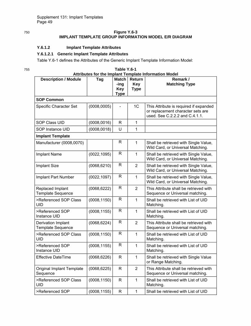
Supplement 131: Implant Templates Page 49
Figure Y.6-3 750 IMPLANT TEMPLATE GROUP INFORMATION MODEL E/R DIAGRAM
Y.6.1.2 Implant Template Attributes Y.6.1.2.1 Generic Implant Template Attributes Table Y.6-1 defines the Attributes of the Generic Implant Template Information Model:
Table Y.6-1 755 Attributes for the Implant Template Information Model
Description / Module Tag Match-ing Key Type
Return Key Type
Remark / Matching Type
SOP Common Specific Character Set (0008,0005) - 1C This Attribute is required if expanded
or replacement character sets are used. See C.2.2.2 and C.4.1.1.
SOP Class UID (0008,0016) R 1 SOP Instance UID (0008,0018) U 1 Implant Template Manufacturer (0008,0070) R 1 Shall be retrieved with Single Value,
Wild Card, or Universal Matching. Implant Name (0022,1095) R 1 Shall be retrieved with Single Value,
Wild Card, or Universal Matching. Implant Size (0068,6210) R 2 Shall be retrieved with Single Value,
Wild Card, or Universal Matching. Implant Part Number (0022,1097) R 1 Shall be retrieved with Single Value,
Wild Card, or Universal Matching. Replaced Implant Template Sequence
(0068,6222) R 2 This Attribute shall be retrieved with Sequence or Universal matching.
>Referenced SOP Class UID
(0008,1150) R 1 Shall be retrieved with List of UID Matching.
>Referenced SOP Instance UID
(0008,1155) R 1 Shall be retrieved with List of UID Matching.
Derivation Implant Template Sequence
(0068,6224) R 2 This Attribute shall be retrieved with Sequence or Universal matching.
>Referenced SOP Class UID
(0008,1150) R 1 Shall be retrieved with List of UID Matching.
>Referenced SOP Instance UID
(0008,1155) R 1 Shall be retrieved with List of UID Matching.
Effective DateTime (0068,6226) R 1 Shall be retrieved with Single Value or Range Matching.
Original Implant Template Sequence
(0068,6225) R 2 This Attribute shall be retrieved with Sequence or Universal matching.
>Referenced SOP Class UID
(0008,1150) R 1 Shall be retrieved with List of UID Matching.
>Referenced SOP (0008,1155) R 1 Shall be retrieved with List of UID

Supplement 131: Implant Templates Page 50
Description / Module Tag Match-ing Key Type
Return Key Type
Remark / Matching Type
Instance UID Matching. Implant Target Anatomy Sequence
(0068,6230) R 2 This Attribute shall be retrieved with Sequence or Universal matching.
>Anatomic Region Sequence
(0008,2218) R 1 This Attribute shall be retrieved with Single Value or Universal matching.
>>Code Value (0008,0100) R 1 This Attribute shall be retrieved with Single Value or Universal matching.
>>Coding Scheme Designator
(0008,0102) R 1 This Attribute shall be retrieved with Single Value or Universal matching.
>>Code Meaning (0008,0104) - 1 Implant Regulatory Disapproval Code Sequence
(0068,62A0) R 2 This Attribute shall be retrieved with Sequence or Universal matching.
>Code Value (0008,0100) R 1 This Attribute shall be retrieved with Single Value or Universal matching.
>Coding Scheme Designator
(0008,0102) R 1 This Attribute shall be retrieved with Single Value or Universal matching.
>Code Meaning (0008,0104) - 1
Material Code Sequence (0068,63A0) R 1 This Attribute shall be retrieved with Sequence or Universal matching.
>Code Value (0008,0100) R 1 This Attribute shall be retrieved with Single Value or Universal matching.
>Coding Scheme Designator
(0008,0102) R 1 This Attribute shall be retrieved with Single Value or Universal matching.
>Code Meaning (0008,0104) - 1 Coating Materials Code Sequence
(0068,63A4) R 1 This Attribute shall be retrieved with Sequence or Universal matching.
>Code Value (0008,0100) R 1 This Attribute shall be retrieved with Single Value or Universal matching.
>Coding Scheme Designator
(0008,0102) R 1 This Attribute shall be retrieved with Single Value or Universal matching.
>Code Meaning (0008,0104) - 1
Y.6.1.2.2 Implant Assembly Template Attributes Table Y.6-2 defines the Attributes of the Implant Assembly Template Information Model:
Table Y.6-2 760 Attributes for the Implant Assembly Template Information Model
Description / Module Tag Match-ing Key
Type
Return Key Type
Remark / Matching Type
SOP Common

Supplement 131: Implant Templates Page 51
Description / Module Tag Match-ing Key
Type
Return Key Type
Remark / Matching Type
Specific Character Set (0008,0005) - 1C This Attribute is required if expanded or replacement character sets are used. See C.2.2.2 and C.4.1.1.
SOP Class UID (0008,0016) R 1 SOP Instance UID (0008,0018) U 1 Implant Assembly Template
Implant Assembly Template Name
R 1 Shall be retrieved with Single Value, Wild Card, or Universal Matching.
Implant Assembly Template Issuer
(0076,0003) R 1 Shall be retrieved with Single Value, Wild Card, or Universal Matching.
Procedure Type Code Sequence
(0076,0020) R 1 This Attribute shall be retrieved with Single Value or Universal matching.
>Code Value (0008,0100) R 1 This Attribute shall be retrieved with Single Value or Universal matching.
>Coding Scheme Designator
(0008,0102) R 1 This Attribute shall be retrieved with Single Value or Universal matching.
>Code Meaning (0008,0104) - 1 Replaced Implant Assembly Template Sequence
(0076,0008) R 1 Shall be retrieved with Sequence or Universal Matching.
>Referenced SOP Class UID
(0008,1150) R 1 Shall be retrieved with List of UID Matching.
>Referenced SOP Instance UID
(0008,1155) R 1 Shall be retrieved with List of UID Matching.
Original Implant Assembly Template Sequence
(0076,000C) R 1 Shall be retrieved with Sequence or Universal Matching.
>Referenced SOP Class UID
(0008,1150) R 1 Shall be retrieved with List of UID Matching.
>Referenced SOP Instance UID
(0008,1155) R 1 Shall be retrieved with List of UID Matching.
Derivation Implant Assembly Template Sequence
(0076,000E) R 1 Shall be retrieved with Sequence or Universal Matching.
>Referenced SOP Class UID
(0008,1150) R 1 Shall be retrieved with List of UID Matching.
>Referenced SOP Instance UID
(0008,1155) R 1 Shall be retrieved with List of UID Matching.
Surgical Technique (0076,0030) R 2 Shall be retrieved with Single Value, Wild Card, or Universal Matching.
Y.6.1.2.3 Implant Template Group Attributes Table Y.6-3 defines the Attributes of the Implant Template Group Information Model:

Supplement 131: Implant Templates Page 52
Table Y.6-3 765 Attributes for the Implant Template Group Information Model
Description / Module Tag Match-ing Key
Type
Return Key Type
Remark / Matching Type
SOP Common Specific Character Set (0008,0005) - 1C This Attribute is required if expanded
or replacement character sets are used. See C.2.2.2 and C.4.1.1.
SOP Class UID (0008,0016) R 1 SOP Instance UID (0008,0018) U 1 Implant Template Group Implant Template Group Name
(0078,0001) R 1 Shall be retrieved with Single Value, Wild Card, or Universal Matching.
Implant Template Group Description
(0078,0010) - 2
Implant Template Group Issuer
(0078,0020) R 1 Shall be retrieved with Single Value, Wild Card, or Universal Matching.
Effective DateTime (0068,6226) R 1 Shall be retrieved with Single Value or Range Matching.
Replaced Implant Template Group Sequence
(0078,0026) R 2 Shall be retrieved with Sequence or Universal Matching
>Referenced SOP Class UID
(0008,1150) R 1 Shall be retrieved with List of UID Matching.
>Referenced SOP Instance UID
(0008,1155) R 1 Shall be retrieved with List of UID Matching.
Y.6.1.3 Conformance Requirements An implementation may conform to one of the Implant Template, Implant Assembly Template, or Implant Template Group Information Model SOP Classes as an SCU, SCP, any combination of 770 two of these, or all three. The Conformance Statement shall be in the format defined in PS 3.2.
Y.6.1.3.1 SCU Conformance Y.6.1.3.1.1 C-FIND SCU Conformance An implementation that conforms to one of the Implant Template, Implant Assembly Template, or Implant Template Group Information Model SOP Classes shall support queries against the 775 appropriate Information Model using the C-FIND SCU Behavior described for the Basic Worklist Management Service Class (see K.4.1.2 and Y.4.1).
An implementation that conforms to one of the Implant Template, Implant Assembly Template, or Implant Template Group Information Model SOP Classes as an SCU shall state in its Conformance Statement whether it requests Type 3 Return Key Attributes, and shall list these 780 Optional Return Key Attributes.
An implementation that conforms to one of the Implant Template, Implant Assembly Template, or Implant Template Group Information Model SOP Classes as an SCU shall state in its Conformance Statement how it makes use of Specific Character Set (0008,0005) when encoding queries and interpreting responses. 785
Supplement 131: Implant Templates Page 53
Y.6.1.3.1.2 C-MOVE SCU Conformance An implementation that conforms to one of the Implant Template, Implant Assembly Template, or Implant Template Group Information Model SOP Classes as an SCU shall support transfers against the appropriate Information Model, using the C-MOVE SCU baseline behavior described for the Query/Retrieve Service Class (see C.4.2.2.1 and Y.4.2). 790
Y.6.1.3.1.3 C-GET SCU Conformance An implementation that conforms to one of the Implant Template, Implant Assembly Template, or Implant Template Group Information Model SOP Classes as an SCU shall support transfers against the appropriate Information Model, using the C-GET SCU baseline behavior described for the Query/Retrieve Service Class (see C.4.3.2). 795
Y.6.1.3.2 SCP Conformance Y.6.1.3.2.1 C-FIND SCP Conformance An implementation that conforms to one of the Implant Template, Implant Assembly Template, or Implant Template Group Information Model SOP Classes as an SCP shall support queries against the appropriate Template Information Model, using the C-FIND SCP Behavior described 800 for the Basic Worklist Management Service Class (see K.4.1.3).
An implementation that conforms to one of the Implant Template, Implant Assembly Template, or Implant Template Group Information Model SOP Classes as an SCP shall state in its Conformance Statement whether it supports Type 3 Return Key Attributes, and shall list these Optional Return Key Attributes. 805
An implementation that conforms to one of the Implant Template, Implant Assembly Template, or Implant Template Group Information Model SOP Classes as an SCP shall state in its Conformance Statement how it makes use of Specific Character Set (0008,0005) when interpreting queries, performing matching and encoding responses.
Y.6.1.3.2.2 C-MOVE SCP Conformance 810
An implementation that conforms to one of the Implant Template, Implant Assembly Template, or Implant Template Group Information Model SOP Classes as an SCP shall support transfers against the appropriate Information Model, using the C-MOVE SCP baseline behavior described for the Query/Retrieve Service Class (see C.4.2.3.1).
An implementation that conforms to one of the Implant Template, Implant Assembly Template, or 815 Implant Template Group Information Model SOP Classes as an SCP, which generates transfers using the C-MOVE operation, shall state in its Conformance Statement appropriate Storage Service Class, under which it shall support the C-STORE sub-operations generated by the C-MOVE.
Y.6.1.3.2.3 C-GET SCP Conformance 820
An implementation which conforms to one of the SOP Classes of the Implant Template, Implant Assembly Template, or Implant Template Group Information Model SOP Class Group as an SCP shall support retrievals against the Query/Retrieve Information Model described in Section C.6.1.1 using the C-GET SCP Behavior described in Section C.4.3.3. 825 Y.6.1.4 SOP Classes The SOP Classes of the Implant Template Information Models in the Implant Template Query/Retrieve Service Class identify the Implant Template Information Models, and the DIMSE-C operations supported. The SOP Classes of the Implant Assembly Template Information Models in the Implant Assembly Template Query/Retrieve Service Class identify the Implant Assembly 830 Template Information Models, and the DIMSE-C operations supported. The SOP Classes of the Implant Template Group Information Models in the Implant Template Group Query/Retrieve

Supplement 131: Implant Templates Page 54
Service Class identify the Implant Template Group Information Models, and the DIMSE-C operations supported. The following Standard SOP Classes are identified:
SOP Class Name SOP Class UID Generic Implant Template Information Model – FIND
1.2.840.10008.5.1.4.43.2
Generic Implant Template Information Model - MOVE
1.2.840.10008.5.1.4.43.3
Generic Implant Template Information Model – GET
1.2.840.10008.5.1.4.43.4
Implant Assembly Template Information Model – FIND
1.2.840.10008.5.1.4.44.2
Implant Assembly Template Information Model - MOVE
1.2.840.10008.5.1.4.44.3
Implant Assembly Template Information Model – GET
1.2.840.10008.5.1.4.44.4
Implant Template Group Information Model – FIND
1.2.840.10008.5.1.4.45.2
Implant Template Group Information Model - MOVE
1.2.840.10008.5.1.4.45.3
Implant Template Group Information Model – GET
1.2.840.10008.5.1.4.45.4
835

Supplement 131: Implant Templates Page 55
840
Changes to NEMA Standards Publication PS 3.6-2009 845
Digital Imaging and Communications in Medicine (DICOM)
Part 6: Data Dictionary

Supplement 131: Implant Templates Page 56
Item: Add or the following Data Elements to Part 6 Section 6:
6 Registry of DICOM data elements 850
Tag Name Keyword VR VM (0068,6210) Implant Size ImplantSize LO 1 (0068,6221) Implant Template Version ImplantTemplateVersion LO 1 (0068,6222) Replaced Implant Template Sequence ReplacedImplantTemplateSequence SQ 1 (0068,6223) Implant Type ImplantType CS 1 (0068,6224) Derivation Implant Template Sequence DerivationImplantTemplateSequenc
e SQ 1
(0068,6225) Original Implant Template Sequence OriginalImplantTemplateSequence SQ 1 (0068,6226) Effective DateTime EffectiveDateTime DT 1 (0068,6230) Implant Target Anatomy Sequence ImplantTargetAnatomySequence SQ 1 (0068,6260) Information From Manufacturer
Sequence InformationFromManufacturerSequence SQ 1
(0068,6265) Notification From Manufacturer Sequence
NotificationFromManufacturerSequence SQ 1
(0068,6270) Information Issue DateTime InformationIssueDateTime DT 1 (0068,6280) Information Summary InformationSummary ST 1 (0068,62A0) Implant Regulatory Disapproval Code
Sequence ImplantRegulatoryDisapprovalCodeSequence SQ 1
(0068,62A5) Overall Template Spatial Tolerance OverallTemplateSpatialTolerance FD 1 (0068,62C0) HPGL Document Sequence HPGLDocumentSequence SQ 1 (0068,62D0) HPGL Document ID HPGLDocumentID US 1 (0068,62D5) HPGL Document Label HPGLDocumentLabel LO 1 (0068,62E0) View Orientation Code Sequence ViewOrientationCodeSequence SQ 1 (0068,62F0) View Orientation Modifier ViewOrientationModifier FD 9 (0068,62F2) HPGL Document Scaling HPGLDocumentScaling FD 1 (0068,6300) HPGL Document HPGLDocument OB 1 (0068,6310) HPGL Contour Pen Number HPGLContourPenNumber US 1 (0068,6320) HPGL Pen Sequence HPGLPenSequence SQ 1 (0068,6330) HPGL Pen Number HPGLPenNumber US 1 (0068,6340) HPGL Pen Label HPGLPenLabel LO 1 (0068,6345) HPGL Pen Description HPGLPenDescription ST 1 (0068,6346) Recommended Rotation Point RecommendedRotationPoint FD 2 (0068,6347) Bounding Rectangle BoundingRectangle FD 4 (0068,6350) Implant Template 3D Model Surface
Number ImplantTemplate3DModelSurfaceNumber US 1-n
(0068,6360) Surface Model Description Sequence SurfaceModelDescriptionSequence SQ 1
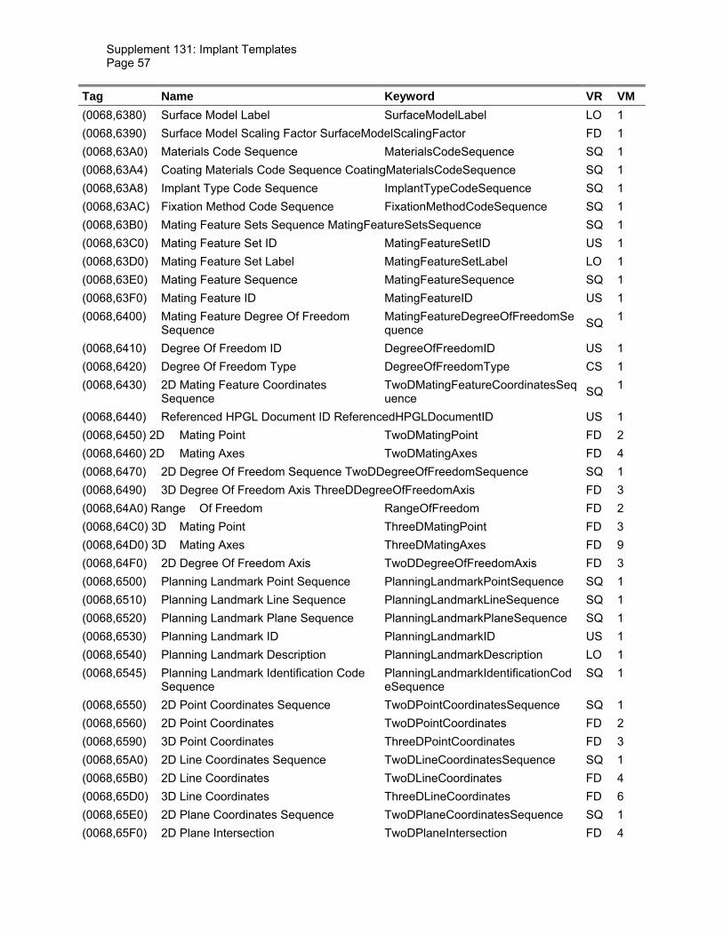
Supplement 131: Implant Templates Page 57
Tag Name Keyword VR VM (0068,6380) Surface Model Label SurfaceModelLabel LO 1 (0068,6390) Surface Model Scaling Factor SurfaceModelScalingFactor FD 1 (0068,63A0) Materials Code Sequence MaterialsCodeSequence SQ 1 (0068,63A4) Coating Materials Code Sequence CoatingMaterialsCodeSequence SQ 1 (0068,63A8) Implant Type Code Sequence ImplantTypeCodeSequence SQ 1 (0068,63AC) Fixation Method Code Sequence FixationMethodCodeSequence SQ 1 (0068,63B0) Mating Feature Sets Sequence MatingFeatureSetsSequence SQ 1 (0068,63C0) Mating Feature Set ID MatingFeatureSetID US 1 (0068,63D0) Mating Feature Set Label MatingFeatureSetLabel LO 1 (0068,63E0) Mating Feature Sequence MatingFeatureSequence SQ 1 (0068,63F0) Mating Feature ID MatingFeatureID US 1 (0068,6400) Mating Feature Degree Of Freedom
Sequence MatingFeatureDegreeOfFreedomSequence SQ 1
(0068,6410) Degree Of Freedom ID DegreeOfFreedomID US 1 (0068,6420) Degree Of Freedom Type DegreeOfFreedomType CS 1 (0068,6430) 2D Mating Feature Coordinates
Sequence TwoDMatingFeatureCoordinatesSequence SQ 1
(0068,6440) Referenced HPGL Document ID ReferencedHPGLDocumentID US 1 (0068,6450) 2D Mating Point TwoDMatingPoint FD 2 (0068,6460) 2D Mating Axes TwoDMatingAxes FD 4 (0068,6470) 2D Degree Of Freedom Sequence TwoDDegreeOfFreedomSequence SQ 1 (0068,6490) 3D Degree Of Freedom Axis ThreeDDegreeOfFreedomAxis FD 3 (0068,64A0) Range Of Freedom RangeOfFreedom FD 2 (0068,64C0) 3D Mating Point ThreeDMatingPoint FD 3 (0068,64D0) 3D Mating Axes ThreeDMatingAxes FD 9 (0068,64F0) 2D Degree Of Freedom Axis TwoDDegreeOfFreedomAxis FD 3 (0068,6500) Planning Landmark Point Sequence PlanningLandmarkPointSequence SQ 1 (0068,6510) Planning Landmark Line Sequence PlanningLandmarkLineSequence SQ 1 (0068,6520) Planning Landmark Plane Sequence PlanningLandmarkPlaneSequence SQ 1 (0068,6530) Planning Landmark ID PlanningLandmarkID US 1 (0068,6540) Planning Landmark Description PlanningLandmarkDescription LO 1 (0068,6545) Planning Landmark Identification Code
Sequence PlanningLandmarkIdentificationCodeSequence
SQ 1
(0068,6550) 2D Point Coordinates Sequence TwoDPointCoordinatesSequence SQ 1 (0068,6560) 2D Point Coordinates TwoDPointCoordinates FD 2 (0068,6590) 3D Point Coordinates ThreeDPointCoordinates FD 3 (0068,65A0) 2D Line Coordinates Sequence TwoDLineCoordinatesSequence SQ 1 (0068,65B0) 2D Line Coordinates TwoDLineCoordinates FD 4 (0068,65D0) 3D Line Coordinates ThreeDLineCoordinates FD 6 (0068,65E0) 2D Plane Coordinates Sequence TwoDPlaneCoordinatesSequence SQ 1 (0068,65F0) 2D Plane Intersection TwoDPlaneIntersection FD 4

Supplement 131: Implant Templates Page 58
(0068,6610) 3D Plane Origin ThreeDPlaneOrigin FD 3 (0068,6620) 3D Plane Normal ThreeDPlaneNormal FD 3 (0076,0001) Implant Assembly Template Name ImplantAssemblyTemplateName LO 1 (0076,0003) Implant Assembly Template Issuer ImplantAssemblyTemplateIssuer LO 1 (0076,0006) Implant Assembly Template Version ImplantAssemblyTemplateVersion LO 1 (0076,0008) Replaced Implant Assembly Template
Sequence ReplacedImplantAssemblyTemplateSequence
SQ 1
(0076,000A) Implant Assembly Template Type ImplantAssemblyTemplateType CS 1 (0076,000C) Original Implant Assembly Template
Sequence OriginalImplantAssemblyTemplateSequence
SQ 1
(0076,000E) Derivation Implant Assembly Template Sequence
DerivationImplantAssemblyTemplateSequence
SQ 1
(0076,0010) Implant Assembly Template Target Anatomy Sequence
ImplantAssemblyTemplateTargetAnatomySequence
SQ 1
(0076,0020) Procedure Type Code Sequence ProcedureTypeCodeSequence SQ 1 (0076,0030) Surgical Technique SurgicalTechnique LO 1 (0076,0032) Component Types Sequence ComponentTypesSequence SQ 1 (0076,0034) Component Type Code Sequence ComponentTypeCodeSequence CS 1 (0076,0036) Exclusive Component Type ExclusiveComponentType CS 1 (0076,0038) Mandatory Component Type MandatoryComponentType CS 1 (0076,0040) Component Sequence ComponentSequence SQ 1 (0076,0055) Component ID ComponentID US 1 (0076,0060) Component Assembly Sequence ComponentAssemblySequence SQ 1 (0076,0070) Component 1 Referenced ID Component1ReferencedID US 1 (0076,0080) Component 1 Referenced Mating
Feature Set ID Component1ReferencedMatingFeatureSetID
US 1
(0076,0090) Component 1 Referenced Mating Feature ID
Component1ReferencedMatingFeatureID
US 1
(0076,00A0) Component 2 Referenced ID Component2ReferencedID US 1 (0076,00B0) Component 2 Referenced Mating
Feature Set ID Component2ReferencedMatingFeatureSetID
US 1
(0076,00C0) Component 2 Referenced Mating Feature ID
Component2ReferencedMatingFeatureID
US 1
(0078,0001) Implant Template Group Name ImplantTemplateGroupName LO 1 (0078,0010) Implant Template Group Description ImplantTemplateGroupDescription ST 1 (0078,0020) Implant Template Group Issuer ImplantTemplateGroupIssuer LO 1 (0078,0024) Implant Template Group Version ImplantTemplateGroupVersion LO 1 (0078,0026) Replaced Implant Template Group
Sequence ReplacedImplantTemplateGroupSequence
SQ 1
(0078,0028) Implant Template Group Target Anatomy Sequence
ImplantTemplateGroupTargetAnatomySequence
SQ 1
(0078,002A) Implant Template Group Members Sequence
ImplantTemplateGroupMembersSequence
SQ 1
(0078,002E) Implant Template Group Member ID ImplantTemplateGroupMemberID US 1
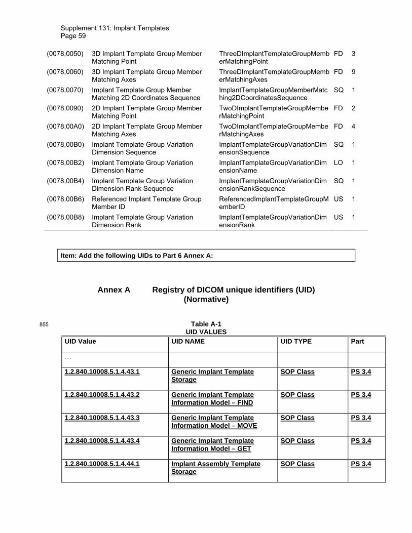
Supplement 131: Implant Templates Page 59
(0078,0050) 3D Implant Template Group Member Matching Point
ThreeDImplantTemplateGroupMemberMatchingPoint
FD 3
(0078,0060) 3D Implant Template Group Member Matching Axes
ThreeDImplantTemplateGroupMemberMatchingAxes
FD 9
(0078,0070) Implant Template Group Member Matching 2D Coordinates Sequence
ImplantTemplateGroupMemberMatching2DCoordinatesSequence
SQ 1
(0078,0090) 2D Implant Template Group Member Matching Point
TwoDImplantTemplateGroupMemberMatchingPoint
FD 2
(0078,00A0) 2D Implant Template Group Member Matching Axes
TwoDImplantTemplateGroupMemberMatchingAxes
FD 4
(0078,00B0) Implant Template Group Variation Dimension Sequence
ImplantTemplateGroupVariationDimensionSequence
SQ 1
(0078,00B2) Implant Template Group Variation Dimension Name
ImplantTemplateGroupVariationDimensionName
LO 1
(0078,00B4) Implant Template Group Variation Dimension Rank Sequence
ImplantTemplateGroupVariationDimensionRankSequence
SQ 1
(0078,00B6) Referenced Implant Template Group Member ID
ReferencedImplantTemplateGroupMemberID
US 1
(0078,00B8) Implant Template Group Variation Dimension Rank
ImplantTemplateGroupVariationDimensionRank
US 1
Item: Add the following UIDs to Part 6 Annex A:
Annex A Registry of DICOM unique identifiers (UID) (Normative)
Table A-1 855 UID VALUES
UID Value UID NAME UID TYPE Part
…
1.2.840.10008.5.1.4.43.1 Generic Implant Template Storage
SOP Class PS 3.4
1.2.840.10008.5.1.4.43.2 Generic Implant Template Information Model – FIND
SOP Class PS 3.4
1.2.840.10008.5.1.4.43.3 Generic Implant Template Information Model – MOVE
SOP Class PS 3.4
1.2.840.10008.5.1.4.43.4 Generic Implant Template Information Model – GET
SOP Class PS 3.4
1.2.840.10008.5.1.4.44.1 Implant Assembly Template Storage
SOP Class PS 3.4

Supplement 131: Implant Templates Page 60
1.2.840.10008.5.1.4.44.2 Implant Assembly Template Information Model – FIND
SOP Class PS 3.4
1.2.840.10008.5.1.4.44.3 Implant Assembly Template Information Model – MOVE
SOP Class PS 3.4
1.2.840.10008.5.1.4.44.4 Implant Assembly Template Information Model – GET
SOP Class PS 3.4
1.2.840.10008.5.1.4.45.1 Implant Template Group Storage
SOP Class PS 3.4
1.2.840.10008.5.1.4.45.2 Implant Template Group Information Model – FIND
SOP Class PS 3.4
1.2.840.10008.5.1.4.45.3 Implant Template Group Information Model – MOVE
SOP Class PS 3.4
1.2.840.10008.5.1.4.45.4 Implant Template Group Information Model – GET
SOP Class PS 3.4
…

Supplement 131: Implant Templates Page 61
860
865
Changes to NEMA Standards Publication PS 3.15-2009
Digital Imaging and Communications in Medicine (DICOM)
Part 15: Security and Systems Management Profiles
870
Supplement 131: Implant Templates Page 62
Item: Add to Section C2 and C3
C.2 CREATOR RSA DIGITAL SIGNATURE PROFILE
…
xx. any Attributes of the Implant Template module that are present 875
yy. any Attributes of the Implant Assembly Template module that are present zz. any Attributes of the Implant Template Group module that are present
C.3 AUTHORIZATION RSA DIGITAL SIGNATURE PROFILE
… 880
xx. any Attributes of the Implant Template module that are present yy. any Attributes of the Implant Assembly Template module that are present zz. any Attributes of the Implant Template Group module that are present
885

Supplement 131: Implant Templates Page 63
890
Changes to NEMA Standards Publication PS 3.16-2009
Digital Imaging and Communications in Medicine (DICOM) 895
Part 16: Content Mapping Resource
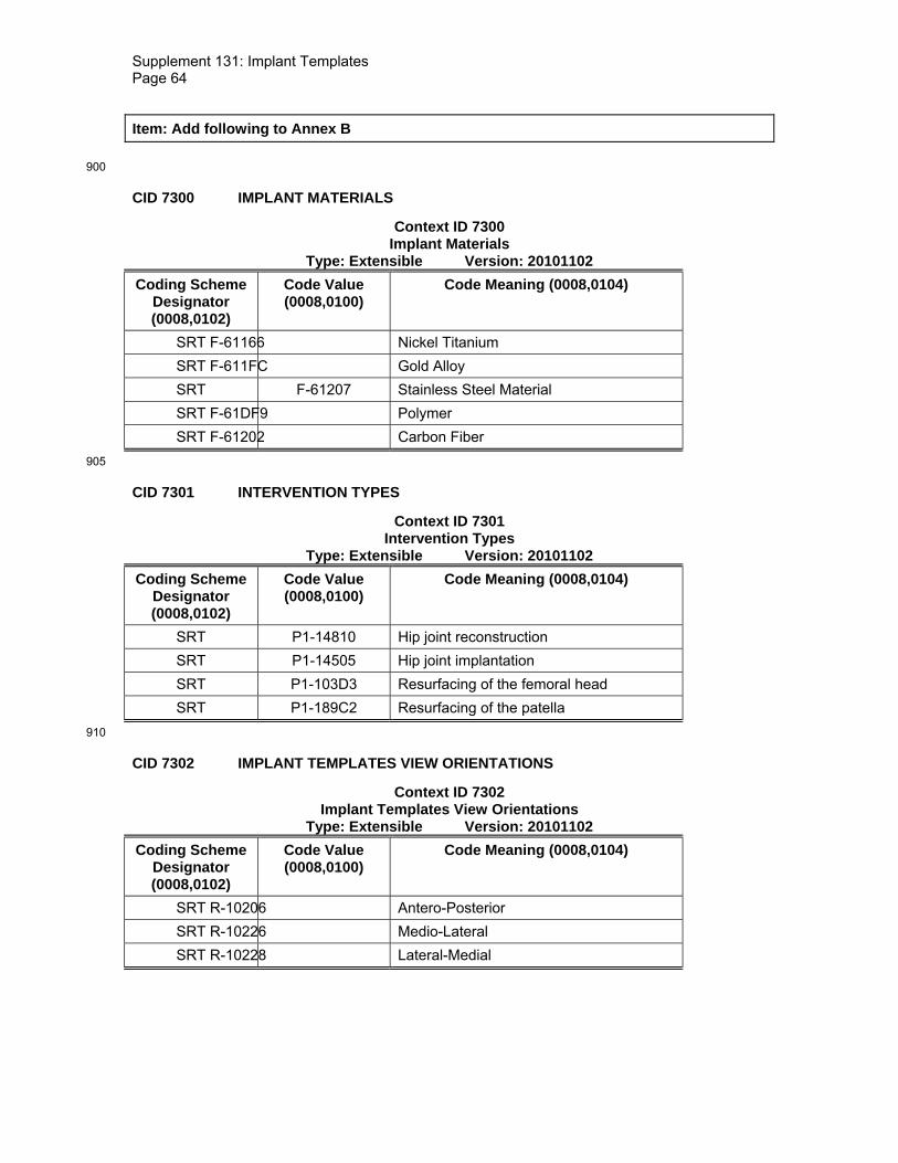
Supplement 131: Implant Templates Page 64
Item: Add following to Annex B
900
CID 7300 IMPLANT MATERIALS
Context ID 7300 Implant Materials
Type: Extensible Version: 20101102 Coding Scheme
Designator (0008,0102)
Code Value (0008,0100)
Code Meaning (0008,0104)
SRT F-61166 Nickel Titanium SRT F-611FC Gold Alloy SRT F-61207 Stainless Steel Material SRT F-61DF9 Polymer SRT F-61202 Carbon Fiber
905
CID 7301 INTERVENTION TYPES
Context ID 7301 Intervention Types
Type: Extensible Version: 20101102 Coding Scheme
Designator (0008,0102)
Code Value (0008,0100)
Code Meaning (0008,0104)
SRT P1-14810 Hip joint reconstruction SRT P1-14505 Hip joint implantation SRT P1-103D3 Resurfacing of the femoral head SRT P1-189C2 Resurfacing of the patella
910
CID 7302 IMPLANT TEMPLATES VIEW ORIENTATIONS
Context ID 7302 Implant Templates View Orientations
Type: Extensible Version: 20101102 Coding Scheme
Designator (0008,0102)
Code Value (0008,0100)
Code Meaning (0008,0104)
SRT R-10206 Antero-Posterior SRT R-10226 Medio-Lateral SRT R-10228 Lateral-Medial

Supplement 131: Implant Templates Page 65
915
CID 7303 IMPLANT TEMPLATES MODIFIED VIEW ORIENTATIONS
Context ID 7303 Implant Templates Modified View Orientations
Type: Extensible Version: 20101102 Coding Scheme
Designator (0008,0102)
Code Value (0008,0100)
Code Meaning (0008,0104)
DCM 112300 AP+45 DCM 112301 AP-45
920
CID 7304 IMPLANT TARGET ANATOMY
Context ID 7304 Implant Target Anatomy
Type: Extensible Version: 20101102 Coding Scheme
Designator (0008,0102)
Code Value (0008,0100)
Code Meaning (0008,0104)
SRT T-15750 Ankle Joint SRT T-11501 Cervical Spine SRT T-D00F7 Cervico-Thoracic Spine SRT T-D8300 Elbow SRT T-11196 Facial Bones SRT T-12710 Femur SRT T-12711 Head of Femur SRT T-D078C Proximal Femur SRT T-12717 Shaft of Femur SRT T-D078D Distal Femur SRT T-1553D Finger Joint SRT T-15710 Hip Joint SRT T-D1213 Jaw Region SRT T-D9200 Knee SRT T-11503 Lumbar Spine SRT T-D0059 Lumbo-Sacral Spine SRT T-11180 Mandible SRT T-11170 Maxilla SRT T-12730 Patella SRT T-12310 Clavicle SRT T-D2220 Shoulder SRT T-12410 Humerus SRT T-1240F Proximal Humerus

Supplement 131: Implant Templates Page 66
SRT T-12412 Shaft of Humerus SRT T-1241F Distal Humerus SRT T-12420 Radius SRT T-1242A Proximal Radius SRT T-12423 Shaft of Radius SRT T-1242B Distal Radius SRT T-12430 Ulna SRT T-1243A Proximal Ulna SRT T-12435 Shaft of Ulna SRT T-1243B Distal Ulna SRT T-11100 Skull SRT T-12600 Hand SRT T-11502 Thoracic Spine SRT T-D00FA Thoraco-Lumbar Spine SRT T-15460 Wrist Joint SRT T-12375 Pelvis SRT T-12750 Fibula SRT T-12780 Talus SRT T-12770 Calcaneus SRT T-12740 Tibia SRT T-12746 Shaft of Tibia SRT T-1274B Distal Tibia
925
CID 7305 IMPLANT PLANNING LANDMARKS
Context ID 7305 Implant Planning Landmarks
Type: Extensible Version: 20101102 Coding Scheme
Designator (0008,0102)
Code Value (0008,0100)
Code Meaning (0008,0104
Include CID 7306 Human Hip Implant Planning Landmarks 930
CID 7306 HUMAN HIP IMPLANT PLANNING LANDMARKS
Context ID 7306 Human Hip Implant Planning Landmarks Type: Extensible Version: 20101102
Coding Scheme Designator (0008,0102)
Code Value (0008,0100)
Code Meaning (0008,0104)
DCM 112302 Anatomical axis of femur

Supplement 131: Implant Templates Page 67
DCM 112303 Acetabular Center of Rotation DCM 112304 Femur Head Center of Rotation
935
CID 7307 IMPLANT COMPONENT TYPES
Context ID 7307 Implant Component Types
Type: Extensible Version: 20101102 Coding Scheme
Designator (0008,0102)
Code Value (0008,0100)
Code Meaning (0008,0104)
Include CID 7308 Human Hip Implant Component Types Include CID 7309 Human Trauma Implant Component Types
940
CID 7308 HUMAN HIP IMPLANT TYPES
Context ID 7308 Human Hip Implant Component Types
Type: Extensible Version: 20101102 Coding Scheme
Designator (0008,0102)
Code Value (0008,0100)
Code Meaning (0008,0104)
DCM 112305 Acetabular Cup Shell DCM 112306 Acetabular Cup Insert DCM 112307 Acetabular Cup Monoblock SRT A-04459 Femoral Head Prosthesis DCM 112308 Femoral Head Ball Component DCM 112309 Femoral Head Cone Taper Component DCM 112310 Femoral Stem DCM 112311 Femoral Stem Distal Component DCM 112312 Femoral Stem Proximal Component DCM 112313 Femoral Stem Component DCM 112314 Neck Component DCM 112315 Monoblock Stem DCM 112315 Distal Centralizer DCM 112316 Prosthetic Shaft Augment DCM 112317 Femoral Head Resurfacing Component
945
CID 7309 HUMAN TRAUMA IMPLANT TYPES
Context ID 7309 Human Trauma Implant Component Types Type: Extensible Version: 20101102

Supplement 131: Implant Templates Page 68
Coding Scheme Designator (0008,0102)
Code Value (0008,0100)
Code Meaning (0008,0104)
SRT A-12030 Screw SRT A-12010 Bone Plate SRT A-12018 DHS Plate SRT A-12020 Bone Nail
950
CID 7310 IMPLANT FIXATION METHOD
Context ID 7310 Implant Fixation Method
Type: Extensible Version: 20101102 Coding Scheme
Designator (0008,0102)
Code Value (0008,0100)
Code Meaning (0008,0104)
SRT P0-02126 Anchoring SRT P0-02125 Fusion SRT P0-021D6 Gluing SRT P1-1099B Internal fixation using internal fixator system SRT P1-10999 Internal fixation using plate SRT P1-10998 Internal fixation using screw SRT P1-10997 Internal fixation using staple SRT R-41C37 Cemented component fixation SRT R-42808 Uncemented component fixation SRT P1-08080 Repair by nailing DCM 112318 Pinning DCM 112319 Sewing DCM 112320 Bolting DCM 112321 Wedging
955
Item: Add the following entries to the table in Annex D.
DICOM Code Definitions
Code Value
Code Meaning Definition Notes
112305 Acetabular Cup Shell Prosthetic component implanted into the acetabulum. Provides hold for the insert that is mounted inside the cup.

Supplement 131: Implant Templates Page 69
112306 Acetabular Cup Insert Prosthetic pelvic joint component. Inserted into the cup, takes in the femoral head replacement.
112307 Acetabular Cup Monoblock
Prosthetic pelvic joint cup including insert.
A-04459 Femoral Head Prosthesis
Prosthetic component that replaces the original femoral head. Mounted on the neck of a femoral stem replacement or partial replacement.
112308 Femoral Head Ball Component
Component for Femoral Head Prosthesis where the conic intake for the stem neck can be exchanged. Combined with a Femoral Head Cone Taper Component.
112309 Femoral Head Cone Taper Component
Exchangeable neck intake for composite femoral head prosthesis.

Supplement 131: Implant Templates Page 70
Combined with a Femoral Head Ball Component.
112310 Femoral Stem Prosthesis Implanted into the femoral bone to provide force transmission between joint replacement and bone. On the proximal end a conic neck holds the femoral head replacement.
112311 Femoral Stem Distal Component
Distal half of a modular stem prosthesis system. Combined with a Stem Proximal Component.
112312 Femoral Stem Proximal Component
Proximal half of a modular stem prosthesis system. Combined with a Stem Distal Component.

Supplement 131: Implant Templates Page 71
112313 Femoral Stem Component
Stem prosthetic component with a modular insert for an exchangeable neck component. Combined with a Neck Component.
112314 Neck Component Prosthetic Neck to be combined with a Stem Component.
112315 Monoblock Stem Prosthetic Stem and Femoral Head in one piece.
112315 Distal Centralizer Attachment to the distal end of a cemented stem assuring that the stem is in a central position inside the drilled femoral canal before cementation.

Supplement 131: Implant Templates Page 72
112316 Prosthetic Shaft Augment
A proximal attachment to the shaft used to compensate for bone deficiencies or bone loss.
112317 Femoral Head Resurfacing Component
Artificial femur head surface needed for the partial replacement of the femoral head where only the surface is replaced.
P1-103D3 Resurfacing of the femoral head
Partial replacement of the femoral head where only the surface is replaced.
112300 AP+45 View Orientation Modifier indicates that the view orientation of the imaging plane is rotated +45° along the cranial-caudal axis
112301 AP-45 View Orientation Modifier indicates that the view orientation of the imaging plane is rotated -45° along the cranial-caudal axis.
112318 Pinning Fixation using a pin 112319 Sewing Fixation sewing several objects
together
112320 Bolting Fixation using a bolt 112321 Wedging Fixation due to forcing an object
into a narrow space
112302 Anatomical axis of femur
The axis following the shaft of the femur
112303 Acetabular Center of Rotation
Center of Rotation of the natural Acetabulum

Supplement 131: Implant Templates Page 73
112304 Femur Head Center of Rotation
Center of Rotation of the natural femur head

Supplement 131: Implant Templates Page 74
960
965
Changes to NEMA Standards Publication PS 3.17-2009
Digital Imaging and Communications in Medicine (DICOM)
Part 17: Explanatory Information 970

Supplement 131: Implant Templates Page 75
Item: Add following Section to PS 3.17
X Implant Template Description
X.1 IMPLANT MATING 975
In this section, the usage of mating features for assembly of implants is declared.
X.1.1 Mating Features These Attributes establish a Cartesian coordinate system relative to the Frame of Reference of the implant. When two implants are assembled using a pair of mating features, a rigid spatial registration can be established, that transforms one Frame of Reference so that the mating 980 features align. The figure below gives a simple example in 2D how two implants (symbolized by two rectangles) are matched according to a mating feature pair. For each 2D and 3D template present, a set of coordinates is assigned to each Mating Feature Sequence Item.
Figure X.1-1 IMPLANT TEMPLATE MATING (EXAMPLE). 985
X.1.2 Mating Feature ID It is recommended to give Mating Features that are somehow related, the same Mating Feature ID (0068,63F0) in different implant templates. This may help applications to switch between components while keeping connections to other components. The Example in Figure X.1-2 shows that the first and the last hole in the plates get the same Mating Feature ID in each 990 Template.
1
2
1
2

Supplement 131: Implant Templates Page 76
Figure X.1-2 IMPLANT TEMPLATE MATING FEATURE IDS (EXAMPLE).
X.1.3 Mating Feature Sets 995
The Mating Features are organized in sets of alternative features: Only one feature of any set shall be used for assembly with other components in one plan. This enables the definition of variants for one kind of contact a component can make while ensuring consistent plans.
An example for Mating Feature Sets is shown in Figure X.1-2. A hip stem template shows a set of five mating features, drawn as circles on the tip of its cone. Different head components use 1000 different mating points, depending on the base radius of the conic intake on the head.
HPGL Document ID View Orientation
1 MEDIAL-LAT ERAL
2 ANTERIOR-POSTERIOR
Mating Feature ID: 1
2D Mating Feature Coordinates Sequence
Referenced HPGL Document ID
2D Mating Point
2D Mating Axes
1 6.87 / 44.91 1 / 0 / 0 / 1
2 44.24 / 16.7 0.6947 / 0.7193 / -0.7193 / 0.6947
Mating Feature ID: 2
2D Mating Feature Coordinates Sequence
Referenced HPGL Document ID
2D Mating Point
2D Mating Axes
1 6.87 / 44.23 1 / 0 / 0 / 1
2 43.58 / 16 0.6947 / 0.7193 / -0.7193 / 0.6947

Supplement 131: Implant Templates Page 77
Figure X.1-2 2D MATING FEATURE COORDINATES SEQUENCE (EXAMPLE).
X.1.4 Degrees of Freedom 1005
For each Item of the Mating Feature Sequence (0068,63E0), degrees of freedom can be specified. A degree of freedom is defined by one axis, and can be either rotational or translational. For each 2D and 3D template present, the geometric specifications of the mating points can be provided.
X.1.5 Implant Assembly Templates 1010
Instances of the Implant Assembly Template IOD are utilized to define intended combinations of implant templates. An Implant Assembly Template consists of a sequence of component type definitions (Component Type Sequence (0076,0032)) which references Implant Template Instances and assigns roles to the referenced implants. In the example in Figure X.1-3, the component types “Stems” and “Heads” are defined. Four different stems and two different heads 1015 are referenced. Both groups are flagged mandatory and exclusive, i.e. a valid assembly requires exactly one representative of each group.
The Component Assembly Sequence (0076,0060) declares possible connections between components referenced by the component groups. Each sequence item refers to exactly two implant templates which are part of at least one component group in the same Implant Assembly 1020 Template Instance. An Component Assembly Sequence Item references one mating feature in each of the templates according to which the assembly is geometrically constrained. The double-pointed dashed lines represent the Items of the Component Assembly Sequence in Figure X.1-3.
Component Group 1 „Stems“ (Mandatory, Exclusive)
1 2 3 4
5 6
Component Group 2 „Heads“ (Mandatory, Exclusive)

Supplement 131: Implant Templates Page 78
Figure X.1-3 1025 IMPLANT ASSEMBLY TEMPLATE (EXAMPLE).
X.2 PLANNING LANDMARKS
Registration of implant templates with patient images according to anatomical landmarks is one of the major features of implantation planning. For that purpose, geometric features can be 1030 attached to Implant Template Instances. Three kinds of landmarks are defined: Points, lines, and planes. Each landmark consists of its geometric definition which is defined per template and a description.
When registering an Implant Template to a patient dataset like an Image or a Surface Segmentation, the planning software should establish a spatial transformation that matches to 1035 planning landmarks to corresponding geometric features in the patient dataset.
X.3 IMPLANT REGISTRATION AND MATING EXAMPLE
In this section, an example is presented that shows the usage of Implant Templates together with an Implant Assembly Template to create an Implantation Plan with patient images. The example is in 2D but can easily be extended to 3D as well. The example looks at a simplified case of hip 1040 reconstruction planning, using a monoblock stem component and a monoblock cup component. Planning consists of 2 steps: Selection and placement of the best fitting cup from the cups referenced by the Assembly Template based on the dimension of the patient’s hip is the first step. With that done, a stem is selected that can be mated with the selected cup and has a neck configuration that leads to an optimal outcome with regard to leg length and other parameters. 1045 Therefore, the available stems are placed so that the features align. The femoral planning landmarks are used to calculate the displacement of the femur this configuration would result in. The workflow is shown in the following set of figures.

Supplement 131: Implant Templates Page 79
Figure X.3-1 1050 IMPLANT TEMPLATES USED IN THE EXAMPLE.
In the first step, the planning landmarks marked with the green arrows in Figure X.3-2 are aligned with compliant positions in the patient’s x-ray.
Figure X.3-2 1055 CUP IS ALIGNED WITH PATIENT’S ACETABULUM USING 2 LANDMARKS
In the second step, the femoral length axis is detected from the patient’s x-ray and the stem template is aligned accordingly using the femoral axis landmark. The proximal and distal fixation boundary planes are used to determine the insertion depth of the stem along that axis.
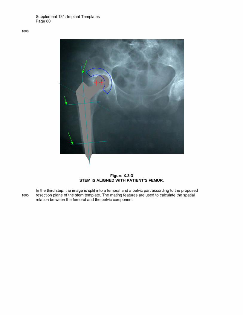
Supplement 131: Implant Templates Page 80
1060
Figure X.3-3 STEM IS ALIGNED WITH PATIENT’S FEMUR.
In the third step, the image is split into a femoral and a pelvic part according to the proposed resection plane of the stem template. The mating features are used to calculate the spatial 1065 relation between the femoral and the pelvic component.

Supplement 131: Implant Templates Page 81
Figure X.3-4 FEMORAL AND PELVIC SIDE ARE REGISTERED.
X.3.1 Degrees Of Freedom 1070
The hip joint has several degrees of freedom, of course. The Implant Template should contain this information in the Mating Features. In the given 2D projections, the rotational freedom of the joint is expressed by one single rotation around the axis of projection intersecting with the printing space at the 2D coordinate of the Mating Feature. Therefore, a Degree Of Freedom Sequence Item added to either the stem, the cup, or both. 1075
In planning, this information could be used to visualize the rotational capacities of the joint after implantation.
Note: Technically, the degree of freedom could also have been added to the cup or even (each with half the range of freedom) to both. But since we are used to see femurs rotation with respect to pelvises and not the other way around, it seemed natural to do it that way. 1080

Supplement 131: Implant Templates Page 82
Figure X.3-5 ROTATIONAL DEGREE OF FREEDOM
X.4 ENCODING EXAMPLE
The Templates used in the example can be encoded as follows: 1085
Table X.4-1 Attributes Used to Describe a Mono Stem Implant for Total Hip Replacement
Attribute Value Comment SOP Common Module SOP Class UID 1.2.840.10008.5.1.4.43.1 SOP Instance UID 1.2.3.4.5.6.7.0.1 Generic Implant Template Module Manufacturer ACME Implant Name MONO_STEM Implant Size MEDIUM Implant Part Number ACME_MST_M Effective DateTime 26.06.2009 12:00 Implant Template Version 1 Implant Template Type ORIGINAL Implant Target Anatomy Sequence >Anatomic Region Sequence >>Code Value T-12710 >>Coding Scheme Designator SRT >>Code Meaning Femur Frame of Reference UID 1.2.3.4.5.6.7.1.1 Overall Template Spatial Tolerance 1.0 HPGL Document Sequence >HPGL Document ID 1
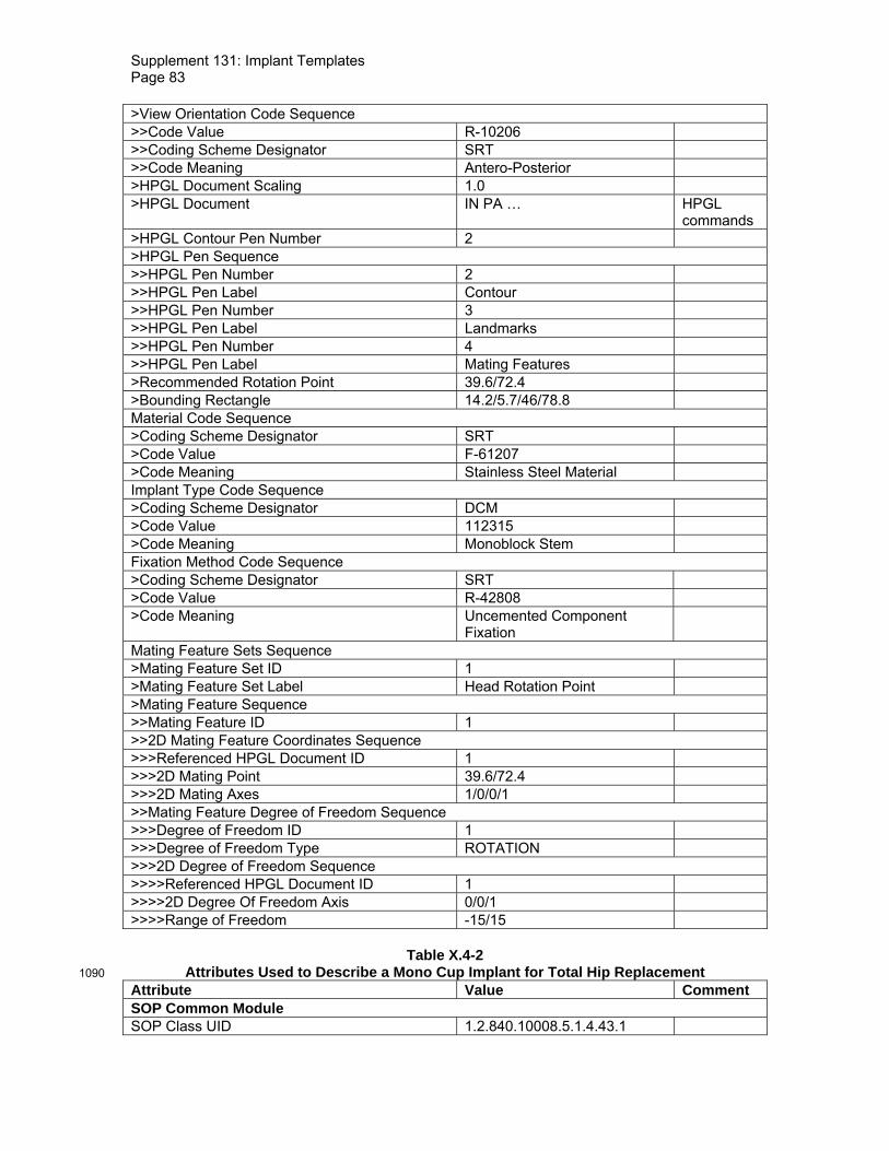
Supplement 131: Implant Templates Page 83
>View Orientation Code Sequence >>Code Value R-10206 >>Coding Scheme Designator SRT >>Code Meaning Antero-Posterior >HPGL Document Scaling 1.0 >HPGL Document IN PA … HPGL
commands >HPGL Contour Pen Number 2 >HPGL Pen Sequence >>HPGL Pen Number 2 >>HPGL Pen Label Contour >>HPGL Pen Number 3 >>HPGL Pen Label Landmarks >>HPGL Pen Number 4 >>HPGL Pen Label Mating Features >Recommended Rotation Point 39.6/72.4 >Bounding Rectangle 14.2/5.7/46/78.8 Material Code Sequence >Coding Scheme Designator SRT >Code Value F-61207 >Code Meaning Stainless Steel Material Implant Type Code Sequence >Coding Scheme Designator DCM >Code Value 112315 >Code Meaning Monoblock Stem Fixation Method Code Sequence >Coding Scheme Designator SRT >Code Value R-42808 >Code Meaning Uncemented Component
Fixation
Mating Feature Sets Sequence >Mating Feature Set ID 1 >Mating Feature Set Label Head Rotation Point >Mating Feature Sequence >>Mating Feature ID 1 >>2D Mating Feature Coordinates Sequence >>>Referenced HPGL Document ID 1 >>>2D Mating Point 39.6/72.4 >>>2D Mating Axes 1/0/0/1 >>Mating Feature Degree of Freedom Sequence >>>Degree of Freedom ID 1 >>>Degree of Freedom Type ROTATION >>>2D Degree of Freedom Sequence >>>>Referenced HPGL Document ID 1 >>>>2D Degree Of Freedom Axis 0/0/1 >>>>Range of Freedom -15/15
Table X.4-2
Attributes Used to Describe a Mono Cup Implant for Total Hip Replacement 1090 Attribute Value Comment SOP Common Module SOP Class UID 1.2.840.10008.5.1.4.43.1

Supplement 131: Implant Templates Page 84
SOP Instance UID 1.2.3.4.5.6.7.0.2 Generic Implant Template Module Manufacturer ACME Implant Name MONO_CUP Implant Size MEDIUM Implant Part Number ACME_MCP_M Effective DateTime 26.06.2009 12:00 Implant Template Version 1 Implant Template Type ORIGINAL Implant Target Anatomy Sequence >Anatomic Region Sequence >>Code Value T-15710 >>Coding Scheme Designator SRT >>Code Meaning Hip Joint Frame of Reference UID 1.2.3.4.5.6.7.1.2 Overall Template Spatial Tolerance 1.0 HPGL Document Sequence >HPGL Document ID 1 >View Orientation Code Sequence >>Code Value G-5215 >>Coding Scheme Designator SRT >>Code Meaning Anterior Projection >HPGL Document Scaling 1 >HPGL Document IN PA … HPGL
commands >HPGL Contour Pen Number 2 >HPGL Pen Sequence >>HPGL Pen Number 2 >>HPGL Pen Label Contour >>HPGL Pen Number 3 >>HPGL Pen Label Landmarks >>HPGL Pen Number 4 >>HPGL Pen Label Mating Features >Recommended Rotation Point 12.9/0 >Bounding Rectangle 0/0/25.8/12.9 Material Code Sequence >Coding Scheme Designator SRT >Code Value F-61207 >Code Meaning Stainless Steel Material Implant Type Code Sequence >Coding Scheme Designator DCM >Code Value 112307 >Code Meaning Acetabular Cup Monoblock Fixation Method Code Sequence >Coding Scheme Designator SRT >Code Value R-42808 >Code Meaning Uncemented Component
Fixation
Mating Feature Sets Sequence >Mating Feature Set ID 1 >Mating Feature Set Label Hip Joint Mating Feature >Mating Feature Sequence

Supplement 131: Implant Templates Page 85
>>Mating Feature ID 1 >>2D Mating Feature Coordinates Sequence >>>Referenced HPGL Document ID 1 >>>2D Mating Point 12.9/0 >>>2D Mating Axes 0.707/0.707/-0.707/0.707
Table X.4-3
Attributes Used to Describe the Assembly of Cup and Stem Attribute Value Comment SOP Common Module SOP Class UID 1.2.840.10008.5.1.4.44.1 SOP Instance UID 1.2.3.4.5.6.7.0.3 Implant Assembly Template Module Implant Assembly Template Name Acme Hip Assembly Implant Assembly Template Issuer ACME Effective DateTime 26.06.2009 12:00 Implant Assembly Template Version 1 Implant Assembly Template Type ORIGINAL Implant Assembly Template Target Anatomy Sequence >Anatomic Region Sequence >>Code Value T-15710 >>Coding Scheme Designator SRT >>Code Meaning Hip Joint Procedure Type Code Sequence >Code Value P1-14810 >Coding Scheme Designator SRT >Code Meaning Hip Joint Reconstruction Component Types Sequence >Component Type Code Sequence Sequence
Item 1 > Coding Scheme Designator DCM > Code Value 112310 > Code Meaning Femoral Stem >Exclusive Component Type YES >Mandatory Component Type YES >Component Sequence >>Referenced SOP Class UID 1.2.840.10008.5.1.4.43.1 >>Referenced SOP Instance UID 1.2.3.4.5.6.7.0.1 >>Component ID 1 >Component Type Code Sequence Sequence
Item 2 > Coding Scheme Designator DCM > Code Value 112305 > Code Meaning Acetabular Cup Shell >Exclusive Component Type YES >Mandatory Component Type YES >Component Sequence >>Referenced SOP Class UID 1.2.840.10008.5.1.4.43.1 >>Referenced SOP Instance UID 1.2.3.4.5.6.7.0.2 >>Component ID 2 Component Assembly Sequence

Supplement 131: Implant Templates Page 86
>Component 1 Referenced ID 1 The stem
>Component 1 Referenced Mating Feature Set ID
1
> Component 1 Referenced Mating Feature ID 1
>Component 2 Referenced ID 2 The cup
> Component 2 Referenced Mating Feature Set ID
1
> Component 2 Referenced Mating Feature ID 1 X.5 IMPLANT TEMPLATE VERSIONS AND DERIVATION 1095
The Generic Implant Module contains several Attributes to express the relations between different versions of implant templates. These Attributes are
(0022,1097)
Implant Part Number Number (or alphanumerical code) assigned by the manufacturer of an implant to one particular release of one particular part. Whenever changes on the implant design are made, a new implant part number is assigned.
(0068,6226)
Effective DateTime Date and time from which on an Implant Template Instance is valid.
(0068,6221)
Implant Template Version Number assigned by the creator of an ORIGINAL Implant Template Instance. When an implant manufacturer issues a new version of an implant template without doing changes on the implant itself, it issues a new instance with the same part number but a different template version.
(0068,6222)
Replaced Implant Template Sequence
When a manufacturer issues a new version of an Implant Template, the instance contains a reference to it direct predecessor.
(0068,6223)
Implant Type When a software vendor, user or other entity creates a “proprietary” version of an Implant Template by adding Attributes, the resulting Instance is labeled DERIVED.
(0068,6225)
Original Implant Template When an Instance is DERIVED, it contains a reference to the ORIGINAL instance it was derived from (directly or with several derived versions in between).
(0068,6224)
Derivation Implant Template Sequence
When an Implant Template Instance is derived from another instance, it contains a reference to the Implant Template Instance it was directly derived from.
Different versions of Implant Templates reflect the changes a manufacturer is doing on the Implant Templates he issues. The Implant Templates which are issued by a manufacturer (or a 1100 third party who is acting on behalf of the manufacturer) are always ORIGINAL. Software vendors, PACS integrators, or other stakeholders will add information to such templates for different purposes. The Instances which are generated by this process is called derivation and the

Supplement 131: Implant Templates Page 87
resulting instances are labeled DERIVED. Implantation Plans, i.e. electronic documents describing the result of implantation planning, are specified in an instance of the Implantation 1105 Plan SR Document. There, the implants which are relevant for one plan are included by reference. When such plans are exchanged between systems or organizations it is likely that the receiving party has access to other versions of templates as the sending party has. In order to maintain readability of exchanged plans, the following is required:
1. All necessary information about an implant which is relevant to display and understand a 1110 plan is present in the ORIGINAL Implant Templates which were issued by a manufacturer. This is assured by these Attributes being Type 1 in the IOD.
2. When deriving Instances, information may only be added but not removed from the ORIGINAL Instance. This information may be encoded in standard or private Tags.
3. Derived Instances contain the information about the source Instances they were derived 1115 from. All Instances contain a reference to the ORIGINAL Instance they were derived from. If an application receives a plan which references an implant it does not have in its database, it will find the UID of the ORIGINAL Instance in the plan, too. It can query its database for an instance which was derived from that Instance and thereby find an Instance it can use to present the plan. 1120
Figure X.5-1 shows an example of the relationships between two versions of a manufacturer’s Implant Template and several different Implant Templates derived by software vendors from these versions.

Supplement 131: Implant Templates Page 88
Figure X.5-1 1125 IMPLANT VERSIONS AND DERIVATION.
Real-World Implant
Part Number
Implant Template A
ORIGINAL Version 1
Implant Template A
Manufacturer
Replaced Implant Template
ORIGINAL Version 2
Implant Template A1
DERIVED Version 1
Derivation Implant Template
Original Implant Template
Implant Template A1
DERIVED Version 2
Derivation Implant Template
Original Implant Template
Implant Template A2
DERIVED Version 2
Derivation Implant Template
Original Implant Template
PACS System Integrator
Replaced Implant Template
issues
issues update
Software Vendor
issues
issues