Embed Size (px)
Citation preview
The contents of this literature are as of Jul. 2013This catalog is printed with soy ink.MGS-DG-1307-EN-C
http://www.magnescale.com
Shinagawa Intercity Tower A-18F, 2-15-1, Konan, Minato-ku, Tokyo 108-6018, JAPAN
Magnescale Co., Ltd.
HeadquartersTokyo OfficeNagoya OfficeOsaka OfficeInternational Sales DepartmentMagnescale Americas Inc. Magnescale Europe GmbH
45 Suzukawa, Isehara-shi, Kanagawa 259-1146, JAPANShinagawa Intercity Tower A-18F, 2-15-1, Konan, Minato-ku, Tokyo 108-6018, JAPAN2-35-16, Meieki, Nakamura-ku, Nagoya Aichi, 450-0002, JAPAN2-14-6, Nishi-Nakajima, Yodogawa-ku, Osaka 532-0011, JAPAN45 Suzukawa, Isehara-shi, Kanagawa 259-1146, JAPAN5740 Warland Drive, Cypress, CA 90630, USAAntoniusstrasse 14, 73249 Wernau, Germany
TEL.+81(0)463-92-1011TEL.+81(0)3-5460-3574TEL.+81(0)52-587-1823TEL.+81(0)6-6305-3101TEL.+81(0)463-92-7971TEL.+1(562)594-5060 TEL.+49(0) 7153 934 291
FAX.+81(0)463-92-1012FAX.+81(0)3-5460-9614FAX.+81(0)52-587-1848FAX.+81(0)6-6304-6586FAX.+81(0)463-92-7978FAX.+1(562)594-5061FAX.+49(0) 7153 934 299
:::::::
Digital Gauge General Catalog
Magnescale Co., Ltd.
E-mail : [email protected] : [email protected] : [email protected] : [email protected] : [email protected] : [email protected]
2 3
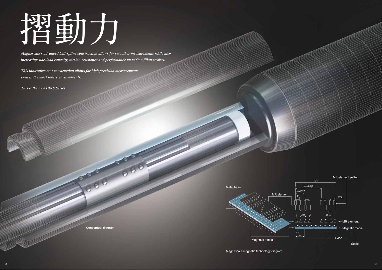
Conceptual diagram
摺動力Magnescale’s advanced ball-spline construction allows for smoother measurements while also
increasing side-load capacity, torsion resistance and performance up to 60 million strokes.
This innovative new construction allows for high precision measurements
even in the most severe environments.
This is the new DK-S Series.
Metal base
Magnetic media
MR element
1chMR element pattern
Magnescale magnetic technology diagram
Ch+ Ch-V G
(m+1/2)P
(n+1/2)P
P
6
12
34
57 8
MR element
Magnetic media
Base
P
1 2 3 4 5 6 7 8
λ
Scale
P/6

4 5
Features & Superiority
Adapts bearings of new construction superior in sliding force and durability. It has slim shape whose main body size is φ8 mm and is high-precision digital gauge suitable for automatic measurements.
Achieved number of strokes: 60 millionMaximum resolution: 0.1 µmResponse Speed: 250 m/min (at resolution of 0.5 µm) Adopt: High-fl ex cable (standard)Adopt: IP67 rating with bellows Linear encoder technology allows high precision measuring over the entire range.
Easy integration into machines with compact square body.
Compact size and high rigidity
It is suitable for general purpose and automatic measurements.
Multifunctional counters
Optional expansion boards available (LY71) BCD output(LY71)Comparator(Relay,open collector output) (LY71) RS232-C Output (LY72)
Multipoint measurementIntelligent Network Systems: MG40 series
Equipped with Ethernet interface as standard and supporting CC-Link
Unit: MG10/20/30 series
Equipped with RS-232C interface as standard
High rigidity Φ20mm body is suitable for harsh environments. Also, it enables high response speed in automatic measurements.
According to varied materials to be measured, measuring force can be selected. Available in lengths up to 205mm with 0.5µm resolution. Magnetic feeler tips equipped as standard make it easy to integrate into machines. (DK155/205) High-fl ex cable (standard): 250 m/min (at resolution of 0.5 µm) High-fl ex cable (standard) Linear encoder technology allows high precision measuring over the entire range.
DK800S Series
DK Series
Compact LT Series counters of DIN size
Current, maximum and minimum, and P-P value measuring function Comparator2-axis ADD/SUB functionBCD/RS-232C input/output Reference point function
6 7
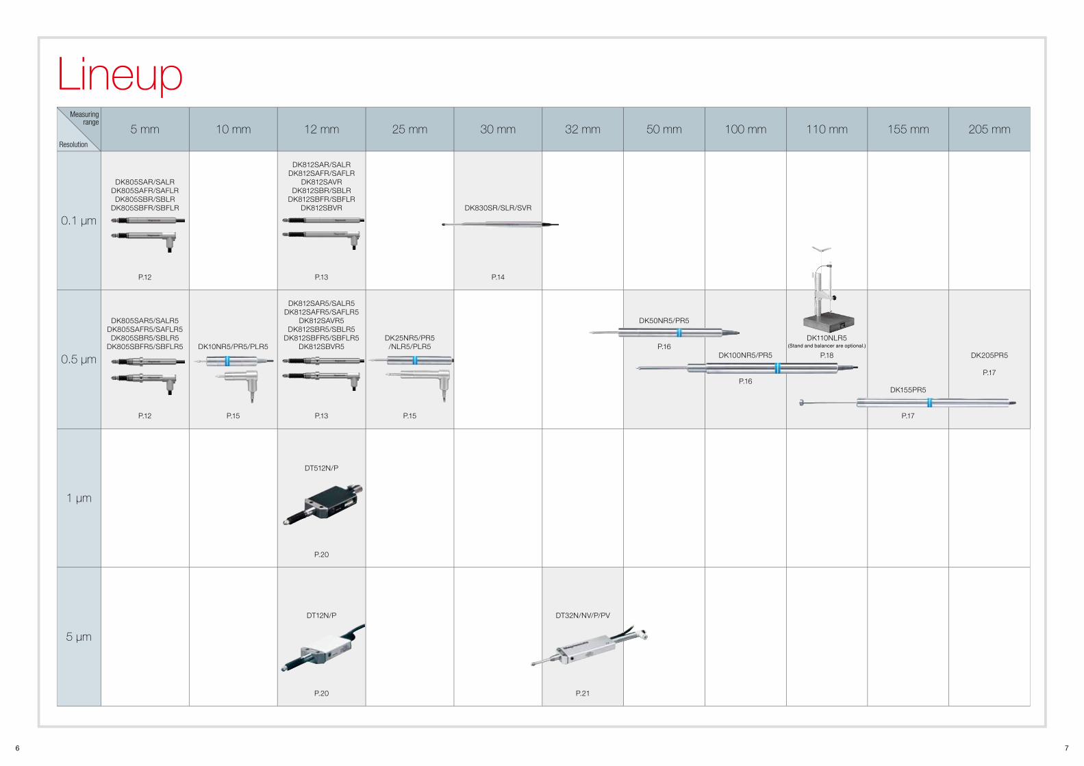
Lineup5 mm 10 mm 12 mm 25 mm 30 mm 32 mm 50 mm 100 mm 110 mm 155 mm 205 mm
0.1 µm
DK805SAR/SALRDK805SAFR/SAFLRDK805SBR/SBLR
DK805SBFR/SBFLR
P.12
DK812SAR/SALRDK812SAFR/SAFLR
DK812SAVRDK812SBR/SBLR
DK812SBFR/SBFLRDK812SBVR
P.13
DK830SR/SLR/SVR
P.14
0.5 µm
DK805SAR5/SALR5DK805SAFR5/SAFLR5DK805SBR5/SBLR5
DK805SBFR5/SBFLR5
P.12
DK10NR5/PR5/PLR5
P.15
DK812SAR5/SALR5DK812SAFR5/SAFLR5
DK812SAVR5DK812SBR5/SBLR5
DK812SBFR5/SBFLR5DK812SBVR5
P.13
DK25NR5/PR5/NLR5/PLR5
P.15
DK50NR5/PR5
P.16DK100NR5/PR5
P.16
DK110NLR5(Stand and balancer are optional.)
P.18
DK155PR5
P.17
DK205PR5
P.17
1 µm
DT512N/P
P.20
5 µm
DT12N/P
P.20
DT32N/NV/P/PV
P.21
Resolution
Measuring range
8 9
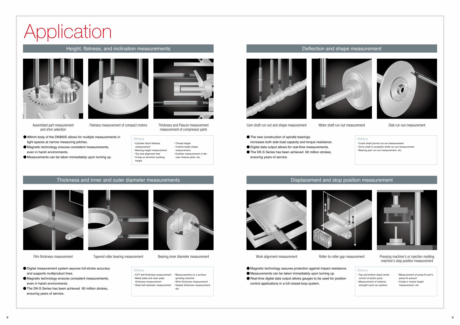
Application
Cylinder block flatness measurement Bearing height measurement Toe and alignment test Crimp-on terminal caulking height
Thread height Turbine blade shape measurement Camber measurement of die-cast chassis parts, etc.
Crank shaft journal run-out measurement Drive shaft or propeller shaft run-out measurement Bearing part run-out measurement, etc.
CVT belt thickness measurement Metal plate and resin plate thickness measurement Steel ball diameter measurement
Measurements on a surface grinding machine Shim thickness measurement Gasket thickness measurement, etc.
Top and bottom dead center control of piston parts Measurement of material strength (such as camber)
Measurement of press-fit part’s press-fit amount Coater’s nozzle height measurement, etc.
Height, fl atness, and inclination measurements Defl ection and shape measurement
Thickness and inner and outer diameter measurements Displacement and stop position measurement
Assembled part measurementand shim selection
Cam shaft run-out and shape measurement
Film thickness measurement Work alignment measurement
Flatness measurement of compact motors Motor shaft run-out measurement
Tapered roller bearing measurement Roller-to-roller gap measurement
Φ8mm body of the DK800S allows for multiple measurements in tight spaces at narrow measuring pitches. Magnetic technology ensures consistent measurements, even in harsh environments. Measurements can be taken immediately upon turning up.
The new construction of spindle bearings increases both side-load capacity and torque resistance. Digital data output allows for real-time measurements. The DK-S Series has been achieved 60 million strokes, ensuring years of service.
Digital measurement system assures full-stroke accuracy and supports multiproduct lines. Magnetic technology ensures consistent measurements, even in harsh environments. The DK-S Series has been achieved 60 million strokes, ensuring years of service.
Magnetic technology assures protection against impact resistance. Measurements can be taken immediately upon turning up. Real-time digital data output allows gauges to be used for position control applications in a full closed-loop system.
Thickness and Flexure measurement measurement of compressor parts
Disk run-out measurement
Bearing inner diameter measurement Pressing machine’s or injection molding machine’s stop position measurement
Others Others
Others Others
10 11
Gauges
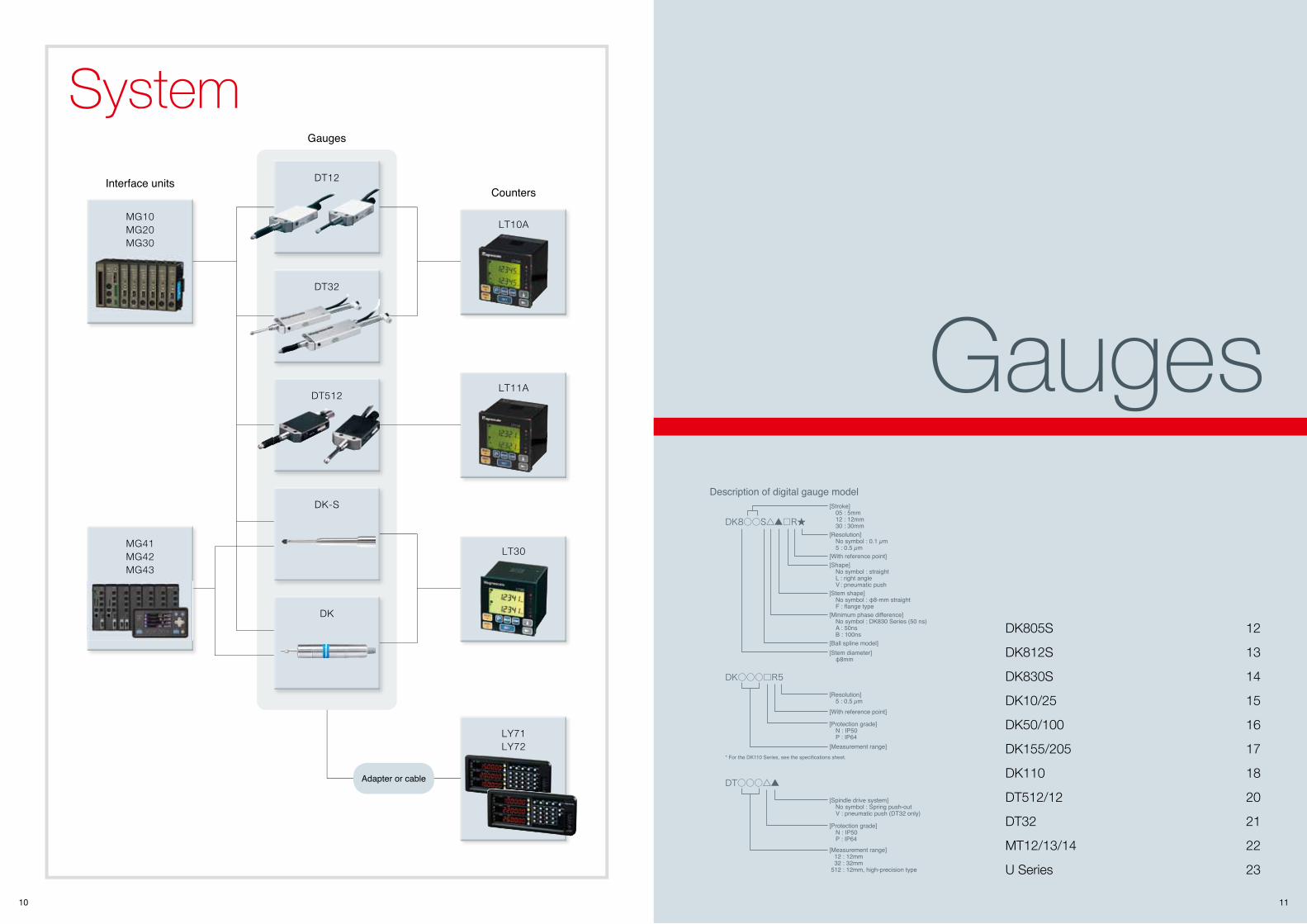
DK805S 12
DK812S 13
DK830S 14
DK10/25 15
DK50/100 16
DK155/205 17
DK110 18
DT512/12 20
DT32 21
MT12/13/14 22
U Series 23
System
Interface units
Gauges
CountersDT12
DT32
DT512
DK-S
DK
LY71LY72
LT10A
LT11A
LT30
MG10MG20MG30
MG41MG42MG43
Adapter or cable
[Ball spline model][Stem diameter] φ8mm
[Stroke] 05 : 5mm 12 : 12mm 30 : 30mm[Resolution] No symbol : 0.1 µm 5 : 0.5 µm
[Shape] No symbol : straight L : right angle V : pneumatic push[Stem shape] No symbol : φ8-mm straight F : flange type[Minimum phase difference] No symbol : DK830 Series (50 ns) A : 50ns B : 100ns
[With reference point]
[Resolution] 5 : 0.5 µm
[Measurement range]
[Protection grade] N : IP50 P : IP64
[With reference point]
[Spindle drive system] No symbol : Spring push-out V : pneumatic push (DT32 only)
[Measurement range] 12 : 12mm 32 : 32mm 512 : 12mm, high-precision type
[Protection grade] N : IP50 P : IP64
Description of digital gauge model
* For the DK110 Series, see the specifications sheet.
DK8○○S△▲□R★
DK○○○□R5
DT○○○△▲
12 13
DK DK DK812SDK805S
DT(MT)
UMG
LTLY
DKSDK
DT(MT)
UMG
LTLY
DKSDK
*1 Under specific test conditions defined by Magnescale Co., Ltd. *2 Excluding the interpolation box and connector *3 When φ4 mm tube is connected for right-angle model *4 Excluding cable section and interpolation box *1 Under specific test conditions defined by Magnescale Co., Ltd. Pueumatic push Model: 30 million time *2 Excluding the interpolation box and connector
*3 When φ4 mm tube is connected for right-angle model *4 Excluding cable section and interpolation box
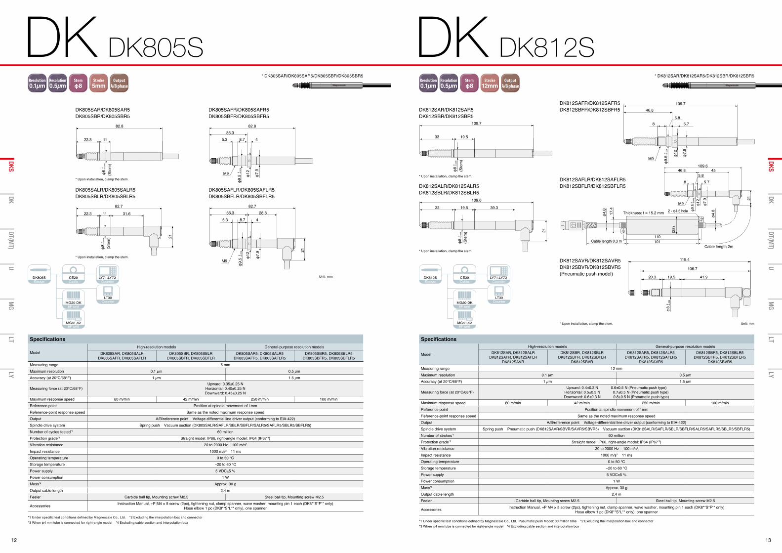
Specifications
ModelHigh-resolution models General-purpose resolution models
DK805SAR, DK805SALRDK805SAFR, DK805SAFLR
DK805SBR, DK805SBLRDK805SBFR, DK805SBFLR
DK805SAR5, DK805SALR5DK805SAFR5, DK805SAFLR5
DK805SBR5, DK805SBLR5DK805SBFR5, DK805SBFLR5
Measuring range 5 mmMaximum resolution 0.1 µm 0.5 µmAccuracy (at 20°C/68°F) 1 µm 1.5 µm
Measuring force (at 20°C/68°F)Upward: 0.35±0.25 N
Horizontal: 0.40±0.25 N Downward: 0.45±0.25 N
Maximum response speed 80 m/min 42 m/min 250 m/min 100 m/minReference point Position at spindle movement of 1mmReference-point response speed Same as the noted maximum response speedOutput A/B/reference point Voltage-differential line driver output (conforming to EIA-422) Spindle drive system Spring push Vacuum suction (DK805SALR/SAFLR/SBLR/SBFLR/SALR5/SAFLR5/SBLR5/SBFLR5)Number of cycles tested*1 60 millionProtection grade*2 Straight model: IP66, right-angle model: IP64 (IP67*3)Vibration resistance 20 to 2000 Hz 100 m/s2
Impact resistance 1000 m/s2 11 msOperating temperature 0 to 50 °CStorage temperature −20 to 60 °CPower supply 5 VDC±5 %Power consumption 1 WMass*4 Approx. 30 gOutput cable length 2.4 mFeeler Carbide ball tip, Mounting screw M2.5 Steel ball tip, Mounting screw M2.5
Accessories Instruction Manual, +P M4 × 5 screw (2pc), tightening nut, clamp spanner, wave washer, mounting pin 1 each (DK8**S*F** only) Hose elbow 1 pc (DK8**S*L** only), one spanner
Resolution0.1µm
Resolution0.5µm
Resolution1µm
Resolution5µm
Stemφ8
Stemφ20
Stemφ32
Stroke5mm
Stroke10mm
Stroke12mm
CommunicationCC-Link
OutputBCD
I/O出力 OutputRS-232C
OutputGo/no-gojudgment
CommunicationEthernet
Stroke32mm
Stroke60mm
Stroke25mm
Stroke30mm
Stroke50mm
Stroke100mm
Stroke110mm
Stroke155mm
Stroke205mm
OutputA/B phase
A/B出力MT接続時
Specifications
Model
High-resolution models General-purpose resolution modelsDK812SAR, DK812SALR
DK812SAFR, DK812SAFLRDK812SAVR
DK812SBR, DK812SBLRDK812SBFR, DK812SBFLR
DK812SBVR
DK812SAR5, DK812SALR5DK812SAFR5, DK812SAFLR5
DK812SAVR5
DK812SBR5, DK812SBLR5DK812SBFR5, DK812SBFLR5
DK812SBVR5Measuring range 12 mmMaximum resolution 0.1 µm 0.5 µmAccuracy (at 20°C/68°F) 1 µm 1.5 µm
Measuring force (at 20°C/68°F)Upward: 0.4±0.3 N 0.6±0.5 N (Pneumatic push type)
Horizontal: 0.5±0.3 N 0.7±0.5 N (Pneumatic push type)Downward: 0.6±0.3 N 0.8±0.5 N (Pneumatic push type)
Maximum response speed 80 m/min 42 m/min 250 m/min 100 m/minReference point Position at spindle movement of 1mmReference-point response speed Same as the noted maximum response speedOutput A/B/reference point Voltage-differential line driver output (conforming to EIA-422)Spindle drive system Spring push Pneumatic push (DK812SAVR/SBVR/SAVR5/SBVR5) Vacuum suction (DK812SALR/SAFLR/SBLR/SBFLR/SALR5/SAFLR5/SBLR5/SBFLR5)Number of strokes*1 60 millionProtection grade*2 Straight model: IP66, right-angle model: IP64 (IP67*3)Vibration resistance 20 to 2000 Hz 100 m/s2
Impact resistance 1000 m/s2 11 msOperating temperature 0 to 50 °CStorage temperature −20 to 60 °CPower supply 5 VDC±5 %Power consumption 1 WMass*4 Approx. 30 gOutput cable length 2.4 mFeeler Carbide ball tip, Mounting screw M2.5 Steel ball tip, Mounting screw M2.5
Accessories Instruction Manual, +P M4 × 5 screw (2pc), tightening nut, clamp spanner, wave washer, mounting pin 1 each (DK8**S*F** only) Hose elbow 1 pc (DK8**S*L** only), one spanner
DK805SGauge Cable
I/F unit
I/F unit
Counter
Counter
DK812SGauge Cable
I/F unit
I/F unit
Counter
Counter
DK805SAFR/DK805SAFR5DK805SBFR/DK805SBFR5
DK805SAR/DK805SAR5DK805SBR/DK805SBR5
* DK805SAR/DK805SAR5/DK805SBR/DK805SBR5 * DK812SAR/DK812SAR5/DK812SBR/DK812SBR5
DK805SALR/DK805SALR5DK805SBLR/DK805SBLR5
DK805SAFLR/DK805SAFLR5DK805SBFLR/DK805SBFLR5
Unit: mm
82.8
22.3 11
0 −0.009
φ8
(Ste
m)
82.7
22.3 11 31.6
21
(Ste
m)
0 −0.009
φ8
M9 0 −0.009
φ9.5 φ12
φ7.9
5.3 4
82.836.3
8.7
M9
5.3 8.7 4
21
φ12
φ7.9
82.728.636.3
0 −0.009
φ9.5
109.7
19.533
109.6
19.5 39.333
21
46.8
8 5.75.8
M9
φ12
φ7.
9
109.7
109.6
8 5.75.8
φ12
φ7.
9 21
M9
4546.8
(28)
101110
Cable length 0.3 m
Thickness: t = 15.2 mm 2 - φ4.5 hole
Cable length 2m
ø4.8
17.4
ø4.8
(Ste
m)
(Ste
m)
119.4
106.7
20.3 19.5 41.9
0 −0.0
09φ
9.5
0 −0.0
09φ9
.5
0 −0.0
09φ
8 0 −0
.009
φ8
0 −0.0
09φ
8
109.7
19.533
109.6
19.5 39.333
21
46.8
8 5.75.8
M9
φ12
φ7.
9
109.7
109.6
8 5.75.8
φ12
φ7.
9 21
M9
4546.8
(28)
101110
Cable length 0.3 m
Thickness: t = 15.2 mm 2 - φ4.5 hole
Cable length 2m
ø4.8
17.4
ø4.8
(Ste
m)
(Ste
m)
119.4
106.7
20.3 19.5 41.9
0 −0.0
09φ
9.5
0 −0.0
09φ9
.5
0 −0.0
09φ
8 0 −0
.009
φ8
0 −0.0
09φ
8
DK812SAR/DK812SAR5DK812SBR/DK812SBR5
DK812SAFR/DK812SAFR5DK812SBFR/DK812SBFR5
DK812SAFLR/DK812SAFLR5DK812SBFLR/DK812SBFLR5
DK812SAVR/DK812SAVR5DK812SBVR/DK812SBVR5(Pneumatic push model)
DK812SALR/DK812SALR5DK812SBLR/DK812SBLR5
Unit: mm
* Upon installation, clamp the stem.* Upon installation, clamp the stem.
* Upon installation, clamp the stem.
* Upon installation, clamp the stem.
* Upon installation, clamp the stem.
14 15
DK DK830S DK DK10/25
DT(MT)
UMG
LTLY
DKSDK
DT(MT)
UMG
LTLY
DKSDK
DK10/25Gauge Cable
I/F unit
I/F unit
Counter
Counter
DK830SGauge Cable
I/F unit
I/F unit
Counter
Counter
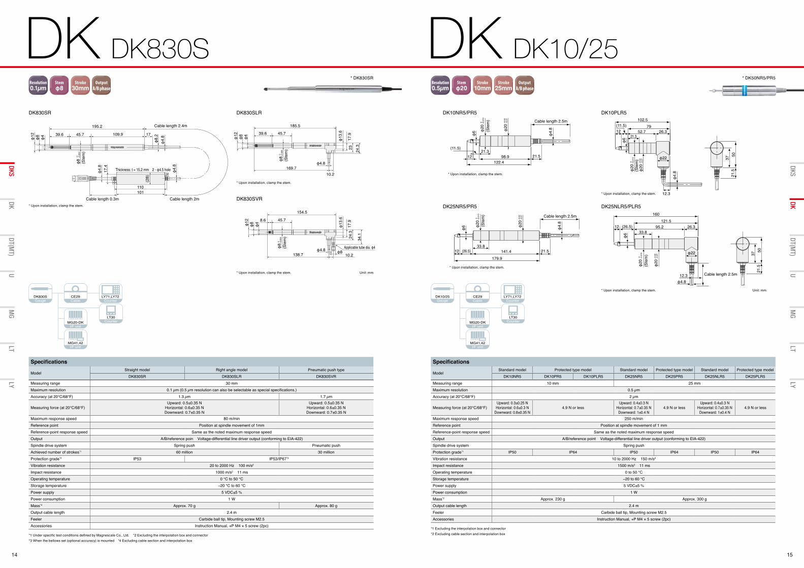
*1 Under specific test conditions defined by Magnescale Co., Ltd. *2 Excluding the interpolation box and connector *3 When the bellows set (optional accuracy) is mounted *4 Excluding cable section and interpolation box
Specifications
ModelStraight model Right angle model Pneumatic push type
DK830SR DK830SLR DK830SVRMeasuring range 30 mmMaximum resolution 0.1 µm (0.5 µm resolution can also be selectable as special specifications.)Accuracy (at 20°C/68°F) 1.3 µm 1.7 µm
Measuring force (at 20°C/68°F)Upward: 0.5±0.35 N
Horizontal: 0.6±0.35 NDownward: 0.7±0.35 N
Upward: 0.5±0.35 NHorizontal: 0.6±0.35 NDownward: 0.7±0.35 N
Maximum response speed 80 m/minReference point Position at spindle movement of 1mmReference-point response speed Same as the noted maximum response speedOutput A/B/reference poin Voltage-differential line driver output (conforming to EIA-422)Spindle drive system Spring push Pneumatic pushAchieved number of strokes*1 60 million 30 millionProtection grade*2 IP53 IP53/IP67*3
Vibration resistance 20 to 2000 Hz 100 m/s2
Impact resistance 1000 m/s2 11 msOperating temperature 0 °C to 50 °CStorage temperature −20 °C to 60 °CPower supply 5 VDC±5 %Power consumption 1 WMass*4 Approx. 70 g Approx. 80 gOutput cable length 2.4 mFeeler Carbide ball tip, Mounting screw M2.5Accessories Instruction Manual, +P M4 × 5 screw (2pc)
Resolution0.1µm
Resolution0.5µm
Resolution1µm
Resolution5µm
Stemφ8
Stemφ20
Stemφ32
Stroke5mm
Stroke10mm
Stroke12mm
CommunicationCC-Link
OutputBCD
I/O出力 OutputRS-232C
OutputGo/no-gojudgment
CommunicationEthernet
Stroke32mm
Stroke60mm
Stroke25mm
Stroke30mm
Stroke50mm
Stroke100mm
Stroke110mm
Stroke155mm
Stroke205mm
OutputA/B phase
A/B出力MT接続時
*1 Excluding the interpolation box and connector *2 Excluding cable section and interpolation box
Specifications
ModelStandard model Protected type model Standard model Protected type model Standard model Protected type model
DK10NR5 DK10PR5 DK10PLR5 DK25NR5 DK25PR5 DK25NLR5 DK25PLR5Measuring range 10 mm 25 mmMaximum resolution 0.5 µmAccuracy (at 20°C/68°F) 2 µm
Measuring force (at 20°C/68°F)Upward: 0.3±0.25 NHorizontal: 0.6±0.3 N
Downward: 0.8±0.35 N4.9 N or less
Upward: 0.4±0.3 NHorizontal: 0.7±0.35 N
Downward: 1±0.4 N4.9 N or less
Upward: 0.4±0.3 NHorizontal: 0.7±0.35 N
Downward: 1±0.4 N4.9 N or less
Maximum response speed 250 m/minReference point Position at spindle movement of 1 mmReference-point response speed Same as the noted maximum response speedOutput A/B/reference point Voltage-differential line driver output (conforming to EIA-422)Spindle drive system Spring pushProtection grade*1 IP50 IP64 IP50 IP64 IP50 IP64Vibration resistance 10 to 2000 Hz 150 m/s2
Impact resistance 1500 m/s2 11 msOperating temperature 0 to 50 °CStorage temperature −20 to 60 °CPower supply 5 VDC±5 %Power consumption 1 WMass*2 Approx. 230 g Approx. 300 gOutput cable length 2.4 mFeeler Carbide ball tip, Mounting screw M2.5Accessories Instruction Manual, +P M4 × 5 screw (2pc)
Resolution0.1µm
Resolution0.5µm
Resolution1µm
Resolution5µm
Stemφ8
Stemφ20
Stemφ32
Stroke5mm
Stroke10mm
Stroke12mm
CommunicationCC-Link
OutputBCD
I/O出力 OutputRS-232C
OutputGo/no-gojudgment
CommunicationEthernet
Stroke32mm
Stroke60mm
Stroke25mm
Stroke30mm
Stroke50mm
Stroke100mm
Stroke110mm
Stroke155mm
Stroke205mm
OutputA/B phase
A/B出力MT接続時
φ13
.6
17.9
24.3
34.1
φ4φ8φ12 8.6 45.7
154.5
Applicable tube dia. φ4φ4.8 φ810.2138.7
φ4.
8φ
8.217109.9
Cable length 2.4m
φ4
φ8
φ12 39.6 45.7
195.2
φ13
.6
17.9
23 24.3
φ4φ8
φ12 39.6 45.7
185.5
φ4.8
10.2169.7
(28)
101110
Cable length 0.3m
Thickness: t = 15.2 mm 2 - φ4.5 hole
Cable length 2m
φ4.
817
.4
φ4.
8(Ste
m)
0 −0.0
09φ
8 (Ste
m)
0 −0.0
09φ
8(S
tem
)
0 −0.0
09φ
8
DK830SR DK830SLR
DK830SVR
Unit: mm
* DK830SR
* Upon installation, clamp the stem.
* Upon installation, clamp the stem.
* Upon installation, clamp the stem.
12.3
φ6
φ22
φ4.8
160121.5
26.395.2(26.5)1233.8
Cable length 2.5m
0 −0.0
13φ
20(S
tem
)
Cable length 2.5m
φ4.
8
98.9
−0.0
2−0
.07
φ20
122.4
(11.5)
12
φ6
21.521.3
φ6
179.9
21.5141.4(26.5)1233.8
(Ste
m) Cable length 2.5m
φ4.
8
−0.0
2−0
.07
φ20
0 −0.0
13φ
20
0 −0.0
13φ
20
5037
φ4.
8
102.5
12
12.3
φ22
φ6
7926.352.7
(11.5)
21.3
(Ste
m)
21.5
5037
21.5
−0.0
2−0
.07
φ20
0 −0.0
13φ
20(S
tem
)
−0.0
2−0
.07
φ20
12.3
φ6
φ22
φ4.8
160121.5
26.395.2(26.5)1233.8
Cable length 2.5m
0 −0.0
13φ
20(S
tem
)
Cable length 2.5m
φ4.
8
98.9
−0.0
2−0
.07
φ20
122.4
(11.5)
12
φ6
21.521.3
φ6
179.9
21.5141.4(26.5)1233.8
(Ste
m) Cable length 2.5m
φ4.
8
−0.0
2−0
.07
φ20
0 −0.0
13φ
20
0 −0.0
13φ
20
5037
φ4.
8
102.5
12
12.3
φ22
φ6
7926.352.7
(11.5)
21.3
(Ste
m)
21.5
5037
21.5
−0.0
2−0
.07
φ20
0 −0.0
13φ
20(S
tem
)
−0.0
2−0
.07
φ20
DK25NR5/PR5
DK10NR5/PR5
Unit: mm
* DK50NR5/PR5
* Upon installation, clamp the stem.
12.3
φ6
φ22
φ4.8
160121.5
26.395.2(26.5)1233.8
Cable length 2.5m
0 −0.0
13φ
20(S
tem
)
Cable length 2.5m
φ4.
8
98.9
−0.0
2−0
.07
φ20
122.4
(11.5)
12
φ6
21.521.3
φ6
179.9
21.5141.4(26.5)1233.8
(Ste
m) Cable length 2.5m
φ4.
8
−0.0
2−0
.07
φ20
0 −0.0
13φ
20
0 −0.0
13φ
20
5037
φ4.
8
102.5
12
12.3
φ22
φ6
7926.352.7
(11.5)
21.3
(Ste
m)
21.5
5037
21.5
−0.0
2−0
.07
φ20
0 −0.0
13φ
20(S
tem
)
−0.0
2−0
.07
φ20
DK10PLR5
* Upon installation, clamp the stem.
* Upon installation, clamp the stem.
12.3
φ6
φ22
φ4.8
160121.5
26.395.2(26.5)1233.8
Cable length 2.5m
0 −0.0
13φ
20(S
tem
)
Cable length 2.5m
φ4.
8
98.9
−0.0
2−0
.07
φ20
122.4
(11.5)
12
φ6
21.521.3
φ6
179.9
21.5141.4(26.5)1233.8
(Ste
m) Cable length 2.5m
φ4.
8
−0.0
2−0
.07
φ20
0 −0.0
13φ
20
0 −0.0
13φ
20
5037
φ4.
8
102.5
12
12.3
φ22
φ6
7926.352.7
(11.5)
21.3
(Ste
m)
21.5
5037
21.5
−0.0
2−0
.07
φ20
0 −0.0
13φ
20(S
tem
)
−0.0
2−0
.07
φ20
DK25NLR5/PLR5
* Upon installation, clamp the stem.
16 17
DK DK50/100 DK DK155/205
DT(MT)
UMG
LTLY
DKSDK
DT(MT)
UMG
LTLY
DKSDK
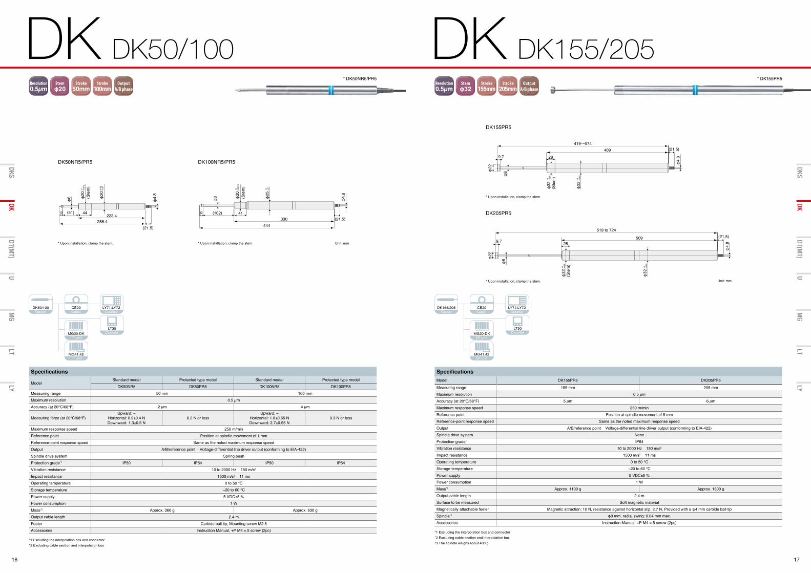
*1 Excluding the interpolation box and connector *2 Excluding cable section and interpolation box
Specifications
ModelStandard model Protected type model Standard model Protected type model
DK50NR5 DK50PR5 DK100NR5 DK100PR5Measuring range 50 mm 100 mmMaximum resolution 0.5 µmAccuracy (at 20°C/68°F) 2 µm 4 µm
Measuring force (at 20°C/68°F)Upward: −
Horizontal: 0.9±0.4 NDownward: 1.3±0.5 N
6.2 N or lessUpward: −
Horizontal: 1.8±0.65 NDownward: 2.7±0.55 N
9.3 N or less
Maximum response speed 250 m/minReference point Position at spindle movement of 1 mmReference-point response speed Same as the noted maximum response speedOutput A/B/reference point Voltage-differential line driver output (conforming to EIA-422)Spindle drive system Spring pushProtection grade*1 IP50 IP64 IP50 IP64Vibration resistance 10 to 2000 Hz 150 m/s2
Impact resistance 1500 m/s2 11 msOperating temperature 0 to 50 °CStorage temperature −20 to 60 °CPower supply 5 VDC±5 %Power consumption 1 WMass*2 Approx. 360 g Approx. 630 gOutput cable length 2.4 mFeeler Carbide ball tip, Mounting screw M2.5Accessories Instruction Manual, +P M4 × 5 screw (2pc)
Resolution0.1µm
Resolution0.5µm
Resolution1µm
Resolution5µm
Stemφ8
Stemφ20
Stemφ32
Stroke5mm
Stroke10mm
Stroke12mm
CommunicationCC-Link
OutputBCD
I/O出力 OutputRS-232C
OutputGo/no-gojudgment
CommunicationEthernet
Stroke32mm
Stroke60mm
Stroke25mm
Stroke30mm
Stroke50mm
Stroke100mm
Stroke110mm
Stroke155mm
Stroke205mm
OutputA/B phase
A/B出力MT接続時
*1 Excluding the interpolation box and connector *2 Excluding cable section and interpolation box *3 The spindle weighs about 400 g.
SpecificationsModel DK155PR5 DK205PR5
Measuring range 155 mm 205 mmMaximum resolution 0.5 µmAccuracy (at 20°C/68°F) 5 µm 6 µmMaximum response speed 250 m/minReference point Position at spindle movement of 5 mmReference-point response speed Same as the noted maximum response speedOutput A/B/reference point Voltage-differential line driver output (conforming to EIA-422)Spindle drive system NoneProtection grade*1 IP64Vibration resistance 10 to 2000 Hz 150 m/s2
Impact resistance 1500 m/s2 11 msOperating temperature 0 to 50 °CStorage temperature −20 to 60 °CPower supply 5 VDC±5 %Power consumption 1 WMass*2 Approx. 1100 g Approx. 1300 gOutput cable length 2.4 mSurface to be measured Soft magnetic materialMagnetically attachable feeler Magnetic attraction: 10 N, resistance against horizontal slip: 2.7 N, Provided with a φ4 mm carbide ball tipSpindle*3 φ8 mm, radial swing: 0.04 mm max.Accessories Instruction Manual, +P M4 × 5 screw (2pc)
Resolution0.1µm
Resolution0.5µm
Resolution1µm
Resolution5µm
Stemφ8
Stemφ20
Stemφ32
Stroke5mm
Stroke10mm
Stroke12mm
CommunicationCC-Link
OutputBCD
I/O出力 OutputRS-232C
OutputGo/no-gojudgment
CommunicationEthernet
Stroke32mm
Stroke60mm
Stroke25mm
Stroke30mm
Stroke50mm
Stroke100mm
Stroke110mm
Stroke155mm
Stroke205mm
OutputA/B phase
A/B出力MT接続時
DK50/100Gauge Cable
I/F unit
I/F unit
Counter
Counter
DK155/205Gauge Cable
I/F unit
I/F unit
Counter
Counter
DK50NR5/PR5 DK100NR5/PR5
Unit: mm
(21.5)
(51)
φ6
286.4223.4
12 44
(Ste
m)
φ4.8
−0.02
−0.07
φ20
0 −0.013
φ20
(Ste
m)
(21.5)(102)12
φ8
444330
41
φ4.8
0 −0.013
φ20
0 −0.1
φ25
* DK50NR5/PR5
* Upon installation, clamp the stem.* Upon installation, clamp the stem.
DK205PR5
DK155PR5
* DK155PR5
Unit: mm
(21.5)
φ22
409
φ8
9.7
419~574
28
(Ste
m)
φ4.8
0 −0.05
φ32
0 −0.05
φ32
(21.5)
φ22
509
φ8
289.7
519 to 724
φ4.8
0 −0.05
(Ste
m)
0 −0.05
φ32
φ32
* Upon installation, clamp the stem.
* Upon installation, clamp the stem.
A
B
Integral multiple of 50 ns or 100 ns
50ns100ns300ns500ns
200ns400ns1.2μs2μs
Phase A/BMinimum phase difference
Counter’s permissiblefrequency
5MHz2.5MHz833kHz500kHz
Resolution 0.1 μm80m/min42m/min14m/min8.4m/min
Phase A single cycleMaximum response speed
Resolution 0.5 μm250m/min100m/min33m/min20m/min
DK800SA standard productDK800SB standard product
Special specificationsSpecial specifications
Remarks
Alarm sectionPhase A/B is in high impedance state.
19.5 m or less (excluding 2.5 m standard cable)
Line driver
Output: A/B/reference point
Receiver Line receiver AM26C32 or equivalent
A
BReference-pointoutput
A
B50 ns
200 ns (5 MHz)
DK800SA output signal at maximum response speed (at approx. 80 m/min)
A
B100 ns
400 ns (2.5 MHz)
DK800SB output signal at maximum response speed (at approx. 42 m/min)
A
B50 ns
200 ns (5 MHz)
DK10/25/100/155/205/110 output signal at maximumresponse speed (at approx. 250 m/min)
PR A
VP
EXE
AIRAIR
Pressuresource
Mist separator
Air filter
Speed controller
Regulator Solenoid valve Vacuum ejector
* If extending the cable (Magnescale-specific cable), the supply voltage should be +5 V ±5% at the extension destination. *For an extension cable with spread-out end, use the CE22 Series.
Fig. 2 Pneumatic circuit (vacuum suction)Fig. 1 Pneumatic circuit (pneumatic push)
PR A
Regulator Solenoid valve Precision regulatorPressure
source
Mist separator
Air filter Speed controller
18 19
DK DK110
DT(MT)
UMG
LTLY
DKSDK
DT(MT)
UMG
LTLY
DKSDK
DK110Gauge Cable
I/F unit
I/F unit
Counter
Counter
*1 Excluding the interpolation box and connector *2 Excluding cable section and interpolation box
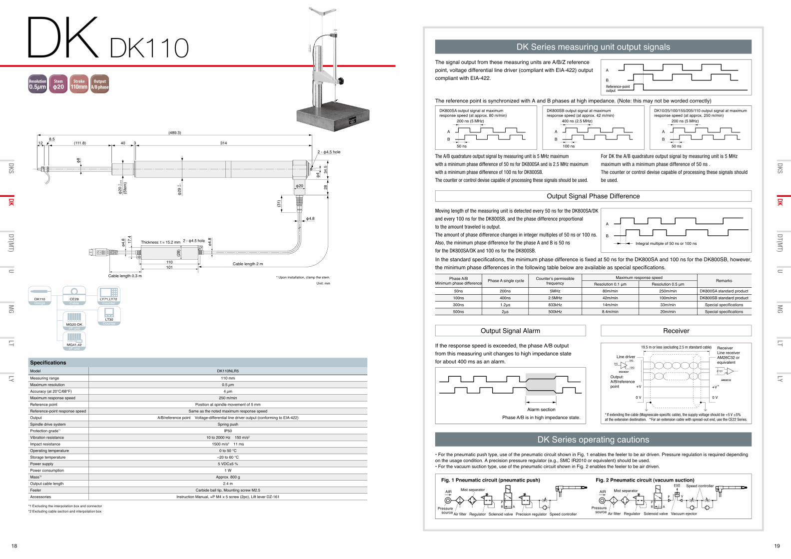
Specifi cationsModel DK110NLR5
Measuring range 110 mmMaximum resolution 0.5 µmAccuracy (at 20°C/68°F) 4 µmMaximum response speed 250 m/minReference point Position at spindle movement of 5 mmReference-point response speed Same as the noted maximum response speedOutput A/B/reference point Voltage-differential line driver output (conforming to EIA-422)Spindle drive system Spring pushProtection grade*1 IP50Vibration resistance 10 to 2000 Hz 150 m/s2
Impact resistance 1500 m/s2 11 msOperating temperature 0 to 50 °CStorage temperature −20 to 60 °CPower supply 5 VDC±5 %Power consumption 1 WMass*2 Approx. 800 gOutput cable length 2.4 mFeeler Carbide ball tip, Mounting screw M2.5Accessories Instruction Manual, +P M4 × 5 screw (2pc), Lift lever DZ-161
Resolution0.1µm
Resolution0.5µm
Resolution1µm
Resolution5µm
Stemφ8
Stemφ20
Stemφ32
Stroke5mm
Stroke10mm
Stroke12mm
CommunicationCC-Link
OutputBCD
I/O出力 OutputRS-232C
OutputGo/no-gojudgment
CommunicationEthernet
Stroke32mm
Stroke60mm
Stroke25mm
Stroke30mm
Stroke50mm
Stroke100mm
Stroke110mm
Stroke155mm
Stroke205mm
OutputA/B phase
A/B出力MT接続時
φ4.8
8.512 (111.8)
(489.3)
314
2 - φ4.5 hole
φ8
3
0 −0.1
φ29
0 −0.0
13φ
20
φ4 34
.528φ20
(31)
Cable length 2 m
40
(Ste
m)
(28)
101110
Cable length 0.3 m
Thickness: t = 15.2 mm 2 - φ4.5 hole
ø4.8 17
.4
ø4.8
Unit: mm
* Upon installation, clamp the stem.
DK Series measuring unit output signals
DK Series operating cautions
The signal output from these measuring units are A/B/Z reference point, voltage differential line driver (compliant with EIA-422) output compliant with EIA-422.
• For the pneumatic push type, use of the pneumatic circuit shown in Fig. 1 enables the feeler to be air driven. Pressure regulation is required depending on the usage condition. A precision pressure regulator (e.g., SMC IR2010 or equivalent) should be used. • For the vacuum suction type, use of the pneumatic circuit shown in Fig. 2 enables the feeler to be air driven.
Moving length of the measuring unit is detected every 50 ns for the DK800SA/DK
and every 100 ns for the DK800SB, and the phase difference proportional
to the amount traveled is output.
The amount of phase difference changes in integer multiples of 50 ns or 100 ns.
Also, the minimum phase difference for the phase A and B is 50 ns
for the DK800SA/DK and 100 ns for the DK800SB.
If the response speed is exceeded, the phase A/B output from this measuring unit changes to high impedance state for about 400 ms as an alarm.
The A/B quadrature output signal by measuring unit is 5 MHz maximum
with a minimum phase difference of 50 ns for DK800SA and is 2.5 MHz maximum
with a minimum phase difference of 100 ns for DK800SB.
The counter or control devise capable of processing these signals should be used.
For DK the A/B quadrature output signal by measuring unit is 5 MHz
maximum with a minimum phase difference of 50 ns .
The counter or control devise capable of processing these signals should
be used.
In the standard specifi cations, the minimum phase difference is fi xed at 50 ns for the DK800SA and 100 ns for the DK800SB, however, the minimum phase differences in the following table below are available as special specifi cations.
The reference point is synchronized with A and B phases at high impedance. (Note: this may not be worded correctly)
Output Signal Phase Difference
Output Signal Alarm Receiver
20 21
DT DT512/12 DT DT32
DT(MT)
UMG
LTLY
DKSDK
DT(MT)
UMG
LTLY
DKSDK
*1 Under specifi c test conditions defi ned by Magnescale Co., Ltd. *2 Excluding the connector *3 Excluding cable section
*1 At input air pressure of 1.96 × 10⁵ Pa with speed controller open (DT32N) *2 At input air pressure of 2.35 × 10⁵ Pa with speed controller open *3 Based on the Magnescale-specifi ed evaluation method *4 Excluding the connector *5 Excluding cable section
Gauge Adapter
Interpolator
I/F unit
Counter
Counter
DT12Gauge Adapter
Interpolator
I/F unit
Counter
Counter
DT32Gauge Adapter
Interpolator
I/F unit
Counter
Counter
Resolution0.1µm
Resolution0.5µm
Resolution1µm
Resolution5µm
Stemφ8
Stemφ20
Stemφ32
Stroke5mm
Stroke10mm
Stroke12mm
CommunicationCC-Link
OutputBCD
I/O出力 OutputRS-232C
OutputGo/no-gojudgment
CommunicationEthernet
Stroke32mm
Stroke60mm
Stroke25mm
Stroke30mm
Stroke50mm
Stroke100mm
Stroke110mm
Stroke155mm
Stroke205mm
OutputA/B phase
A/B出力MT接続時
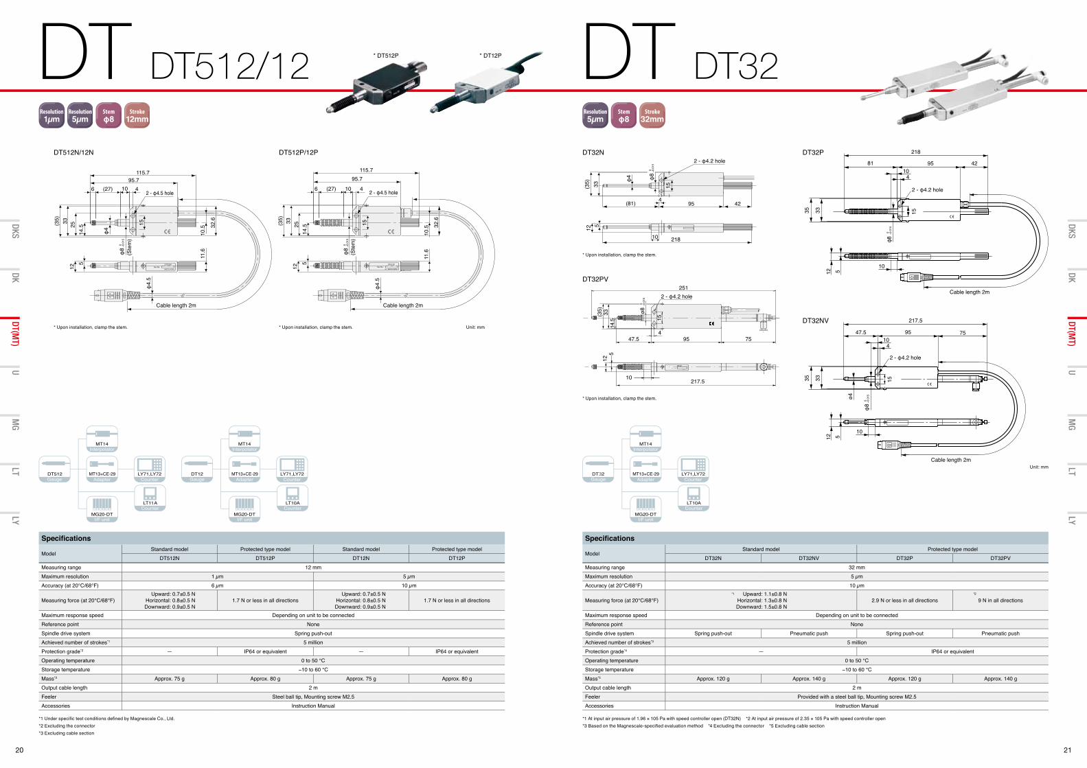
Specifi cations
ModelStandard model Protected type model Standard model Protected type model
DT512N DT512P DT12N DT12PMeasuring range 12 mmMaximum resolution 1 µm 5 µmAccuracy (at 20°C/68°F) 6 µm 10 µm
Measuring force (at 20°C/68°F) Upward: 0.7±0.5 N
Horizontal: 0.8±0.5 NDownward: 0.9±0.5 N
1.7 N or less in all directionsUpward: 0.7±0.5 N
Horizontal: 0.8±0.5 NDownward: 0.9±0.5 N
1.7 N or less in all directions
Maximum response speed Depending on unit to be connectedReference point NoneSpindle drive system Spring push-outAchieved number of strokes*1 5 millionProtection grade*2 — IP64 or equivalent — IP64 or equivalentOperating temperature 0 to 50 °CStorage temperature −10 to 60 °CMass*3 Approx. 75 g Approx. 80 g Approx. 75 g Approx. 80 gOutput cable length 2 mFeeler Steel ball tip, Mounting screw M2.5Accessories Instruction Manual
Specifi cations
ModelStandard model Protected type model
DT32N DT32NV DT32P DT32PVMeasuring range 32 mmMaximum resolution 5 µmAccuracy (at 20°C/68°F) 10 µm
Measuring force (at 20°C/68°F) Upward: 1.1±0.8 N
Horizontal: 1.3±0.8 NDownward: 1.5±0.8 N
2.9 N or less in all directions 9 N in all directions
Maximum response speed Depending on unit to be connectedReference point NoneSpindle drive system Spring push-out Pneumatic push Spring push-out Pneumatic pushAchieved number of strokes*3 5 millionProtection grade*4 — IP64 or equivalentOperating temperature 0 to 50 °CStorage temperature −10 to 60 °CMass*5 Approx. 120 g Approx. 140 g Approx. 120 g Approx. 140 gOutput cable length 2 mFeeler Provided with a steel ball tip, Mounting screw M2.5Accessories Instruction Manual
*1 *2
DT512N/12N DT512P/12P
Unit: mm
φ4.
5
(27)6 4
10.5
2 - φ4.5 hole
33 2514
.5 15 32.6
5
(35)
11.6
12
95.7115.7
10
(Ste
m)
0 −0.0
15φ
8
Cable length 2m
φ4.
5
(27)6 4
φ4
10.5
2 - φ4.5 hole
33 2514
.5 15 32.6
5
(35)
11.6
12
95.7115.7
10
Cable length 2m
(Ste
m)
0 −0.0
15φ
8
* Upon installation, clamp the stem.* Upon installation, clamp the stem.
* DT512P * DT12P
10 218
512
2 - φ4.2 hole
(81) 95 42
(35) 33
φ4
4
15
10 217.5
512
4
2 - φ4.2 hole251
9547.5 75
(35) 33 ø8
0 −0.0
15
14.5 15
0 −0.0
15φ
8
10
35 33 15
217.5
47.5 7595
410
12 5
ø4
Cable length 2m
2 - φ4.2 hole
0 −0.0
15φ
8
218
81 95 42
10
35 33 15
410
12 5
Cable length 2m
2 - φ4.2 hole
0 −0.0
15φ8
DT32N
DT32PV
DT32NV
DT32P
Unit: mm
* Upon installation, clamp the stem.
* Upon installation, clamp the stem.
10 218
512
2 - φ4.2 hole
(81) 95 42
(35) 33
φ4
4
15
10 217.55
12
4
2 - φ4.2 hole251
9547.5 75
(35) 33 ø8
0 −0.0
15
14.5 15
0 −0.0
15φ
8
22 23
MT MT12/13/14 U U Series
DT(MT)
UMG
LTLY
DKSDK
DT(MT)
UMG
LTLY
DKSDK
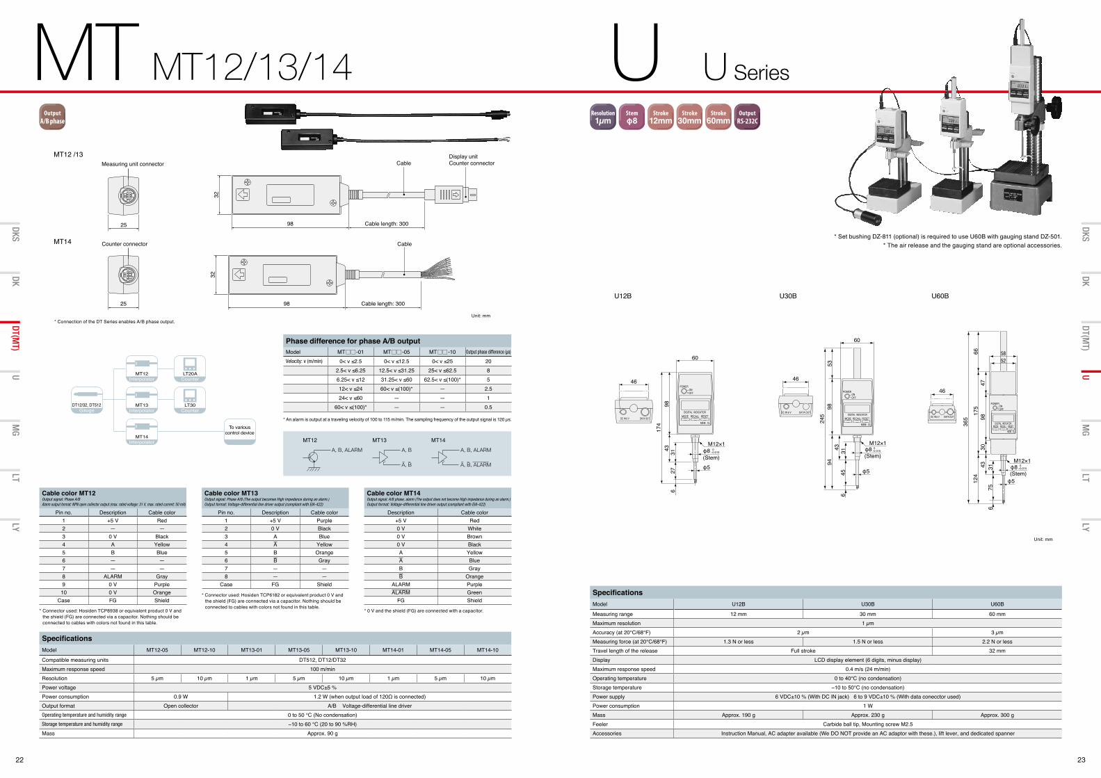
SpecificationsModel MT12-05 MT12-10 MT13-01 MT13-05 MT13-10 MT14-01 MT14-05 MT14-10
Compatible measuring units DT512, DT12/DT32Maximum response speed 100 m/minResolution 5 µm 10 µm 1 µm 5 µm 10 µm 1 µm 5 µm 10 µmPower voltage 5 VDC±5 %Power consumption 0.9 W 1.2 W (when output load of 120Ω is connected)Output format Open collector A/B Voltage-differential line driverOperating temperature and humidity range 0 to 50 °C (No condensation)Storage temperature and humidity range −10 to 60 °C (20 to 90 %RH)Mass Approx. 90 g
* An alarm is output at a traveling velocity of 100 to 115 m/min. The sampling frequency of the output signal is 120 µs.
* Connector used: Hosiden TCP8938 or equivalent product 0 V and the shield (FG) are connected via a capacitor. Nothing should be connected to cables with colors not found in this table.
* Connector used: Hosiden TCP6182 or equivalent product 0 V and the shield (FG) are connected via a capacitor. Nothing should be connected to cables with colors not found in this table.
* 0 V and the shield (FG) are connected with a capacitor.
Phase difference for phase A/B outputModel MT -01 MT -05 MT -10 Output phase difference (µs)
Velocity: v (m/min) 0< v ≤2.5 0< v ≤12.5 0< v ≤25 202.5< v ≤6.25 12.5< v ≤31.25 25< v ≤62.5 86.25< v ≤12 31.25< v ≤60 62.5< v ≤(100)* 512< v ≤24 60< v ≤(100)* — 2.524< v ≤60 — — 1
60< v ≤(100)* — — 0.5
Cable color MT12Output signal: Phase A/B Alarm output format: NPN open collector output (max. rated voltage: 31 V, max. rated current: 50 mA)
Pin no. Description Cable color1 +5 V Red2 — —3 0 V Black4 A Yellow5 B Blue6 — —7 — —8 ALARM Gray9 0 V Purple
10 0 V OrangeCase FG Shield
Cable color MT13Output signal: Phase A/B (The output becomes High impedance during an alarm.)Output format: Voltage-differential line driver output (compliant with EIA-422)
Pin no. Description Cable color1 +5 V Purple2 0 V Black3 A Blue4 A Yellow5 B Orange6 B Gray7 — —8 — —
Case FG Shield
Cable color MT14Output signal: A/B phase, alarm (The output does not become High impedance during an alarm.)Output format: Voltage-differential line driver output (compliant with EIA-422)
Description Cable color+5 V Red0 V White0 V Brown0 V BlackA YellowA BlueB GrayB Orange
ALARM PurpleALARM Green
FG Shield
Gauge Counter
CounterInterpolator
Interpolator
Interpolator
SpecificationsModel U12B U30B U60B
Measuring range 12 mm 30 mm 60 mmMaximum resolution 1 µmAccuracy (at 20°C/68°F) 2 µm 3 µmMeasuring force (at 20°C/68°F) 1.3 N or less 1.5 N or less 2.2 N or lessTravel length of the release Full stroke 32 mmDisplay LCD display element (6 digits, minus display)Maximum response speed 0.4 m/s (24 m/min)Operating temperature 0 to 40°C (no condensation)Storage temperature −10 to 50°C (no condensation)Power supply 6 VDC±10 % (With DC IN jack) 6 to 9 VDC±10 % (With data conecctor used)Power consumption 1 WMass Approx. 190 g Approx. 230 g Approx. 300 gFeeler Carbide ball tip, Mounting screw M2.5Accessories Instruction Manual, AC adapter available (We DO NOT provide an AC adaptor with these.), lift lever, and dedicated spanner
Resolution0.1µm
Resolution0.5µm
Resolution1µm
Resolution5µm
Stemφ8
Stemφ20
Stemφ32
Stroke5mm
Stroke10mm
Stroke12mm
CommunicationCC-Link
OutputBCD
I/O出力 OutputRS-232C
OutputGo/no-gojudgment
CommunicationEthernet
Stroke32mm
Stroke60mm
Stroke25mm
Stroke30mm
Stroke50mm
Stroke100mm
Stroke110mm
Stroke155mm
Stroke205mm
OutputA/B phase
A/B出力MT接続時
To various control device
MT12 /13
MT14
Unit: mm
Measuring unit connector
25
3298 Cable length: 300
CableDisplay unitCounter connector
Counter connector
25
32
98 Cable length: 300
Cable
MT12 MT13 MT14A, B, ALARM A, B
A, B_ _ ________ _
A, B, ALARM
A, B, ALARM
U12B U30B U60B
Unit: mm
46
φ5
M12×1φ8 0
−0.015
60
43 3145
9498
53245
6
46
M12×1φ8 0
−0.015
φ5
58
365
66175
124
4798
3031
756
43
52
46
φ8(Stem) φ5
M12×10−0.015
60
314398
174
276
(Stem)
(Stem)
* Set bushing DZ-811 (optional) is required to use U60B with gauging stand DZ-501. * The air release and the gauging stand are optional accessories.
* Connection of the DT Series enables A/B phase output.
24 25
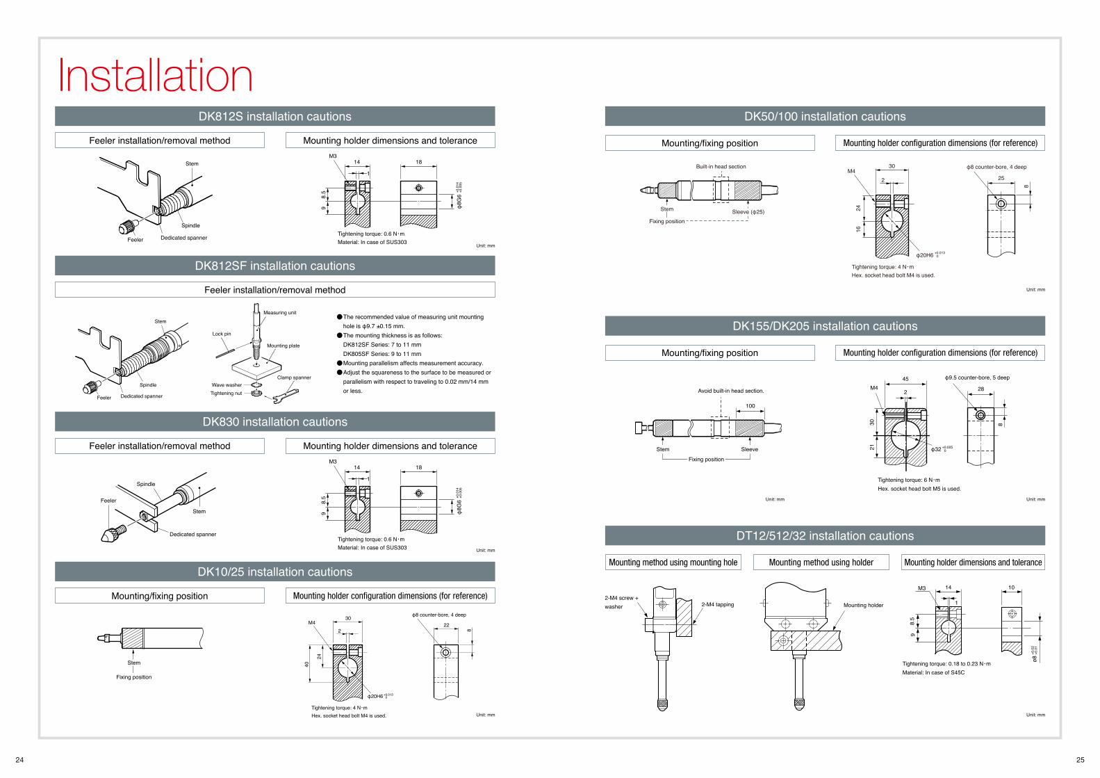
Installation
The recommended value of measuring unit mounting hole is φ9.7 ±0.15 mm. The mounting thickness is as follows: DK812SF Series: 7 to 11 mm DK805SF Series: 9 to 11 mm Mounting parallelism affects measurement accuracy. Adjust the squareness to the surface to be measured or parallelism with respect to traveling to 0.02 mm/14 mm or less.
DK812S installation cautions
DK830 installation cautions
DK10/25 installation cautions
DK812SF installation cautions
Tightening torque: 0.6 N・mMaterial: In case of SUS303
M314 18
8.5
1
φ8G
6+0
.014
+0.0
05
Feeler
Spindle
Stem
Dedicated spanner9
Feeler
Spindle
Stem
Dedicated spannerTightening torque: 0.6 N・mMaterial: In case of SUS303
M314 18
8.5
1
φ8G
6+0
.014
+0.0
05
Feeler
Spindle
Stem
Dedicated spanner
Lock pin
Measuring unit
Mounting plate
Wave washerTightening nut
Clamp spanner
Tightening torque: 0.6 N・mMaterial: In case of SUS303
M314 18
8.5
1
φ8G
6+0
.014
+0.0
05
Feeler
Spindle
Stem
Dedicated spanner
9
Tightening torque: 0.6 N・mMaterial: In case of SUS303
M314 18
8.5
1
φ8G
6+0
.014
+0.0
05
Feeler
Spindle
Stem
Dedicated spanner
9
Unit: mm
Unit: mm
Unit: mm
Feeler installation/removal method
Feeler installation/removal method
Mounting/fixing position
Feeler installation/removal method
Mounting holder dimensions and tolerance
Mounting holder dimensions and tolerance
Mounting holder configuration dimensions (for reference)
DK50/100 installation cautions
DK155/DK205 installation cautions
DT12/512/32 installation cautions
Stem
Fixing position
Tightening torque: 4 N・mHex. socket head bolt M4 is used.
M430
2 25
2416
φ20H6
φ8 counter-bore, 4 deep
+0.013 0
8
Sleeve (φ25)
Built-in head section
Stem
Fixing position
Tightening torque: 4 N・mHex. socket head bolt M4 is used.
M430
222
40
24
φ20H6
φ8 counter-bore, 4 deep
8
+0.0130
Stem
Fixing position
Tightening torque: 4 N・mHex. socket head bolt M4 is used.
M430
222
40
24
φ20H6
φ8 counter-bore, 4 deep
8
+0.0130
Tightening torque: 6 N・mHex. socket head bolt M5 is used.
M445
100
2 28
3021
φ9.5 counter-bore, 5 deep
8
Avoid built-in head section.
Stem Sleeve
Fixing position
φ32 +0.025 0
14M3 10
1
98.
5
ø8+0
.01
+0.0
2
Tightening torque: 0.18 to 0.23 N・mMaterial: In case of S45C
Mounting holder2-M4 tapping2-M4 screw + washer
14M3 10
1
98.
5
ø8+0
.01
+0.0
2
Tightening torque: 0.18 to 0.23 N・mMaterial: In case of S45C
Mounting holder2-M4 tapping2-M4 screw + washer
14M3 10
1
98.
5
ø8+0
.01
+0.0
2
Tightening torque: 0.18 to 0.23 N・mMaterial: In case of S45C
Mounting holder2-M4 tapping2-M4 screw + washer
Tightening torque: 6 N・mHex. socket head bolt M5 is used.
M445
100
2 28
3021
φ9.5 counter-bore, 5 deep
8
Avoid built-in head section.
Stem Sleeve
Fixing position
φ32 +0.025 0
Stem
Fixing position
Tightening torque: 4 N・mHex. socket head bolt M4 is used.
M430
2 25
2416
φ20H6
φ8 counter-bore, 4 deep
+0.013 0
8
Sleeve (φ25)
Built-in head section
Unit: mm
Unit: mm Unit: mm
Unit: mm
Mounting/fixing position
Mounting/fixing position
Mounting method using mounting hole Mounting method using holder
Mounting holder configuration dimensions (for reference)
Mounting holder configuration dimensions (for reference)
Mounting holder dimensions and tolerance
26 27
MG40 Series 28
MG10/20/30 29
Interface unit
28 29
MG MGMG40 Series MG10/20/30
DT(MT)
UMG
LTLY
DKSDK
DT(MT)
UMG
LTLY
DKSDK
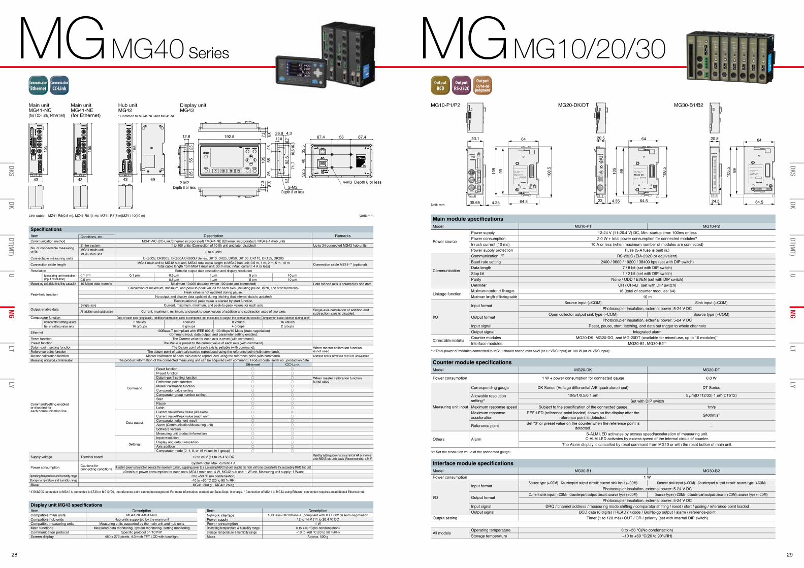
Display unit MG43 specifi cationsItem Description Item DescriptionCompatible main units MG41-NE/MG41-NC Network interface 100Base-TX/10Base-T (compliant with IEEE802.3) Auto-negotiationCompatible hub units Hub units supported by the main unit Power supply 12 to 14 V (11 to 26.4 V) DCCompatible measuring units Measuring units supported by the main unit and hub units Power consumption 4 WMain functions Measured data monitoring, system monitoring, setting monitoring Operating temperature & humidity range 0 to +40 °C(no condensation)Communication protocol Specifi c protocol on TCP/IP Storage temperature & humidity range −10 to +60 °C(20 to 90 %RH)Screen display 480 x 272 pixels, 4.3-inch TFT LCD with backlight Mass Approx. 500 g
Main module specifi cationsModel MG10-P1 MG10-P2
Power source
Power supply 12-24 V (11-26.4 V) DC, Min. startup time: 100ms or lessPower consumption 2.0 W + total power consumption for connected modules*1
Inrush current (10 ms) 10 A or less (when maximum number of modules are connected)Power supply protection Fuse (5-A fuse is built in.)
Communication
Communication I/F RS-232C (EIA-232C or equivalent)Baud rate setting 2400 / 9600 / 19200 / 38400 bps (set with DIP switch)Data length 7 / 8 bit (set with DIP switch)Stop bit 1 / 2 bit (set with DIP switch)Parity None / ODD / EVEN (set with DIP switch)Delimiter CR / CR+LF (set with DIP switch)
Linkage functionMaximum number of linkages 16 (total of counter modules: 64)Maximum length of linking cable 10 m
I/O
Input formatSource input (+COM) Sink input (−COM)
Photocoupler insulation, external power: 5-24 V DC
Output formatOpen collector output sink type (−COM) Source type (+COM)
Photocoupler insulation, external power: 5-24 V DCInput signal Reset, pause, start, latching, and data out trigger to whole channelsOutput signal Integrated alarm
Connectable modulesCounter modules MG20-DK, MG20-DG, and MG-20DT (available for mixed use, up to 16 modules)*1
Interface modules MG30‐B1, MG30‐B2 *1
*1: Total power of modules connected to MG10 should not be over 54W (at 12 VDC input) or 108 W (at 24 VDC input).
Counter module specifi cationsModel MG20-DK MG20-DT
Power consumption 1 W + power consumption for connected gauge 0.8 W
Measuring unit input
Corresponding gauge DK Series (Voltage differential A/B quadrature input) DT Series
Allowable resolution setting*2
10/5/1/0.5/0.1 µm 5 µm(DT12/32) 1 µm(DT512)Set with DIP switch
Maximum response speed Subject to the specifi cation of the connected gauge 1m/sMaximum response acceleration
REF-LED (reference-point loaded) shows on the display after the reference point is detected. 2400m/s2
Reference point Set “0” or preset value on the counter when the reference point is detected. —
Others AlarmS-ALM LED activates by excess speed/acceleration of measuring unit. C-ALM LED activates by excess speed of the internal circuit of counter.
The Alarm display is cancelled by reset command from MG10 or with the reset button of main unit.
*2: Set the resolution value of the connected gauge.
Interface module specifi cationsModel MG30-B1 MG30-B2Power consumption 1 W
I/O
Input formatSource type (+COM) Counterpart output circuit: current sink input (−COM) Current sink input (+COM) Counterpart output circuit: source type (+COM)
Photocoupler insulation, external power: 5-24 V DC
Output formatCurrent sink input (−COM) Counterpart output circuit: source type (+COM) Source type (+COM) Counterpart output circuit (+COM): source type (−COM)
Photocoupler insulation, external power: 5-24 V DCInput signal DRQ / channel address / measuring mode shifting / comparator shifting / reset / start / posing / reference-point loadedOutput signal BCD data (6 digits) / READY / code / Go/No-go output / alarm / reference-point
Output setting Timer (1 to 128 ms) / OUT / OR / polarity (set with internal DIP switch)
All modelsOperating temperature 0 to +50 °C(No condensation)Storage temperature −10 to +60 °C(20 to 90%RH)
* If DK800S connected to MG40 is connected to LT30 or MG10/20, the reference point cannot be recognized. For more information, contact our Sales Dept. in charge. * Connection of MG41 to MG43 using Ethernet connection requires an additional Ethernet hub.
Specifi cationsItem Description RemarksConditions, etc.Communication method MG41-NC (CC-Link/Ethernet incorporated) / MG41-NE (Ethernet incorporated) / MG42-4 (hub unit)
No. of connectable measuring units
Entire system 1 to 100 units (Connection of 101th unit and later disabled) Up to 24 connected MG42 hub unitsMG41 main unit 0 to 4 unitsMG42 hub unit
Connectable measuring units DK800S, DK830S, DK800A/DK800B Series, DK10, DK25, DK50, DK100, DK110, DK155, DK205
Connection cable length MG41 main unit to MG42 hub unit, MG42 total cable length to MG42 hub unit: 0.5 m, 1 m, 2 m, 5 m, 10 mTotal cable length from MG41 main unit: 30 m max. (Max. current: 4 A or less) Connection cable MZ41-** (optional)
Resolution Settable output data resolution and display resolutionMeasuring unit resolution(Input resolution)
0.1 µm 0.1 µm 0.5 µm 1 µm 5 µm 10 µm0.5 µm — 0.5 µm 1 µm 5 µm 10 µm
Measuring unit data fetching capacity 10 Mbps data transfer Maximum 10,000 data/sec (when 100 axes are connected) Data for one axis is counted as one data.
Peak-hold function
Calculation of maximum, minimum, and peak-to-peak values for each axis (including pause, latch, and start functions)Peak value is not updated during pause.
No output and display data updated during latching (but internal data is updated)Recalculation of peak value is started by start function.
Output-enable dataSingle axis Current, maximum, minimum, and peak-to-peak values for each axis
At addition and subtraction Current, maximum, minimum, and peak-to-peak values of addition and subtraction axes of two axes Single-axis calculation of addition and subtraction axes is disabled.
Comparator function Data of each axis (single axis, addition/subtraction axis) is compared and measured to output the comparator results (Comparator is also latched during latch)Comparator setting values 2 values 4 values 8 values 16 valuesNo. of setting value sets 16 groups 8 groups 4 groups 2 groups
Ethernet 100Base-T (compliant with IEEE 802.3) 100 Mbps/10 Mbps (Auto-negotiation)Command input, data output, and parameter setting enabled.
Reset function The Current value for each axis is reset (with command).Preset function The Value is preset to the current value of each axis (with command).Datum-point setting function The Datum point of each axis is settable (with command). When master calibration function
is not usedReference point function The datum point of each axis can be reproduced using the reference point (with command).Master calibration function Master calibration of each axis can be reproduced using the reference point (with command). Addition and subtraction axes are unavailable.Measuring unit product information The product information of the connected measuring unit can be acquired (with command). Product code, serial no., production date
Command/setting enabled or disabled for each communication line
Ethernet CC-Link
Command
Reset functionPreset functionDatum-point setting function When master calibration function
is not usedReference point functionMaster calibration functionComparator value settingComparator group number settingStartPauseLatch
Data output
Current value/Peak value (All axes)Current value/Peak value (each unit)Comparator judgment resultAlarm (Communication/Measuring unit)Software versionMeasuring unit product information
Settings
Input resolutionDisplay and output resolutionAxis additionComparator mode (2, 4, 8, or 16 values in 1 group)
Supply voltage Terminal board 12 to 24 V (11 to 26.4 V) DC Used by adding power at a current of 4A or more on a six MG42 hub units basis. (Recommended: +24 V)
Power consumption Cautions for connecting conditions
System total: Max. current 4 AIf system power consumption exceeds the maximum current, supplying power to a succeeding MG42 hub unit enables the main unit to be connected to the succeeding MG42 hub unit.
<Details of power consumption for each unit> MG41 main unit: 4 W, MG42 hub unit: 1 W/unit, Measuring unit supply: 1 W/unitOperating temperature and humidity range 0 to +50 °C (no condensation)Storage temperature and humidity range -10 to +60 °C (20 to 90 % RH)Mass MG41: 300 g MG42: 250 g
Resolution0.1µm
Resolution0.5µm
Resolution1µm
Resolution5µm
Stemφ8
Stemφ20
Stemφ32
Stroke5mm
Stroke10mm
Stroke12mm
CommunicationCC-Link
OutputBCD
I/O出力 OutputRS-232C
OutputGo/no-gojudgment
CommunicationEthernet
Stroke32mm
Stroke60mm
Stroke25mm
Stroke30mm
Stroke50mm
Stroke100mm
Stroke110mm
Stroke155mm
Stroke205mm
OutputA/B phase
A/B出力MT接続時
155
43
155
43
67.4 67.458
4032
.532
.5
4-M3 Depth 8 or less
192.812.8
5525
252-M2
Depth 8 or less 2-M2Depth 8 or less
7.3
105
55 92.6
71.7
16.5
6.216
.86.2
7.3 8.5
12.8
25
26.9 4.3
258.
5
155
43 69186 +1
0
93.5
+1 0
103
30
4-φ4.5
155
43
155
43
67.4 67.458
4032
.532
.5
4-M3 Depth 8 or less
192.812.8
5525
252-M2
Depth 8 or less 2-M2Depth 8 or less
7.3
105
55 92.6
71.7
16.5
6.216
.86.2
7.3 8.5
12.8
25
26.9 4.3
258.
5
155
43 69186 +1
0
93.5
+1 0
103
30
4-φ4.5
155
43
155
43
67.4 67.458
4032
.532
.5
4-M3 Depth 8 or less
192.812.8
5525
252-M2
Depth 8 or less 2-M2Depth 8 or less
7.3
105
55 92.6
71.7
16.5
6.216
.86.2
7.3 8.5
12.8
25
26.9 4.3
258.
5
155
43 69186 +1
0
93.5
+1 0
103
30
4-φ4.5
155
43
155
43
67.4 67.458
4032
.532
.5
4-M3 Depth 8 or less
192.812.855
2525
2-M2Depth 8 or less 2-M2
Depth 8 or less
7.3
105
55 92.6
71.7
16.5
6.216
.86.2
7.3 8.5
12.8
25
26.9 4.3
258.
5
155
43 69186 +1
0
93.5
+1 0
103
30
4-φ4.5
Main unit MG41-NC (for CC-Link, Ethernet)
Main unit MG41-NE (for Ethernet)
Hub unit MG42
Display unit MG43
MG30-B1/B2
Unit: mm Link cable MZ41-R5(0.5 m), MZ41-R01(1 m), MZ41-R5(5 m)MZ41-10(10 m)
* Common to MG41-NC and MG41-NE
Unit: mm 24.5
20.5
64.5
64
105.
599
BCD I/O
MG30−B1BCD Module
Serial No.
Multi Interface Unit
MG10-P1/P2 MG20-DK/DT
4.3535.65
33.1
64.5
64
108.
5
105
99
DC12−24V
Main Module
MG10−P1Serial No.
Multi Interface Unit
RS-232C
LINK-IN
LINK-OUTFG
DC-INI/O
232C-SET
Unit No.
4.3523
20.5
64.5
64
108.
5
105
99
SIG
DIR
RESADDRESS
RESET
MG20-DKSerial No.
Multi Interface UnitCounter Module
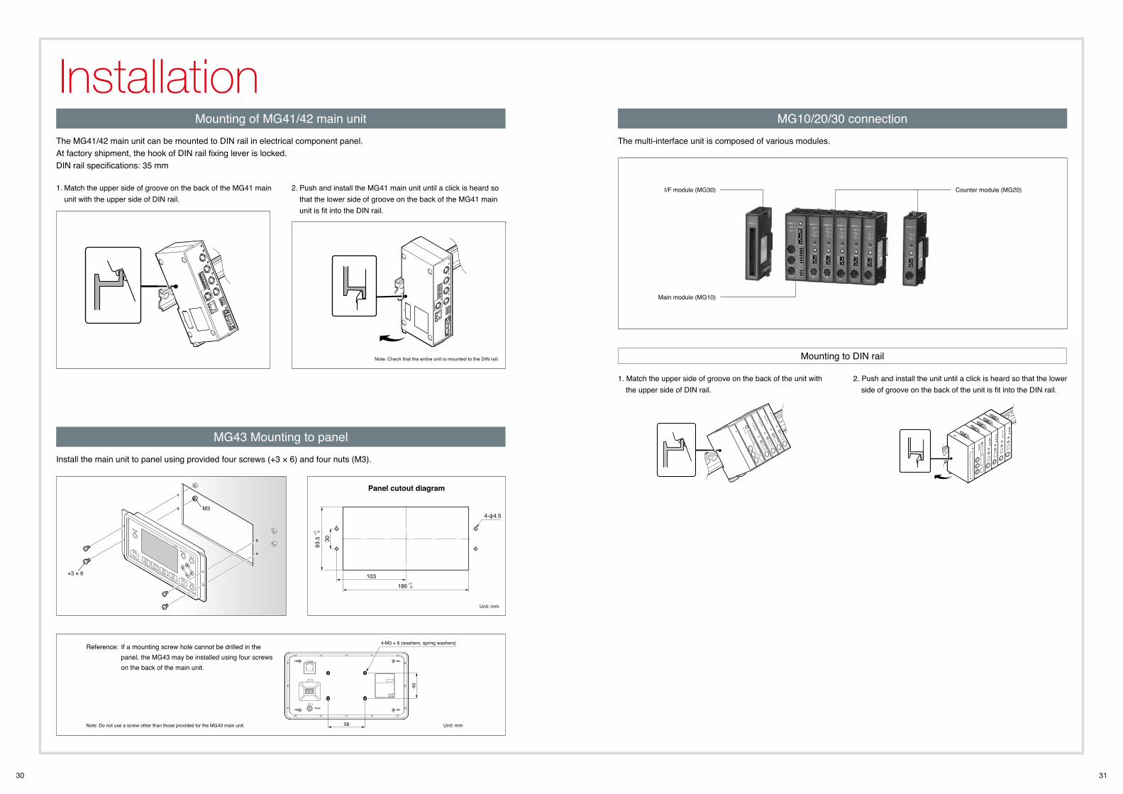
30 31
Installation
58
40
4-M3 × 6 (washers, spring washers)
4‐φ4.5
186
93.5 30
103+1
0
+1 0
Install the main unit to panel using provided four screws (+3 × 6) and four nuts (M3).
Mounting of MG41/42 main unit MG10/20/30 connection
MG43 Mounting to panel
The MG41/42 main unit can be mounted to DIN rail in electrical component panel. At factory shipment, the hook of DIN rail fixing lever is locked. DIN rail specifications: 35 mm
The multi-interface unit is composed of various modules.
1. Match the upper side of groove on the back of the MG41 main unit with the upper side of DIN rail.
Counter module (MG20)I/F module (MG30)
Main module (MG10)
2. Push and install the MG41 main unit until a click is heard so that the lower side of groove on the back of the MG41 main unit is fit into the DIN rail.
Panel cutout diagram
Note: Check that the entire unit is mounted to the DIN rail.
+3 × 6
M3
Note: Do not use a screw other than those provided for the MG43 main unit.
Reference: If a mounting screw hole cannot be drilled in the panel, the MG43 may be installed using four screws on the back of the main unit.
Unit: mm
Unit: mm
1. Match the upper side of groove on the back of the unit with the upper side of DIN rail.
2. Push and install the unit until a click is heard so that the lower side of groove on the back of the unit is fit into the DIN rail.
Mounting to DIN rail
32 33
LT30 Series 34
LT11A Series 35
LT10A Series 36
LY71 37
LY72 38
Counter
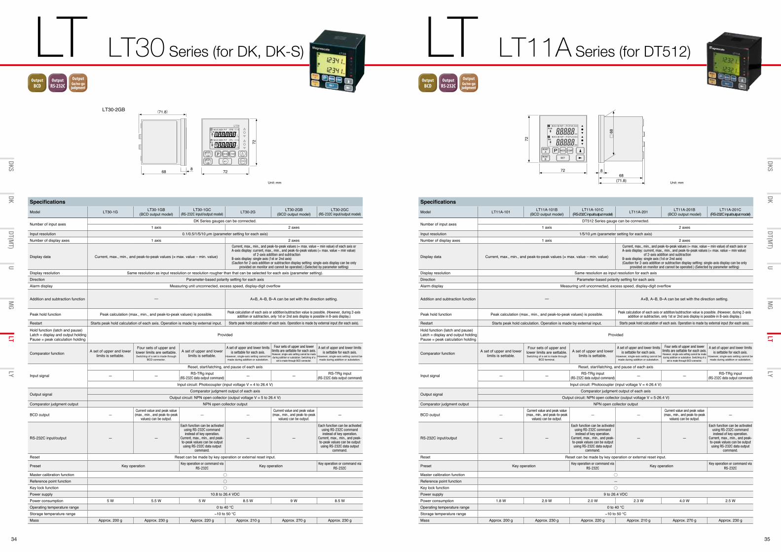
34 35
LT LT30 Series (for DK, DK-S) LT LT11A Series (for DT512)
DT(MT)
UMG
LTLY
DKSDK
DT(MT)
UMG
LTLY
DKSDK
Resolution0.1µm
Resolution0.5µm
Resolution1µm
Resolution5µm
Stemφ8
Stemφ20
Stemφ32
Stroke5mm
Stroke10mm
Stroke12mm
CommunicationCC-Link
OutputBCD
I/O出力 OutputRS-232C
OutputGo/no-gojudgment
CommunicationEthernet
Stroke32mm
Stroke60mm
Stroke25mm
Stroke30mm
Stroke50mm
Stroke100mm
Stroke110mm
Stroke155mm
Stroke205mm
OutputA/B phase
A/B出力MT接続時
Specifications
Model LT30-1G LT30-1GB(BCD output model)
LT30-1GC(RS-232C input/output model)
LT30-2G LT30-2GB(BCD output model)
LT30-2GC(RS-232C input/output model)
Number of input axesDK Series gauges can be connected.
1 axis 2 axesInput resolution 0.1/0.5/1/5/10 µm (parameter setting for each axis)Number of display axes 1 axis 2 axes
Display data Current, max., min., and peak-to-peak values (= max. value – min. value)
Current, max., min., and peak-to-peak values (= max. value – min value) of each axis or A-axis display: current, max., min., and peak-to-peak values (= max. value – min value) of 2-axis addition and subtraction B-axis display: single axis (1st or 2nd axis) (Caution for 2-axis addition or subtraction display setting: single-axis display can be only
provided on monitor and cannot be operated.) (Selected by parameter setting)
Display resolution Same resolution as input resolution or resolution rougher than that can be selected for each axis (parameter setting).Direction Parameter-based polarity setting for each axisAlarm display Measuring unit unconnected, excess speed, display-digit overflow
Addition and subtraction function ─ A+B, A–B, B–A can be set with the direction setting.
Peak hold function Peak calculation (max., min., and peak-to-peak values) is possible. Peak calculation of each axis or addition/subtraction value is possible. (However, during 2-axis addition or subtraction, only 1st or 2nd axis display is possible in B-axis display.)
Restart Starts peak hold calculation of each axis. Operation is made by external input. Starts peak hold calculation of each axis. Operation is made by external input (for each axis).
Hold function (latch and pause)Latch = display and output holding Pause = peak calculation holding
Provided
Comparator function A set of upper and lower limits is settable.
Four sets of upper and lower limits are settable. Switching of a set is made through
BCD connector.
A set of upper and lower limits is settable.
A set of upper and lower limits is settable for each axis.
However, single-axis setting cannot be made during addition or substation.
Four sets of upper and lower limits are settable for each axis.However, single-axis setting cannot be made during addition or substation. Switching of a
set is made through BCD connector.
A set of upper and lower limits is settable for each axis.
However, single-axis setting cannot be made during addition or substation.
Input signal
Reset, start/latching, and pause of each axis
— — RS-TRg input(RS-232C data output command)
— — RS-TRg input (RS-232C data output command)
Input circuit: Photocoupler (input voltage V = 4 to 26.4 V)
Output signalComparator judgment output of each axis
Output circuit: NPN open collector (output voltage V = 5 to 26.4 V) Comparator judgment output NPN open collector output
BCD output —Current value and peak value (max., min., and peak-to-peak
values) can be output.— —
Current value and peak value (max., min., and peak-to-peak
values) can be output.—
RS-232C input/output — —
Each function can be activated using RS-232C command instead of key operation.
Current, max., min., and peak-to-peak values can be output using RS-232C data output
command.
— —
Each function can be activated using RS-232C command instead of key operation.
Current, max., min., and peak-to-peak values can be output using RS-232C data output
command.
Reset Reset can be made by key operation or external reset input.
Preset Key operation Key operation or command via RS-232C
Key operation Key operation or command via RS-232C
Master calibration functionReference point functionKey lock function Power supply 10.8 to 26.4 VDCPower consumption 5 W 5.5 W 5 W 8.5 W 9 W 8.5 WOperating temperature range 0 to 40 °CStorage temperature range −10 to 50 °CMass Approx. 200 g Approx. 230 g Approx. 220 g Approx. 210 g Approx. 270 g Approx. 230 g
Specifications
Model LT11A-101 LT11A-101B(BCD output model)
LT11A-101C(RS-232C input/output model) LT11A-201 LT11A-201B
(BCD output model)LT11A-201C
(RS-232C input/output model)
Number of input axesDT512 Series gauge can be connected.
1 axis 2 axesInput resolution 1/5/10 µm (parameter setting for each axis)Number of display axes 1 axis 2 axes
Display data Current, max., min., and peak-to-peak values (= max. value – min. value)
Current, max., min., and peak-to-peak values (= max. value – min value) of each axis or A-axis display: current, max., min., and peak-to-peak values (= max. value – min value) of 2-axis addition and subtraction B-axis display: single axis (1st or 2nd axis) (Caution for 2-axis addition or subtraction display setting: single-axis display can be only
provided on monitor and cannot be operated.) (Selected by parameter setting)
Display resolution Same resolution as input resolution for each axisDirection Parameter-based polarity setting for each axisAlarm display Measuring unit unconnected, excess speed, display-digit overflow
Addition and subtraction function ─ A+B, A–B, B–A can be set with the direction setting.
Peak hold function Peak calculation (max., min., and peak-to-peak values) is possible. Peak calculation of each axis or addition/subtraction value is possible. (However, during 2-axis addition or subtraction, only 1st or 2nd axis display is possible in B-axis display.)
Restart Starts peak hold calculation. Operation is made by external input. Starts peak hold calculation of each axis. Operation is made by external input (for each axis).
Hold function (latch and pause)Latch = display and output holding Pause = peak calculation holding
Provided
Comparator function A set of upper and lower limits is settable.
Four sets of upper and lower limits are settable. Switching of a set is made through
BCD terminal.
A set of upper and lower limits is settable.
A set of upper and lower limits is settable for each axis.
However, single-axis setting cannot be made during addition or substation.
Four sets of upper and lower limits are settable for each axis.However, single-axis setting cannot be made during addition or substation. Switching of a
set is made through BCD connector.
A set of upper and lower limits is settable for each axis.
However, single-axis setting cannot be made during addition or substation.
Input signal
Reset, start/latching, and pause of each axis
— — RS-TRg input (RS-232C data output command)
— — RS-TRg input (RS-232C data output command)
Input circuit: Photocoupler (input voltage V = 4-26.4 V)
Output signalComparator judgment output of each axis
Output circuit: NPN open collector (output voltage V = 5-26.4 V) Comparator judgment output NPN open collector output
BCD output —Current value and peak value (max., min., and peak-to-peak
values) can be output.— —
Current value and peak value (max., min., and peak-to-peak
values) can be output.—
RS-232C input/output — —
Each function can be activated using RS-232C command instead of key operation.
Current, max., min., and peak-to-peak values can be output using RS-232C data output
command.
— —
Each function can be activated using RS-232C command instead of key operation.
Current, max., min., and peak-to-peak values can be output using RS-232C data output
command.
Reset Reset can be made by key operation or external reset input.
Preset Key operation Key operation or command via RS-232C
Key operation Key operation or command via RS-232C
Master calibration functionReference point function —Key lock functionPower supply 9 to 26.4 VDCPower consumption 1.8 W 2.9 W 2.0 W 2.3 W 4.0 W 2.5 WOperating temperature range 0 to 40 °CStorage temperature range −10 to 50 °CMass Approx. 200 g Approx. 230 g Approx. 220 g Approx. 210 g Approx. 270 g Approx. 230 g
72
72
682
682 (71.8)
68 8
72
72 868
(71.8)
68
LT30-2GB
Unit: mm Unit: mm
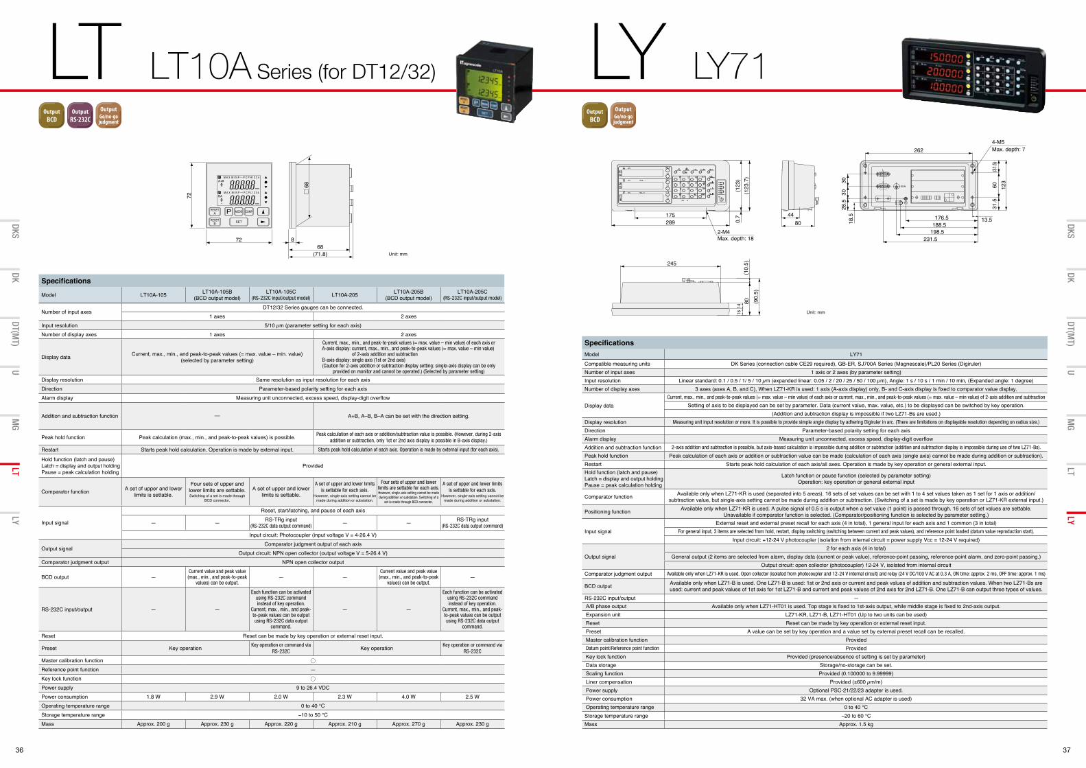
36 37
LT LT10A Series (for DT12/32) LY LY71
DT(MT)
UMG
LTLY
DKSDK
DT(MT)
UMG
LTLY
DKSDK
Resolution0.1µm
Resolution0.5µm
Resolution1µm
Resolution5µm
Stemφ8
Stemφ20
Stemφ32
Stroke5mm
Stroke10mm
Stroke12mm
CommunicationCC-Link
OutputBCD
I/O出力 OutputRS-232C
OutputGo/no-gojudgment
CommunicationEthernet
Stroke32mm
Stroke60mm
Stroke25mm
Stroke30mm
Stroke50mm
Stroke100mm
Stroke110mm
Stroke155mm
Stroke205mm
OutputA/B phase
A/B出力MT接続時
Specifications
Model LT10A-105 LT10A-105B(BCD output model)
LT10A-105C(RS-232C input/output model)
LT10A-205 LT10A-205B(BCD output model)
LT10A-205C(RS-232C input/output model)
Number of input axesDT12/32 Series gauges can be connected.
1 axes 2 axesInput resolution 5/10 µm (parameter setting for each axis)Number of display axes 1 axes 2 axes
Display data Current, max., min., and peak-to-peak values (= max. value – min. value) (selected by parameter setting)
Current, max., min., and peak-to-peak values (= max. value – min value) of each axis or A-axis display: current, max., min., and peak-to-peak values (= max. value – min value) of 2-axis addition and subtraction B-axis display: single axis (1st or 2nd axis) (Caution for 2-axis addition or subtraction display setting: single-axis display can be only
provided on monitor and cannot be operated.) (Selected by parameter setting)
Display resolution Same resolution as input resolution for each axisDirection Parameter-based polarity setting for each axisAlarm display Measuring unit unconnected, excess speed, display-digit overflow
Addition and subtraction function ─ A+B, A–B, B–A can be set with the direction setting.
Peak hold function Peak calculation (max., min., and peak-to-peak values) is possible. Peak calculation of each axis or addition/subtraction value is possible. (However, during 2-axis addition or subtraction, only 1st or 2nd axis display is possible in B-axis display.)
Restart Starts peak hold calculation. Operation is made by external input. Starts peak hold calculation of each axis. Operation is made by external input (for each axis).
Hold function (latch and pause)Latch = display and output holding Pause = peak calculation holding
Provided
Comparator function A set of upper and lower limits is settable.
Four sets of upper and lower limits are settable. Switching of a set is made through
BCD connector.
A set of upper and lower limits is settable.
A set of upper and lower limits is settable for each axis.
However, single-axis setting cannot be made during addition or substation.
Four sets of upper and lower limits are settable for each axis.However, single-axis setting cannot be made during addition or substation. Switching of a
set is made through BCD connector.
A set of upper and lower limits is settable for each axis.
However, single-axis setting cannot be made during addition or substation.
Input signal
Reset, start/latching, and pause of each axis
— — RS-TRg input (RS-232C data output command)
— — RS-TRg input (RS-232C data output command)
Input circuit: Photocoupler (input voltage V = 4-26.4 V)
Output signalComparator judgment output of each axis
Output circuit: NPN open collector (output voltage V = 5-26.4 V)Comparator judgment output NPN open collector output
BCD output —Current value and peak value (max., min., and peak-to-peak
values) can be output.— —
Current value and peak value (max., min., and peak-to-peak
values) can be output.—
RS-232C input/output — —
Each function can be activated using RS-232C command instead of key operation.
Current, max., min., and peak-to-peak values can be output using RS-232C data output
command.
— —
Each function can be activated using RS-232C command instead of key operation.
Current, max., min., and peak-to-peak values can be output using RS-232C data output
command.
Reset Reset can be made by key operation or external reset input.
Preset Key operation Key operation or command via RS-232C
Key operation Key operation or command via RS-232C
Master calibration functionReference point function —Key lock functionPower supply 9 to 26.4 VDCPower consumption 1.8 W 2.9 W 2.0 W 2.3 W 4.0 W 2.5 WOperating temperature range 0 to 40 °CStorage temperature range −10 to 50 °CMass Approx. 200 g Approx. 230 g Approx. 220 g Approx. 210 g Approx. 270 g Approx. 230 g
SpecificationsModel LY71Compatible measuring units DK Series (connection cable CE29 required), GB-ER, SJ700A Series (Magnescale)/PL20 Series (Digiruler)Number of input axes 1 axis or 2 axes (by parameter setting)Input resolution Linear standard: 0.1 / 0.5 / 1/ 5 / 10 µm (expanded linear: 0.05 / 2 / 20 / 25 / 50 / 100 µm), Angle: 1 s / 10 s / 1 min / 10 min, (Expanded angle: 1 degree)Number of display axes 3 axes (axes A, B, and C), When LZ71-KR is used: 1 axis (A-axis display) only, B- and C-axis display is fixed to comparator value display.
Display dataCurrent, max., min., and peak-to-peak values (= max. value – min value) of each axis or current, max., min., and peak-to-peak values (= max. value – min value) of 2-axis addition and subtraction
Setting of axis to be displayed can be set by parameter. Data (current value, max. value, etc.) to be displayed can be switched by key operation.(Addition and subtraction display is impossible if two LZ71-Bs are used.)
Display resolution Measuring unit input resolution or more. It is possible to provide simple angle display by adhering Digiruler in arc. (There are limitations on displayable resolution depending on radius size.)
Direction Parameter-based polarity setting for each axisAlarm display Measuring unit unconnected, excess speed, display-digit overflowAddition and subtraction function 2-axis addition and subtraction is possible, but axis-based calculation is impossible during addition or subtraction (addition and subtraction display is impossible during use of two LZ71-Bs).
Peak hold function Peak calculation of each axis or addition or subtraction value can be made (calculation of each axis (single axis) cannot be made during addition or subtraction).Restart Starts peak hold calculation of each axis/all axes. Operation is made by key operation or general external input.Hold function (latch and pause)Latch = display and output holding Pause = peak calculation holding
Latch function or pause function (selected by parameter setting) Operation: key operation or general external input
Comparator function Available only when LZ71-KR is used (separated into 5 areas). 16 sets of set values can be set with 1 to 4 set values taken as 1 set for 1 axis or addition/subtraction value, but single-axis setting cannot be made during addition or subtraction. (Switching of a set is made by key operation or LZ71-KR external input.)
Positioning function Available only when LZ71-KR is used. A pulse signal of 0.5 s is output when a set value (1 point) is passed through. 16 sets of set values are settable.Unavailable if comparator function is selected. (Comparator/positioning function is selected by parameter setting.)
Input signalExternal reset and external preset recall for each axis (4 in total), 1 general input for each axis and 1 common (3 in total)
For general input, 3 items are selected from hold, restart, display switching (switching between current and peak values), and reference point loaded (datum value reproduction start).
Input circuit: +12-24 V photocoupler (isolation from internal circuit = power supply Vcc = 12-24 V required)
Output signal2 for each axis (4 in total)
General output (2 items are selected from alarm, display data (current or peak value), reference-point passing, reference-point alarm, and zero-point passing.)Output circuit: open collector (photocoupler) 12-24 V, isolated from internal circuit
Comparator judgment output Available only when LZ71-KR is used. Open collector (isolated from photocoupler and 12-24 V internal circuit) and relay (24 V DC/100 V AC at 0.3 A, ON time: approx. 2 ms, OFF time: approx. 1 ms)
BCD output Available only when LZ71-B is used. One LZ71-B is used: 1st or 2nd axis or current and peak values of addition and subtraction values. When two LZ71-Bs are used: current and peak values of 1st axis for 1st LZ71-B and current and peak values of 2nd axis for 2nd LZ71-B. One LZ71-B can output three types of values.
RS-232C input/output —A/B phase output Available only when LZ71-HT01 is used. Top stage is fixed to 1st-axis output, while middle stage is fixed to 2nd-axis output.Expansion unit LZ71-KR, LZ71-B, LZ71-HT01 (Up to two units can be used)Reset Reset can be made by key operation or external reset input.Preset A value can be set by key operation and a value set by external preset recall can be recalled.Master calibration function ProvidedDatum point/Reference point function ProvidedKey lock function Provided (presence/absence of setting is set by parameter)Data storage Storage/no-storage can be set.Scaling function Provided (0.100000 to 9.99999)Liner compensation Provided (±600 µm/m)Power supply Optional PSC-21/22/23 adapter is used.Power consumption 32 VA max. (when optional AC adapter is used)Operating temperature range 0 to 40 °CStorage temperature range −20 to 60 °CMass Approx. 1.5 kg
72
72 868
(71.8)
68
4480
245
(90.
5)80
14
(10.
5)16
289175
(123
.7)
(123
)0.
7
2-M4Max. depth: 18
176.5188.5
198.5231.5
13.5
262
3028
.518
.530
123
60(3
1.5)
31.5
4-M5Max. depth: 7
Unit: mm
Unit: mm
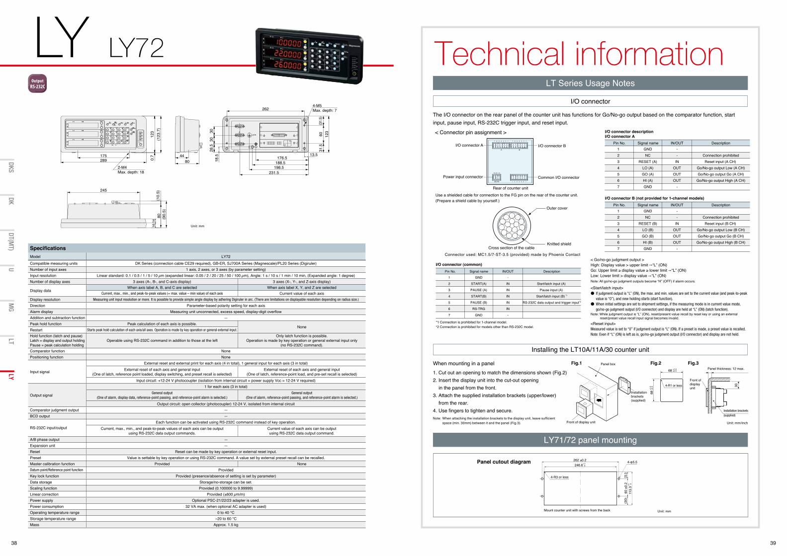
38 39
LY LY72 Technical information
DT(MT)
UMG
LTLY
DKSDK
SpecificationsModel LY72Compatible measuring units DK Series (connection cable CE29 required), GB-ER, SJ700A Series (Magnescale)/PL20 Series (Digiruler) Number of input axes 1 axis, 2 axes, or 3 axes (by parameter setting)Input resolution Linear standard: 0.1 / 0.5 / 1 / 5 / 10 µm (expanded linear: 0.05 / 2 / 20 / 25 / 50 / 100 µm), Angle: 1 s / 10 s / 1 min / 10 min, (Expanded angle: 1 degree)Number of display axes 3 axes (A-, B-, and C-axis display) 3 axes (X-, Y-, and Z-axis display)
Display dataWhen axis label A, B, and C are selected When axis label X, Y, and Z are selected
Current, max., min., and peak-to-peak values (= max. value – min value) of each axis Current value of each axisDisplay resolution Measuring unit input resolution or more. It is possible to provide simple angle display by adhering Digiruler in arc. (There are limitations on displayable resolution depending on radius size.)
Direction Parameter-based polarity setting for each axisAlarm display Measuring unit unconnected, excess speed, display-digit overflowAddition and subtraction function —Peak hold function Peak calculation of each axis is possible.
NoneRestart Starts peak hold calculation of each axis/all axes. Operation is made by key operation or general external input.
Hold function (latch and pause)Latch = display and output holding Pause = peak calculation holding
Operable using RS-232C command in addition to those at the leftOnly latch function is possible.
Operation is made by key operation or general external input only(no RS-232C command).
Comparator function NonePositioning function None
Input signal
External reset and external print for each axis (4 in total), 1 general input for each axis (3 in total)External reset of each axis and general input
(One of latch, reference point loaded, display switching, and preset recall is selected)External reset of each axis and general input
(One of latch, reference-point load, and pre-set recall is selected)Input circuit: +12-24 V photocoupler (isolation from internal circuit = power supply Vcc = 12-24 V required)
Output signal
1 for each axis (3 in total)General output
(One of alarm, display data, reference-point passing, and reference-point alarm is selected.)General output
(One of alarm, reference-point passing, and reference-point alarm is selected.)
Output circuit: open collector (photocoupler) 12-24 V, isolated from internal circuitComparator judgment output —BCD output —
RS-232C input/outputEach function can be activated using RS-232C command instead of key operation.
Current, max., min., and peak-to-peak values of each axis can be outputusing RS-232C data output commands.
Current value of each axis can be outputusing RS-232C data output command.
A/B phase output —Expansion unit —Reset Reset can be made by key operation or external reset input.Preset Value is settable by key operation or using RS-232C command. A value set by external preset recall can be recalled.Master calibration function Provided NoneDatum point/Reference point function ProvidedKey lock function Provided (presence/absence of setting is set by parameter)Data storage Storage/no-storage can be set.Scaling function Provided (0.100000 to 9.99999)Linear correction Provided (±600 µm/m)Power supply Optional PSC-21/22/23 adapter is used.Power consumption 32 VA max. (when optional AC adapter is used)Operating temperature range 0 to 40 °CStorage temperature range −20 to 60 °CMass Approx. 1.5 kg
68 +1.0+0.4
68+1
.0+0
.4 30
Resolution0.1µm
Resolution0.5µm
Resolution1µm
Resolution5µm
Stemφ8
Stemφ20
Stemφ32
Stroke5mm
Stroke10mm
Stroke12mm
CommunicationCC-Link
OutputBCD
I/O出力 OutputRS-232C
OutputGo/no-gojudgment
CommunicationEthernet
Stroke32mm
Stroke60mm
Stroke25mm
Stroke30mm
Stroke50mm
Stroke100mm
Stroke110mm
Stroke155mm
Stroke205mm
OutputA/B phase
A/B出力MT接続時
245
(90.
5)80
1416
(10.
5)
2-M4Max. depth: 18
4-M5Max. depth: 7
175289
4480
176.5188.5
198.5231.5
13.5
262
(123
.7)
123
0.7
3028
.518
.530
123
6031
.5(31
.5)
Unit: mm
Installation brackets (supplied)
Installation brackets (supplied)
4-R1 or less
Panel thickness: 12 max.
Front of display unit
When mounting in a panel1. Cut out an opening to match the dimensions shown (Fig.2)2. Insert the display unit into the cut-out opening
in the panel from the front.3. Attach the supplied installation brackets (upper/lower)
from the rear.4. Use fingers to tighten and secure.
LY71/72 panel mounting
Panel cutout diagram
Fig.1 Fig.2 Fig.3
Unit: mm
Unit: mm/inch
LT Series Usage Notes
I/O connector
Installing the LT10A/11A/30 counter unit
The I/O connector on the rear panel of the counter unit has functions for Go/No-go output based on the comparator function, start input, pause input, RS-232C trigger input, and reset input.
< Connector pin assignment >
1234567
GNDNC
RESET (A)LO (A)GO (A)HI (A)GND
Pin No.--
INOUTOUTOUT
-
Signal name IN/OUT
Connection prohibitedReset input (A CH)
Go/No-go output Low (A CH)Go/No-go output Go (A CH)
Go/No-go output High (A CH)
Description
Use a shielded cable for connection to the FG pin on the rear of the counter unit.(Prepare a shield cable by yourself.)
I/O connector description I/O connector A
1234567
GNDNC
RESET (B)LO (B)GO (B)HI (B)GND
Pin No.--
INOUTOUTOUT
-
Signal name IN/OUT
Connection prohibitedReset input (B CH)
Go/No-go output Low (B CH)Go/No-go output Go (B CH)
Go/No-go output High (B CH)
Description
I/O connector B (not provided for 1-channel models)
Rear of counter unit
7 6 5 4 3 2 1 7 6 5 4 3 2 1
1 2 3 4 5 6 7
A B
FG �V 0V
DC IN
I/O connector BI/O connector A
Power input connector Common I/O connector
Cross section of the cable
Outer cover
Knitted shield
Connector used: MC1.5/7-ST-3.5 (provided) made by Phoenix Contact
If judgment output is “L” (ON), the max. and min. values are set to the current value (and peak-to-peak value is “0”), and new holding starts (start function).When initial settings are set to shipment settings, if the measuring mode is in current value mode, go/no-go judgment output (I/O connector) and display are held at “L” (ON) (latch function).
<Reset input> Measured value is set to “0” if judgment output is “L” (ON). If a preset is made, a preset value is recalled. Note: Even if “L” (ON) is left as is, go/no-go judgment output (I/O connector) and display are not held.
1
2
3
4
5
6
7
GND
START(A)
PAUSE (A)
START(B)
PAUSE (B)
RS-TRG
GND
Pin No.
-
IN
IN
IN
IN
IN
-
Signal name IN/OUT
Start/latch input (A)
Pause input (A)
Start/latch input (B) *1
RS-232C data output and trigger input*2
Description
I/O connector (common)
*1 Connection is prohibited for 1-channel model. *2 Connection is prohibited for models other than RS-232C model.
< Go/no-go judgment output > High: Display value > upper limit “L” (ON) Go: Upper limit ≥ display value ≥ lower limit “L” (ON) Low: Lower limit > display value “L” (ON)Note: All go/no-go judgment outputs become “H” (OFF) if alarm occurs.
Note: While judgment output is “L” (ON), reset/present value recall by reset key or using an external reset/preset value recall input signal becomes invalid.
<Start/latch input>
Front of display unit
Panel box
4-R3 or less
Mount counter unit with screws from the back
262 ±0.2
60 ±
0.2
4-φ5.5
(30)
23.3
113.
3+1 0
246.6+1 0
Note: When attaching the installation brackets to the display unit, leave sufficient space (min. 30mm) between it and the panel (Fig.3).
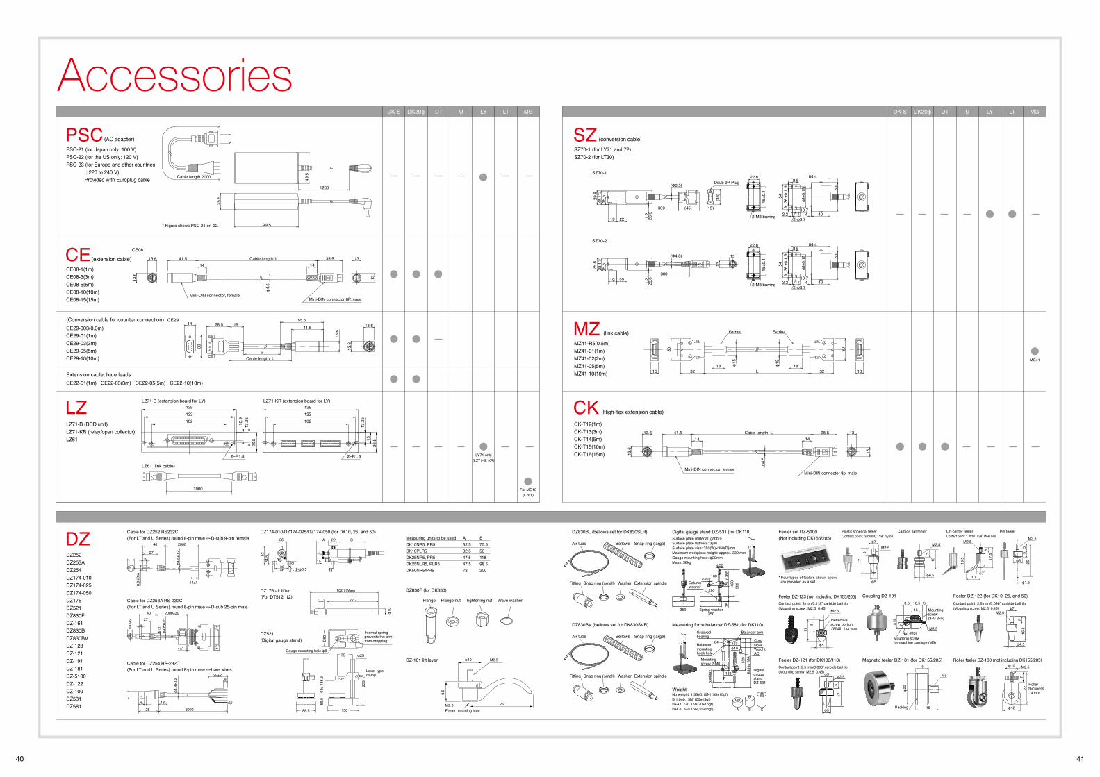
40 41
Accessories
Mini-DIN connector, female
φ4.
5
Mini-DIN connector 8p, male
13
13
13.6
13.6
41.514
35.514
Cable length: L
Ferrite Ferrite
30
10 32 L 32
30
18 18φ15
φ15
10
22.8
±0.1
45
2-M3 burring
8.5
±0.1
546
10.72.2 17
99
±0.1
36
40
54
84.4
4
63
2-φ3.7
(Φ4.8)
300
1.222
15.5
19
-0+0.2
28.1
28.6
29.8
13
13
Measuring units to be used DK10NR5, PR5DK10PLR5DK25NR5, PR5DK25NLR5, PLR5DK50NR5/PR5
A32.532.547.547.572
B75.55611898.5200
PSCPSC-21 (for Japan only: 100 V) PSC-22 (for the US only: 120 V) PSC-23 (for Europe and other countries : 220 to 240 V) Provided with Europlug cable
(AC adapter) (conversion cable)
(extension cable)
Extension cable, bare leads
CE08-1(1m)CE08-3(3m)CE08-5(5m)CE08-10(10m)CE08-15(15m)
Cable length 2000
99.5
25.5
49.5
1200
Mini-DIN connector, female
φ4.
5
Mini-DIN connector 8P, male
13
13
13.6
13.6
41.514
35.514
Cable length: LCE
(High-flex extension cable)
LZ71-B (BCD unit) LZ71-KR (relay/open collector)LZ61
LZ
40 2000±3027
6
4±1
φ12
φ4.
8±02
φ8.
95
200028
136
525±2
φ4.
8±0.
2
26
3646 2-φ5.5
15934.553
11
B22A
DZ174-010/DZ174-025/DZ174-050 (for DK10, 25, and 50)
M2.5
Feeler mounting holeM2.5
8.5
φ10
26
DZ-161 lift lever
40 2000
276
φ4.
8±0.
2
8.95
DIA
14±1
102.7(Max)
77.7
φ10
DZ176 air lifter (For DT512, 12)
Flange Flange nut Tightening nut Wave washer
DZ830F (for DK830)
DZ830BL (bellows set for DK830SLR)
DZ252DZ253ADZ254DZ174-010DZ174-025DZ174-050DZ176DZ521DZ830FDZ-161DZ830BDZ830BVDZ-123DZ-121DZ-191DZ-181DZ-5100DZ-122DZ-100DZ531DZ581
DZ
88.5 150
75 φ25
59.5
0 to
135
.5
233
�80
Lever-typeclamp
Gauge mounting hole φ8
Internal spring prevents the arm from dropping.
DZ521(Digital gauge stand)
DK-S DK20φ DT U LY LT MG
CKCK-T12(1m)CK-T13(3m)CK-T14(5m)CK-T15(10m)CK-T16(15m)
SZ70-1 (for LY71 and 72) SZ70-2 (for LT30)
SZ
(link cable)
MZ41-R5(0.5m)MZ41-01(1m)MZ41-02(2m)MZ41-05(5m)MZ41-10(10m)
MZCE29-003(0.3m)CE29-01(1m)CE29-03(3m)CE29-05(5m)CE29-10(10m)
CE22-01(1m) CE22-03(3m) CE22-05(5m) CE22-10(10m)
(Conversion cable for counter connection)
LY71 only(LZ71-B, KR)
For MG10(LZ61)
MG41
CE08
Cable for DZ252 RS232C (For LT and U Series) round 8-pin male D-sub 9-pin female
Cable for DZ253A RS-232C (For LT and U Series) round 8-pin male D-sub 25-pin male
Cable for DZ254 RS-232C (For LT and U Series) round 8-pin male bare wires
DZ830BV (bellows set for DK830SVR)
Air tube
Fitting Snap ring (small) Extension spindle
Bellows Snap ring (large)
Washer
Air tube
Fitting Snap ring (small) Extension spindle
Bellows Snap ring (large)
Washer
1000
LZ61 (link cable)
LZ71-B (extension board for LY) LZ71-KR (extension board for LY)
Feeler DZ-122 (for DK10, 25, and 50)
φ7
φ4.5
516
.8
M2.5
Contact point: 2.5 mm/0.098” carbide ball tip (Mounting screw: M2.5 0.45)
Feeler DZ-123 (not including DK155/205)
φ5
511
M2.5
Ineffective screw portion: Width 1 or less
Contact point: 3 mm/0.118” carbide ball tip (Mounting screw: M2.5 0.45)
Coupling DZ-1918.5 16.5 5
15
φ18
Mounting screw (3-M 3×5)
Nut (M5)M2.5
Mounting screw for machine carriage (M5)
Feeler DZ-121 (for DK100/110)
M2.5φ9
17
φ5
5
Contact point: 2.5 mm/0.098” carbide ball tip (Mounting screw: M2.5 0.45)
Roller feeler DZ-100 (not including DK155/205)
Roller thickness: 4 mm
φ12
φ10
722
M2.5
Magnetic feeler DZ-181 (for DK155/205)9
16
φ22
M5
Packing
φ7
φ5
M2.5
517
Plastic spherical feelerContact point: 3 mm/0.118” nylon
φ6.5
513
M2.5
Carbide flat feeler
φ710
19.3
517
.5
M2.5
Off-center feelerContact point: 1 mm/0.039” steel ball
Pin feeler
φ1.5
255
5
φ6
M2.5
* Four types of feelers shown above are provided as a set.
Feeler set DZ-5100(Not including DK155/205)
* Figure shows PSC-21 or -22.
Measuring force balancer DZ-581 (for DK110)
64
Grooved bearing
Cord
Balancer arm
153φ10
Mounting screw 2-M6 52
0
330M
ax.
633
to 6
98
Balancer mounting hook hole
Digital gauge stand DZ-531
HookWeightAC
135
Digital gauge stand DZ-531 (for DK110)
160φ20
290
Columnwasher
Spring washer350
350
φ50
50025
to 3
5575
420
WeightNo weight: 1.55±0.15N(155±15gf)B:1.0±0.15N(100±15gf)B+A:0.7±0.15N(70±15gf)B+C:0.3±0.15N(30±15gf) A B C
Surface plate material: gabbroSurface plate flatness: 3μm Surface plate size: 350(W)×350(D)mm Maximum workpiece height: approx. 330 mm Gauge mounting hole: φ20mm Mass: 38kg
SZ70-1
SZ70-2
Dsub 9P Plug
29.8
28.6
28.1
+0.2 -0
19
15.5
22 1.2
300 (45) (15)
(33)
22.8
±0.1
45
2-M3 burring
8.5
±0.1
546
10.72.2 17
99
±0.1
36
40
54
84.4
4
63
2-φ3.7
(Φ6.5)
DK-S DK20φ DT U LY LT MG
1928.555.5
41.5
13.6
14
30
13.6
13.6
CE29
2Cable length: L
129122102
26.5
13.2
510
.9
2−R1.8 2−R1.8
13.2
515
26.5
129122102
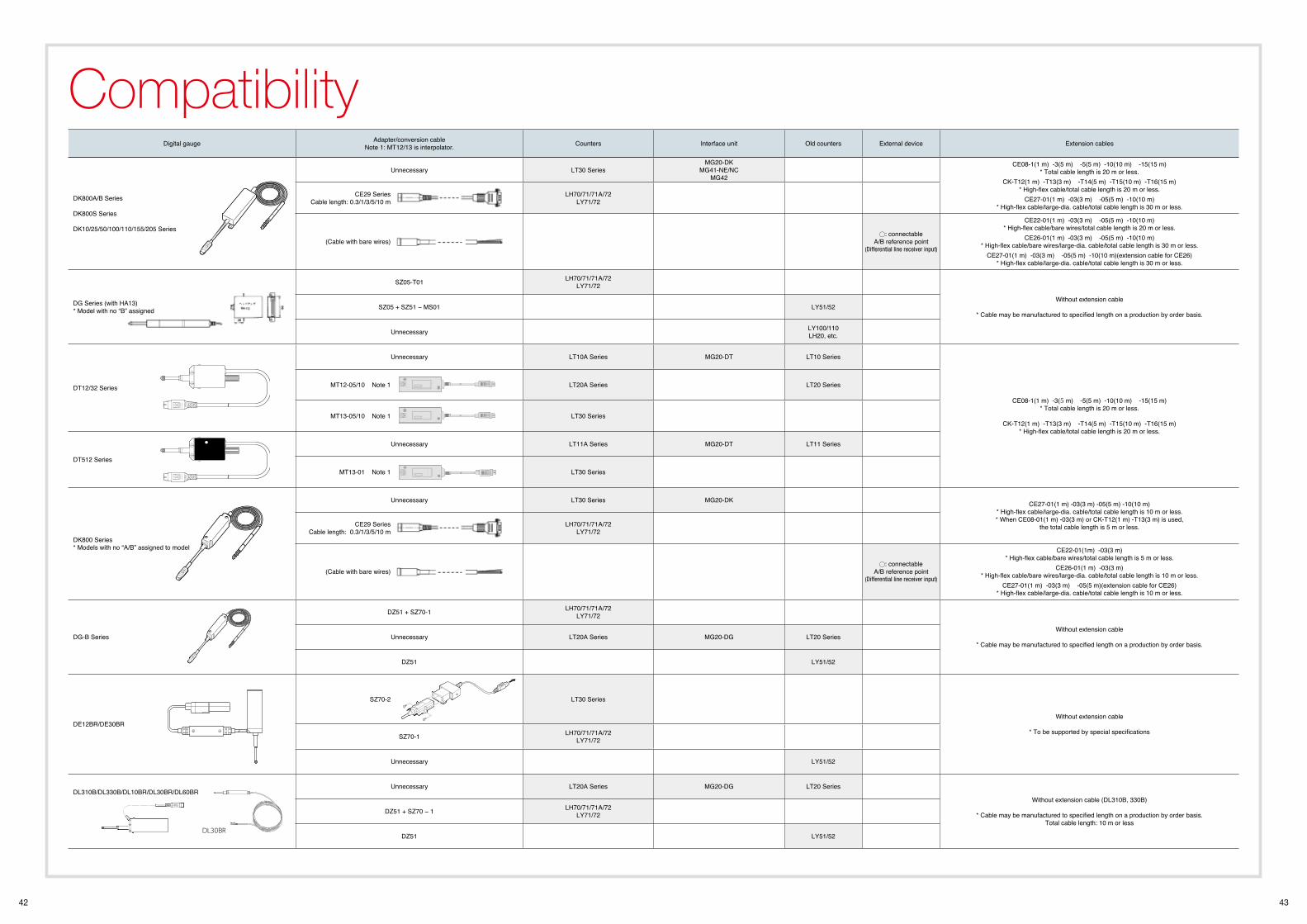
42 43
CompatibilityDigital gauge Adapter/conversion cable
Note 1: MT12/13 is interpolator. Counters Interface unit Old counters External device Extension cables
DK800A/B Series DK800S Series
DK10/25/50/100/110/155/205 Series
Unnecessary LT30 SeriesMG20-DK
MG41-NE/NCMG42
CE08-1(1 m) -3(5 m) -5(5 m) -10(10 m) -15(15 m) * Total cable length is 20 m or less.
CK-T12(1 m) -T13(3 m) -T14(5 m) -T15(10 m) -T16(15 m)* High-flex cable/total cable length is 20 m or less.
CE27-01(1 m) -03(3 m) -05(5 m) -10(10 m)* High-flex cable/large-dia. cable/total cable length is 30 m or less.
CE29 Series Cable length: 0.3/1/3/5/10 m
LH70/71/71A/72LY71/72
(Cable with bare wires): connectable
A/B reference point (Differential line receiver input)
CE22-01(1 m) -03(3 m) -05(5 m) -10(10 m)* High-flex cable/bare wires/total cable length is 20 m or less.
CE26-01(1 m) -03(3 m) -05(5 m) -10(10 m)* High-flex cable/bare wires/large-dia. cable/total cable length is 30 m or less.
CE27-01(1 m) -03(3 m) -05(5 m) -10(10 m)(extension cable for CE26)* High-flex cable/large-dia. cable/total cable length is 30 m or less.
DG Series (with HA13)* Model with no “B” assigned
SZ05-T01 LH70/71/71A/72LY71/72
Without extension cable
* Cable may be manufactured to specified length on a production by order basis.SZ05 + SZ51 − MS01 LY51/52
Unnecessary LY100/110LH20, etc.
DT12/32 Series
Unnecessary LT10A Series MG20-DT LT10 Series
CE08-1(1 m) -3(5 m) -5(5 m) -10(10 m) -15(15 m)* Total cable length is 20 m or less.
CK-T12(1 m) -T13(3 m) -T14(5 m) -T15(10 m) -T16(15 m)* High-flex cable/total cable length is 20 m or less.
MT12-05/10 Note 1 LT20A Series LT20 Series
MT13-05/10 Note 1 LT30 Series
DT512 Series
Unnecessary LT11A Series MG20-DT LT11 Series
MT13-01 Note 1 LT30 Series
DK800 Series * Models with no “A/B” assigned to model
Unnecessary LT30 Series MG20-DK CE27-01(1 m) -03(3 m) -05(5 m) -10(10 m)* High-flex cable/large-dia. cable/total cable length is 10 m or less.* When CE08-01(1 m) -03(3 m) or CK-T12(1 m) -T13(3 m) is used,
the total cable length is 5 m or less.CE29 Series Cable length: 0.3/1/3/5/10 m
LH70/71/71A/72LY71/72
(Cable with bare wires): connectable
A/B reference point (Differential line receiver input)
CE22-01(1m) -03(3 m)* High-flex cable/bare wires/total cable length is 5 m or less.
CE26-01(1 m) -03(3 m)* High-flex cable/bare wires/large-dia. cable/total cable length is 10 m or less.
CE27-01(1 m) -03(3 m) -05(5 m)(extension cable for CE26)* High-flex cable/large-dia. cable/total cable length is 10 m or less.
DG-B Series
DZ51 + SZ70-1 LH70/71/71A/72LY71/72
Without extension cable
* Cable may be manufactured to specified length on a production by order basis.Unnecessary LT20A Series MG20-DG LT20 Series
DZ51 LY51/52
DE12BR/DE30BR
SZ70-2 LT30 Series
Without extension cable
* To be supported by special specificationsSZ70-1 LH70/71/71A/72
LY71/72
Unnecessary LY51/52
DL310B/DL330B/DL10BR/DL30BR/DL60BRUnnecessary LT20A Series MG20-DG LT20 Series
Without extension cable (DL310B, 330B)
* Cable may be manufactured to specified length on a production by order basis. Total cable length: 10 m or less
DZ51 + SZ70 − 1 LH70/71/71A/72LY71/72
DZ51 LY51/52DL30BR
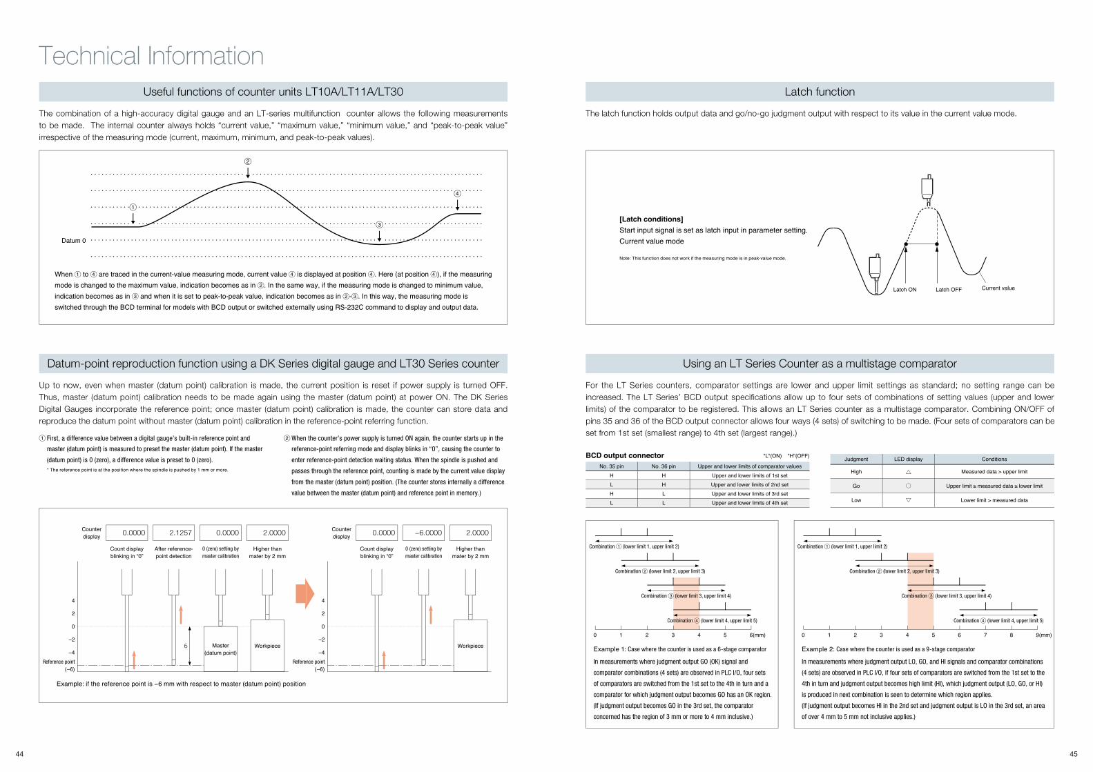
44 45
Technical Information
Current valueLatch OFFLatch ON
BCD output connector "L"(ON) "H"(OFF)
No. 35 pin No. 36 pin Upper and lower limits of comparator valuesH H Upper and lower limits of 1st set L H Upper and lower limits of 2nd set H L Upper and lower limits of 3rd set L L Upper and lower limits of 4th set
Judgment LED display Conditions
High Measured data > upper limit
Go Upper limit ≥ measured data ≥ lower limit
Low Lower limit > measured data
The combination of a high-accuracy digital gauge and an LT-series multifunction counter allows the following measurements to be made. The internal counter always holds “current value,” “maximum value,” “minimum value,” and “peak-to-peak value” irrespective of the measuring mode (current, maximum, minimum, and peak-to-peak values).
Example: if the reference point is −6 mm with respect to master (datum point) position
Example 1: Case where the counter is used as a 6-stage comparator Example 2: Case where the counter is used as a 9-stage comparatorMaster
(datum point)6
4
2
0
−2
−4Reference point
(−6)
4
2
0
−2
−4Reference point
(−6)
Workpiece Workpiece
Up to now, even when master (datum point) calibration is made, the current position is reset if power supply is turned OFF. Thus, master (datum point) calibration needs to be made again using the master (datum point) at power ON. The DK Series Digital Gauges incorporate the reference point; once master (datum point) calibration is made, the counter can store data and reproduce the datum point without master (datum point) calibration in the reference-point referring function.
When to are traced in the current-value measuring mode, current value is displayed at position . Here (at position ), if the measuring mode is changed to the maximum value, indication becomes as in . In the same way, if the measuring mode is changed to minimum value, indication becomes as in and when it is set to peak-to-peak value, indication becomes as in - . In this way, the measuring mode is switched through the BCD terminal for models with BCD output or switched externally using RS-232C command to display and output data.
The latch function holds output data and go/no-go judgment output with respect to its value in the current value mode.
[Latch conditions]Start input signal is set as latch input in parameter setting. Current value mode
For the LT Series counters, comparator settings are lower and upper limit settings as standard; no setting range can be increased. The LT Series’ BCD output specifications allow up to four sets of combinations of setting values (upper and lower limits) of the comparator to be registered. This allows an LT Series counter as a multistage comparator. Combining ON/OFF of pins 35 and 36 of the BCD output connector allows four ways (4 sets) of switching to be made. (Four sets of comparators can be set from 1st set (smallest range) to 4th set (largest range).)
Datum-point reproduction function using a DK Series digital gauge and LT30 Series counter
Latch function
Using an LT Series Counter as a multistage comparator
Useful functions of counter units LT10A/LT11A/LT30
First, a difference value between a digital gauge’s built-in reference point and
master (datum point) is measured to preset the master (datum point). If the master
(datum point) is 0 (zero), a difference value is preset to 0 (zero). * The reference point is at the position where the spindle is pushed by 1 mm or more.
In measurements where judgment output GO (OK) signal and
comparator combinations (4 sets) are observed in PLC I/O, four sets
of comparators are switched from the 1st set to the 4th in turn and a
comparator for which judgment output becomes GO has an OK region.
(If judgment output becomes GO in the 3rd set, the comparator
concerned has the region of 3 mm or more to 4 mm inclusive.)
Combination (lower limit 1, upper limit 2) Combination (lower limit 1, upper limit 2)
Combination (lower limit 2, upper limit 3) Combination (lower limit 2, upper limit 3)
Combination (lower limit 3, upper limit 4) Combination (lower limit 3, upper limit 4)
Combination (lower limit 4, upper limit 5) Combination (lower limit 4, upper limit 5)
0 1 2 3 4 5 6(mm) 0 1 2 3 4 5 6 7 8 9(mm)
In measurements where judgment output LO, GO, and HI signals and comparator combinations
(4 sets) are observed in PLC I/O, if four sets of comparators are switched from the 1st set to the
4th in turn and judgment output becomes high limit (HI), which judgment output (LO, GO, or HI)
is produced in next combination is seen to determine which region applies.
(If judgment output becomes HI in the 2nd set and judgment output is LO in the 3rd set, an area
of over 4 mm to 5 mm not inclusive applies.)
When the counter’s power supply is turned ON again, the counter starts up in the
reference-point referring mode and display blinks in “0”, causing the counter to
enter reference-point detection waiting status. When the spindle is pushed and
passes through the reference point, counting is made by the current value display
from the master (datum point) position. (The counter stores internally a difference
value between the master (datum point) and reference point in memory.)
Counter display 0.0000 2.1257 0.0000 2.0000
Count display blinking in “0”
After reference-point detection
0 (zero) setting by master calibration
Higher than mater by 2 mm
Counter display 0.0000 −6.0000 2.0000
Count display blinking in “0”
0 (zero) setting by master calibration
Higher than mater by 2 mm
Note: This function does not work if the measuring mode is in peak-value mode.
Datum 0
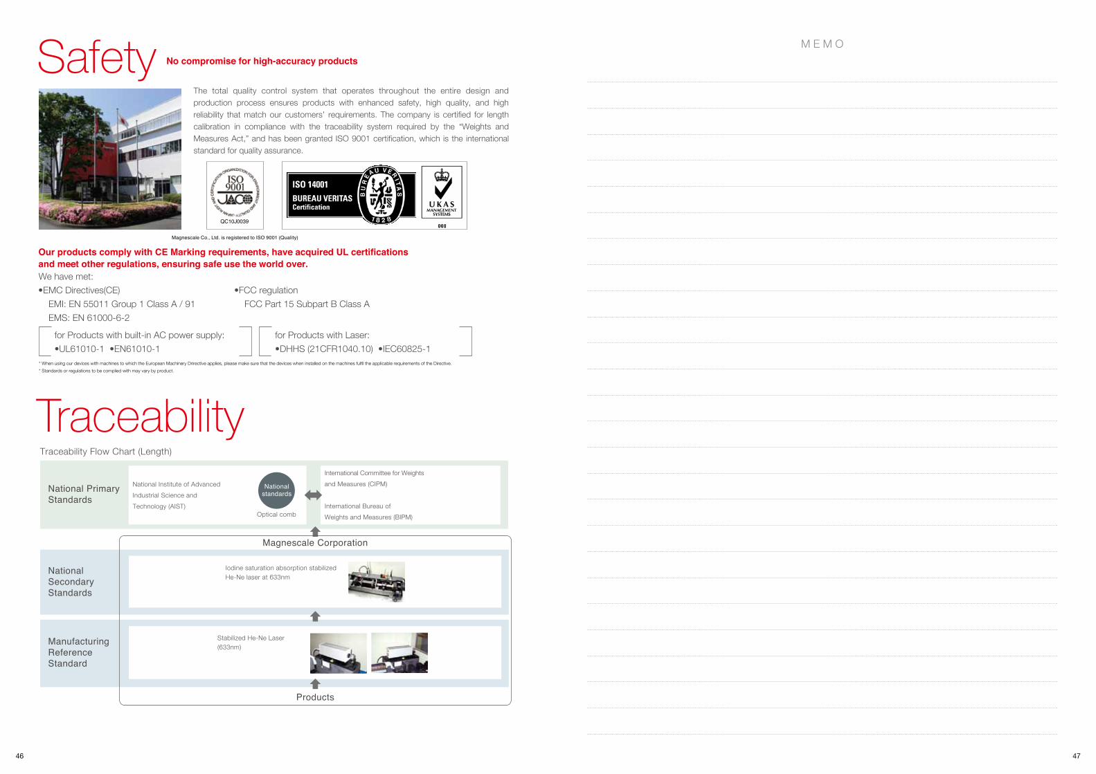
46 47
TraceabilityTraceability Flow Chart (Length)
National Primary Standards
National Institute of Advanced Industrial Science and Technology (AIST)
International Committee for Weightsand Measures (CIPM)
International Bureau of Weights and Measures (BIPM)
NationalSecondaryStandards
Iodine saturation absorption stabilized He-Ne laser at 633nm
Magnescale Corporation
Products
Stabilized He-Ne Laser (633nm)
Nationalstandards
Optical comb
Manufacturing Reference Standard
Safety
We have met:
Our products comply with CE Marking requirements, have acquired UL certifications and meet other regulations, ensuring safe use the world over.
* When using our devices with machines to which the European Machinery Drirective applies, please make sure that the devices when installed on the machines fulfil the applicable requirements of the Directive.* Standards or regulations to be complied with may vary by product.
•EMC Directives(CE) EMI: EN 55011 Group 1 Class A / 91 EMS: EN 61000-6-2
•FCC regulation FCC Part 15 Subpart B Class A
for Products with built-in AC power supply:•UL61010-1 •EN61010-1
for Products with Laser:•DHHS (21CFR1040.10) •IEC60825-1
The total quality control system that operates throughout the entire design and production process ensures products with enhanced safety, high quality, and high reliability that match our customers’ requirements. The company is certified for length calibration in compliance with the traceability system required by the “Weights and Measures Act,” and has been granted ISO 9001 certification, which is the international standard for quality assurance.
No compromise for high-accuracy products
QC10J0039
Magnescale Co., Ltd. is registered to ISO 9001 (Quality)
M E M O


![Digital Gauge General Catalog - magnescale.com · Digital Gauge General Catalog ... [Shape] No symbol : straight L : right angle V : pneumatic push ... 60mm Stroke 25mm Stroke 30mm](https://img.dokumen.tips/doc/110x75/5ad9ce1e7f8b9a6d7e8bd65c/digital-gauge-general-catalog-gauge-general-catalog-shape-no-symbol-straight.jpg)