Embed Size (px)
Citation preview

Research ArticleDigital Fuzzy Current Controlled Light-Emitting DiodeDriver with Power Factor Correction
A. S. Veerendra ,1,2 A. A. Shah ,1 M. SubbaRao ,3 and M. R. Mohamed 2
1Key Laboratory of Low-Grade Energy Utilization Technologies and Systems, MOE, Chongqing University, Chongqing 400030, China2College of Engineering, Universiti Malaysia Pahang, Gambang, 26300 Kuantan, Pahang, Malaysia3Department of Electrical and Electronics Engineering, Vignan’s Foundation for Science, Technology and Research, Vadlamudi,Andhra Pradesh, India
Correspondence should be addressed to A. A. Shah; [email protected] and M. R. Mohamed; [email protected]
Received 17 December 2020; Revised 1 February 2021; Accepted 4 March 2021; Published 15 March 2021
Academic Editor: Francesco Riganti Fulginei
Copyright © 2021 A. S. Veerendra et al. This is an open access article distributed under the Creative Commons Attribution License,which permits unrestricted use, distribution, and reproduction in any medium, provided the original work is properly cited.
This paper presents the design and development of a fuzzy peak current controlled (FPCC) single-stage single-phase nonisolatedAC/DC high-power factor LED drive. The proposed controller includes a fuzzy logic controller (FLC) in the loop voltage and apeak current controller in the loop current for an integrated nonisolated LED driver to attain a high-power factor (PF). Theproposed control avoids complexities related to nonlinearities of the converter. The control action is initially derived from agroup of rules written in accordance with experience and intuitive reasoning. The proposed technique is realized using a DSPprocessor (TI-TMS320F2812), which is capable of executing a high number of instructions in one cycle. A 70W, 350mA LEDdriver operating with an input of 90V-230V, 50Hz was designed and implemented using MATLAB/Simulink. The results ofthe driver are in accordance with international regulations. The steady-state and transient responses are validated experimentally.
1. Introduction
An LED is a semiconductor unit that emits visible light whena current is passed through it. Lamps have good efficiency,are mercury free, and are long lasting [1, 2]. An LED providescontrol over light distribution with lenses or small reflectorsand affords adaptability in the design of lighting apparatuses[3]. A block diagram of driver circuit is shown in Figure 1. Inthe case of a sinusoidal supply voltage, the driver must draw asinusoidal current from the mains. To achieve this, an activefilter is used along with a switched-mode power supply in oneof two designs, namely, two-stage [4–7] and single-stage [8–12] power factor correction (PFC) topologies.
The two-stage power factor correction approach utilizesan input current shaping converter ahead of the DC/DC con-verter. Both of the converters are controlled individually toaccomplish PFC and fast voltage regulation. This techniqueis known for its superior performance, such as high-power fac-tor and low input current harmonics, which is achieved at thecost of additional circuitry (including control circuitry). This
might not be justified for low-power applications. Subse-quently, a one-stage design was proposed by using the conceptof integration [13, 14]. In [15], an integrated buck-boost driverwith classical controllers is examined for LED applications. Itconsists of a single control switch operated in buck and boostmodes. The main drawback of the topology is a high value ofstorage capacitance and a voltage ripple. To minimize thecapacitance, Soares et al. discussed a slope compensation tech-nique in [16]. However, the ripple content is still increased inthe voltage and current responses.
A driver may suffer damage if the current is higher thanthe rated current. In order to restrict the current, a closed-loop system control is important. Severe working conditionsin terms of temperature and current density certainly influ-ence the efficiency of LEDs [17]. The LED is used not onlyfor lighting but also for several other applications such ascomputer or scoreboard displays. For such applications, theLED needs a driver that can control the voltage for all ofthe lamps. A fast settling time is also necessary for a score-board, due to high lighting motion from one LED to another
HindawiInternational Journal of PhotoenergyVolume 2021, Article ID 6618284, 10 pageshttps://doi.org/10.1155/2021/6618284

within 5 to 100ms. The color changing requires rapidresponses in the current value and a stable voltage; therefore,proper control of the current and voltage distributions isrequired.
In recent years, there has been an increasing interest incontrol strategies to enhance the dynamic behavior ofAC/DC converters. Classical (PI, sliding mode) and intelli-gent (fuzzy, neurofuzzy) control techniques are used in theliterature to improve the performance of drivers. In [18–21], the authors considered converters possessing linearcharacteristics, but this strategy is not appropriate for someoperating conditions. Moreover, there exists uncertaintydue to source variations and load changes. Fuzzy logic con-trol (FLC) is advantageous in this regard because it canaccommodate parameter variations in the system and cantherefore incorporate modeling uncertainty, neglected com-ponents, and nonlinearities [22–24]. Knowledge-based FLCattempts to code human knowledge, experience, and acumento be able to make informed choices about the performanceof the system. Knowledge-based FLC is a fuzzy rule base withsuitable choices to control the activity of the plant underexamination without human intervention [25–29]. In [30],the authors were able to achieve a PF of 0.98 and 13% THDusing a digital fuzzy controller.
All passive components constituting the converters canbe described by linear characteristics. This assumption isobviously not valid under all operational conditions, particu-larly since the inductance coefficients vary with the current.Moreover, there exists modeling uncertainty in the presenceof input voltage fluctuations, load changes, and values ofthe component coefficients. Hence, in this work, we proposeand develop a FLC in-the-loop voltage and fixed frequencypeak current controller in the loop current for an integratednonisolated LED driver. Unlike conventional controllers, afuzzy peak current controller (FPCC) is used. To maintainperformance under coil magnetic saturation and modeluncertainty, FLC is selected because it can deal with theaforementioned uncertainty and variations, as well asneglected elements and nonlinearities. In this work, we con-sider source variations and load changes. The proposed con-troller attains a high-power factor (PF) with a low %THD,comparing favourably with conventional methods. Further-more, the voltage loop driver feeds a regulated voltage tothe LED panel. The DSP is a better option to realize the pro-posed FPCC due to its fast execution. Moreover, the driver islow cost, so that the controller and processor are affordable.
The objectives of this work are as follows:
(1) To design and develop an intelligent controller thatcan act effectively during source variations and loadchanges
(2) To achieve a high-power factor with a driver circuitduring source and load variations in order to complywith international standards
(3) To attain a low %THD for any source and load varia-tions in order to comply with international standards
2. Analysis of LED Driver
The integrated nonisolated LED driver is depicted in Figure 2,and the corresponding parameters are explained as follows.
2.1. Mains Current and Power. The current through L1 dur-ing ð0 –DTSÞ is the line current (is), where D is duty cycleand Ts is switching time period. The value of the mains cur-rent averaged at line frequency can be obtained using
isð Þ = 1Ts
12 ispeakDTs =
D2Vs
2L1 f ssin wLtð Þ, ð1Þ
where ispeak is the instantaneous peak current, f s is the switching
frequency, and Vs is the peak line voltage. From Equation (1),the line current is sinusoidal in shape, and subsequently, thepower factor (PF) is unity by filtering electromagnetic interfer-ence (EMI) with a filter. The mean input power (Pg) is given by
Pg =12Vs ispeak
� �= D2Vs
4L1 f s: ð2Þ
2.2. Load and Bus Voltages. The load voltage (Vo) for the drivercan be obtained by equating the supply and load powers. Theload power is given as Po = V2
o/R, where R is the static resis-tance of the LED, given by
R = VLEDILED
=Vγ + RγILED
ILED=
Vγ
ILED+ Rγ, ð3Þ
in which Rγ and Vγ are the resistance and voltage of theLED, respectively. By assuming 100% efficiency, Vo =DVs/2ffiffiffik
pand k = L1 f s/R. The bus voltage can be calculated from
the voltage ratio as follows:
VB =1 −DD
Vo =1 −Dð ÞVg
2ffiffiffiffiK
p : ð4Þ
To ensure a high PF, the converter must be operated in dis-continuous conduction mode (DCM) and the critical limit forthe duty cycle (Dlm) can be obtained from the voltage transfor-mation via Dlm = ð1 +Vs/VBÞ−1.2.3. Reactive Components. The value of L1 can be obtainedfrom L1 =D2V2
s /ð4Pof sÞ by assuming there are no losses.The bus capacitance for a known peak-to-peak voltage ripple is
C1 =D2
8VBπL1 f s f LΔVBLF
V2s : ð5Þ
ACsource
Dioderectifier
Integrated nonisolatedconverter
LEDload
Gate signals
Figure 1: Block diagram of the driver.
2 International Journal of Photoenergy

ACsource
Load
D1 D3
D5 iD5 D6 D7
D8
V1
R1C2
C1
L2
S
iSiL1
iD6 iD7
D2 D4
L1
++
Figure 2: Circuit diagram of the integrated nonisolated LED driver.
ACsource
Fuzzycontroller
Compensatingramp
Load
D1 D3
D5 iD5 D6 D7
D8
V1
R1C2
C1
L2
S
iSiL1
ISW1 Ve
ΔVe
iD6 iD7
D2 D4
L1
++
Comparatorand pulsegenerator
(a)
Fuzzifier Defuzzifier Controller outputsController inputs Inference engine
Fuzzy
Crisp
Fuzzy
Crisp
Fuzzy logic controller
Knowledge base
Data base Rule base
(b)
Figure 3: (a) Block diagram of the FPCC LED driver with compensating ramp; (b) FPCC components.
3International Journal of Photoenergy

The inductance and capacitance L2 and C2 are obtainedfrom
L2 =DVB
0:5ΔILOHF f s,
C2 =DVO
ΔVOHFf s,
ð6Þ
where ΔILOHF is the current ripple and ΔVOHFis the output
voltage ripple.
3. Proposed Fuzzy Controlled LED Driver
The driver is nonlinear and time varying from a control sys-tem point of view:
(1) The driver circuit possesses nonlinear characteristicsowing to the voltage and power of the LEDs. At anominal working voltage, the characteristics experi-ence a large gradient. This means that a small changein voltage can lead to a significant change of currentand therefore to a considerable change in the emitted
light. Moreover, when devices are connected to non-linear loads, there could be several nonlinear rela-tions between the system variables
(2) The system is time varying because the parameters ofthe system change with the temperature and mag-netic saturation
A fuzzy approach offers the possibility to model a nonlin-ear system using knowledge of many non-well-defined rela-tions among the variables of the system and allows for thedesign of a controller that adapts itself to several workingconditions. Thus, fuzzy logic seems a suitable solution bothto model and to control drives. The circuit diagram of thedriver with a compensation ramp is shown in Figure 3(a).The driver is controlled with a fuzzy voltage loop by a Mam-dani type fuzzy inference system, and the outer current loopconsists of a peak current control with slope compensation.
The error between the reference voltage and converteroutput voltage and its variation are the inputs to the FLC(see Equations (7) and (8)). The FPCC and its componentsare shown in Figure 3(b). The output voltage is tracked andcompared to the reference signal, and the generated errorVe and change in error Vce are given as inputs to the FLCto obtain a suitable signal to the current controller loop. Inthe current controller loop, three signals are used in orderto generate the pulses to the switches: the inductor signal,the FLC signal, and the compensating ramp signal. Althoughnot considered here, parameter and model uncertainties canbe incorporated directly as fuzzy numbers in the fuzzy settheory.
The FLC consists of the following components: a fuzzifierconverts crisp data into fuzzy data; a knowledge base con-tains a data base and a fuzzy rule set; an inference engine
Start
No YesDiscrete design
Design continuouscontroller
Convert to discretecontroller
Determine ranges oncontroller inputs
Choose inputmembership function
Initialize rules andoutput singletons
Tune fuzzycontroller usingtrial and error
Finish
Figure 4: Process flow chart.
Table 1: Rule base.
ENB NM NS ZE PS PM PB
CE
NB NB NB NB NB NM NS ZE
NM NB NB NB NM NS ZE PS
NS NB NB NM NS ZE PS PM
ZE NB NM NS ZE PS PM PB
PS NM NS ZE PS PM PB PB
PM NS ZE PS PM PB PB PB
PB ZE PS PM PB PB PB PB
Table 2: Design parameters.
Component Value
Switching frequency (f s) 50 kHz
Inductance1 (L1) 2.5mH
Capacitance1 (C1) 80 μF
Inductance2 (L2) 9mH
Capacitance2 (C2) 40 μF
Load resistance (R) 570Ω
Equivalent voltage of LED load (Vγ) 170V
4 International Journal of Photoenergy
Discrete1e-06 s.
Out1
Out2
Out1
Out2
Out3
Out1
Out2
Out3
Out4
Out5Conn1
Conn3
IL
VmQ
Conn2
Filter components
Clock To workspace
Simout
Diode rectifierIntegrated converter
Fuzzy controller
Conn3
Conn3
Conn2Scope6
Scope2
Scope3
Scope1
Subsystem1
Scope
Scope5
Scope8
Scope4
Conn1In1
Conn1
Conn1
Conn2Conn4
Conn4
Conn2
AC
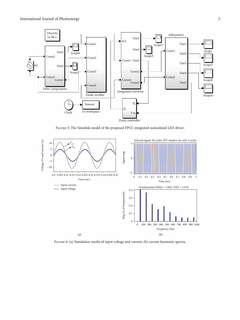
Figure 5: The Simulink model of the proposed FPCC integrated nonisolated LED driver.
−10
−5
0
5
10
0.2 0.21 0.22 0.23 0.24 0.25
Vol
tage
(V) a
nd cu
rren
t (A
)
Time (sec)0.2450.2350.2250.2150.205
VinIin
Input currentInput voltage
(a)
−5
0
5
0 0.2 0.4 0.6 0.8 1
Sign
al m
ag.
Time (sec)
Fundamental (50Hz) = 5.002, THD = 3.51%
Selected signal: 50 cycles. FFT window (in red): 2 cycles
0.90.70.50.30.1
0
0.4
0 100 300 400 600 800 1000
Mag
(% o
f fun
dam
enta
l)
Frequency (Hz)900700500200
0.3
0.2
0.1
(b)
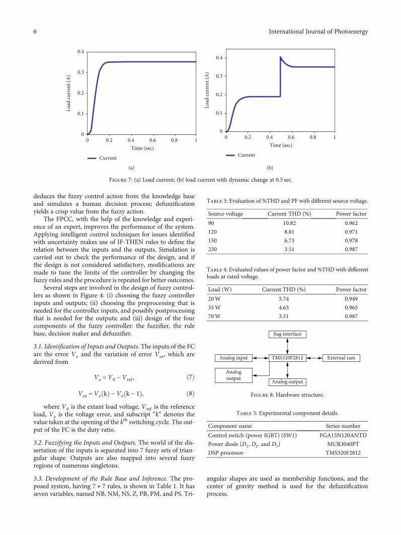
Figure 6: (a) Simulation results of input voltage and current; (b) current harmonic spectra.
5International Journal of Photoenergy
deduces the fuzzy control action from the knowledge baseand simulates a human decision process; defuzzificationyields a crisp value from the fuzzy action.
The FPCC, with the help of the knowledge and experi-ence of an expert, improves the performance of the system.Applying intelligent control techniques for issues identifiedwith uncertainty makes use of IF-THEN rules to define therelation between the inputs and the outputs. Simulation iscarried out to check the performance of the design, and ifthe design is not considered satisfactory, modifications aremade to tune the limits of the controller by changing thefuzzy rules and the procedure is repeated for better outcomes.
Several steps are involved in the design of fuzzy control-lers as shown in Figure 4: (i) choosing the fuzzy controllerinputs and outputs; (ii) choosing the preprocessing that isneeded for the controller inputs, and possibly postprocessingthat is needed for the outputs; and (iii) design of the fourcomponents of the fuzzy controller: the fuzzifier, the rulebase, decision maker and defuzzifier.
3.1. Identification of Inputs and Outputs. The inputs of the FCare the error Ve and the variation of error Vce, which arederived from
Ve =V0 −V ref , ð7Þ
Vce = Ve kð Þ −Ve k − 1ð Þ, ð8Þwhere V0 is the extant load voltage, V ref is the reference
load, Ve is the voltage error, and subscript “k” denotes thevalue taken at the opening of the kth switching cycle. The out-put of the FC is the duty ratio.
3.2. Fuzzifying the Inputs and Outputs. The world of the dis-sertation of the inputs is separated into 7 fuzzy sets of trian-gular shape. Outputs are also mapped into several fuzzyregions of numerous singletons.
3.3. Development of the Rule Base and Inference. The pro-posed system, having 7 ∗ 7 rules, is shown in Table 1. It hasseven variables, named NB, NM, NS, Z, PB, PM, and PS. Tri-
angular shapes are used as membership functions, and thecenter of gravity method is used for the defuzzificationprocess.
0
0.1
0.2
0.3
0.4
0 0.2 0.4 0.6 0.8 1
Load
curr
ent (
A)
Time (sec)
Current
(a)
0
0.1
0.2
0.3
0.4
0 0.2 0.4 0.6 0.8 1
Load
curr
ent (
A)
Time (sec)
Current
(b)
Figure 7: (a) Load current; (b) load current with dynamic change at 0.5 sec.
Table 3: Evaluation of %THD and PF with different source voltage.
Source voltage Current THD (%) Power factor
90 10.82 0.962
120 8.81 0.971
150 6.73 0.978
230 3.51 0.987
Table 4: Evaluated values of power factor and %THD with differentloads at rated voltage.
Load (W) Current THD (%) Power factor
20W 5.74 0.949
35W 4.63 0.965
70W 3.51 0.987
Jtag interface
Analog input
Analog output
Analogoutput
TMS320F2812 External ram
Figure 8: Hardware structure.
Table 5: Experimental component details.
Component name Series number
Control switch (power IGBT) (SW1) FGA15N120ANTD
Power diode (D1, D2, and D3) MUR3040PT
DSP processor TMS320F2812
6 International Journal of Photoenergy

4. Design Parameters
The driver circuit was built in the laboratory and tested witha universal input (90V-230V) range. The driver wasdesigned to provide a power of 70W, with a rated lamp cur-rent of 350mA. The remaining component values are shownin Table 2.
5. Results and Discussion
5.1. Simulation Results. The proposed fuzzy peak currentcontrolled integrated nonisolated LED driver was developedin the MATLAB/Simulink software package. Figure 5 showsthe simulation model, in which a diode rectifier convertsthe AC source into DC, which is fed to the integrated con-verter. The output of the integrated converter is fed to theLED panel.
In order to control the driver unit, a proposed control ispresented in a feedback loop. Figure 6(a) shows the simula-tion results of the input voltage of a current waveform ratedat a voltage of 230V and at full load (70W). In the simula-tion, the waveform voltage magnitude is scaled to 10V bymultiplying with the factor 0.0307. This result shows thatthe input current is in-phase with voltage and current wave-form following a sinusoidal shape. The respective currentharmonic spectrum is also shown in Figure 6(b), which dem-onstrates that the harmonic content presented in the currentwave is below the international specifications (IEC-61000-3-2). The PF and percentage THD at this load are found to be0.987 and 3.51%, respectively. Figure 7(a) is the output cur-rent of the driver, which is maintained at 350mA. To evalu-ate the dynamic performance of the controller, a change ofload was made at 0.5 sec as shown in Figure 7(b), with a step-wise change in load from 175mA to 350mA (at 0.5 sec). Animproved dynamic response is observed.
From Table 3, the performance of the converter is signif-icantly improved with the universal input (90-230V). TheTHD improves from 10.82% to 3.51%. The PF of the driverin the entire range is found to be above 0.96.
It is observed from Table 4 that the power factor is higherat full load conditions and the corresponding THD is lower(0.987 and 3.51% at 70W).
5.2. Experimental Results. An experimental setup was imple-mented to validate the simulation results. Microcontrollersbased on FLCs for power converters were implemented, butdue to the high sampling frequency, control DSPs wereinstead used. The proposed controller was implementedusing a TMS320F2812 DSP, which is a 32-bit processor oper-ating at 150MHz. The digital converter contains the recom-pense network, fault amp, slant recompense, and PWMgenerator, which work in a discrete time domain. In thispaper, we used a Texas Instruments TMS320F2812 DSP pro-cessor. The duty is to initially set to 100% but tripped usingthe cycle-by-cycle trip feature of the processor. The yieldvoltage of the converter is connected to a resistive “inspectingdivider” arranged such that it is associated with DAC. Thevoltage is tested and changed over to advanced esteem. A dig-ital reference (REF) is subtracted from the digital value, andthe error value is used as an input to the digital controller.This represents the error amplifier and compensation net-work of the analog equivalent. The yield of the controller isincreased by an additional term K , which scales the yield ofthe controller to computerized esteem well-suited for usewith the D/A Converter (DAC). The general hardware struc-ture is shown in Figure 8. The output of the converter is sam-pled by an A/D converter, which gives the digital value to thefuzzy controller. The controller processes the data to producea PWM signal to the control switch SW1 of the converter.
The line voltage and current waveforms, load current andvoltage waveforms, and current harmonic content wereobserved. The experimental component details are listed inTable 5. Figure 9(a) shows the experimental setup of the pro-posed FPCC integrated nonisolated LED driver with a con-troller, while Figure 9(b) is a detailed picture of the controller.
The supply current was in-phase with a supply voltage of230V (V in: 300V/div; Iin: 0.5A/div). The correspondingmeasured PF is 0.973, and %THD is 5.67%. The respectiveharmonic spectra are shown in the left of Figure 10(a), while
(a) (b)
Figure 9: (a) Laboratory hardware; (b) converter close up.
7International Journal of Photoenergy
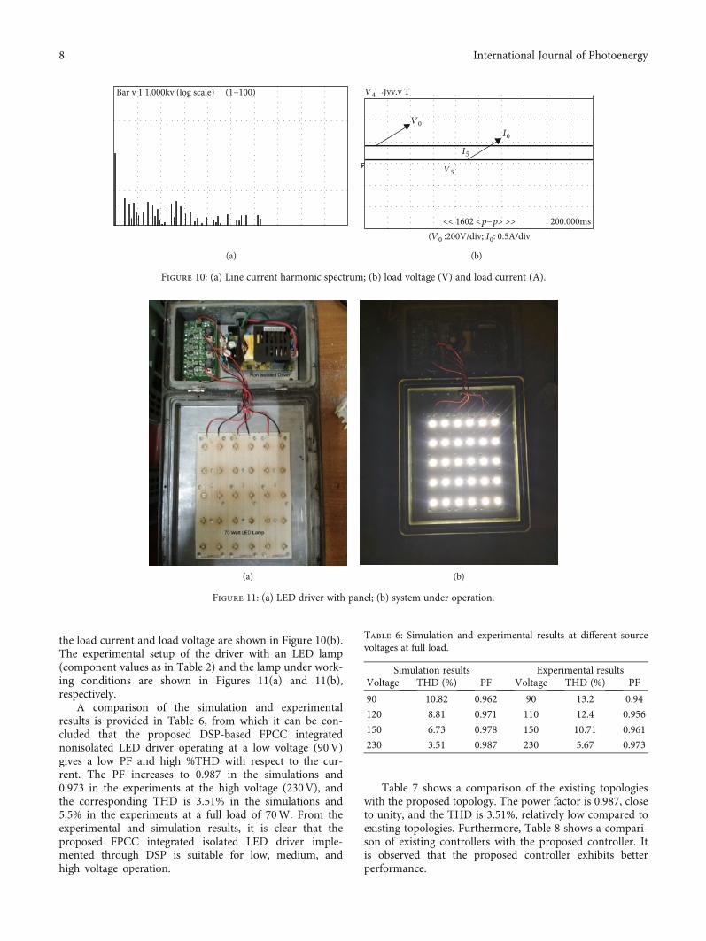
the load current and load voltage are shown in Figure 10(b).The experimental setup of the driver with an LED lamp(component values as in Table 2) and the lamp under work-ing conditions are shown in Figures 11(a) and 11(b),respectively.
A comparison of the simulation and experimentalresults is provided in Table 6, from which it can be con-cluded that the proposed DSP-based FPCC integratednonisolated LED driver operating at a low voltage (90V)gives a low PF and high %THD with respect to the cur-rent. The PF increases to 0.987 in the simulations and0.973 in the experiments at the high voltage (230V), andthe corresponding THD is 3.51% in the simulations and5.5% in the experiments at a full load of 70W. From theexperimental and simulation results, it is clear that theproposed FPCC integrated isolated LED driver imple-mented through DSP is suitable for low, medium, andhigh voltage operation.
Table 7 shows a comparison of the existing topologieswith the proposed topology. The power factor is 0.987, closeto unity, and the THD is 3.51%, relatively low compared toexisting topologies. Furthermore, Table 8 shows a compari-son of existing controllers with the proposed controller. Itis observed that the proposed controller exhibits betterperformance.
(a) (b)
Figure 11: (a) LED driver with panel; (b) system under operation.
Table 6: Simulation and experimental results at different sourcevoltages at full load.
Simulation results Experimental resultsVoltage THD (%) PF Voltage THD (%) PF
90 10.82 0.962 90 13.2 0.94
120 8.81 0.971 110 12.4 0.956
150 6.73 0.978 150 10.71 0.961
230 3.51 0.987 230 5.67 0.973
Bar v 1 1.000kv (log scale) (1−100)
(a)
V4
V0
V5
I0
I5
.Jvv.v T
<< 1602 <p−p> >>(V0 :200V/div; I0: 0.5A/div
200.000ms
(b)
Figure 10: (a) Line current harmonic spectrum; (b) load voltage (V) and load current (A).
8 International Journal of Photoenergy

6. Conclusions
This paper presents a fuzzy integrated nonisolated LEDdriver designed to achieve a high-power factor (PF). It con-sists of fuzzy control in a voltage loop and peak current con-trol in a current loop. The voltage loop regulates the outputvoltage, and the current loop improves the power factor.Fuzzy logic is used in a feedback path and linear program-ming rule to govern the magnitude of the reference currentduring this proposed technique in order to regulate theswitch’s duty cycle for shaping the input current. The pro-posed method avoids complexity related to nonlinearity ofswitching converters and is ready to react quickly to loadchanges, so controller processing leads to better dynamicperformance. The experimental results at steady state showedthat the proposed control strategy is capable of producing apower factor value of almost unity under a wide range of sup-ply voltage and load power conditions. The experimentalresults show that the PF of the driver is 0.973 and the%THD is 5.67% at full load, and therefore, the efficiency ofthe driver is 86.5%, which meets international regulations(IEC-61000-3-2).
Abbreviations
PF: Power factorLED: Light-emitting diodeFLC: Fuzzy logic controllerDSP: Digital signal processorFPCC: Fuzzy peak current controlledTHD: Total harmonic distortion.
Data Availability
Data is available upon request.
Conflicts of Interest
The authors declare that they have no conflicts of interest.
Acknowledgments
This project was partially supported by the National KeyResearch and Development Program of China (Grant No.2017YFB0701700). This work was supported by the NationalUniversity Malaysia Pahang (UMP) (Grant No. PGRS200321),andMr. A.S. Veerendra is working as a research scholar underUMP’s Doctoral Research Scheme (DRS).
References
[1] Y.Wang, J. Alonso, and X. Ruan, “A review of LED drivers andrelated technologies,” IEEE Transactions on Industrial Elec-tronics, vol. 64, no. 7, pp. 5754–5765, 2017.
[2] W.-j. Cha, Y.-W. Cho, and J.-M. Kwon, “Single power-conversion LED backlight driving system with high power fac-tor control,” Journal of Display Technology, vol. 10, no. 5,pp. 407–413, 2014.
[3] T.-P. Sun and C.-H. Wang, “Specially designed driver circuitsto stabilize LED light output without a photodetector,” IEEETransactions on Power Electronics, vol. 27, no. 9, pp. 4140–4152, 2012.
[4] Y. Wang, Y. Guan, D. Xu, and W. Wang, “A CLCL resonantDC/DC converter for two-stage LED driver system,” IEEETransactions on Industrial Electronics, vol. 63, pp. 2883–2891, 2015.
[5] P. Athalye, M. Harris, and G. Negley, “A two-stage LED driverfor high-performance high-voltage LED fixtures,” in 2012Twenty-Seventh Annual IEEE Applied Power Electronics Con-ference and Exposition (APEC), pp. 2385–2391, Orlando, FL,USA, February 2012.
[6] X. Xie, M. Ye, Y. Cai, and J. Wu, “An opto coupler less two-stage high power factor LED driver,” in 2011 Twenty-SixthAnnual IEEE Applied Power Electronics Conference and Expo-sition (APEC), pp. 2078–2083, Fort Worth, TX, USA, March2011.
[7] W. Lin, H. Chen, and S. Ke, “Research on a single-stage fly-back/boost LED driver with lower output ripple,” in 2016 IEEE2nd Annual Southern Power Electronics Conference (SPEC),,pp. 1–5, Auckland, New Zealand, December 2016.
Table 7: Comparisons between the existing single-stage LED drivers and the proposed driver.
LED driverSpecification parameter
Power factor (PF) Total harmonic distortion (%THD)
Integrated buck-flyback converter [18] 0.970 27.5%
Single-stage LED driver [10] 0.99 7.9%
Single-stage LED streetlight driver with soft-switching and interleaved PFC [12] 0.97 5%
Proposed 0.987 3.51%
Table 8: Comparisons of existing controllers and the proposed controller.
ControllersSpecification parameter
Power factor (PF) Total harmonic distortion (%THD)
Fixed-frequency constant-current control [18] 0.970 27.5%
QR valley-switching scheme [21] 0.93 23%
Conventional current control [15] 0.96 28%
Proposed 0.987 3.51
9International Journal of Photoenergy

[8] Y. Guo, S. Li, A. T. L. Lee, S.-C. Tan, C. K. Lee, and S. Y. R. Hui,“Single-stage AC/DC single-inductor multiple-output LEDdrivers,” IEEE Transactions on Power Electronics, vol. 31,pp. 5837–5850, 2015.
[9] J. W. Fan, J. P.-W. Chow, W.-T. Chan et al., “Modeling andexperimental assessment of the EMI characteristics of switch-ing converters with power semiconductor filters,” IEEE Trans-actions on Power Electronics, vol. 35, no. 3, pp. 2519–2533,2020.
[10] S. Mangkalajan, C. Ekkaravarodome, K. Jirasereeamornkul,P. Thounthong, K. Higuchi, and M. K. Kazimierczuk, “Asingle-stage LED driver based on ZCDS class-E current-driven rectifier as a PFC for street-lighting applications,” IEEETransactions on Power Electronics, vol. 33, no. 10, pp. 8710–8727, 2018.
[11] Y. Wang, X. Deng, Y. Wang, and D. Xu, “Single-Stage bridge-less LED driver based on a CLCL resonant converter,” IEEETransactions on Industry Applications, vol. 54, no. 2,pp. 1832–1841, 2018.
[12] C.-A. Cheng, C.-H. Chang, H.-L. Cheng, E.-C. Chang, T.-Y. Chung, and M.-T. Chang, “A single-stage LED streetlightdriver with soft-switching and interleaved PFC features,” Elec-tronics, vol. 8, no. 8, p. 911, 2019.
[13] G. G. Pereira, M. A. Dalla Costa, J. M. Alonso, M. F. de Melo,and C. H. Barriquello, “LED driver based on input currentshaper without electrolytic capacitor,” IEEE Transactions onIndustrial Electronics, vol. 64, no. 6, pp. 4520–4529, 2017.
[14] J. M. Alonso, D. Gacio, A. J. Calleja et al., “Reducing storagecapacitance in off-line LED power supplies by using integratedconverters,” in 2012 IEEE Industry Applications SocietyAnnual Meeting, pp. 1–8, Las Vegas, NV, USA, October 2012.
[15] J. Alonso, J. Vina, D. Gacio, G. Martinez, and R. O. Sanchez,“Analysis and design of the integrated double buck-boost con-verter as a high-power-factor driver for power-LED lamps,”IEEE Transactions on Industrial Electronics, vol. 59, no. 4,pp. 1689–1697, 2012.
[16] G. M. Soares, P. S. Almeida, J. M. Alonso, and H. A. C. Braga,“Capacitance minimization in offline LED drivers using anactive-ripple-compensation technique,” IEEE Transactions onPower Electronics, vol. 32, no. 4, pp. 3022–3033, 2017.
[17] D. Gacio, J. M. Alonso, J. Garcia, D. Garcia-Llera, andJ. Cardesin, “Optimization of a front-end DCM buck PFP foran HPF integrated single-stage LED driver,” IEEE Journal ofEmerging and Selected Topics in Power Electronics, vol. 3,no. 3, pp. 666–678, 2015.
[18] D. Gacio, J. M. Alonso, A. J. Calleja, J. Garcia, and M. Rico-Secades, “A universal-input single-stage high-power-factorpower supply for HB-LEDs based on integrated buck–flybackconverter,” IEEE Transactions on Industrial Electronics,vol. 58, no. 2, pp. 589–599, 2011.
[19] T. Qian and W. Wu, “Analysis of the ramp compensationapproaches to improve stability for buck converters with con-stant on-time control,” IET Power Electronics, vol. 5, no. 2,pp. 196–204, 2012.
[20] M. Subbarao, C. S. Babu, and S. Satyanarayana, “Design andanalysis of variable switching frequency controlled integratedswitched mode power converter for class C & class D appli-ances,” Ain Shams Engineering Journal, vol. 9, no. 4,pp. 2849–2858, 2018.
[21] Y.-C. Li, “A novel control scheme of quasi-resonant valley-switching for high-power-factor AC-to-DC LED drivers,”
IEEE Transactions on Industrial Electronics, vol. 62, no. 8,pp. 4787–4794, 2015.
[22] S. Sagiroglu, I. Colak, and R. Bayindir, “Power factor correc-tion technique based on artificial neural networks,” EnergyConversion and Management, vol. 47, no. 18-19, pp. 3204–3215, 2006.
[23] C. S. Chiu, C. T. Shen, and G. C. Hsieh, “Universal lightingcontrol of unknown connected light emitting diode arraysvia a T–S fuzzy model‐based approach,” IET Power Electronics,vol. 8, no. 2, pp. 151–164, 2015.
[24] T.-F. Wu, C.-H. Chang, and Y.-H. Chen, “A fuzzy-logic-controlled single stage converter for PV-powered lighting sys-tem applications,” IEEE Transactions on Industrial Electronics,vol. 47, no. 2, pp. 287–296, 2000.
[25] M. He and J. Xu, “Nonlinear PID in digital controlled buckconverters,” in APEC 07 - Twenty-Second Annual IEEEApplied Power Electronics Conference and Exposition,pp. 1461–1465, Anaheim, CA, USA, March 2007.
[26] C. Buccella, C. Cecati, and H. Latafat, “Digital control of powerconverters— a survey,” IEEE Transactions on Industrial Infor-matics, vol. 8, no. 3, pp. 437–447, 2012.
[27] C. A. Sepúlveda, J. A. Muñoz, J. R. Espinoza, M. E. Figueroa,and C. R. Baier, “FPGA v/s DSP performance comparisonfor a VSC-based STATCOM control application,” IEEE Trans-actions on Industrial Informatics, vol. 9, no. 3, pp. 1351–1360,2013.
[28] K.-H. Tseng and C.-L. Chen, “Design and hardware imple-mentation for a full-bridge phase-shift PWM DC/DC con-verter system with FPGA-based PI gain-scheduling control,”in 2011 6th IEEE Conference on Industrial Electronics andApplications, pp. 1578–1582, Beijing, China, June 2011.
[29] L. Guo, J. Y. Hung, and R. M. Nelms, “Evaluation of DSP-based PID and fuzzy controllers for DC–DC converters,” IEEETransactions on Industrial Electronics, vol. 56, pp. 2237–2248,2009.
[30] M. SubbaRao, C. S. Babu, S. Satyanarayana, and P. C. B. Naidu,“Digital fuzzy current mode controlled integrated PFC con-verter with external ramp compensation,” Journal of Circuits,Systems, and Computers, vol. 27, no. 9, article 1850147, 2018.
10 International Journal of Photoenergy