Embed Size (px)
Citation preview

It
DIGITAL COMPUTER
OFFICEI F NAVAL RESEARCH • MATIIEMATI S r$ NCfS PIINp
-Vol ll,*1No. 2 Gordon D. Goldstein, Editor Apr 1959Jean S. Campbell, Asst. Editor (~,~
TABLE OF CONTENTS
Page No.COMPUTERS AND DATA PROCESSORS, NORTH AMERICA
1. Brookhaven National Laboratory, Merlin Computer, Upton, L. I., New York 12. Datarnatic Div., Honeywell 800, Newton Highlands, Massachusetts 13. National Bureau of Standards, The NBS Multi-Computer System,
Washington, D. C. 24. Nortronics, Airborne Computers, Hawthorne, California 35. Philco Corp., Transac S-2000, Philadelphia, Pennsylvania 4
COMPUTING CENTERSI. Franklin Institute, Computing Center, Philadelphia, Pennsylvania 52. Georgia Institute of Technology, Rich Electronic Computer Center,
Atlanta, Georgia 63. National Bureau of Standards, Computation Laboratory, Washington, D. C. 64. New York University, AEC Computing and Applied Mathematics Center,
New York, N. Y. 65. The University of North Carolina, Research Computation Center,
Chapel Hill, N. C. 66. U. S. Naval Ordnance Laboratory, Mathematics Department,
White Oak, Silver Spring, Maryland 77. U. S. Naval Proving Ground, Naval Ordnance Computation Center,
Dahlgren, Virginia 7
COMPUTERS. AND CENTERS, OVERSEAS1. Elliot Brothers Ltd., National-Elliot 802, London, England 82. European Organization for Nuclear Research (CERN), Geneva, Switzerland 103. Ferranti, Ltd., Process Control Computer, London, England 104. Hitachi, Ltd., HIPAC-I, Tokyo, Japan 125. LEO Computers, Ltd., LEO I and II, London, England 146. The University of Liverpool, Mathematical Institute, Liverpool, England 157. University of Mainz, Institute for Applied Mathematics, Mainz, Germany 168. National Physical Laboratory, ACE, Teddington, England 169. N. V. Electrologica, X 1, Amsterdam, Holland 18
10. Siemens & Halske AG, Siemens 2002, Munich, Germany 1911. Societe d'Electronique et d'Automatisme, Courbevoie, France 2312. Ultra Electric Ltd., Tape Merging Equipment, London, England 2413. The Weizmann Institute of Science, Electronic Computer Section,
Rehovoth, Israel 25
COMPONENTS1. A. B. Dick Co., High Speed Printer, Chicago, Illinois 262. Lockheed Missiles and Space Div., High Speed Digital Plotter,
Sunnyvale, California 263. Packard Bell Computer Corp., Systems Components, Los Angeles,
California 274. Telemeter Magnetics, Inc., Series RB Storage Units, Los Angeles,
California 27Reproduced by the
MISCELLANEOUS C L E A R I N G H 0 U S E1. Contributions for Digital Computer Newsletter, for Federal Scientific & Technical 28
SInformation Springfield Va. 22151"Thi doc~umont has booni approved ]Approved by
farpublIc rol o a s its The Under Secretary of the Navy2 - 20 August 1957 NAVEXOS P-645

F COMPUTERS AND DATA PROCESSORS, NORTH AMERICA
MERLIN COMPUTER - BROOKHAVEN NATIONAL LABORATORY -
UPTON, L. I., NEW YORK
Merlin is a high-speed digital computer being constructed at Brookhaven National Labo-ratory. It is similar in concept to the Maniac 1U now 'in operation at Los Alamos and isintended to provide, on a limited budget, speeds and capacities competitive with presentlyavailable computers.
Initially the electrostatic memory of Merlin will hold 12,288 random access, self-checking48 bit words, with an access time of 8 microseconds; however, provision is being made foraddressing over 64,000 words. (Construction of Merlin began in late 1956 at which time thecost of magnetic cores offset their obvic,,3 advantages in terms of speed and reliability.Recent developments in the design and manufacture of electrostatic storage tubes indicatestheir use at a density of 6,000 bits per tube within acceptable tolerances.) It will operate infixed or floating points with the number representation N = 28 yx with 41 bits for x, includingsign, and 5 bits for y, including sign. The remaining two bits of a number may be used as tagsor markers which may be detected either programwise or automatically by the computer.
In addition to three shifting registers which are essential for arithmetic operations, thearithmetic unit of Merlin will contain four non-shifting registers which will be used as fastaccess temporary storage. The basic add time will be 3 microseconds, with a shift time of1 microsecond per stage or 1 microsecond per simultaneous 8 stage shift. The computeroperates asynchronously and an average floating add time of 7 microseconds and an averagemultiply time of 90 microseconds are expected.
A Merlin word will hold one instruction which may contain one or two memory addresses,and up to three addresses if the fast access registers are involved. The fetching of an instruc-tion is performed during the execution of the previous instruction in order to minimize theaccess time involved. Automatic address modification by means of six index registers hasbeen provided and, following the design of MANIAC II, a separate register has been providedto hold the contents of the control counter upon transfer.
It was felt that Merlin, as a research tool, should have flexible provisions for manualinterventions, and easy manual access to the various parts of the machine is provided.
Input to Merlin is achieved via paper tape, magnetic tape, and a typewriter. Output is viapaper tape, magnetic tape, the typewriter, and a 600 lines per minute on-line printer. Provi-sions have been made for incorporating up to sixteen magnetic tape units.
Viewed from an engineering standpoint, Merlin is unique. As a transitional machine,bridging the gap between the Thermlonic and Solid State Eras, it utilizes vacuum tubes, crystaldiodes, and transistors. The Arithmetic and Control Sections are largely tube operated; thememory presents an interesting amalgam of tubes and transistors.
The approximately 8,000 tubes and transistors, along with their associated circuitry, arecontained in 31 free standing racks distributed over a floor space of 150 square feet. Through-out the design, emphasis is placed on accessibility and ease of maintenance. The input-outputequipment, power supplies, and cooling system occupy an additional 600 square feet.
HONEYWELL 800 - DATAMATIC DIV. - NEWTON HIGHLANDS, MASSACHUSETTS
The Honeywell 800 is a transistorized medium-scale data processing system which ismedium-scale in size and price only. Its magnetic tape speeds and internal operating speedsare faster than those of any other medium-scale system. For business applications, it has theability to perform dccimal arithmetic. For scientific applications it can perform binaryarithmetic, either fixed-point or floating-point. An exclusive feature called Automatic ParallelProcessing gives the ability to perform several independent programs simultaneously. Thus,
-1i-

11104 IttI o III hentobinit "qually adapitahlo it. ave' ie' Ifli' anid Ixisinvoop appid tat ions, it can dto iot htypos of jobs uinnultanomotely, Am many Ito litht pro~gruema may bec proe'asod III parallel. Nospeolal prolrammning Is novessary and Individuawl pri'.jtaen miay be' starlod must atopieidhidopend. ally.
The 1100 incorporate.. conspiet. 0'rt'king f rom Input thIsrough output atid inc luode Ortho-etrnie Contirol, oxvitunivo Ilotonywoll techimquesr for ifconaletaefr reet itsi of loot or' gjarbled
A powurful 1hroo-addroak~ order strue'turo vonnorvo'w time' and snivnsory capacity andfact thtat n progrsamminsig. A full cotmplinanstt of autunsatict progIramming~ and library routines-*IIl bo availablo it) every user,
Pitrallet Procesasing is at broakthrough that exactsa maximum offiviency fromt all uflita of(ilia #ystvni. It to a Combination of two nghineering achievemlenlts called Traffic Control andMuiti-prIogrami Control.
Traffic, Control In a dws"ivo which mionitors all peripheral activities oif tile system, includingmagnotic? tapes and the console, and provides the' proper channel connections at the' proper timebetwoen these devices andi the' central processor. An many as eight input and eight output chan.*nelo nay be activo nimiultaneoutily.
Multi-program Control coordinates the demands of up to eight completely Independentprogramsn running in parallel.
The internod operating speed is 30,000 three-address operations per second. This Isequivalent to 40,000 two-address or 60,000 single-address operations per secmVd. A series ofnumoers can be accumulated at a rate of 125,000 per second.
Core storage is available in modules of 4,096 words and one, two, three, or four modules.may be employed. Each word of core mtc~rage Is individually addressable. Parallel transmis-sion Is employed in sending words to and from core stoi age. An entire word can be sent to orfrom the memory in six microseconds. The memory is the basic storage unit for both dataand instructions. High-speed random-access drum storage is available as optional equipment.
The word consists of 54 bits, of which six are used for checking. The 48 Information bitsanay represent an 11-declimal-digit number with its sign, sev.eral smaller decimal numbers,with signs for each, eight alphabetic characters, or a combination of these. A word may alsobe Interpreted as a 44-bit binary number with its sign, or as an instruction. Using the floating-point option, a wvord may represent a sign bit, a seven-bit exponent, and a 40-bit miantissa inbinary form.
In the instruction word, the information bits are divided logically into iour sections whichare interpreted as aji operation code followed by three addresses.
Each address in an instruction may be designated as absolute or indexed. A total of eightIndex registers are available to each program.
The ability to mask words allows most internal processing instructions to work witn fieldR4of variable length. Each program may designate a group of 32 memory locations as maskingregisters. Such a designation may be changed by the programmer at any point in his program.Thus, an essentially unlimited number of masking registers is at his disposal.
THE NBS MULTI-COMPUTER SYSTEM - NATIONAL BUREAU OF STANDARDSWASHINGTON, D. C.
At the National Bureau of Standards a new digital data processor has been designed as aflexible pilot facility for exploring complex processing, information retrieval, and controlproblems of importance to the Government. Because the system is intended for research onsuch a wide range of applications - ranging from automatic searching and interpreting of
-2-

infor mation rv'cerurt) real.-thiln uchgeduliing and cont1rol of ticommrcial aircraft traffic - it isch''trAclrired by a variety of features not ordinarily associated with a single iinatallation. It1a1 not 01,1y a high coniputatiion rate %nd a wide rp|)rtoire of internal procesning operationsbut aiso vory flexible alind powerhfl control capabilities ftor conmmunicating with human opera-torm &and with devico• external to tho myatni,
The ovor..alli system, devised by A. L. Leiner, W. A. Note, J. L. Smith, and A. Weinbergerof the l)ata l'rocessing Symtoems Division, In so integrated network of three independentlyprogrammed vomp)uters, each of which i*s ipeciaily adaptod for performing certain particularclannso of mathiinimatical or logical operations. All throt, computers operate concurrently andintercommunicate with vach othor in a way that permits them to work together collaborativulyon the solution of problenms being tackled by the system. The primary computer, a high-speedgeneral-purpoeo coniput• r, carries out most of the high-precision arithmetic calculations andlogical processing operations. The smaller secondary computer acts as its partner, keepingtrack of various parts of the program and carrying out short-word operation-, usually manipu-.lati•ns on address numbers or other "red-tape" information, which it supplies automaticallyam rieded to the primary computer. Each of theso computers utilizes only 16 basic instruc-(tons, thus providing a simple code structure. However, because many variations of the formatsare provided, a wide variely Of operations can be performud with these few instructions. Bothcomputers, acting c(,operatively, can carry out special complex sorting or search operations.
The third computer has charge of information flowing into or out of the system. Thiscomputer may be supplied with information about the anticipated needs of the primary computerfor external data and ciui then search the external storage or input-output devices, convert thedata in these devices to the proper form for interiial use, and feed it into the primary computerat the right instant. All three computers as well as all the external units share access priv-ileges to the common high-speed internal memory, which is linked to the input-output andexternal storage units via independent trunks for effecting data-transfers. The system canaccommodate up to 16 such input-output trunks along which data can flow concurrently, thoughonly two trunks are planned for the initial installation of the system. Using two such trunks,it is possible to maintain two continuous streams of data, flowing simultaneously between anytwo external units and the internal memory, without interrupting the data processing program.
The system can• operate with a wide variety of input .output devices, both digital and analog,either proximate or remotely located. The external control capabilities of the system enable itto supervise this wide family of external devices and, on an unscheduled basis, to interrupt orredirect its over-all program autuinatically in ordur to assist or manage them. Such impromptuinterchanges of information between the system and the devices or people exLernal to it canoccur at the instigation of either the external world or the internal system, or both actingjointly. Automatic controls regulate all the interplay among the different parts of the systemand guard against the possibility of internal traffic jams.
The system will run more than 100 times faster than SEAC on most types of programs,and more than 1,000 times as fast on some programs.
AIRBORNE COMPUTERS - NORTRONICS - HAWTHORNE, CALIFORNIA
Nortronics, Division of Northrop Corporation, presently has in production a fully transis-torized airborne digital computer (APAC) which has been fully flight tested and environmentally,iualified. It has been operational in both manned and unmanned aircraft since November 1957and has accumulated some 200 hours of successful airborne operation. This device is amedium speed D.D.A. consisting of 375 germanium transistors and 1200 germanium diodes.Inn,.t is from punched pnppr tPe D. C. power supplies are an integral part of the computermodule, deriving the required D. C. voltages from 115 volt, 400 cycle primary power source.All circuitry is constructed on removable etched circuit boards of which a total of 20 areutilized. The memory device used is a non-cokitact drum consisting of 5 channels. Tht, com-plete computer weighs 100 pounds; its volume is 2 cubic feet and requires 132 watts of 115 volt,400 cycle single phase power.
-3 -

Nortronics also has under dovclopmeint an alr'iorne digital computing system which isdesigned to perform the .omnputation function for the, Lightweight Inertial Navigation System(LINS). This computing system combines the advantage# of integral and incremental computertechniques in an integrated digital system. Computations for sensor quantizing, navigation,gyro control, inertial instrument erection, and pilot's display of present position, range totarget and hoading to target are performed within the digital system.
The complete computing system, including input-output equipment, weighs 50.7 pounds andoccupies a volume of 1.3 cubic feet. Designed for ia severe airborne environment the systemis presently in the assembly stage and is scheduled for completion during the summer of 1959.
The division hits alsu recently completed programming of the IBM 704 computer for amulti-stage decision process. The operation, which formerly was carried out manually andwith a small general purpose computer taking 2-1/2 hours, now requires less tha. 20 seconds.
Nortronics is also presently developing a computer for an advanced guidance systemapplication.
TRANSAC S-2000 - PHILCO CORP. - PHILADELPHIA, PENNSYLVANIA
installation of the first TRANSAC S-2000 Electronic Data Procassing System was made inNovember 1958 at the Western Development Laboratory, Palo Alto, California - a Philcosu;isidiary. Application of the TRANSAC (Transistorized Automatic Computer) at WDL iRprimarily for data reduction. The second system will be installed in Philco's CorporateDivision, Philadelphia, Pennsylvania. This system will be applied to Philco's commercialdata processing.
Although Philco has not made its TRANSAC commitments public, the Naval Supply Center,Oakland, California has announced its intention to install the system.
Highlights of the TRANSAC S-2000 (see Digital Computer Newsletter April 1957):
Mode Parallel.
Core Memory 4096 - 32,768 words (48 bits).
Magnetic Tape Speed 90,000 alphanumeric characters or 168,000 decimal digits persecond.
Punched Cards 2,000 cards per minute read.
High Speed Printing 900 lines per rminute.
Paper Tape 1,000 characters per second read.
Simultaneous Operations Provision is made for the simultaneous operation of up to nineinput/output devices, including four magnetic tape units. Of thetotal, up to five may be communicating with the central computerconcurrent with processing.
A unique feature, the Universal Buffer Controller, provides common buffer storage andcontrol for off-line data conversions, and on-line punched card and printer operations. In sodoing, the Universal Buffer Controller reduces the number of magnetic tape, punrned card,high speed printer and buffer storage units necessary in a system. The Universal Buffer Con-troller also allows for the simultaneous operations described above. There may be fourUniversal Buffer Controllers on-line and each can accommodate two tape units and up to fivepunched card and high speed printer units. The character transfer rate between the centralcomputer and a buffer controller is 90,000 alphanumeric characters per second.
-4 -

COMPUTING CENTERS
COMPUTING CENTER .. FRANKLIN INSTITUTE -
PHILADELPHIA, PENNSYLVANIA
In January ID59 The Franklin Institute Computing Center started its third year of opera-tion. The bhsic equipment-a Univac I System acquired from the Sperry Rand Corporationthrough a Iease purchase arrangement-is maintained by their own engineering stuff. TheMathematicm Analysis Section, formerly a division of the Laboratories for Research andDevelopment but now an integrated part of the Computing Center, provides analysis andprogramming services as required.
In all respectr, the second year of operation was highly successful. Machine performanceand production scheduling exceeded expectation, and in the field of technical and systemsresearch, progress was most satisfactory. Much of the data processing scheduled on themachine during 1958 was handled on a sub-contract basis. The Institute itself is a non-profitorgani•ation primarily noted for research and development in the "mechanical arts andsciences." Consequently, the majority of service bureau Jobs directly contracted for by theCenter were of a mathematical or engineering nature. Many involved Institute personneladditionally qualified as experts in fields other than compLting.
During 1959 the Institute will continue to provide machine time and personnel for back-upfacilities, research, one-shot, and repetitive data processing Jobs of whatever nature requiredby our users. They also hope to serve as a means of introduction to computers for thoseindustries or organizations which while interested in electronic data processing have for onereason or another delayed their entry into the field. The Institute is more than a little dis-turbed by the increasingly critical content of many articles dealing with the concept of largeor medium scale computing systems currently evident in a number of national periodicals,management, and consulting publications. While such publicity is embarrassing to the industryas a whole, its effect is particularly evident among the less experienced or potential users ofthe type normally contacted by a service organization such as The Franklin Institute. Throughjudicious application of the large and comprehensive library of "canned" routines and the provenrecord of reliability established by Univac I, it is hoped to couvincingly demonstrate that indus-try of modest size and endowment can economically convert chosen segments of its operation toelectronic means. It is the Institute's belief that demonstration of the feasibility of this approach,devoid of high initial installation, rental, and personnel costs, is one of the simplest and mosteffective rebuttals to the skepticism being generated by the currently "fashionable" practice ofsingling out one or two poorly managed or unsuccessful installations and concluding throughbroad, sometimes irresponsible generalizations that computers in their present stage ofdevelopment are little more than expensive playthings for government agencies and a handfulof giant corporations.
One such "canned" routine, successfully utilized during 1958 and to be emphasized through-out 1959, is an economic time series analysis (Seasonal Adjustments by Electronic ComputerMethods). A preliminary seminar for area businessmen revealed much interest and a realneed for the type of information available through use of this routine. Surprisingly enough,several of the firms contracting for this service had computing facilities of their own but hadnever considered this particular area of application. Others, new to the use of computers, werefavorably impressed by the economy and ready availability of the routine.
Another routine (Big Ben - 25) for solving systems of linear algebraic equations up to andincluding order 25, has been in constant use since its development by the staff. In many casessolutions are delivered on the same day the input data are received at the Center. With respectto this and many similar routines, it may be safely said that the facilities of the Center are nofurther away from the area engineer or mathematician than the phone at his elbow.
-5 -

RICH ELECTRONIC COMPUTER CENTER - GEORGIA INSTITUTEOF TECHNOLOGY - ATLANTA, GEORGIA
The Computer Center has added a Burroughs 220 digital computer to its existing facility
of a Univac Scientific (ERA 1101) and an IBM 650. The system includes 5000 (10 decimal digit)words of core storage, a high speed 1000 character per second photo-electric paper tapereader, paper tape punch, a Cardatron system of one card collator (089) input and one outputunit controlling either a line printer (407) or a card punch (523). This complement of equip-ment is undergoing tests and will be further tested with four additional magnetic tape reelunits to be delivered shortly. The 220 will enable the Center to expand its research andeducational activities. This computer has built-in floating point operations as well as effec-tive data processing abilities.
The addition of a 4,096 core storage unit to the Univac Scientific is nearing completion.This Nill supplement the 16,384 word (24 bits) drum memory and provides a computing speedof within 20 percent of the 1103A. All design modifications were planned and done by the
Center's staff.
The compiler Fortran is being adapted to the 1101 by the Center and is expected to beavailable for the 220 as well. It is now used on the IBM 650 through Fortransit. This willmake three different computers available through a common language to a user within certainlimitations.
COMPUTATION LABORATORY - NATIONAL BUREAU OF STANDARDS -WASHINGTON, D. C.
During January the IBM 704 was equipped with half-word logic. This makes the machineidentical to that operated by the Weather Bureau. The Bureau of Standards machine is to beused as a stand-in for the Weather Bureau machine, both for overflow work and to avoid delaysin regular weather prediction services in case of temporary machine breakdown.
Early in May a 32,000-word magnetic core memory will be installed, while the 8000-wordauxiliary magnetic drum memory will be retained. The machine will continue to be availableto agencies and contractors of the Federal Government. After installation of the largermemory it is expected that the hourly cost of machine time will be $215.
AEC COMPUTING AND APPLIED MATHEMATICS CENTER -.NEW YORK UNIVERSITY - NEW YORK, N. Y.
Through the offices of the U. S. Atomic Energy Commission a committee has been selectedto evaluate requests for the use of computing machines at the AEC Computing and AppliedMathematics Center of N. Y. U. Only proposals coming from non-profit institutions can beconsidered. The P'hysical Sciences and Mathematics are the areas for which computing maybe approved subject to the availability of time on the Univac and the IBM 704. At present theUnivac is much more readily available than is the 704. Interested parties should write forfurther information to: Eugene Isaacson, AEC Computing and Applied Mathematics Center,New York University, 4 Washington Place, New York 3, New York.
RESEARCH COMPUTATION CENTER - THE UNIVERSITY OFNORTH CAROLINA - CHAPEL HILL, N. C.
In May 1959, the Consolidated University of North Carolina will install a new UnivacScientific ERA-1105 Digital Computer in the new Physics and Mathematics Building now beingbuilt at Chapel Hill. Purchase of this machine was made possible through the support andcooperation of the Sperry-Rand Corporation, The Bureau of Census, and the National ScienceFoundation.
-6-

Although the computer itself is located on the campus in Chapel Hill, it will be utstudents and faculty of the North Carolina State College in Raleigh and the Woman's CtA3L,.of the University of North Carolina as well. Plans are underway to make time available olk acooperative basis to other nearby institutions, both in North Carolina and the SoutheasternUnited States.
In addition to serving as a teaching and research aid in present university areas, it isplanned to use the computer as a research tool in such frontier areas as language translation,automatic programming, automatic numerical analysis, business, statistical and other dataprocessing, linguistics analysis, numerical solution of part•.Q differential equations, mathe-matical logic and decision processes, and many other regions of investigation that have becomeimportant only since the advent of the high-speed digital computer.
New courses in high-speed computation, both credit and non-credit, for graduates andundergraduates, are to be given or are under consideration. Special opportunities will beavailable for graduate students to work as programmer-analysts in the new ComputationCenter, either at. research assistants or supported by graduate fellowships. Undertia.,iaUeswill have opportunities to serve in part-time jobs as computer operators or as data preparationspecialists.
In February of this year Dr. John W. Carr, III, formerly Associate Professor of Mathe-matics at the University of Michigan and formerly President of the Association for ComputingMachinery, assumed the post of Director of the Computation Center and Associate Professorof Mathematics at the University.
A particular effort is being made to make research assistantships available to program-mers now working in computer installations who are interested in returning to a University ascandidates for the Ph.D. degree in computer-oriented areas. Assistantships also are plannedthat will allow a student to work as a liaison programmer between his particular Universitydepartment and the Computation Center.
The first of a series of Conferences on Frontier Research in Digital Computers is beingplanned for August 17-28 of this year, with lecturers from the United States and overseasscheduled to participate.
The Univac ERA-1105 computer, which is on order, has floating-point operations, over12,000 words of magnetic core storage, over 32,000 words of airectly operable magnetic drumstorage, 17 Uniservo magnetic tape units, punched card and paper tape input-output, and a high-speed printer. Complete buffering allows independent operation of the main computer unit andthe magnetic tapes. Similar machines will be in use at the Bureau of Census, various AirMaterial Command installations,.and Armour Research Foundation.
MATHEMATICS DEPARTMENT - U. S. NAVAL ORDNANCE LABORATORY,WHITE OAK - SILVER SPRING, MARYLAND
On 2 February 1959 an IBM 704 was installed at the Naval Ordnance Laboratory. Thecomputer is equipped with a 32,768 word memory, eight tape units, a card reader, a card punch,a printer, and a cathode ray tube display and recorder. Off line equipment includes a printerand a card-to-tape converter. Present plans call for the 704 to be operated on a single shiftbasis. At the present time it is being used for scientific computations and data reductionproblems.
NAVAL ORDNANCE COMPUTATION CENTER - U. S. NAVALPROVING GROUND - DAHLGREN, VIRGINIA
The UDT (Universal Data Transcriber), designed and built at the Naval Proving Ground toenable interchange of NORC input and output with a variety of digital media, is now undergoingsystems checkout.
-7 -

The high speed Charactron microfilm printer built by Stromberg Carlson for attachment toNORC passed its reliability acceptance test in February du.ring which 11,000 frames wererecorded with only one error, that error being detected by printer check circuits. The printerhad been undergoing debugging and intermittent use since delivery in April 1958.
During 1958, the NORC was staffed 6520 hours, of which 5194 hours were scheduled forcomputing and 4868 hours of good computing time were realized. Losses during the scheduledtime were caused by:
Arithmetic and Control 2.1% of scheduled timeTape system 1.9CRT memory 1.2Printers (mechanical) .7Power supplies .4
6.3%
COMPUTERS AND CENTERS, OVERSFAS
NATIONAL-ELLIOTT 802 - EUjLJOTT BROTHERS LTD. - LONDON, ENGLAND
The order code for the National-Elliott802 (see Digital Computer Newsletter, January 1959)was evolved as a result both of long experience with various types of computers, and of closecollaboration between engineers and programmers. It is extremely simple, yet contains alarge variety of orders. Careful logical design has er.sured that there are no exceptions to therules. The functions are numbered in a logical way that is learned very rapidly with no con-scious effort on the part of the programmer. Each order refers implicitly to the singleaccumulator, and to one store address. The comprehensive order code provides a set of 64different instructions.
Orders are of the single address type, with two orders per word. There is an extra digitin each word which is used for automatic modification of orders (B-modification). B'y meansof this digit any location in the store may be used as a B-line. A B-lined order takes no longerto obey than the same order without a B-line. The ability to modify their own orders is one ofthe features that make automatic computers so powerful. In previous computers, facilities fordoing this automatically have been limited to a few registers, often less than eight. The 1024B-registers in the 802 give the !ser tremendous advantages by simplifying the programming ofextremely complex problems.
Reliability is achieved by careful electronic design and by the use of solid state devices.The store consists of a matrix of magnetic cores. Cores are also used, in conjunction withtransistors, to form the basic logical elements in the machine. By tese means long periods oftrouble-free operations are ensured. The basic logical elements, which are completely standard,consist only of a magnetic core, a resistor and a transistor, with printed-circuit connections,These units are themselves mounted on printed-circuit plug-in boards. The printed-circuittechniques fur her increase reliability and the system of plug-in units, pioneered by ElliottBrothers, makes maintenance very simple.
Only three keys are used to control the operation of the machine. This extreme simplicityvirtually eliminates the oossibility of error due to incorrect manual operation of the controls.A loudspeaker indicates the machine is calculating and produces a sequence of tones accordingto the Instructions being obeyed.
A comprehensive library of subroutiies is provided with the machine. This minimizes theprogramming req'-ired for the solution of any special problem.
The dimensions of the basic computer are little greater than those of a desk a.nd it can beused In a normal room. Weight is low, no special ventilation or temperature control is neces-sary. The 802 can be installed in the most convenient locatioi, for ease of access by office,laboratory, or control room staff.
8-

The computer is a stored program machine which operates from a single level ve -y fastaccess store. This means that all the inst) uctions and data are availatle immediately, wher-ever they are situated in the store. Thus minimum access coding is not required, and thecomputer is always operating at its full speed. No time is wasted in transferring informationfrom a backing store to the working store since the computer has such a large rapid accessmemory.
Construction The computer consists of an assembly of individually-ventilated steelcabinets, with an attractive grey hammer finish and of convenient desk-height. These cabinets contain the logical units on plug-in boards, thecore store, stabilized power supplies and the built-in control console.
Lnput By 5-hole punched paper tape at speeds up to 170 characters per second.
Output By 5-hole punched paper tape, punched at approximately 25 characters persecond and subsequently interpreted at 10 characters per second.
Optional Input Punched card reader, manual keyboard input, analogue and digital record-and Output ing mechanisms, additional tape readers and punch. Special devices
designed to customers' requirements can be provided.
Storage Magnetic core store, capacity 1020 words of 33 binary digits each, plus 4words of fixed orders. Access time (negligible) ir cluded in operatingspeeds.
Arithmetic Unit Digit rate: 166,500 per second.Notation & arithmetic mode: Binary, Serial.Word Length: 33 binary digits.
Order Code Single address, two orders per word.
B Modification Any location in the store may be used as a B-modifier. When the B digit ispresent the contents of Address 1 are added to the Order 2 before it isobeyed. This operation takes no extra time.
Operating Speeds Addition, Subtraction, and 46 other orders: 612 microseconds.Multiplication and Division: 21.4 milliseconds.
Negative Number Complement with respect to 2.Representation
Accumulator 33 binary digits. There is an Auxiliary Register of 32 binary digiLs usedwith the Accumulator for double length working.
Power 2KVA.Requirements
Dimensions The 802 is "L" shaped. One arm contains the store and arithmetic unitand the other arm comprises the control console and the input and outputcircuitry. The power supplies are housed in a separate free-standingcabinet.
Store and arithmetic ui it 7' 4" x 2' 6" (22, x 76.2 cm)Co isole and input/output 5' 2" x 2' 9" (138.5 x 83.8 crm)Power unit 2' 9" x 2' 6" (83.8 x 76.2 cm)A,' uiits &Lrc 2' 8" (81.3 cm) high
An 802 computer was delivered to Panellit Inc., Skokie, Illinois luring January 1959 andwill become the central processing center for the Panellit 609 dt& lugging Pystem.
-9-

EUROPEAN ORGANIZATION FOR NUCLEAR RESEARCH (CERN) -
GENEVA, SWITZERLAND
Computer. A standard Ferranti Mercury Computer has been installed in the Scientific andTechnicai Services Division of CERN. The computer completed its acceptance tests on 13October 1958.
There is core storage for 1024 40-bit words and 16)384 words on magnetic drums. Oneword represents either a floating point binary number (10-bit exponent, 30-bit fractional part)or two single-address instructions. There are seven 10-bit B-registers and a comprehensiveset of instructions for manipulating 10-bit quarter-words. Times for floating-point arithmeticalinstructions are:
Transfers 120 microsecondsAdd or subtract 180 I
Multiply 300
Division is by sub-programme and takes 3.8 milliseconds. All other instructions, includingthose for 10-bit arithmetic, take 60 microseconds. Input and output is by 5-level punched tape,200 characters-per-second reading, 30 characters-per-second punching. A 60 character-per-second Teletype punch is being installed.
Auxiliary equipment. A Dataplotter 1133 B system (Electronic Associates) has beendelivered. This plots directly from punched tape.
Programming. The computer is available to all of the scientific staff at CERN, and mostprogrammes have been written by the physicists or engineers using the "Autocode" schemedeveloped at the University of Manchester, England. Larger problems are programmed inmachine code by specialized staff attached to the computer. Basic sub-programmes arepermanently available on the magnetic drum, and a library of programmes on tape is beingbuilt up in collaboration with other Mercury users.
Staff. The computer is at present working one shift a day only, with occasional eveningshifts. The present staff of 11 is made up as follows: 6 MaLhematicians and programmers,2 Operators, and 3 Maintenance engineers. Enlargement of staff to about 20-25 is in progress.
PROCESS CONTROL COMPUTER - FERRANTI, LTD. - LONDON, ENGLAND
The first transistor electronic digital computer designed to provide fully automatic controlof many industrial processes is being developed by Ferranti Ltd. It is about the size of twosm.11l office filing cabinets and the first production models are expected to be tivailable in 1960.At present in the prototype stage it is technically known as the PCTC (Process Control Tran-sistor Computer). The transistor logical circuits in the computer have been thoroughly tested,and an experimental model has controlled a machine which simulates a plant process for morethan 2,000 hours operation without component failure. Additional vibration and temperaturetests have also been carried out to simulate the most rigorous conditions the computer is likelyto meet in industrial use. The price of the new computer will probably be in the range of£20,000- £50,000, depending on the size of the installation.
Input for the computer can be in the form of shaft rotations, voltages, pressures, tempera-tures and so on, which will be converted to digital form for processing b, the computer. How-ever if a very large number of input channels are required it may be necessary to add a furthercabinet to house additional selection and conversion equipment. It is not possible to stateprecisely how many input channels can be handled on account of the variety of possible types ofinput. As a guide, however, it is quite feasible to think In terms of several hundred inputs of4 or 5 different types. Both electronic and mechanical switching between input channels will beused and the corresponding selectton times will vary between microseconds and milliseconds.It should be noted that each input channel can be directly addressed, and as a consequence thereis no delay as would occur in a sequential scanning process.
- 10 -

IOutput will consist of different types of signals and analogue currents which can be used
directly for control purposes.
In addition to the input and output of information in analogue form, numbers can be Insertedmanually by means of a small keyboard for direct input to the computer, and output to an elec-
tric typewriter for data logging and other purposes is available. A further use of the keyboardis for specifying the starting point of the programmes.
It may be desirable, in certain circumstances, to have punched paper tape available as aform of input and output. Should this be so, there would be no difficulty in providing the facility.
Special attention has been given to providing a comprehensive order code which is easy touse, and the result is in many ways similar to the .Pegasus order code. Instructions are peggedup in the same form as they are written. Each order location on the pegboard consists of a rowof six groups of eight holes. (There are 32 rows on a tray and 16 trays in the basic computer,making 512 order locations in all.) The two left hand groups refer to the function, the next tothe accumulator and modifier while the last three groups specify the address.
There are four accumulators, designated A, B, C, D. Accumulator A can be used foreither single or double length arithmetic, including multiplication, while B, C, and D are singlelength accumulators. They are mostly used for modifying and counting or for arithmetic andred tape operations, the main accumulator at the same time performing a multiplication ordivision.
The word length is 10 bits, but the computer can work with either 10 or 20 bit numbersdepending on the accuracy required. The 10 bits, including sign, give an accuracy of 1 part in500 and for most control applications this is sufficient; in those cases where greater accuracyis required, double length working (20 bits including sign) can be used. The order code hasbeen designed so that both single- and double-length arithmetic can be" used with equal ease.
The computer is simple to programme and the comprehensive order code which, forexample, includes eleven types of jump instructions, results in compact and efficient pro-grammes. The speed of the computer, up to 40,000 operations per second is adequate for allforeseeable control applications.
It is of course possible to store several programmes in tray form in the computer, and theoperator can select any of the programmes stored in this way as and when required. If acompletely different programme is required, ready pegged trays can be easily slid intoposition. For some applications it may be possible and consequently more economic, to haveextra trays pre-pegged in this way than to increase the programme capacity of the computer.
A Library of Programmes can be stored on special perforated cards which slide into thcprogramme trays. Thus the problem of pegging up any given programme becomes a verysimple matter. Routines which are in constant use, such as those required for input and outputpurposes, can be held on permanently wired trays. It is likely that this latter facility will onlyexist for machines with extended programme space.
In some forms of progamme storage, particularly magnetic devices, it is possible by thegain or loss of digits, for an instruction to become altered and so wrongly interpreted by thecomputer. If this should happen while a control system is operating, the consequences might beserious. For this reason pegboard programming has been used with this computer, particularattention being paid to ensitring that pegs are not dislodged by vibration.
During the running of a plant under computer control it may be necessary to examine acertain quantity at some stage in the programme. Rather than stopping the computer eachtime such a quantity is required, a facility has been provided to examine the contents of certainparts of the computer at a specified instruction in the programme, while the computer is stillrunning. This is done by setting the number, or address of the instruction on the handswitches,and when that instruction is obeyed the contents of all the accumulators, the multiply/divideregister and the instruction itself are displayed on indicators on the indicator panel. Theseindicators will remain set until the next time that the specified instruction is obeyed. This
- 11 -

The Magnetic Drum Store has a total capacity of 1024 long delay lines, i.e., about 1.5
million digits. There are four drums each having 256 tracks, each track storing the contentsof one delay line. Each drum has 16 read heads and 16 write heads, the 256 tracks beingobtained by moving the heads as one unit into one of 16 discrete positions. Each drum is 6.75inches long by 5 inches diameter, allowing a linear digit packing of 100 per inch. The drum isdriven by a hysteresis motor running synchronously at 12,000 rpm, and is phase corrected soas to rotate exactly once in five major cycles of the machine.
Punched card and magnetic tape equipment will be provided for input and output. Theinstallation will initially consist of two machines. A broadside card reader, running at 450cards per minute, and a broadside card punch running at 100 cards per minute.
In order to read or punch 80 columns of a card the computer has an 80 digit inputdynamiciser and an 80 digit output staticiser.
The ACE has been designed and constructed to allow easy maintenance. Extensivemarginal checking facilities are provided and the chassis units are designed to give completeaccessibility to all components, valve connections etc.
The m•chine is housed In 10 cabinets, each having a cooled air circulation system. Eachcabinet is fitted with a rising door which permits immediate access to all the 24 chassis unitscontained therein. The number of valve envelopes is about 6000.
X I - N.V. ELECTROLOGICA - AMSTERDAM, HOLLAND
The electronic computer X I (see Digital Computer Newsletter, July 1957) is a product ofthe N.V. Electrologica, Amsterdam. It has been designed and developed in close collaborationwith the Mathematical Centre in Amsterdam, which has much experience in building electroniccomputers. It incorporates the most modern developments as, for example, transistors andmagnetic cores. Both of these have the merit of giving very long service.
The X 1 can be used for arithmetical and logical operations for business or for scientificpurposes; it works at the very high speed of 15,000 additions or subtractions, or 2,000 multi-plications or divisions per second.
By the application of transistors instead of thermionic valves power consumption has beenreduced to a few hundred watts and special cooling apparatus is no longer needed in view of thesmall amount of heat produced. The dimensions of the basic machine are no greater than thoseof an ordinary writing-desk.
The storage, consisting of magnetic cores, comprises an "active" and "dead" part, bothwith the same access timn, so that the elaborate procedure of optimum programming is no'inger reeded. The active storage is used for variable data and current programmes. Thedead storage is especially cu_!table for the storingof fixed programmes such as often occur inbusiness administration; its component parts can readily be changed and as their cost is low,a large atock of fixed programmes ready for immediate use can bex maintained at moderate cost.In consequence, the size of the raore expensive active storage can be kept smaller than wouldotherwise be possible.
The capacity of the standard equipment, 512 words active and 512 word3 dead storage, canbe expanded if necessary by adding supplementary units to a maximum of 32,768 words in all.
For the input of datb, -'taer punched cards or punched paper tape may be employed. Out-put is b; means'of punched cards, pun,:hed tape, or typewriter. The input capacity when tapeis used is 150 characters per second, the output being 25 characters per second, except that theoutput capacity of the typewriter is 10 characters per second. Punched paper tape for use withthe X 1 can, of course, be obtained an a by-product of suitable office machinery, e.g., type-writers, adding-and-listing, or bookkeeping machines.

A parametron once eot oscillating coitinues to oscillate even if the input stops. As thismakes logical process impossible, excitation must be suspended so as to halt oscillationpending the next input, Thus in the parametron circuit Ili must constantly be interrupted.
In the mechanical analogy of the parametron action, two modes of oscillation are possible,onit in which m Is pushed to the left at the start and that in which it is puahed to the right atthe start.
A parametron, starting from a small oscillation Induod by an Input signal alone, gradu-ally amplifying it with the help of excitation, finally acqufres a sufficiently large resonantcurrent.
The two states are called the 0 phase and w phase, or - and + phase, respectively. If tothe - phase lo set the 0 of the binary system and to the + phase 1, 1-beat counting can bedone.
In order to combine parametrons to form various logical circuits, the parametrons mustbe set oscillating by turns. They are excited intermittently as mentioned in the foregoing. Thesignals, hnwever, should not travel backwards, Accordingly, the method called the three-boatexcitation has been adopted. All the parametrons used are divided into three groups and eachgroup is excited by tbirns. Moreover, since the oscillating output of some parametrons mustbecome the input of others, the excitations of adjacent groups must overlap more or less. Ifthis method of excitation is used, the output of the I-beat excited parametrons will become theinput of the U1-beat excited paramotrons and the output of the Il-beat excited parametrona theinput of the IlU-beat excited parametrons. Repeating the series I, II, I11 ....... I, 11, 111 ....... inthis way signals of the - or + phase will be transferred.
.AJC-J, The HIPAC-I is a stored-program type of automatic computer for scientificusec. T input is by means of perforated tape. After initial input all operations proceedautomatically and the results come out on a printer. For memory a 1024 word magnetic drumis used.
The HIPAC-I uses about 4,000 parametrons as the logical element. Parametrons operatesomewhat slower than vacuum tubes but are far more reliable. In the HIPAC-I the slowerspeed of parametrons is remedied by the use of a parallel system. The net computaUontime of the computer proper is 4 milliseconds for addition and subtraction, 8 for multiplication,and 160 for division. For the actual computing time, however, the access time to the memoryhas to be taken into account in addition to those values.
The numerical values treated by the HIPAC-I are confined to those between -1 and +1 andtae machine can handle 37 binary digits (that is, about 11 decimal digits) plus a sign digit at thehead, which expresses whether a number is positive or negative. It works on the fixed decimalpoint system in which the decimal point is placed next to the sign digit.
Since it is a general-purpose computer, it can perform quite a wide range of computationsdepending on the program. There are 38 types of direct arithmetic and control orders in theinstruction code including addition, subtraction, multiplication, and division operations. Also itis possible to modify the address in the memory designated by the program with a number setbeforehand in a register, called the cycle counter, or with a number varying from moment tomoment, so as to transfer to another kind of operation. This is quite convenient from the pointof view of programming and is a proof of its great usefulness.
Another feature of the machine is its control circuit and its control code. By means of agroup of control codes various parts of the computer can be controlled directly. Thus thereis no need to make an initial order as regards to the read-in of information and the memorycan be read Into by direct control. The control codes can be used to perform a computation bymeans of tape control.
The information, on the paper tape, is first put onto the magnetic drum through the inputregister and accumulator in the arithmetic and control units.
- 13 -

The computation starts from the address designated by the start control order ondproceeds in turn. The instruction code read out of the memory enters the decoder andcontrol circuits and controls the varioun registers and gates. The numerical values readout of the drum unter these registers and the accumulator arsd the machine performs theordered operation. The result first appears in the accdmulator and is then transferred intothe magnetic drum again or printed out on the printer, depending on the next order,
There are two cycle counters, which can revise the content in the address register. Thedesignated address can also be revised by the content in the address counter.
The magnetic drum has 40 heads, and rotates at 3,600 rpm. The two heads at the leftend determine the number of addresses. The position of each address is Identified by countingthe number of "I"'. equidistantly written in along the circumference. The remaining 38 headswork In parallel to write in and read out 38 bits. One-half of that number, 19 bits, is taken asa short word. For an instruction code, a short word is always used. The address is given toeach memory location, starting from 0 and ending with 2,047. When the number of counts ofthe clock pulse counter and the content in the address register coincide, the gates of the flip-flop group open and the memory content at the desired address is taken out.
The HIPAC-I has the 1-1/2 address system. That is, to one operation order, one addressis designated In the memory but this can also be revised. If there is no revision, the operationis performed in the order of the addresses unless otherwise specified.
Each instruction w ,d is composed of the following three parts: 11 bits are assigned Lothe address of an instruction and 3 bits are used for its modification. The remaining 5 bitsare assigned to the order code which specifies an operation such as addition, subtraction,multiplication, and division, etc.
Some computations performed during the last six months were:
Calculate the tension and sag of power transmission lines. For a series of long transmis-sion wires supported by steel towers, the tension and sag of the suspended wires were com-puted from data such as the distances between the towers and the differences in height of thebearing points. It would have taken a hurman 400 days to do what the HIPAC-I completed in15 hours.
Another task was the design of a linear accelerator. An equation, for the motion ofelectrons involved in this problem was solved for various initial conditions in a little over10 hours.
In the design of nuclear reactors, the machine has been used to advantage. Computationshave been made, first for a reactor of a simple shape, and then for a spherical reactor, andnext for a cylindrical reactor. The calculations center on even values of partial differentialequations. The machine is being used for the manipulation of experimental data for the studyof the method of solving such equations.
The computer has also been used for various calculations on the numerical control ofmachine tools, mass spectrographic data, and even payrolls.
Among the established routines for the treatment of general problems for the machine are:the routine for simultaneous equations of the first order with five to 15 variables; routines forvarious methods of solving ordinary differential equations, and function subroutines for squareroot calculations, and for elementary functions such as trigonometric, logarithmic functions,etc.
LEO I AND II - LEO COMPUTERS, LTD. - LONDON, ENGLAND
LEO Computers Ltd. was formed to exploit the computer designed and built by the staff ofJ. Lyons and Co., Ltd., well known food manufacturers and caterers. Active interest in com-puters dates from 1947. The original computer group was formed in 1949 and forms the
- 14-

nucieus of the present management. LEO I Is claimed to be the first computer in the world tohave gone into regular daily operational use on business clerical jobs. Since January 1954 ithas worked without a break on a 8-day, 2-shift schedule. The prototype LEO 11 went Intoservice in 1957 and last year production models were installed for three British companies;all were fully working within 3 weeks of the equipment being dismantled in the factory. Anadditional 3 or 4 production models are scheduled for 1959 including one for the BritishMinistry of Pensions and National Insurance.
Besides manufacturing computers for sale or rent, the company undertakes a large volumeof clerical computing work for other companies on contract, including production and stockcontrol, invoicing, payroll and statistical, and group pension fund calculations. Users of thisservice include many large industrial concerns, insurance offices, borough councils etc. Mostof the work is undertaken to a close time-table with data arriving in unprepared form one dayand results being dispatched the next.
One of the 1959 production models will be installed In a service bureau in Central LondonIn April/May 1959. This computer will be equipped with magnetic tape.
An experienced programming and consultant staff Is engaged with customers applications,jobs being charted and programmed on their behalf in all cases. Charges for computing arebased on the volume of results produced and not on hours workeS so there is every reasonfor the comaiputers to be operated to maximum efficiency.
LEO I1 is a binary machine using long life thermionic valves and diode logic. The wordlength is 19 bits, with provision for double words of 39 bits; pulse repetition rate is 525 kc.,except in the mercury delay line store where it is 2.1 mc.; automatic facilities are built in forconversion to and from sterling or decimal notation by single programme instruction. Thereare thirteen immediate access registers including three index registers. It may be fitted withup to 4 independent input and up to 4 independent output channels, each with its own buffer.Input channels read direct from cards and both paper and magnetic tape, and output devicesinclude on-line printers, card punches and tape recorders. Hollerith, Bull and Samastronicprinters are fitted to current machines. Development of link-up for the Anelex printer is inhand. All input and output channels handle blocks of 32 words and operate concurrently withnormal computing. The machine is thus exceptionally efficient on business problems whereheavy loads of data and results are normal. In addition, up to four magnetic drum auxiliarystores of 16,384 words each can be fitted. The reading and writing circuits of thp drum areseaprately buffered so that up to 70 transfers oi a block of 32 words to or from the drums canbe made per second with negligible loss of computing speed.
A similar buffering system is applied to the magnetic tape system, which uses BritishDecca tape decks. Half inch tape of 100 inches per second is employed and there is fullautomatic checking of the information written at the time of writing. Out of contact recordingis used thus eliminating risk of drop-outs due to dust. Up to 8 tape decks (in 4 cabinets) canbe coupled to one tape channel. Concurrent reading, writing, and computing is provided for,and two separate tape channels can be fitted.
A fully transistorized core storage system with et unit capacity of 8192 words will beavailable in 1960 in place of deay .in cc. Veve-al units of this size can be coupled if desired.
MATHEMATICAL INSZITVTE - "r•E UNIVERSITY OF LIVERPOOL -LfVtP1OOL, ENGLAND
The Mathematical Laboratory of the Department of Applied Mathematics in LiverpoolUniversity has been expanded by the addition of a Computer Laboratory. An English ElectricDEUCE computer is being installed. The machine is a standard Deuce with 64 column punchedcard input and output and will have in addition punched tape input and output facilities. Themachine is expected to be operational in June 1959. Mr. Andrew Young has been appointedDirector of the Laboratory.
- 15 -
StU

INSTITUTE FOR APPLIED MATHEMATICS - UNIVERSITY OF MAINZ -MAINZ, GERMANY
The digital computer Z 22 was put in full operation during January 1959. The computerhas been operated from the beginning with a formula translating system using a restrictedversion of ALGOL (algorithmic language proposed by the joint ACM-GAMM committee).
ACE - NATIONAL PHYSICAL LABORATORY - TEDDINGTON, ENGLAND
The ACE or Automatic Computing Engine is the latest digital computing machine to be builtat the National Physical Laboratory for the use of its Mathematics Division. This new machine,with its increased operating speed, its larger storage capacity and its many additional functionalfacilities, is a considerable advance as a computing tool on its predecessors, the experimentalPilot Model ACE and its engineered counterpart DEUCE.
Speed. It is not easy to assess the speed of a machine from the times taken by theelementa-y arithmetic and logical operations. This is particularly true of any machine withhigh speed stores of less than about 8,000 words on which many problems will demand the useof the backing-up store. The times taken for a few basic computations probably give as a ccu-rate a picture of the overall speed as can be obtained without a detailed study.
The zeros of a 16th degree polynomial may be obtained in an average time of 16 secs.Because of the long word length, (48 digits) accurate roots even of very ill-conditioned poly-nomials of this degree will be obtained. Polynomials of degrees up to about 250 may be foundwithout using the drum store, though no sharp discontinuity in speed results from using thedrum on this problem.
A set of simultaneous equations of order 30 can be solved in about 5 seconds. Setscontaining no zero coefficients of orders up to 170 may be solved, the time taken varyingapproximately as the cube of the order but diminishing as "n" becomes large.
The solution of Poisson's equation, V2 V = 4 rp on a square with 400 mesh points, may
be obtained in about 75 seconds. This time is for the direct solution of the finite differenceequations and will give values correct to at least 10 decimals. After solving one such prob-lem, solutions corresponding to different distributions of p may be obtained in about 15-20seconds each.
Machine description. ACE is a serial computer in which numbers and instructions have48 biiinry digits. The digit rate is 1.5 million per second and therefore its word time or minorcycle is 32 microseconds.
The main working store consists of 24 mercury delay lines each containing 32 words,circulating in a major cycle of 1024 microseconds. Rapid access storage is obtained by usingmercury delay lines of one, two, and four words capacity. The backing store is four magneticdrums containing a total of 32,768 words.
The ACE instruction specifies a three address operation of the form 'A function B to D'where A and B are the store addresses of the operands and D is the store address to which theresult of the operation is to be sent. Instructions also specify a further store address N fromwhich the next instruction is to be extracted. The time needed to execute this operation (forsingle length numbers) is 32 microseconds and since each operation may be followed imme-diately by another, a maximum rate of operation of 30,000 per second is possible.
The instruction word uses 47 of the 48 digits divided into groups as follows:
- 16 -
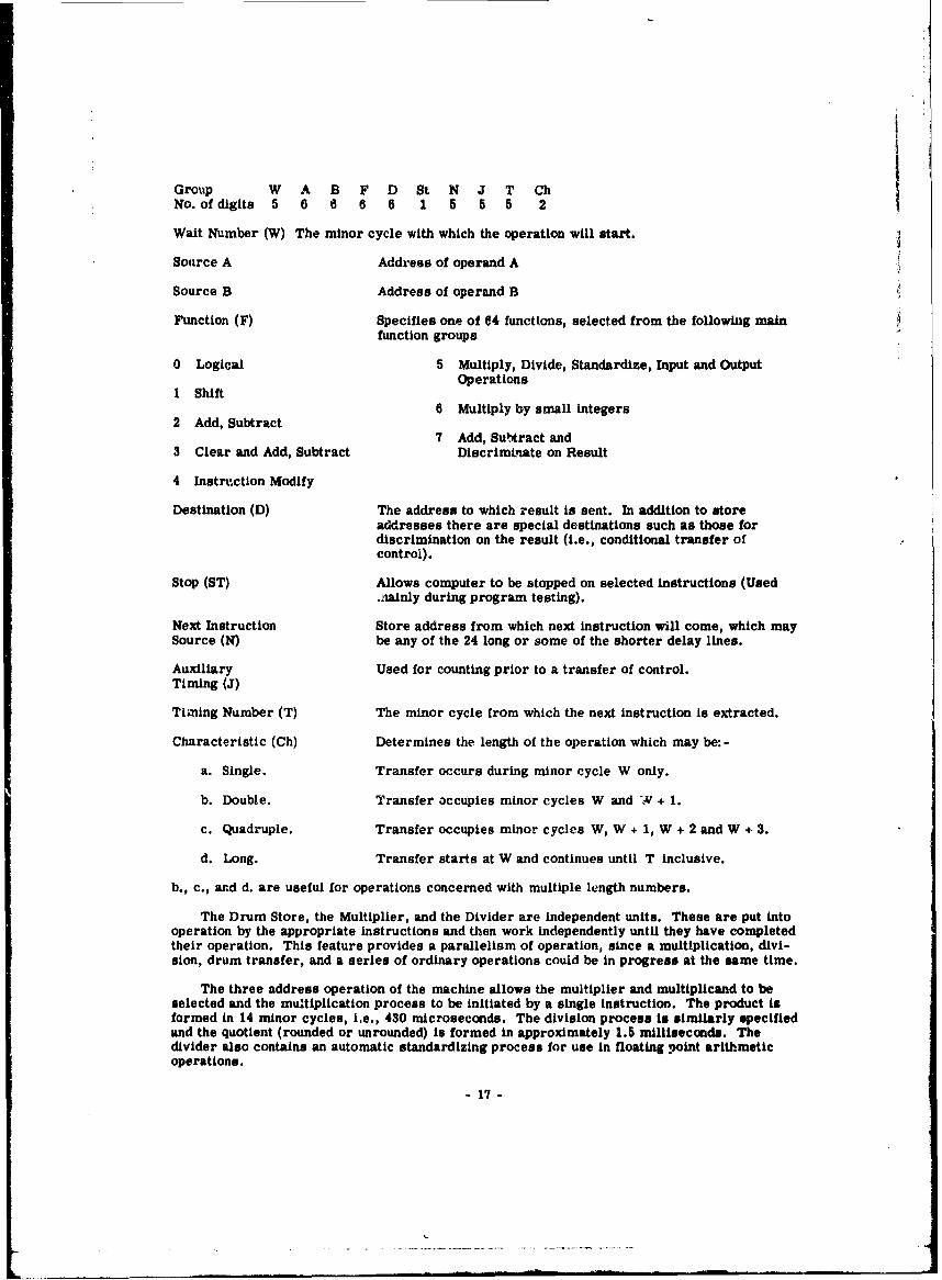
I
Group W A B F D St N J T ChNo. of digits 5 6 6 6 6 1 5 5 5 2
Wait Number (W) The minor cycle with which the operation will start.
Source A Address of operand A
Source B Address of operand B
Function (F) Specifies one of 64 functions, selected from the following mainfunction groups
0 Logical 5 Multiply, Divide, Standardize, Input and OutputOperations
1 Shift6 Multiply by small integers
2 Add, Subtract7 Add, Sul'ract and
3 Clear and Add, Subtract Discriminate on Result
4 Instruction Modify
Destination (D) The address to which result is sent. In addition to storeaddresses there are special destinations such as those fordiscrimination on the result (i.e., conditional transfer ofcontrol).
Stop (ST) Allows computer to be stopped on selected instructions (Used.aainly during program testing).
Next Instruction Store address from which next instruction will come, which maySource (N) be any of the 24 long or some of the shorter delay lines.
Auxiliary Used for counting prior to a transfer of control.
Timing (J)
Timing Number (T) The minor cycle from which the next instruction is extracted.
Characteristic (Ch) Determines the length of the operation which may be: -
a. Single. Transfer occurs during minor cycle W only.
b. Double. Transfer occupies minor cycles W and W + 1.
c. Quadruple. Transfer occupies minor cycles W, W + 1, W + 2 and W + 3.
d. Long. Transfer starts at W and continues until T inclusive.
b., c., ard d. are useful for operations concerned with multiple length numbers.
The Drum Store, the Multiplier, and the Divider are independent units. These are put intooperation by the appropriate instructions and then work independently until they have completedtheir operation. This feature provides a parallelism of operation, since a multiplication, divi-sion, drum transfer, and a series of ordinary operations could be in progress at the same time.
The three address operation of the machine allows the multiplier and multiplicand to beselected and the multiplication process to be initiated by a single instruction. The product isformed in 14 minor cycles, i.e., 430 microseconds. The division process is similarly specifiedand the quotient (rounded or unrounded) is formed in approximately 1.5 milliseconds. Thedivider also contains an automatic standardizing process for use in floating point arithmeticoperations.
- 17 -

The Magnetic Drum Store has a total capacity of 1024 long delay lines, i.e., about 1.5million digits, There are four drums each having 256 tracks, each track storing the contentsof one delay line. Each drum has 16 read heads and 16 write heads, the 256 tracks beingobtained by moving the heads as one unit into one of 16 discrete positions. Each drum is 6.75inches long by 5 inches diameter, allowing a linear digit packing of 100 per inch. The drum isdriven by a hysteresis motor running synchronously at 12,000 rpm, and is phase corrected soas to rotate exactly once in five major cycles of the machine.
Punched card and magnetic tape equipment will be provided for input and output. Theinstallation will initially consist of two machines. A broadside card reader, running at 450cards per minute, and a broadside card punch running at 100 cards per minute.
In order to read or punch 80 columns of a card the computer has an 80 digit inputdynamiciser and an 80 digit output staticiser.
The ACE has been designed and constructed to allow easy maintenance. Extensivemarginal checking facilities are provided and the chassis units are designed to give completeaccessibility to all components, valve connections etc.
The machine is housed in 10 cabinets, each having a cooled air circulation system. Eachcabinet is fitted with a rising door which permits immediate access to all the 24 chassis unitscontained therein. The number of valve envelopes is about 6000.
X 1 - N.V. ELECTROLOGICA - AMSTERDAM, HOLLAND
The electronic computer X 1 (see Digital Computer Newsletter, July 1957) is a product ofthe N.V. Electrologica, Amsterdam. It has been designed and developed in close collaborationwith the Mathematical Centre in Amsterdam, which has much experience in building electroniccomputers. It incorporates the most modern developments as, for example, transistors andmagnetic cores. Both of these have the merit of giving very long service.
The X I can be used for arithmetical and logical operations for business or for scientificpurposes; it works at the very high speed of 15,000 additions or subtractions, or 2,000 multi-plications or divisions per second.
By the application of transistors instead of thermionic valves power consumption hzi beenreduced to . few hundred watts and special ,-ooling apparatus is no longer needed in view of thesmall amount of heat produced. The dimensions of the basic machine are no greater than thoseof an ordinary writing-desk.
The storage, consisting of magnetic cores, comprises an "active" and "dead" part, bothwith the same access time, so that the elaborate procedure of optimum programming is nolonger needed. The active storage is used for variable data and current programmes. Thedead storage is especially suitable for the storingof fixed programmes such as often occur inbusiness administration; its component parts can readily be changed and as their cost is low,a large stock of fixed programmes ready for immediate use can bc maintained at moderate cost.In consequence, the size of the more expensive active storage can be kept smaller than wouldotherwise be possible.
The capacity of the standard equipment, 512 words active and 512 words dead storage, canbe expanded if necessary by adding supplementary units to a maximum of 32,768 words in all.
For the input of data, either punched cards or punched paper tape may be employed. Out-put is bj means'of punched cards, punched tape, or typewriter. The input capacity when tapeis used is 153 characters per iecond, the output being 25 characters per second, except that theoutput capacity of the typewriter is 10 characters per second. Punched paper tape for use withthe X 1 can, of course, be obtained as a by-product of suitable office machinery, e.g., type-writers, adding-and-listing, or bookkeeping machines.
18 -

For input in the form of punched cards either one or two reproducers may be coupled withthe X 1 with a capacity of 7,000 cards per hour for each reproducer. A fast reading unit withan input capacity of 42,000 cards per hour may also be used in addition to the reproducers if Iso desired. If all three are used the input capacity is 56,000 cards per hour against an outputcapacity of about 14,000 cards per hour. The fast readear mentioned could also act as a sortercontrolled by the X 1 computer. In linking an X 1 to a reader or reproducer, buffer storage isemployed and the computer can continue calculations during card reading and card punchingcycles.
Extensive facilities for operating and controlling the machine as well as for testingprogrammes are provided with the X 1. Notwithstanding the high degree of reliability of theX 1, both sections of the storage are provided with built-in parity controls. The reading andpunching apparatus is automatically checked, and control can also be applied to typewriteroutput.
The price of the X 1 briing6 the use of an electronic computer within the reach of medium-sized enterpri"ses. The capacity of the standard equipment can be increased by enlarging thestorage capacity, and by supplementary input and output devices. It is possible, for example,to begin with the use of a siall basic equipment and to expand it gradually as automationproceeds or as the volume of business grows. The machine is available either for outrightpurchase or on hire.
Instructions. Single address code.
Number System. Whatever the input and output medium used (punched cards, punched tapeor tyjpewriter) data are fed in or extracted in decimal form, the machine automatically trans-ferring to and from its Internal number system. The internal use of a binary system makesmaximum use of the storage capacity available. The machine works with a fixed decimal point.
Word length. 27 binary digits (bits); or 26 binary digits and one sign digit. This gives astorage capacity for numbers to about 67 million. Larger numbers up to about 4.5 x 10¹⁵ canbe stored by making use of two addresses. The programming of computations with such largenumbers is simple.
Registers. Inter alia two registers (A and S), each of 27 bits, and an address modificationregister (b) of 16 bits. All these registers are available for adding and subtracting. Formultiplication and division purposes the A and S registers are used as a double-length register.
Speed. Addition/subtraction, 64 microseconds; multiplication/division, 500 microseconds.
SIEMENS 2002 - SIEMENS & HALSKE AG - MUNICH, GERMANY
The Siemens 2002 is a medium-scale transistorized computer. It is a general purposedecimal machine with a word length of 12 decimals plus sign and an average speed of 2000operations per second. Special features of the 2002 include three index registers, the use ofthe instruction location counter for address modifications, the automatic address substitution,and fixed and floating point operations. The 2002 has a magnetic core memory of variable size(units of 1000, 2500, 5000, and 10,000 words, up to ten memory units can be connected with thecentral processing unit) and a magnetic drum memory with a capacity of 10,000 words. Inputand outi dAta are handled by punched paper tape, punched cards, and magnetic tape. Magneticcore bffit- s for the input and output units allow the execution of input and output operationssimultaneously with the operations in the central processing unit. A cathode ray tube unitpermits the analogue display of output data.
Word structure. The 2002 is a decimal machine, where a decimal digit is represented by afour-g-[it--fiiiary number (excess-three-code). A word can be interpreted by the machine infour different ways, namely:
- 19 -

1. As an instruction.
* M R 0 0 0 S A A A A A IS 1 2 3 4 5 6 7 8 9 10 11 12
Decimal 1 can be used together with the sign to mark an instruction. Decimal 2 servesseveral purposes. It indicates for instance, whether the result of an arithmetical or shiftoperation is to be rounded or not. The operation to be executed is identified by the threedecimals 3 to 5. Both decimal 6 (address substitution) and 12 (index tag) are used for addressmodifications. The address part of the instructions is given by decimals 7 to 11.
2. As a fixed-point number, with the decimal point being assumed on the left of the mostsignificant digit, the numbers being represented by sign and magnitude.
3. As a floating-point number, where the mantissa occupies ten (decimals 1 to 10) and thecharacteristic two places (decimals 11 to 12).
4. As an alpha-numerical expression with two decimal digits characterizing one alpha-numerical character.
Address modification. The usefulness of an instruction code depends greatly on the pos-sibility of performing automatically address modifications. The 2002 allows for modifying theaddress part of an instruction in two different ways, namely by "address substitution" and by"index register modification," this being dependent on the contents of position 6 (substitution)and position 12 (index register modification) of the instruction word. These two types ofmodification can be combined and are carried out as follows:
The control unit of the 2002 include three index registers, numbered 1, 2, and 3. Whenexecuting "indexable" instructions the number in position 12 of the instruction (in the instruc-tion register) determines the index register, the contents of which is to be added to the addresspart x (position 7 to 11) of the instruction. Number "4" in the index tag indicates that thecontents of the instruction location counter is to be added to the address part of the instruction.
After this modification of the address part by the contents of one of the index registers orby the contents of the instruction location counter, resulting in a modified address x1 , position6 of the instruction word is checked.
In the case the number in position 6 is "0," the instruction will be executed in the normalway with the modified address x1 . If the number in position 6 is "1," then the contents oflocation xl is read out of the memory, and positions 6 to 12 of the contents of location x1replace positions 6 to 12 of the instruction in the instruction register (address substitution).Then the cycle starts again with a modification of the new address part by the contents of oneof the index registeri or by the contents of the instruction location counter, dependent on thenumber in position 12 of the instruction word and so forth. The process ends, when after anindex register modification resulting in a modified address xn, position 6 of the instructionword contains "0." Following this the instruction (with address part xn) is executed in accord-ance with the instruction list.
If the instruction to be executed is "not indexable," the modifications by the contents ofone of the index registers are suppressed. In the case the number in position 6 is "0," theinstruction will be executed in the normal way. If position 6 of the instruction word contains"1," only positions 6 to 11 of the contents of location x replace positions 6 to 11 of the instruc-tion word in the instruction register. Then again position 6 of the instruction word is checkedand so on.
Instructions and apeed The 2002 contains 80 instructions:
1. 28 instructions for arithmetic opei ations for fixed-point and floating-point numbers,shift operations, and other specific operations. In order to increase the calculating speed,devices are provided which produce multiples of multiplicands and divisors. Special attention
-20 -

has been paid to the built-in unnormalized floating-point ar!thmetic, so that, roughly speaking,the precision of the results is about the same as the minima3 precision of the two operands.
2. 12 jump and other control instructions, one of whi:z:, the so called subroutine jumpUNT (unterprogramm) is executed as follows- supposed the instruction "UNr 3" is stored inmemory location a, then a + I is stored automatically by this instruction in memory location/3(precisely; in positions 7 to 11, all other positions being reset to 0), the next instruction to beperformed will be taken from memory location 3 + 1. The last instruction of a subroutine is afine example of address substitution. The (unconditional) jump instruction SPR (springe) forswitching the control to memory location a + 1 of the main program has the form "SPR 103where position % (address substitution) is equal to 1.
3. 9 instructions for index register operations, including Jump instructions dependent onthe contents of an index register.
4. 4 instructions for a transfer of data between drum and core memory in blocks ofvariable length.
5. 9 instructions for punched paper tape input and output.
6, 9 instructions for punched card input and output.
7. 7 additionai instructions for magnetic tape equipment.
8. 2 instructions for a cathode ray tube output unit.
The sign of an instruction is used for program testing. Normally the sign of an instructionis not considered by the control unit. After pressing a button on the control desk, instructionswith a positive sign are executed as usual, instructions with a negative sign initiate the follow-ing procedure:
1. The contents of the instruction location counter is stored in memory location 0.
2. The next instruction in sequence will be taken from memory location 1.
In memory location 1 for example there may be the start of a program printing the con-tents of the instruction location counter, of the accumulator a.s.f. (tracing). After the executionof this program the control can be switched back to the main program by a jump instruction"SPR 1 0," using address substitution.
All operation cycles of the 2002 are integral multiples of the "basic machine cycle," whichrequires 90 microseconds. One basic machine cycle is equal to the time interval necessaryfor adding the contents of a memory location to a number in the accumulator, including thereading out of the addend. Reading out of an instruction from the core memory, its inter-pretation by the control unit, and the address modification by index registers are performedin one basic machine cycle. Each address substitution requires another 90 microseconds.
The execution of an instruction is not normally controlled by the central control unit but byseparate circuits of the arithmetic, input and output unit a.s.f. That means that normally read-ing, interpreting, and address modifications of the next instruction are performed by the centralcontrol unit simultaneously to the carrying out of the preceding Instruction, provided the execu-tion of the preceding instruction requires more than one basic machine cycle. For this reasonthe numbers bnted under Operational Speed do not include the 90 microseconds for reading,interpreting, and address modification (by index registers) of the Instruction. The nextinstructions are even carried out during the execution of a preceding one, If this is possible,i.e., if the control circuits for carrying out the next instruction are not used by precedinginstructions. Under certain assumptions concerning the distribution of instructions of aprogram (25% additions, 25% multiplications, and 50% Instructions for organization a.s.o.) theaverage speed of the 2002 amounts to 2200 operations per second for fixed point and 1850 forfloating point calculations.
- 21 -
L

iipu'rat ionsI SIproeda (iii'lOttiIII re'atingI OAR III t il,' 01101,41d)
Adde ft sod point Ot) 11114, rop~potndlm
Multipl I I h
inMaedoby. The lastr Istrution.ni i The averae't acestime'w f ord to the'io adruo memoryki is%
retly reduer ed bowhen transfrring blpoks of iooreasinable length, v ~~The' drumgt fey a atrqinct tiitsi
23 milliseconds, Othe drum clock frequency St0O ke, The avivrag' access tMe' ito thlt, firat wiirdof a block !a about 19 milliseconds. With at word transfer tit 90 iirs'ecdth tranofetrtime of a block of n words Is (19 .ý n -0,09) millisocondsm. The average trunsfer thime At, 1t)00words from the drum memnory to the core' memory Its thereifore' 109 millise'conds.
In~pt-Output. Input and output data are' handled by 1%1a8ns of punchod patter tape', puint hiodcard, ia-i~ii peitic tape equipment, In the' case' of punche'd paper tapeo, data cvan beM roiad itobthe machine, one character per Instruction, with a speed up to 200 characte'rs per se'cond.Results are puniched onl patpor tape at a speed of 50 characters per arcond. A special buitlt-In~input ro~utine allows thf iaput of data without using a stored program,
The punched card control unit contains a core' buffer storage for e'ach punched card Inputreap. output. The buffer storage' has a capacity of 80 x 13 96n bits, thlt) valumnne' (rows) of the'buffer being the equivalent of the' columnis (row.) of the punched card, The' nei'l cutrit is readinto the input huffer start gre (the ecntonts of the output butffer storage is punehed into the', nextcard) by separate control circuits while calculating. A special column, numbered 0, ist pro-vided In the input buffer storage'. Any of the' 980 points of a vard can be' wired Into any p)ositiontof column 0.
Data Is read out of the' input buffer columnuwise,, beginning with columni 0, continuing withcolumn 1, 2, 3 ...... Up to 12 consecutile' colunmns can be re'ad by' one' Inttruction, the' giumi' cof 'iolumns as well as the buffer unit are' indicated by thle addresp part oif tilt) read insrtiuction,The execution time for reading 12 columns is 540 microsecenids. Data tit read into tht Accu-mulator. There are two groups of instructions for reading numerical and aatphanume'rivaicharacters, alphanumerical characters being represented by two decimtal digits. The' outputbuffer In filled columninise In a similar way. If a printer it) ito be' connectod with anl outputbuffer, the number of columns can be Increased,
The magnetic tape equipment is attachedt to tho 2002 in a nimilar way, The' tape' controlunit contains one or two buffers with a capacity of 1280 x 6 bits (ona' charavter per colunmn).
The net record on tape is read Into tho buffer storage' (ti~e contents of thle' buffer s'torage' iswritten on the tape) by read (write) instiuctions by separate c,)ntrol circuits wvhile calculating.If two buffers are installed, two records can be transferred simultaneously to or front twol tape'units. Up to 10 tap~e units can be connected with the tape' control unit.
The Instructions for readi~ig datqL out of the tape buffer Into the accumulator and for fillingthe tape buffer ft am the accumulator a'e the same as for the punched card buffers. Thleexecution time for readling 12 columns Is 270 micro~.econds. Because of the' length of tile tapebuffer, four block traicafer Instructions are provided, which transfer thle next n columns of tapebuffer k into the car.ý memory, beginaiing with memory location x resp. In like mianner the' datA

stored in the core memory beginning with memory location x, transfers into the next n columnsof tape buffer k. Two instructions serve the transfer of alphanumerical and two instructionsthe transfer of numerical data.
Special instructions permit the sensing of the conditions of each input and output unit.Thus, for example, each input and output buffer is equipped with a flip-flop, which can besensed and is "1" during the reading In of the next record (punched card) or during writingthe contents of the buffer on tape or punched card. This makes it possible to continue theprogram up to the very moment the required input or output buffer gets free. The simultaneouscarrying out of several input and output onerations is possibIP because of independent controlcircuits for each input and output buffer.
Certain applications necessitate a digital-analogue conversion of results. A cathode raytube unit permits the analogue display of output data, 3 decimal digits representing the xcoordinate and 3 decimal digits the y coordinate. Generation of axes and diagonals is possibleby one instruction. The cathode ray tube unit can be furnished with a camera unit, the trans-portation of the film is effected by the central processing unit.
SOCIETE D'ELECTRONIQUE ET D'AUTOMATISME - COURBEVOIE, FRANCE
The SOCIETE D'ELECTRONIQUE ET D'AUTOMATISME has just completed the installationof 2 large electronic sets for data processing (statistics and management). The first is at theINSTITUT NATIONAL de la STATISTIQUE et des ETUDES ECONOMIQUES in the establishmentof general type statistics and various theoretical work. The second is fcr accountant work,statistics, and operational research at the COMPTOIR FRANCATS des PRODUITS SIDERUR-GIQUES. Their order was placed in October 1956, and the machine was delivered October 24,1958, and was put at the client's disposal on November 20.
These two installations consist mainly of a general purpose digital computer CAB 3030with a recorded internal program and three or four magnetic tape equipments.
CAB 3030. The 3030 works with a fixed point, or floating point by program. The machir .word is 32 binary digits, including one for sign, and one for parity. Negative numbers arerepresented by their 2's complement in order to obtain immediate notification of overflow.Instructions are single address-except for those involving accumulators, which areaddressable by a second address.
The machine is serial, with 4 accumulators, and a parallel binary multiplier. The executionof one order, and the finding of the next, are carried out si, iultaneously.
Storage coi.sists of magnetic drum with 128 tracks of 128 words each (16,384 words), aquick access ferrite core store with a capacity of 1,024 words. Transfers between the dr'imand the core store are performed automatically. A parity digit is used for control in thetransfer of numbers and instructions between ýhe different elements.
Inputs are: Ferranti photo-electric punch tape reader (200 or 400 characters per second);Fiexowriter electric typewriter; and magnetic tape equipment (30 groups of 32 words or 160characters per second).
Outnuts are: Flexowriter electric typewriter; S.E.A. high speed punch at 45 charactersper second; S.E.A. electronic printer "Numerograph" on microfilm (2,000 characters persecond); andi anagnetic tape equipment.
The 30310 has 3600 valves and 35,000 diodes, Power required is 30 kilowatts.
Numerograph. The first Numerograph has recently been set up at the Societe MONSAVONL'OREAL. it is a fast electronic printer which enables the immediate printing on standardmirro(ilm -c* the output from an electronic computer at a rate which can reach 2,000 charac-ters per second.
9 3-

A 6-bit code at the input controls two types of ordiers, Writing and Auxiliary.
Auxiliary orders: Capitals - Lower case - Advance - Return - Tabulation - Slacing -Colour change. The "Capital" and "Lower Case" orders enable the selection to be made fromthe group corresponding to a given cathode ray tube where the characters originate. Thecharacter writing orders, as well as "Advance," "Tabulation," and "Spacing" determine theposition on the line. A special electronic counter performs the same part as the carriage ona typewriter. The position of each character is set on a special cathode ray tube based on theinformation received from the counter, and a camera placed in front of this tube registers theresults. The "Spacing" order moves the film forward. The "Change colour" order changesstandard type to italics, through a simple electronic anamorphosis.
Writing orders: The coded information positions the "Character" cathode ray tube spot,and in this way selects the corresponding character drawn on a ,'ansparcnt sighting screen.At the same time the "photographed" tube spot is pl-ree- on thc l.nc -:;hich Is written at theplace indicated by an Internal counting and tabulation system in the "Numerograph." The 2spots synchronously sweep the rectangle surrounding the character to be reproduced. A photo-electric cell, placed in front of the "character" cathode ray tube, transmits to the "photo-graphed" cathode ray tube, In front of which a camera photographs the characters as they areinscribed.
At present, groups of 42 "Capital" and "Lower Case" characters are available. This canbe increased to 50 for each group. The number of groups could subsequently be increased to10 (each approximately 40 characters).
At the present both straight and Italic characters are available. The introduction ofauxiliary orders "Index" and "Exponent" could subsequently be envisaged, with changes in sizeinvolving whole groups of characters which would give, with the previous combinations, 3 sizesof characters.
Printing rate is 840 microseconds per character. Line spacing requires 10 milliseconds.These times could be subsequently reduced to 560 microseconds and 5 milliseconds (with aforward film speed limit of approximately 150 lines per second).
Most errors are automatically detected with the exception of character alignment faults(framing of characters on the line) which can be corrected by a simple and rapid adjustment.
TAPE MERGING EQUIPMENT - ULTRA ELECTRIC LIMITED -LONDON, ENGLAND
Ultra Electric's first entry into the Data Processing field is the fully-transistorized TapeMerging Equipment, which was shown at the London Computer Exhibition.
This equipment is primarily intended to combine the information recorded on two punchedpaper tapes, automatically producing a new tape which contains the result of the mergingoperation.
In a computer installation fitted with paper tape equipmeat, the Tape Merging Equ ipmenmakes it possible to exploit some of the powerful data-processing techniques which have beenevolved for magnetic tapes, so that the time of using a computer can be much reduced and Itbecomes practical to do small and medium data-processing tasks.
Further, use of this equipment in conjunction with small computers opens up new uses forthem in data-processing, and it has applications in the building-up of programmes.
A typical application is in up-dating an inventorv file. The two Input tapes are thebrought-forward file and a tape containing amended Items, the latter having been prepared onthe computer. The amended items tape also contains programme instructions, which cause theequipment to copy items from -PIher of the two input tapes or to ignore an unwanted item on the1rought-forward file tape. In 'his way an up-dad " c-at-rrorv:ard file is p'reared as an off-llne.i-p.ratin.

The equipment can also tunction as a high-speed tape copier or w&., rAorwparator, or cancarry out these two functions simultuineouely.
ELECTRONIC COMPUTER SZ [ON - THE WEIZMANN INSTITUTEOF SCINNCE.. REHOVOTH, ISRAEL
WEIZAC'. The memory capacity of WEIZAC (see Digital Computer Newslotter, Januaryt14t5el-au %" on boosted by the installation of tuu magnetic tape handlers, using Potter 905 tapetransports. The desagn ol Lav tape circuits is conservative, character repetition rate being5000 per second. Theme tape units were used heavily during 1958, doing mostly high-ordermatrix work. Present plans call for the installation of two additional tape units during 1959,doubling the character rate,
An off-line device has been built for the print-out og data from magnetic tape onto papertape, via a magnetic drum. This unit is now undergoing final tests.
Total Scheduled
Code Production Computation Idle Engineering UnscheduledMonth sChecking Time Time and Breakdowns
MonthDevelopment
Hr.. Mina. Hr.. Mins. Hr-. Mina. H.--. Mine. Hr. Mina. Hre. Mina.
Oct.57 78 48 252 02 330 50 5 23 84 40 20 05
Nov 87 43 309 09 376 52 5 48 70 46 8 03
Dec 108 37 332 27 439 04 5 46 58 49 14 14
Jan. 58 52 48 408 47 461 33 5 45 79 14 30 52
Feb 53 22 378 33 431 55 - 58 76 26 44 28
March 54 57 491 04 548 01 2 42 77 55 44 42
April 51 19 568 48 618 05 1 51 53 32 31 47
May 88 49 574 21 641 10 1 49 65 16 20 25
June 57 18 532 12 589 30 - 05 52 50 52 24
July 42 25 554 31 598 156 3 28 55 27 48 42
Aug 41 45 561 38 603 21 - 23 60 01 57 30
Sep 86 57 416 23 483 20 2 25 40 07 32 58
Oct 45 51 617 30 863 21 2 28 40 45 24 18
Nov 80 47 547 41 608 28 4 56 62 20 42 58
Dec 88 47 527 13 616 - 1 5" 66127 48 48
936 1. 7070 15 8008 26 45 137 924 35 520 1
Recent problems. They have solved for the first eigenvalue of a determinant of order1078. The problem arose in connection with the determination of the energy level of the groundstate of Helium. They have also been engaged in thie development of methods of carrying out
-25 -

algebraic operations on WEIZAC, The need for this approach arose kn an investigation on thepropagation of a seismic pulse in a layered elastic half-space.
A recent trend in their work has been to operate with invisible equations: the equationsbe•ome so long that it Is impossible to write them down, so that WEIZAC increasingly operateswith equations which it generates itself.
COMPONENTS
HIGH SPEED PRINTER - A. B. DICK CO. - CHICAOO, ILLINOIS
Time, Inc. has awarded a contract to A. B. Dick Company of Chicago, IPlinois for 2address-label printing systems, each capable of printing in excess of 130,000 1" x 2-3/4"labels per hour per system from digitally coded magnetic tape. Each system will include anA. B. Dick Model 910-1 label printer and a Model 940A tape reader and buffer unit.
The printer unit employs A. B. Dick Company's recently announced VIDEOGRAPH high-speed printing process (see Digital Computer Newsletter, July 1958). Principle element of theprocess is a special CRT having a dense matrix of fine wires permanently bonded through theface-plate instead of the conventional phosphor screen. Deflecting and modulating the electronbeam across the inner side of the matrix while simultaneously transporting dielectricallycoated paper past the face of the tube deposits latent charges on the paper, which are thendeveloped by "dusting" with a powder. The visible images are then fixed on the surface.
In employing this process with digital input systems, a specially developed charactergenerator is utilized which converts pulses into the alphanumeric video waveforms requiredto drive the electrostatic printing tube at writing rates that may be in excess of 20,000 char-acters per second.
In the Time, Inc. equipment, the tape reader and buffer unit (TRBU) will fully edit theinformation provided on the magnetic tape input and provide a continuous flow of data to theprinter. The unit will employ a 2184 character core buffer to receive the edited information,from which the city and postal zone codes are read into a 144 character magnetic storage unitfor recirculation into the output for the successive series of labels directed to the same cityand zone.
Delivery of the two printing systems to the magazine's Subscription Service Division inChicago is scheduled for June 1960. Major subcontractors include Stanford Research Institute,Cook Electric Company, and Telemeter Magnetics, Inc.
HIGH SPEED DIGITAL PLOTTER - LOCKHEED MISSILES AND SPACE DIV. -SUNNYVALE, CALIFORNIA
The High Speed Digital Plotter developed by the Computer Research Department of theLockheed Missiles and Space Division accepts magnetic tape from IBM or Remington RandUnivac Computers and records the output on electrolytic facsimile paper. The maximumplotting rate is in excess of 4,000 data points per second, in addition to coordinate lines whichare automatically generated.
Data points are recorded on facsimile paper by the passage of current from selected styli,which are arranged in a line perpendicular to the direction of paper travel. Spacing betweenstyli is 0.01 inch. The paper feed rate and electronic timing allow marking of adjacent points0.01 inch apart perpendicular to the stylus array. Thus, accuracy is 0.01 inch for both X andY coordinates. Many curves, including a complete coordinate system, can be written simul-taneously with this plotter.
The use of the high speed plotter has already proven of great value in speeding data reduc-tion. It is now possible to produce completely annotated digital plots within a few hours following
- 26 -

I
a test flight. With the great speed and flexibility of the plotter, it should prove to be anincreasingly valuable tool for reducing data.
SYSTEMS COMPONENTS - PACKARD BELL COMPUTER CORP. -
LOS ANGELES, CALIFORNIA
The Impact Prediction Systems for Vandenberg Air Force Base has been delivered. Thissystem is based on the conversion of shaft position information into digital form, computingcertain functions, and converting the output to voltages for display on analog plotters. A paperdescribing this system is available for anyone who wishes to write for it.
Certain systems are being made in which a Bendix G-15 general purpose computer is beingtied to an analog computer. In one typical system, there are the channels of analog-to-digitalinformation being multiplexed into the G-15, and three channels of digital-to-analon informationbeing transferred back to the analog computer. The cost of the coupling unit is approximately$25,000. This same technique may be used on other computers, and on more elaborate systems.
SERIES RB STORAGE UNITS - TELEMETER MAGNETICS, INC. -LOS ANGELES, CALIFORNIA
The Series RB random access data storage units have been announced by TelemeterMagnetics, Inc. These memory-buffer units offer addressable random access, sequentialaccess, or a combination of both as desired, and have a combination of features not previouslyrealized.
High Speed 200 kc operating rate.
Long Term Reliability Solid state active elements; conservative derating of compo-nents; advanced design and manufactqring techniques.
Wide Range of Capacities From 256 to 1024 words of from 4 to 20 bits per word.
Random or Sequential Access Addressable storage registers for regenerative read/write orbuffer operation in a sequential non-regenerative mode.
Binary or Decimal Either binary or binary coded decimal addressing.
Variable Input/Output Will accept pulses or levels of either polarity and input maybe changed during operation. Output Is equally versatile.Accepts and emits single-ended or double-ended information.
Speed Load or unload a word (all bits in parallel) in 5 microseconds.Random access with regenerative storage - complete cycle in10 microseconds.
Operating Mode Sequential loading and unloading. Random access addressingfor loading and unloading or regenerative read/write. Opera-tions can be intermixed in any manner desired without loss ofspeed.
Control Levels and Signals Input and output levels may be single ended or double endedand a ONE may be represented by -5 or +5 volts as desired.Input pulses must rise to between 2 and 10 volts from aquiescent level of -5 volts. Rise time between 0.2 and 1.0microsecond. Output pulses rise to 5 volts from a quiescentlevel of -5 volts. At the top of the pulse 25 milliamperes areavailable. Reference levels of *5 volts are available at theoutput of the unit.
27-

Clearing Electronic clearing is provided and address register may becleared to the all ONE or all ZERO state.
Power Required Nominal 115 volts, 60 cps, less than 250 watts. Satisfactoryoperation is obtained from supply voltages between 100 and130 volts.
Dimensions Size depends on capacity. Largest Series RB unit approxi-mately 30 inches high by 14 inches deep. All units are sup-plied for relay rack mounting.
Environment Reliable operation between 00 and 55*C. Unaffected byhumidity.
Low Cost Series RB random access storage units are priced below mostmemory units designed to do only a portion of the job thesememories will handle.
MISCELLANEOUS
CONTRIBUTIONS FOR DIGITAL COMPUTER NEWSLETTER
The Office of Naval Research welcomes contributions to the NEWSLETTER. Your con-tributions will assist in improving the contents of this newsletter, and in making it an evenbetter medium of exchange of information, between government laboratories, academicinstitutions, and industry. It is hoped that the readers will participate to an even greater extentthan in the past in transmitting technical material and surgestions to this Office for futureissues. Because of limited time and personnel, it is often impossible for the editor to acknowl-edge individually all material which has been sent to this Office for publication.
The NEWSLETTER is published four times a year on the first of January, April, July, andOctober, and material should be in the hands of the editor at least one month before the publi-cation date in order to be included in that issue.
The NEWSLETTER is circulated to all interested military and government agencies, andthe contractors of the Federal Government. In addition, it is being reprinted in the Communica-tions of the Association for Computing Machinery.
Correspondence and contributions should be addressed to:
GORDON D. GOLDSTEIN, EditorDigital Computer NewsletterInformation Systems BranchOffice of Naval ResearchWashington 25, D. C.
- 28 -

Government regulations require the maintenance of up-to-date
distribution lists for all periodicals. The form below is
for your convenience to indicate necessary changes or cor-
rections. Do not return this sheet if your presenx listing
in correct. Please send toCode 437, Office of NavaJ Research,
Washington 25, D. C.
- TO: DIGITAL COMPUTER NEWSLETTER, Code 437, Office of NavallI Research, Washington 25, D. C. II ]j REVISE AS INDICATED BELOW II II [] DELETE FROM DISTRIBUTION LIST
I (Please print or type) IFrom: PRESRNT ADDRESS (The complete To: CORRECT ADDRESS
present address, as it appears on theI envelopes MUST be listed here)
I I
I II
S INAU DATE I