Embed Size (px)
Citation preview
Digital Cable Records Management System
(A solution for Cable Records management using Geo Enabled Surfing on Customer Access Network (gSCAN))
An initiative of BSNL, Kerala Circle

Digital Cable Records Management System
Why DCRMS?
1. To Reduce Access Network Fault Rectification Time.2. To enable Focussed/Location based Marketing.3. Make Spare Pair Availability information on Finger Tip.4. To Check the feasibility of new connections at Junction Points.5. To Know the Customer Location and Link from MDF to Customer Premises.6. Preparation of Cable Diagram with Google Map
How it is different from Conventional CRMS Systems?
1. Integrated with CDR data to fetch maximum information on Cable Terminations.2. Geo Enabled Interfaces will enable the Geographical Area View during data entry.3. Multi-Tier architecture for Data Entry in a Phased Manner.
Digital Cable Records Management System
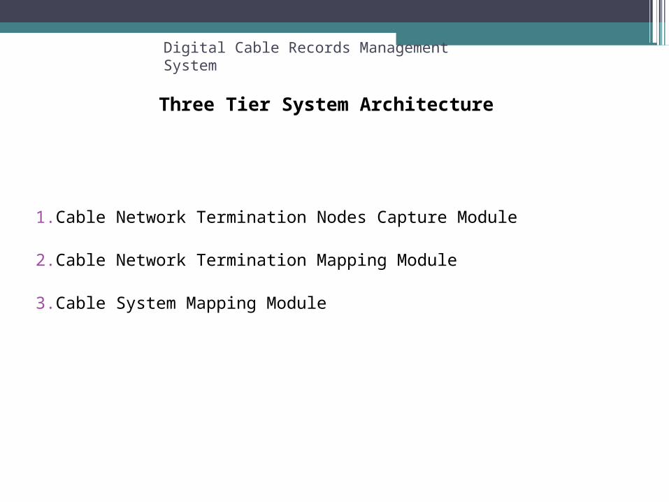
Three Tier System Architecture
1. Cable Network Termination Nodes Capture Module
2. Cable Network Termination Mapping Module
3. Cable System Mapping Module

Digital Cable Records Management System
Multi Tier Data Capture DCRMS
1. Customer Transfer from CDR
2. Master Data Capture from CDR
3. Master Data Entry/Edit by
Exchange
4. Cable Terminations
Mapping
5. Cable Network Entry
6. Cable System Mapping

Digital Cable Records Management System
Data Sources
1. CDR Data
2. MDF Diagram
3. Primary Cable Diagram
4. Distribution Cable Diagram
5. Other sources

Digital Cable Records Management System
Data Capture
1. Customer Transfer from CDR 2. Master Data
Capture from CDR
3. Master Data Entry/Edit by Exge
4. Cable Terminations
Mapping
5. Cable Network Entry
6. Cable System Mapping
CDR/IT
1 Customer Master
2 Termination Details
3 Main Locality
4 Sub Locality
IT
1 Pillar
2 DP
Exchange
1 Cable Routes
2 Locations
3 Pillar Locations
5 DP Locations
4 DP Termination Size
Exchange
1 MDF-Pillar Mapping
2 Pillar-DP Mapping
Exchange
1 Cable Along Routes
Exchange
1 Mapping of Cables at MDF, Pillars and Joints

Digital Cable Records Management System
Main Locality
Sub Locality
Cable Routes
CDR
Locations
DCRMS
Roads in which Cables are Laid
Locations of Pillars, DPs, Joints and Diversions
Concept of Main Locality, Sub Locality, Routes and Locations

Telephone Exchange
1 Exchange Location
2 Exchange Area
3 Cable Exit Face Line
4 Zoom Factor (Default 16)
Step 1 : Exchange Entry in CRMS
Digital Cable Records Management System

Digital Cable Records Management System
Cable Routes
It is the route along which the cable is laid in the Main Locality. This
is Mandatory. Two Interfaces are available
1. Text Mode Interface
DCRMS=>Master Data=> Cable Route Details Entry
2. Graphical Mode Interface in gSCAN

Telephone Exchange
1 Route Name
2 Route Type
3 Route Start LatLon
Step 2 : Routes Entry in CRMS/gSCAN
Digital Cable Records Management System
Vayalar Statue-PMG Bose Statue Road
Nandancode Road
Moscat Hotel Road

Digital Cable Records Management System
Locations
It is a point where Pillars, DPs , Joints etc are situated in a sublocality.This is mandatory.
Two Interfaces are available
1. Text Mode Interface
DCRMS=>Master Data=> Location Details Entry
2. Graphical Mode Interface in gSCAN

Telephone Exchange
1 Route
2 Sub Locality
3 Location Name
4 Location Marked Side
5 Location LatLon
Step 3 : Locations Entry in CRMS/gSCAN
Digital Cable Records Management System
PillarDPs
Joints
Diversions
Devarajan Statue
Kanakanagar
LMS Jn
PWD Office
Corporation Office
Hera Flat

Digital Cable Records Management System
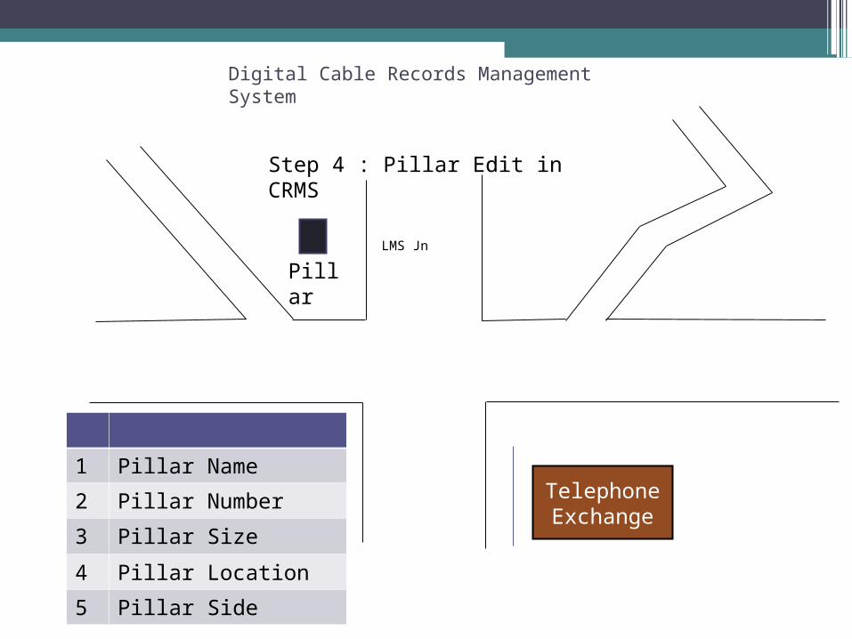
Pillar Edit
Pillar Data with Pillar No and Name will be Made available from CDR.
Pillar Name and Pillar Size can be edited.
Location and Side should be added
Text Mode Interface
DCRMS=>Master Data=> Pillar Details Entry
Telephone Exchange
1 Pillar Name
2 Pillar Number
3 Pillar Size
4 Pillar Location
5 Pillar Side
Step 4 : Pillar Edit in CRMS
Digital Cable Records Management System
PillarLMS Jn

Digital Cable Records Management System
DP Edit
DP Data with DP No and DP Name will be Made available from CDR.
DP Name , DP Size and No of DP Terminations can be edited.
Location and Side should be added
Text Mode Interface
DCRMS=>Master Data=> DP Details Entry

Telephone Exchange
1 DP Name
2 DP Number
3 DP Size
4 DP Terminations Size
5 DP Location
Step 5 : DP Edit in CRMS
Digital Cable Records Management System
DPs
PWD Office
Corporation Office

Digital Cable Records Management System
MDF-Pillar Mapping
MDF Tags and Pillar-In Tags can be Mapped using this Interface.
Text Mode Interface
DCRMS=>MDF-Pillar Mapping
MDF No
Pillar
CTBox
Tag From
Tag To
Vertical
CT Box
Tag From
Tag To

Digital Cable Records Management System
Pillar-DP MappingPillar Out Tags and DP Tags can be Mapped using this Interface. Jumpering on PillarIn - PillarOut will happen automatically.
Text Mode Interface
DCRMS=>Pillar-DP Mapping
CTBox
Tag From
Tag To
Pillar
DP
Tag From
Tag To

Digital Cable Records Management System
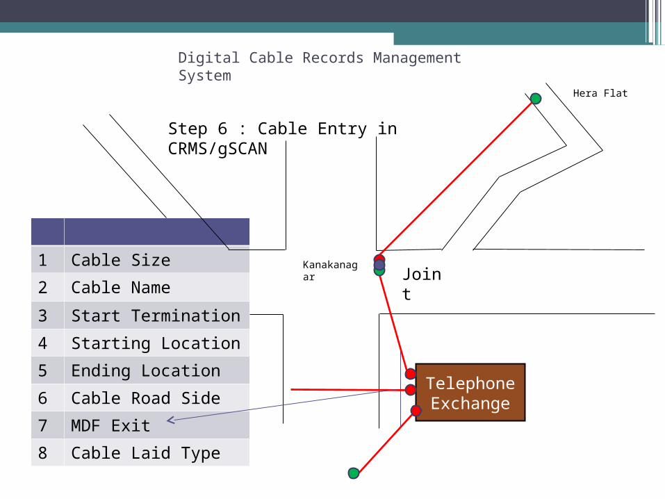
Cable Network Entry
Cable Laid along routes can be added through this module.
100% Data to be collected and recorded in the system.
Two Interfaces are available
1. Text Mode Interface
DCRMS=>Cable Network Entry
2. Graphical Mode Interface in gSCAN
Telephone Exchange
1 Cable Size
2 Cable Name
3 Start Termination
4 Starting Location
5 Ending Location
6 Cable Road Side
7 MDF Exit
8 Cable Laid Type
Step 6 : Cable Entry in CRMS/gSCAN
Digital Cable Records Management System
JointKanakanagar
Hera Flat

Telephone Exchange
Step 7 : Cable Diversions in CRMS/gSCAN
Digital Cable Records Management System
JointKanakanagar
Hera Flat
SFS Flat Jn
Convent School Jn
Petrol Pump Jn
Exchane Jn
Digital Cable Records Management System
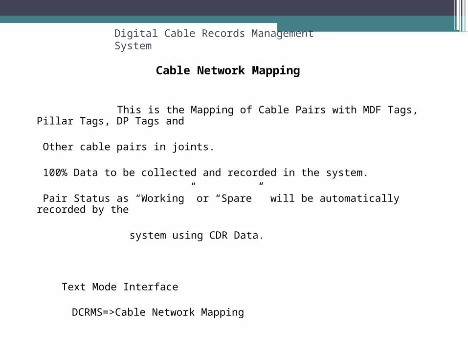
Cable Network Mapping
This is the Mapping of Cable Pairs with MDF Tags, Pillar Tags, DP Tags and
Other cable pairs in joints.
100% Data to be collected and recorded in the system.
Pair Status as “Working” or “Spare” will be automatically recorded by the
system using CDR Data.
Text Mode Interface
DCRMS=>Cable Network Mapping

Telephone Exchange
Step 8 : Cable System Mapping in MDF using CRMS
Digital Cable Records Management System
JointKanakanagar
Hera Flat
SFS Flat Jn
Convent School Jn
Petrol Pump Jn
Exchane Jn
Cable Name
Pair From Pair To MDF Vertical CTBox
1200/0.5 1101 1200 1 18 2
CTB Pair From
CTB Pair To
Tail End C
1 100 Joint
In MDF

Telephone Exchange
Step 9 : Cable System Mapping in Joint using CRMS
Digital Cable Records Management System
JointKanakanagar
Hera Flat
SFS Flat Jn
Convent School Jn
Petrol Pump Jn
Exchane Jn
Cable Name
Head End Pair From
Head End Pair To
Head End Cable
Head EndPair From
Head end Pair To
1000/0.5 901 1000 1200/0.5 1101 1200
Terminated In
Joint

Digital Cable Records Management System
Feasibility Check
Using this interface, feasibility can be checked if any of the following is known.
1. DP Number/DP Name 2. Location
3. Sub Locality 4. Nearest Telephone Number of Applicant
System will give the feasibility report from MDF to DP. If required, the pair can be marked as a reserved pair.
Text Mode Interface
DCRMS=>Feasibility Check

Digital Cable Records Management System
Add-Ons
Phone Number Edit
If required, any terminations regarding a Phone Number can be edited through this link.
Text Mode Interface
DCRMS=>Phone Number Edit
Status Change
The status of Spare Tags can be changed through this interface.
DCRMS=>Status Change.

Digital Cable Records Management System
Action Plan
1. The rollout date needs to be decided and to be inputted by the concerned SSA for each set of exchange.
2. The action plan and rollout progress will be coordinated centrally by Circle office (OP Section/ L2 DCRMS – L2 Team)
3. For any queries / support, field unit may contact only through [email protected] (IT Cell-L3 Team)
4. Field units may ensure correctness of data extracted from CDR (Pillar / DP / Locality / TAGs / Verticals) before operating DCRMS.
5. Field units may ensure the synchronization of termination data in both CDR and DCRMS simultaneously, whenever it occurs.
Digital Cable Records Management System
Thank You