Embed Size (px)
Citation preview

Digital Bidirectional Talk System
Installation Guide
V1.2.0

Chapter 1 System Structure
VTO and VTH are connected as a tree. VTO has a 12V DC adaptor supplying it with
power while switch has a 24V DC adaptor supplying it with power.VTO and VTH are
connected via switch. The switch supplies VTH with power via network cable. Electric lock,
magnetic feedback, door sensor and unlock button all can be connected to VTO, but the
VTO does not supply them with power. An example for system framework. See Figure 1-
1.
Figure 1- 1

Chapter 2 Notifications
1. Please avoid the following interferences:
As an example.
Direct sunlight Rain Strong electricity Fire
2. Power adaptor voltage:
Input voltage 100V-240V~50-60Hz AC; output voltage: 12V DC
Input voltage 100V-240V~50-60Hz AC; output voltage: 24V DC
3. Cable
According to distance LN between VTO and VTH, select cable.
Cable 0< LN ≤50m 50< LN ≤100m
UTP Cat5e/Cat6:10 ohm/100m Ok Ok
UTP Cat5e/Cat6:18.8 ohm/100m Ok Not ok
We do not recommend LN over 100m.
4. Power line
According to distance LC between adaptor and VTO, select power line.
Power line 0< LC ≤30m 30< LC ≤100m
20AWG Ok Not ok
18AWG Ok Ok
17AWG Ok Ok
Note: Before plug in, please make sure + and – end are correctly matched to
power end.
5. Device and embedded box
Device Embedded box
IH-6310
IH-6311 86 box /120 box
IH-D7710Z
IH-D7711Z 86 box

Chapter 3 FAQ
Q:I cannot boot up device.
A:
1. Check if the device is plugged into power. Digital VTO requires power voltage of
10V~15V.
2. If VTH is supplied with power by 2-pin port, check VTH’s power supply. It requires
voltage of 10V~15V.
3. Check if network cable is loosened. Switch supplies VTH with power of 22V~26V.
Q:VTO cannot call VTH.
A:
1. Check if VTH has registered on VTO.
Q:Low volume.
A:
1. Adjust VTO volume and call volume with VTH.
Q: VTH has no video or video quality is poor.
A:
1. In VTO web interface, switch video format to WVGA.
2. Do not place VTO under poor light or direct sunlight.
Q: I cannot unlock.
A:
1. You need to check if Model VTO supports swiping card to unlock.
2. Check if VTO access control module connection is loosened.
3. Electric lock is not correctly connected, or has no voltage output or output is too low.
Q: Door sensor alarm.
A:
1. Check if door is stuck.
Q: I cannot issue card. (For device with card swiping function only)
A:
1. VTO must support card issuing and card swiping.
2. Use IC card only.
.

Chapter 4 Installation Test
Note: The adaptor is not connected to city power grid in step 1-2.
4.1 Install VTO
4.1.1 Connect wire in embedded box to VTO
Step 1 Definition of ports:
The switch is connected to VTO’s network port.
Figure 4- 1
01. Network port: to external switch (IN port)
02. 3-pin 1: to lock control end 1
03. 3-pin 2: to lock control end 2
04. Power port: to input 12V DC power
05. Test port: to test device port
See Figure 4- 1.
General types of lock in market are unlocking with power and unlocking without power.
Here make electric lock and Magnetic lock as example.
Step 2 Install electric lock and unlock button
Figure 4- 2

1. When connect VTO to electric lock, make electric lock + toward VTO NO-end
(02.3-pin 1) and electric – toward VTO COM-end (02.3-pin 3).
2. When connect VTO to unlock button, make unlock button’s one end toward VTO (03.
3-pin 2) ALM 2-end and unlock button’s other end toward VTO (03.3-pin 3) GND-end.
See Figure 4- 2.
Step 3 Install door sensor
Figure 4- 3
1. When connect VTO to door sensor, make door sensor + toward VTO (02.3-pin 2)
NC-end and door sensor – toward VTO (02. 3-pin 3) COM-end.
2. When VTO is connected to door sensor for its magnetic feedback, make magnetic
feedback’s one end toward VTO (03. 3-pin 1) ALM1-end to unlock and make magnetic
feedback’s other end toward VTO (03. 3-pin 3) GND-end.
See Figure 4- 3.
Step 1 Definition of ports:
VTH can be connected to any port on VTO.
Figure 4- 4
01. Power port: to input DC 12V.
02. Lock port: to access control module
03. Network port: to switch (switch IN port)

See Figure 4- 4.
Step 1. Port definition is shown in Figure 4- 5.
Switch is at VTO network port.
Figure 4- 5
01. 10-pin port: connect to door lock, sensor feedback and unlock button. And provide
reserved port for other devices.
02. Power port: to input 12V DC power.
03. Network port 1: insert cable (RJ45 crystal head).
Step 2. Install electric lock and unlock button. See Figure 4- 6.
Figure 4- 6
When Villa VTO connects to electric lock, electric lock’s positive end connects to NO-end
(10-pin port 2)of villa VTO and electric lock’s negative-end connects to COM-end (10-pin
port 1)of villa VTO.
Villa VTO connects to unlock button, and unlock button’s one end connects to ALM1-end
(10-pin port 5) of villa VTO, unlock button’s other end connects to GND-end (10-pin port 4)
of villa VTO.
Step 3. Install door sensor lock. See Figure 4- 7.

Figure 4- 7
When villa VTO connects to door sensor lock, positive end of door sensor lock connects to
NC-end(10-pin port 3) of villa VTO and negative end of door sensor lock connects to
COM-end (10-pin port 1) of villa VTO.
When villa VTO connects to door feedback inside door lock, one end of door feedback
connects to ALM2-end (10-pin port 6) of villa VTO, and the other end of door feedback
connects to GND-end (10-pin port 4) )of villa VTO.
4.1.2 Fix VTO onto embedded box.
Figure 4- 8
1. Remove screw a under VTO, and remove decoration cover ①;
2. Use screw b to fix VTO onto 86 box ③ inside wall ④;
3. Use screw c to fix VTO onto wall if needed;
4. Install decoration cover ① onto VTO ②, and use screw a to fix.

See Figure 4- 8.Error! Reference source not found..
Figure 4- 9
1. Use screw b to fix bracket onto 86 box embedded/120 box embedded inside ③.
2. Use screw c to fix bracket on ③.
3. Install VTO ① on VTH bracket ②, and fix with screw a.
See Figure 4- 9.Error! Reference source not found.
4.2 Install VTH

4.2.1 Connect wire in VTH embedded box to VTH port. Connect network port to
cable which connects to the switch.
Note: If the switch supplies power to VTH, then do not supply DC 12V power to the
VTH.
Definition of VTH:.
01. Alarm port: 8-ch alarms.
02. Test port: to testing device port.
03. Network port: to VTH.
04. Power: to external DC 12V.
05. Handset port: external handset
See
Figure 4- 10.
Figure 4- 10
01. Alarm port:
1-ALM1: alarm input port 1
2-ALM2: alarm input port 2
3-ALM3: alarm input port 3
4-ALM4: alarm input port 4
5-GND1: public GND 1
6-ALM5: alarm input port 5
7-ALM6: alarm input port 6
8-ALM7: alarm input port 7
9-ALM8: alarm input port 8
10- GND2: public GND 2
See Figure 4- 11.
Figure 4- 11
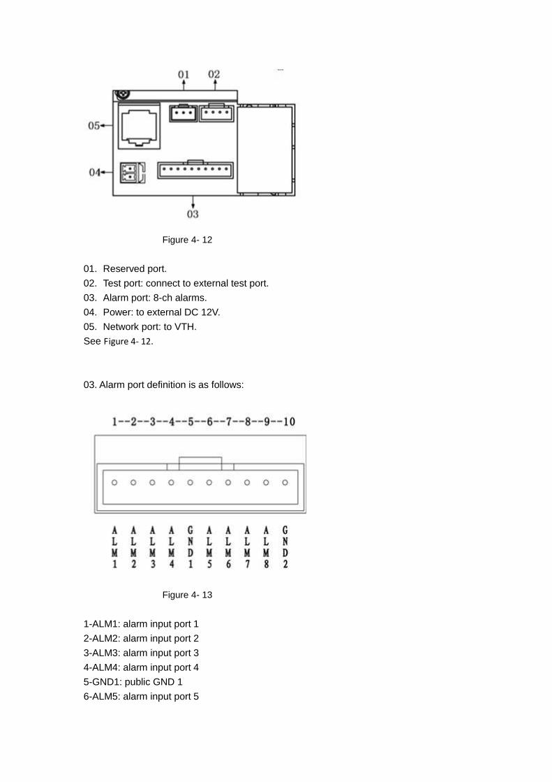
Figure 4- 12
01. Reserved port.
02. Test port: connect to external test port.
03. Alarm port: 8-ch alarms.
04. Power: to external DC 12V.
05. Network port: to VTH.
See Figure 4- 12.
03. Alarm port definition is as follows:
Figure 4- 13
1-ALM1: alarm input port 1
2-ALM2: alarm input port 2
3-ALM3: alarm input port 3
4-ALM4: alarm input port 4
5-GND1: public GND 1
6-ALM5: alarm input port 5
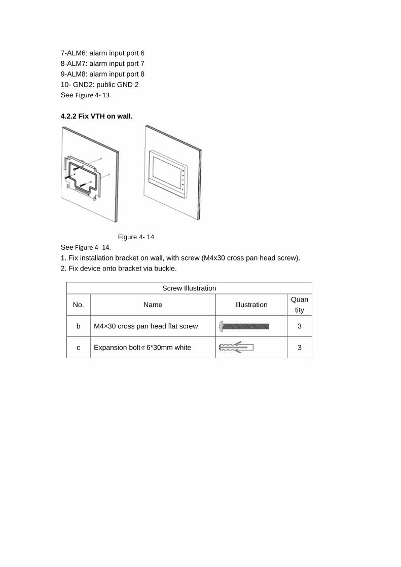
7-ALM6: alarm input port 6
8-ALM7: alarm input port 7
9-ALM8: alarm input port 8
10- GND2: public GND 2
See Figure 4- 13.
4.2.2 Fix VTH on wall.
Figure 4- 14
See Figure 4- 14.
1. Fix installation bracket on wall, with screw (M4x30 cross pan head screw).
2. Fix device onto bracket via buckle.
Screw Illustration
No. Name Illustration Quan
tity
b M4×30 cross pan head flat screw
3
c Expansion bolt¢6*30mm white
3

Figure 4- 15
1. Use screw a to fix bracket ② onto 120 box ③.
2. Use screw b to fix bracket ② onto wall ④.
3. Face rear installation slot to slot on bracket. Make it against wall and push lightly
downward until it is plugged into slot on bracket.
4. Remove: Insert small screwdriver into hole on device ①, and push device upward
until removed.
See
Figure 4- 15.
Screw Illustration
No. Name Illustration Quantity
a M4×30 Cross recessed pan head screws
2
b ST3×18 Cross recessed pan head tapping screws -
white alloy 4
c Expansion pipe ¢6*30mm white
4
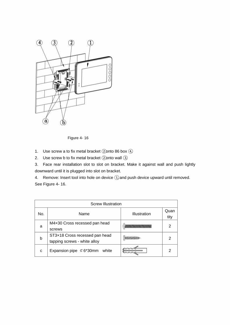
Figure 4- 16
1. Use screw a to fix metal bracket ② onto 86 box ④.
2. Use screw b to fix metal bracket ② onto wall ③.
3. Face rear installation slot to slot on bracket. Make it against wall and push lightly
downward until it is plugged into slot on bracket.
4. Remove: Insert tool into hole on device ①, and push device upward until removed.
See Figure 4- 16.
Screw Illustration
No. Name Illustration Quan
tity
a M4×30 Cross recessed pan head
screws 2
b ST3×18 Cross recessed pan head
tapping screws - white alloy 2
c Expansion pipe ¢6*30mm white
2

4.3 Test
When installation is complete, plug VTO and switch to power, and wait about 2 min until
VTO and VTH boot up. Log in web interface of VTO.
4.3.1 VTO WEB Config:
In web, input VTO IP and input account/password: admin/admin. Then Go to Local Config
and set Video Format to WVGA. See Figure 4- 17.
Figure 4- 17
Go to System Time, click on Sync PC and click on OK. See Figure 4- 18.
Figure 4- 18
Go to Indoor Station Manager, click on Add to add one VTH room no, such as: 102.
Note: VTH Short No. will be automatically generated by the system. See Figure 4- 19.

Figure 4- 19
Go to LAN Config, check Group Call, then click on OK. Reboot VTO. See Figure 4- 20.
Figure 4- 20
Under group call, VTH is classified into main VTH, extension. There can have a maximum
of 1 main VTH and 5 extensions.
4.3.2 Main VTH Setup
Enter Project Settings of main VTH (password 002236)- Product Info, set Room No.,
Local IP, Subnet Mask, Gateway and etc. Input main VTO IP in Network. See Figure 4- 21
and Figure 4- 22.

Figure 4- 21
Figure 4- 22
4.3.3 Extension Setup
The operation is the same as in Main VTH Setup. Enter Project Settings of extension -
Product Info, click on Master button to switch to extension. For example, set room no. to
102-1. Input master IP in corresponding field. When you are done, extension will sync call
info with main VTH’s VTO. See Figure 4- 23.

Figure 4- 23

Appendix Toxic or Hazardous Materials or Elements
Component
Name
Toxic or Hazardous Materials or Elements
Pb Hg Cd Cr VI PBB PBDE
Circuit Board
Component ○ ○ ○ ○ ○ ○
Device Case
○
○ ○ ○ ○ ○
Wire and Cable
○
○ ○ ○ ○ ○
Packing
Components ○ ○ ○ ○ ○ ○
Accessories ○ ○ ○ ○ ○ ○
O: Indicates that the concentration of the hazardous substance in all homogeneous
materials in the parts is below the relevant threshold of the SJ/T11363-2006 standard.
X: Indicates that the concentration of the hazardous substance of at least one of all
homogeneous materials in the parts is above the relevant threshold of the
SJ/T11363-2006 standard. During the environmental-friendly use period (EFUP) period,
the toxic or hazardous substance or elements contained in products will not leak or mutate
so that the use of these (substances or elements) will not result in any severe
environmental pollution, any bodily injury or damage to any assets. The consumer is not
authorized to process such kind of substances or elements, please return to the
corresponding local authorities to process according to your local government statutes.
Note:
This manual is for reference only.
All the designs and software here are subject to change without prior written
notice.
All trademarks and registered trademarks are the properties of their respective
owners.
If there is any uncertainty or controversy, please refer to the final explanation of
us.
Please visit our website for more information.