Embed Size (px)
Citation preview
180544B_MHW_DIGISTAR II - DIGISTAR II Control - GF-BOX_02-2013_ENG
DIGISTAR II / DIGISTAR II Control / GF_BOX
code 80544B / Edition 03 - 02-2013
INSTALLATION AND OPERATION MANUAL
GENERAL INDEX
1 Introduction 32 Installation 53 Functions 84 Connections 9
5 CMOS setup BIOS Phoenix Award 356 Technical characteristics 427 Technical-Commercial information 43
Graphic symbols usedTo distinguish between the type and importance of the information provided in these instructions for use, graphic symbols have been used as a reference to make interpreting the information clearer.
Indicates the contents of the various manual sections, the general warnings, notes, and other points to which the reader’s attention should be drawn.
Indicates a particularly delicate situation that could affect the safety and correct working operation of the controller, or a rule that must be strictly obser-ved to avoid dangerous situations
Indicates a condition of risk for the safety of the user, due to the presence of dangerous voltages at the points shown
Indicates a suggestion based on the experience of the GEFRAN Technical Staff, which could prove especially useful under given circumstances
Information of a general and applicative nature
Important notes for the safety and reliability of the product.
Indicates a reference to Detailed Technical Documents available on the GEFRAN web site www.gefran.com

2 80544B_MHW_DIGISTAR II - DIGISTAR II Control - GF-BOX_02-2013_ENG
Gefran S.p.A. All Rights Reserved
This publication is the exclusive property of GEFRAN spa.The information contained in this document is private and confidential, no part of this document may be repro-duced, photocopied, transmitted, written, translated into other languages, using computer systems or any other electronic, mechanical, optical, chemical, manual or other means, without the specific written agreement of Gefran S.p.A
IMPORTANT
Even though all of the information contained in this document has been carefully checked, Gefran S.p.A. has no responsibility with regards to the presence of mistakes or damages to people or things due to an incorrect use of this manual, the same goes for the people or companies involved in the creation or production of this manual.Furthermore, Gefran S.p.A. reserves the right to bring about changes to the contents and to the appearance of this document, as well as to product specifications, at any time and without any warning.Gefran S.p.A. does not provide any guarantee of any kind related to this material, including but not limited to, the specific warranties of saleability and suitability for a specific objective.Gefran S.p.A. declines any responsibility related to the use of its software on equipment not provided by Gefran S.p.A.
PREFACE
The objective of this document is to provide a detailed description of the main technical characteristics of the har-dware and firmware of the Gefran product called DIGISTAR II and GF-BOX.Information necessary for a correct use of the products to which the manual refers follows. Such information is related to the pinout of connectors with relative signals, setup of bridges and connections with external devices.The majority of the hardware options can be configured by software through the set up data stored in the Eeprom, therefore there are very few pure hardware options, which simplifies remarkably the configuration of the module itself.
Package contents GEFRAN provides the following standard products with DIGISTAR II, DIGISTAR II Control and GF-BOX:• E.M.I. suppressor with ferrite core • Power supply connector • Panel fastening kit• Instruction manual

380544B_MHW_DIGISTAR II - DIGISTAR II Control - GF-BOX_02-2013_ENG
1 • INTRODUCTION
DIGISTAR II and DIGISTAR II Control are industrial PCs with highly scalable functions and resources. They are suitable for many industrial applications, from data centralization systems to plant supervisor, as well as traditional HMI. The Control version can also be used as a machine control unit. This version combines typical functions of a PC architecture with functions expressly created for control applications, such as use of the VxWorks operating system with Seven programming environments, all in a compact frame. Equipped with TFT display (10.4” with 800x600 pixel resolution, 12.1” with 800x600 pixel resolution, and 15” with 1024x768 pixel resolution), they can be completed with a resistive touch screen to facilitate selection and input procedures. DIGISTAR II and DIGISTAR II Control are equipped with an Intel™ processor; choices include Pentium Celeron™ 600 MHz, Celeron Mobile™ 1500 MHz.The special system architecture, based on ETX standard, keeps the product constantly in step with technological advances. All of the processors are low voltage and do not need cooling fans. DIGISTAR II and DIGISTAR II Control can be equipped with DOM solid state mass memory (or 2.5” HD in the Control version) for better configuration based on the application and operating system used. Thanks to a complete series of ports, such as Ethernet, USB, serial, parallel, PS/2 etc., DIGISTAR II and DIGISTAR II Control can connect to the many different peripherals used by industry. An extremely high level of connectivity is obtained by adding optional custom interfaces and standard PCI (not available on the Control version) and PC104 expansion slots. Available interfaces include those for CAN and the expansion for RS422/485 serial lines for Modbus.Some functions on the DIGISTAR II Control, such as keyboard matrix management, LEDs, and timed autostart logic output, are typical of machine or industrial line control. Careful construction and mechanical design ensure easy installation, correct access to DIGISTAR II and DIGISTAR II Control expansions, and correct maintenance to guarantee long life and reliability. DIGISTAR II is available with Microsoft™ Windows™ XP Professional™ Multilanguage (MUI Pack) or Microsoft™ Windows™ XP Embedded™ (English) on solid state disk.DIGISTAR II Control is available with the VxWorks operating system on solid state disk.
DIGISTAR II and DIGISTAR II Control = Industrial PC panel with 10.4”, 12.1” and 15” display

4 80544B_MHW_DIGISTAR II - DIGISTAR II Control - GF-BOX_02-2013_ENG
GF-BOX is a highly scalable industrial PC in terms of functions and resources. In particular the typical functions of a PC architecture have been integrated together with some fun-ctions specifically created for control applications, in a compact case.The characteristics of GF-BOX allow for it to be used in numerous industrial applications, from the machine control unit, to the data centralization system. GF-BOX can also be fitted with a remote display up to 25 m.GF-BOX is equipped with an Intel™ processor; choices include Pentium Celeron™ 600 MHz, Celeron Mobile™ 1500 MHz or Pentium Mobile™ 1800 MHz. The special architecture of the system, based on the ETX standard allows for constant adaptation of the product to technological development.All of the processors are of a low voltage and low consumption and do not require specific cooling fans and allow for GF-BOX to be used even in heavy duty environments.GF-BOX can be fitted with a solid state mass memory of a DOM type or a 2.5” HD for better configura-tion according to the application and the operative system used.Thanks to the complete range of ports available such as Ethernet, USB, serial, parallel, PS/2 etc, GF-BOX can be located in different peripherals that can now also be found in an industrial field. If optional per-sonalized interfaces and standard expansion slots PC1, PC104 are added to them, an extremely large level of connectivity is achieved. The interfaces available include CAN and expansions for serial lines RS422/485 for Modbus.Some functional characters such as handling of the keyboard matrix, leds and logical output of the auto-matic timed switch are typical of the machine control or of industrial lines.The attention given to construction and mechanics allow the user to carry out easy installation, correct access to the GF-BOX expansions and correct maintenance of the product itself in order to guarantee duration and reliability along time.
GF-BOX = internal industrial PC with remote video up to 5 m

580544B_MHW_DIGISTAR II - DIGISTAR II Control - GF-BOX_02-2013_ENG
DIGISTAR II: MECHANICAL CHARACTERISTICS AND DIMENSIONS
2 • INSTALLATION AND CONNECTION
DIGISTAR II 10,4”
275
280
115,
16
212
239
121,
1
309
DIGISTAR II 12,1”
298,91
303
264
294,
511
0,1
6
116,
1
333

6 80544B_MHW_DIGISTAR II - DIGISTAR II Control - GF-BOX_02-2013_ENG
DIGISTAR II: MECHANICAL CHARACTERISTICS AND DIMENSIONS
DIGISTAR II 15”
361,3
365
110,
96
307
337
116,
9
395,3
DIGISTAR II : INSTALLATION AND FIXING SYSTEM
The installation system is the same for both 10,4”, 12.1”,15” DIGISTAR II and DIGISTAR II Control with display versions.
After having carried out the housing according to the template indicated in the drawing, insert the DIGISTAR II from the front, prepare the relative fixing blocks into the respective housings and screw down.

780544B_MHW_DIGISTAR II - DIGISTAR II Control - GF-BOX_02-2013_ENG
MECHANICAL CHARACTERISTICS AND DIMENSIONS INSTALLATION AND FIXING SYSTEM
After having carried out the cuts on the plate as indicated in the template drawing, screw GF-BOX using the screws provided.
Carry out installation of the system by putting the air outlet at the top as shown in the drawing.
The connections of external resources are available at the bottom and through standard connectors.
The resources available are the same for the DIGISTAR II and GF-BOX.
INSTALLATION
Do not install the product within equipment or boxes that do not have suitable air circulation or a thermal exchange that can maintain the temperature below the maximum temperature of the various models.Check to make sure that the air passage ways are not obstructed: keep the inward and outward air filters clean at all times
When installing the product pay special attention to the position of the same in order to avoid any possi-ble accidental knocks.
GF-BOX

8 80544B_MHW_DIGISTAR II - DIGISTAR II Control - GF-BOX_02-2013_ENG
3 • FRONT PANEL: DIGISTAR IIThe functions of the DIGISTAR II and DIGISTAR II Control front panel are the same for the 12.1” and 15” models.
Personalized LOGO pocket
ENTER keyTAB key F1 to F10 keys
Green Led: BUTTON PRESSED
Yellow Led: POWER
Red Led: BATTERY FAIL Green Led: RUN
Green Led: AUX
Green Led: HD
It is also possible to have the front panels with 5 wire resistive Touch Screen.

980544B_MHW_DIGISTAR II - DIGISTAR II Control - GF-BOX_02-2013_ENG
EXTERNAL USER CONNECTIONS (1) Standard mouse plug PS2 (2) AT keyboard plug (3) 2 USB connectors (type A) (4) ethernet output 10/100 bsp, standard RJ45 (5) ON/OFF power switch (6) Standard VGA switch (7) Matrix keyboard and Led connection, connection (GT-TAST interface) (8) External battery connection 3.6V (9) Power connection and external fan plug (10) Automatic switch connector (11) COM 1 standard serial
(12) COM 2 standard serial (13) Centronics parallel connection (14) External floppy disk connection with integrated supply (15) GT-ETH board expansion slot (16) GT-SER 2 board expansion slot (17) GT-CAN board expansion slot (18) PCI expansion slot (19) Monitoring led (20) AUX slot, auxiliary connection
10 9 7 6 4 3
2
1
11 1213
14820 5
181615 1917
(details of user connection)
By opening the cover of DIGISTAR II you can access the control electronics and some internal resources. For installation and the use of internal resources refer to the technical manual.
4• CONNECTIONS

10 80544B_MHW_DIGISTAR II - DIGISTAR II Control - GF-BOX_02-2013_ENG
PS/2 mouse and keyboard (1) and (2)2 connectors and 6 minidin poles are provided for external keyboard and mouse
DESCRIPTION OF THE CONNECTIONS OF USER RESOURCES
KEYBOARDPin number MOUSE
SignalKBD DATA
N.C.GND5 VDc
KBD CLKN.C.
FunctionKeyboard Data
N.C.GND Power
+ 5 VoltsKeyboard Clock
N.C.
SignalMS DATA
N.C.GND5 VDc
MS CLKN.C.
FunctionMouse Data
N.C.GND Power
+ 5 VoltsMouse Clock
N.C.
123456
Accessories and expansions such as keyboards (DIGITAST) and remote displays (DIGIPANEL) are availabe to complete the DIGISTAR II, DIGISTAR II Control and GF-BOX products.The DIGITAST + Touch-Pad keyboard can be connected to the DIGISTAR II via two PS/2 interfaces (Keyboard and Mouse).The DIGIPANEL+Touch-Screen remote display can be connected to the DIGISTAR II via a VGA interface.
Connection with DIGITAST and DIGIPANEL
VGAPS/2 Mouse
PS/2 Keyboard
DIGIPANEL
DIGITAST
GF-BOX

1180544B_MHW_DIGISTAR II - DIGISTAR II Control - GF-BOX_02-2013_ENG
USB (3)The USB connection includes 2 slot masters, a type A connector with 4 poles. It is also possible to connect two users at the same time.
USB Pin number Signal 1 VCC_USB 2 USB1- 3 USB1+ 4 GND_USB 5 VCC_USB 6 USB2- 7 USB2+ 8 GND_USB
ETHERNET (4)The RJ45 ethernet connection complies with standards TIA/EIA-568-A with a transmission speed of 10/100 Mbps.
For connections, use a cable of adequate category to the application. In an industrial environment the category 6 cable is recommended.
ETHERNET 10/100 BASET Pin number Signal 1 TX+ 2 TX- 3 RX+ 4 N.C. 5 N.C. 6 RX- 7 N.C. 8 N.C. Green led on the left data Yellow led on the right link

12 80544B_MHW_DIGISTAR II - DIGISTAR II Control - GF-BOX_02-2013_ENG
Power switch (5)In order to start the system turn the switch to the ON position.
The presence of power to the system is indicated by the relative power led (see leds for identification).
CRT VGAPin number Signal 1 RED 2 GREEN 3 BLUE 4 N.C. 5 GND 6 AGND 7 AGND 8 AGND 9 N.C. 10 GND 11 N.C. 12 N.C. 13 HSYNC 14 VSYNC 15 N.C.
Video (6)Analogue output for SVGA standard video. Connection by DB15 high density connector.
Use a video cable of a standard kind not longer than 5 metres.
1380544B_MHW_DIGISTAR II - DIGISTAR II Control - GF-BOX_02-2013_ENG
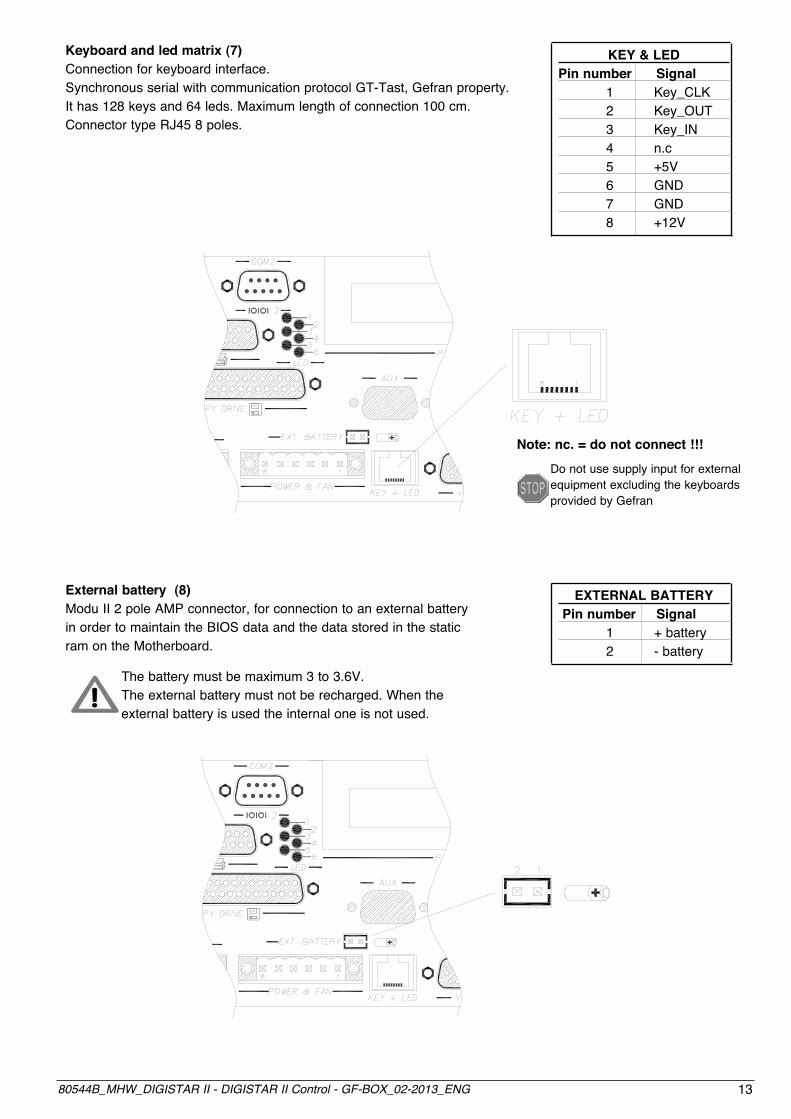
Keyboard and led matrix (7)Connection for keyboard interface. Synchronous serial with communication protocol GT-Tast, Gefran property.It has 128 keys and 64 leds. Maximum length of connection 100 cm. Connector type RJ45 8 poles.
KEY & LEDPin number Signal 1 Key_CLK 2 Key_OUT 3 Key_IN 4 n.c 5 +5V 6 GND 7 GND 8 +12V
EXTERNAL BATTERY Pin number Signal 1 + battery 2 - battery
External battery (8)Modu II 2 pole AMP connector, for connection to an external battery in order to maintain the BIOS data and the data stored in the static ram on the Motherboard.
The battery must be maximum 3 to 3.6V. The external battery must not be recharged. When the external battery is used the internal one is not used.
Note: nc. = do not connect !!!Do not use supply input for external equipment excluding the keyboards provided by Gefran

14 80544B_MHW_DIGISTAR II - DIGISTAR II Control - GF-BOX_02-2013_ENG
6 1
24V
500mA MAX
+24Vcc ± 20%
2.5A max
GND +24V
+-
- - + +
Self-start output (10)Connection for activation of an external relay according to an internal programmable timer.
In order to activate the relay it is sufficient to provide power to it. Use the free contact of the relay to acti-vate external equipment. The timed relay will stay on for approximately 10 seconds.
Use a 24 Vcc relay with 100mA maximum rating.
+24VDC
GND
Power supply (9)To limit susceptibility to interference, an electromagnetic emission suppresser core has to be installed as shown in the Figure. This component (supplied with the product), is a ferrite core contained in plastic for round section wires. 24Vcc 2.5A max (18-36Vcc) power supply, the internal power supply is insulated by galvanisation and protected from polarity inversions and short circuits with a re-settable fuse. Output for 24Vcc 200mA max fan.
The fan control is regulated by a thermostat, therefore the fan starts when the internal temperature exceeds 35°C.

1580544B_MHW_DIGISTAR II - DIGISTAR II Control - GF-BOX_02-2013_ENG
Serial port COM1 (11)Male DB9 connector. The serial line on COM1 can be configured in RS232, RS422, RS485 mode. Configuration is carried out by moving the relevant dip switches according to the table provided below.
In order to access the dip switch, open the rear cover on DIGISTAR II or on GF-BOX, see specificparagraph.
The serial configured in RS422 is opto-insulated.The serial configured in RS485 is opto-insulated.n.c. = do not connect
TABLE MODE COM1:
123456789
RS232 RS422 RS485
SignalDCDRXTX
DTRGNDDSRRTSCTSRI
FunctionData Carrier Detect
Receive DataTrasmit Data
Data Terminal ReadySignal Ground
Data Set ReadyRequest To Send
Clear To SendRing
SignalRX-RX+TX+TX-
GND
FunctionReceive Data -Receive Data +Transmit Data +Transmit Data -
Ground n.c.n.c.n.c.n.c.n.c.
Signal
TX+/RX+
TX-/RX-GND
Function
DATA+
DATA-Ground n.c.
Nr. Pin

16 80544B_MHW_DIGISTAR II - DIGISTAR II Control - GF-BOX_02-2013_ENG
Reception can be configured as always enabled or controlled by the software through the signal. Transmission can always be controlled by software through the RTS signal, that activates or prevents the transmitter to control a multi point line with more than one competitor.
TABLE CONFIGURATION COM 1 SERIAL
Dip S1-1Dip S1-2Dip S1-3Dip S1-4Dip S1-5Dip S1-6Dip S1-7Dip S1-8
Dip S2-1Dip S2-2Dip S2-3Dip S2-4Dip S2-5Dip S2-6Dip S2-7Dip S2-8
Dip S5-1Dip S5-2
Dip S2-7Dip S2-8Dip S5-7Dip S5-8
Dip S5-3Dip S5-4Dip S5-5Dip S5-6
RS232 RS422 RS485
ONONONONON
-ON
-
OFFOFFOFFOFFOFFOFFOFFOFF
OFFOFF
OFFOFFOFFOFFOFF
-OFF
-
ONONONONONON
See polarization tableSee polarization table
OFFOFF
OFFOFFOFFOFFOFF
-OFF
-
ONONONONONON
See polarization tableSee polarization table
ONON
Polarization and termination TX + active Polarization and termination TX - active Polarization and termination RX + active Polarization and termination RX - active
Software managed through RTS RTS managed through TX
Reception managed like RTS Always qualified reception
Polarization and Termination
Managed through RTS

1780544B_MHW_DIGISTAR II - DIGISTAR II Control - GF-BOX_02-2013_ENG
CONFIGURATION FOR SERIAL COM1

18 80544B_MHW_DIGISTAR II - DIGISTAR II Control - GF-BOX_02-2013_ENG
Serial Port COM2 (12)9 pole male connector standard serial COM2. The serial is provided in RS232 standard.
FunctionData carrier detect
Receive DataTrasmit Data
Data terminal readySignal GroundData set ready
Request To SendClear To Send
Ring
Nr Pin123456789
SignalDCDRXTX
DTRGNDDSRRTSCTSRI
COM 2 RS232
1980544B_MHW_DIGISTAR II - DIGISTAR II Control - GF-BOX_02-2013_ENG
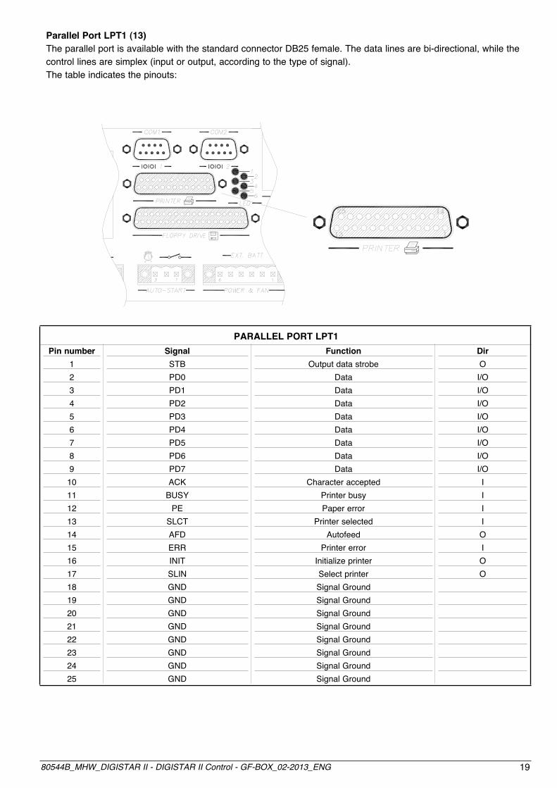
Parallel Port LPT1 (13)The parallel port is available with the standard connector DB25 female. The data lines are bi-directional, while the control lines are simplex (input or output, according to the type of signal).The table indicates the pinouts:
PARALLEL PORT LPT1Pin number
12345678910111213141516171819202122232425
DirO
I/OI/OI/OI/OI/OI/OI/OI/OIIIIOIOO
SignalSTBPD0PD1PD2PD3PD4PD5PD6PD7ACK
BUSYPE
SLCTAFDERRINITSLINGNDGNDGNDGNDGNDGNDGNDGND
FunctionOutput data strobe
DataDataDataDataDataDataDataData
Character acceptedPrinter busyPaper error
Printer selectedAutofeed
Printer errorInitialize printerSelect printerSignal GroundSignal GroundSignal GroundSignal GroundSignal GroundSignal GroundSignal GroundSignal Ground

20 80544B_MHW_DIGISTAR II - DIGISTAR II Control - GF-BOX_02-2013_ENG
Floppy Disk Interface (14)Connection to an FDD is available through a DB37 female connector according to the layout defined in the following table.
The connector provides power supply of 5V for the FDD.
CONNECTORPin number
12345678910111213141516171819
SignalGNDN.C.GNDGNDGNDGNDGNDGNDGNDGNDGNDGNDGNDGNDGNDGNDGNDGNDN.C.
SignalDENSEL
N.C.N.C.
INDEXMTR0DRV1DRV0MTR1DIR
STEPWDATAWGATETRKO
WRPRTRDDATAHDSEL
DSKCHGVCC (+5V)
Pin number202122232425262728293031323334353637

2180544B_MHW_DIGISTAR II - DIGISTAR II Control - GF-BOX_02-2013_ENG
Led Diodes (19)On the back of the module, the leds indicate the machine status.
Led UBI Colour Function 1 Red Over-temperature 2 Green Connection to key- board and led matrix 3 Green Auxiliary 4 Green RUN 5 Yellow POWER 6 Red BATTERY FAIL
REMOTE VIDEO output (GF-BOX ONLY)GF-BOX can be fitted with optional video and keyboard remoting.The remoting system allows the DIGIPANEL and GT_O display to be connected up to a distance of 25 m.
The electrical connection must be made using the Gefran prewired cable (see specific document) or by following the constructive specifications of the cable.

22 80544B_MHW_DIGISTAR II - DIGISTAR II Control - GF-BOX_02-2013_ENG
Before opening the system we recommend that you switch off Digistar II, DIGISTAR II Control or GF-BOX using the ON/OFF switch provided.
In order to access the internal resources of the system, a flat blade screwdriver is required.
ACCESS TO THE INTERNAL RESOURCES OF THE SYSTEM
In order to open the rear cover insert the screwdriver into the slots A and B, apply some pressure in the direction indicated by the arrow.
Expansions and internal resources
(1) PCI standard slot (2) PC104 standard slot (3) Battery (4) Battery switch (5) IDE secondary 40 pin connector (6) IDE primary 44 pin connector (HD and DOM installation) (7) Serial COM1 configuration (8) 4 slot expansion custom gefran

2380544B_MHW_DIGISTAR II - DIGISTAR II Control - GF-BOX_02-2013_ENG
Mass memoryThe motherboard contains a 44 pole 2mm pitch connector and a 40 pole 2.54mm pitch connector upon which signals are provided for a 2.5” hard disk and/or a solid disk with an IDE AT interface compatible type Disk On Module (DOM).It is possible to install hard disks of any capacity, in compliance with these standards.The 44 pin connector is mapped as an IDE PRIMARY interface, use this to install the hard disk or the DOMs. The 40 pin connector is mapped as an IDE SECONDARY interface, use this for expansion chains, such as CDs for example.The product is normally provided complete with DOM or HD in compliance with order code.
Installation of the DOMTo install or replace the DOM once the system has been opened, insert the module into the relative case, as indicated in the drawing below, respecting the polarity.
INSTALLATION OF A HDGefran provides a kit complete with HD and mechanical support with a connection cable for complete installation of the same.
The HD is installed onto the towers provided for the PC104 module. When PC104 modules are installed, the HD block is always installed as the last.
For installation, insert the HD, correctly mounted onto its support, into the 4 towers and block using 4 screws.Connect the cable provided, respecting the polarities indicated.

24 80544B_MHW_DIGISTAR II - DIGISTAR II Control - GF-BOX_02-2013_ENG
Battery switchThe system is fitted with an internal battery in order to store the BIOS data and the data in the static RAM memory.
The battery must be activated through the switch indicated in the drawing below.
To replace the battery, if necessary, proceed in the following way:
• get hold of a new battery, a button battery diam. 24mm, 3V lithium (CR2430) • switch off the system using the correct switch • position the battery switch to the OFF position • remove the battery and insert the new one • move the battery switch to the ON position • turn the system on.
You have five minutes to change the battery before losing all data.

2580544B_MHW_DIGISTAR II - DIGISTAR II Control - GF-BOX_02-2013_ENG
Installation of PCI boardsThe basic card has one slot for PCI boards The system supports PCI boards with a maximum length of 150mmFor PCI installation:
• Remove the neutral cover.• Install the card by inserting it into the relative electrical and mechanical housings.• Fix the card using the screw provided.• Power the system, when you start Access
the CMOS system SETUP (as described in the following paragraphs) and, in the menu “PNP/PCI Configuration”, enable the “Reset Configuration Data”
• Turn on the system and install any drivers of software provided by the manufacturer of the card
Installation of the PC104 boardsThe motherboard has one slot for PC104 boards with the support towers already installed.To install the card, insert it into the relative electrical and mechanical housings.Fix the card using 4 towers, or if necessary 4 3ma nuts.
Any input/output must be installed using the spaces provided for the customs slots.
Turn on the system and install any drivers or software provided by the manufacturer of the card.

26 80544B_MHW_DIGISTAR II - DIGISTAR II Control - GF-BOX_02-2013_ENG
Installation of Gefran CUSTOM boardsThe motherboard has 4 custom slots for the installation of further resources.To install the custom boards:• Remove the neutral cover• Install the card by inserting it into the relative electric and mechanical housings• For installation of specific cards; consult the appropriate pages in the relevant handbook• Fix the card using the screws in the holes provided.

2780544B_MHW_DIGISTAR II - DIGISTAR II Control - GF-BOX_02-2013_ENG
GT-SER 2SERIAL COMMUNICATION MODULE
Main applications• ConnectionofGefranindustrial PCstoRS-232,RS-485,RS-422network
Main characteristics• Configurableoptically-isolatedserial ports• Selectableinterfaces:RS-232,RS-485, RS-422• COM3connector:D-Sub9pinmale• COM4connectors:RJ10• Highcommunicationspeed:from 9.6kBaudto115kBaud
PROFILEGT-SER2isaserialbusexpansionmoduleforindustrialPCsandforDigistarIIandGT-Ccontroltermi-nals.Itprovides2opticallyisolatedserialchannelsprotectedagainstovervol-tages.ItperformscontrolandinterfacesthecommunicationnetworkwithRS-232,RS-485,RS-422standards,selecta-blewithDIP-Switches.TheserialconnectionusesaD-Sub9pinmaleconnectorforCOM3andanRJ104pinconnectorforCOM4.IntheDigistarII,GT-CandGFBOXterminals,theexpansionmoduleinsertsintheexpansion2customslot(EXP2).
TECHNICAL DATA
• 2 configurable optically-isolated serial ports• DIP-Switches to configure RS-232, RS-485, RS-422 and to enable automa- tic transmission/reception and from software via dip-switch• Connectors: COM3 D-Sub 9 pin male, COM4 RJ10 4 pin• High communication speed: from 9.6 kBaud to 115 kBaud • Configurable terminations and polarisa- tions
Mechanical characteristics
• Dimensions: 60x20x80 mm• Weight (*): 51g (including anti-static bag supplied as standard)• Fastening: screw• Connector for connection to Gefran industrial PCs
aMbient conditions
• Working temperature: 0…50°C• Storage temperature: -20…70°C• Humidity: 90% RH max., non-condensing
Installation and Connections
The GT-SER 2 expansion module installs in Gefran Digistar II, GT-C and GF-BOX industrial PCs in slot EXP 2.

28 80544B_MHW_DIGISTAR II - DIGISTAR II Control - GF-BOX_02-2013_ENG
INSTALLATION and CONNECTIONS
J10
(COM4)
J2
(COM3)
J10
(COM4)
1 5
96
1 4
10 9
2 1
J2
(COM3)
J10
(COM4)
J10
(COM4)
DB-9 connector: Serial COM3
PIN RS-232 RS-422 RS-4851 DCD RX- RX- / TX-2 RXD RX+ RX+ / TX+3 TXD TX+ RX+ / TX+4 DTR TX- RX- / TX-5 GND GND GND6 DSR 7 RTS 8 CTS 9 RI
2x5 connector: Serial COM4
PIN RS-232 RS-422 RS-4851 DCD RX- RX- / TX-2 DSR 3 RXD RX+ RX+ / TX+4 RTS 5 TXD TX+ RX+ / TX+6 CTS 7 DTR TX- RX- / TX-8 RI 9 GND GND GND10 GND GND GND
RJ-10 connector: Serial COM4
PIN RS-232 RS-422 RS-4851 GND GND2 RXD NOT RX+ / TX+3 TXD USED RX- / TX-4 RTS VCC
COM4 on the RJ10 connector is limited to signals TX and RX. Full functionality of COM4 can be restored via the adapter cable.

2980544B_MHW_DIGISTAR II - DIGISTAR II Control - GF-BOX_02-2013_ENG
Connector typeD-SUB 9 pin Male FLAT10 pin FLAT cable
Connector
10 pin female FLAT
2
10
1
5
6
9
J1
(COM4)
J2
(COM4)
J3
S15
S10
S9
S8S25
S14
S11 S13
J4
(COM4)
S15 (COM3)Pin Value Description 1 ON Polarisation + Present OFF Polarisation + Absent 2 ON Termination Present OFF Termination Absent 3 ON Polarisation + Present OFF Polarisation + Absent 4 ON Polarisation + Present OFF Polarisation + Absent 5 ON Termination Present OFF Termination Absent 6 ON Polarisation + Present OFF Polarisation + Absent
Rec
eptio
n
T
rans
mis
sion
S25 (COM4)Pin Value Description 1 ON Polarisation + Present OFF Polarisation + Abesent 2 ON Termination Present OFF Termination Absent 3 ON Polarisation + Present OFF Polarisation + Absent 4 ON Polarisation + Present OFF Polarisation + Absent 5 ON Termination Present OFF Termination Absent 6 ON Polarisation + Present OFF Polarisation + Absent
Rec
eptio
n
T
rans
mis
sion
Note: Terminations and polarisations must be installed only at the heads of the line.

30 80544B_MHW_DIGISTAR II - DIGISTAR II Control - GF-BOX_02-2013_ENG
Selection COM3 SWITCH PIN RS-232 RS-485 RS-422
9 All ON OFF OFF 10 All OFF ON ON 8 1 and 2 X ON OFF
Selection COM4 SWITCH PIN RS-232 RS-485 RS-422
13 All ON OFF OFF 11 All OFF ON ON 14 1 and 2 X ON OFF
Methods to enable Transmission/Reception in RS232/RS485/RS422
Configurations S8 (COM3)
Pin Value Description 3 OFF Auto-enable Transmission and Reception 4 ON 5 ON Reception enabled from RTS 6 OFF
Configurations S14 (COM4)
Pin Value Description 3 OFF Auto-enable Transmission and Reception 4 ON 5 ON Reception enabled from RTS 6 OFF 8 ON COM4 disabled 8 OFF COM4 enabled
Attention:the electronic base uses COM4 for the touch controller. If installed, do not enable the corresponding serial on GT-SER 2.
GEFRAN reserves the right to make any kind of design or functional modification at any moment without prior notice
GT-SER2 F029908
ORDER CODE
Code module Code2 SERIAL channels

3180544B_MHW_DIGISTAR II - DIGISTAR II Control - GF-BOX_02-2013_ENG
GT-CAN 1 / GT-CAN 2CAN COMMUNICATION MODULES
Main applications• ConnectionofGefran DIGISTARII,GT-CandGF-BOX industrialPCstoaCAN-bus network
Main characteristics • Optically-isolatedCANchannels• Removable3x2pinfemaleconnector withspringclamp(noscrews)• ConformstostandardCAN2.0(b)
PROFILEGT-CAN1andGT-CAN2areexpan-sionmodulestoCANfieldbusesdedicatedtoGefranDIGISTARII,GT-CandGF-BOXindustrialPCs.Theysupply1and2optically-isolatedCANchannels,respectively,andinterfacethefieldbusinconformityto2.0(b)specifications.Thefieldbusconnectionusesaremovable3x2pinfemaleconnectorwithspringclamp(noscrews).TheexpansionmoduleinsertsinGefranDIGISTARII,GT-CandGF_BOXterminalsinexpansionslots3and4foramaximumof4CANchannels.
TECHNICAL DATA
• GT-CAN 1: 1 Optically-isolated CAN channel• GT-CAN 2: 2 Optically-isolated CAN channels• Channels protected against overcur- rents • Removable 3x2 pin female connector with spring clamp (no screws)• CAN controller CAN: INTEL 82527 (communication speed: up to 1 MBaud, CAN 2.0 (b) specifications)• High immunity to electromagnetic inter- ference
Mechanical characteristics
• Dimensions: 60x20x80 mm• Weight -CAN 1: 45g (including anti-static bag supplied as standard)• Weight GT-CAN 2: 49g (including anti-static bag supplied as standard)• Fastening: screw • Connector for connection to Gefran industrial PCs
aMbient conditions
• Working temperature: 0…50°C• Storage temperature: -20…70°C• Humidity: 90% RH max., non-condensing
Installation and Connections
The GT-CAN 1 and GT-CAN 2 expansion modules install in Gefran Digistar II, GT-C and GF-BOX control terminals in custom expansion slots 3 and 4 for a maximum of 4 CAN channels.

32 80544B_MHW_DIGISTAR II - DIGISTAR II Control - GF-BOX_02-2013_ENG
INSTALLATION and CONNECTIONS
5
3
1
6
4
2
J2
J2
GT-CAN 1
Description
PIN CAN1 (J2) Channel CAN2 (J3**) Channel1 TERMINATION (*) TERMINATION (*)2 TERMINATION (*) TERMINATION (*)3 CANH1 CANH24 CANL1 CANL25 SHIELD SHIELD6 CANGND1 CANGND2
(*) To insert the termination, short circuit pins 1-2: the termination inserts only in the ends of the CAN line.(**) J3 not present in version GT-CAN 1
Connection cablesUse an approved CAN cable for the connection
GEFRAN reserves the right to make any kind of design or functional modification at any moment without prior notice
ORDER CODE
GT-CAN 2 F029826Code module Code2 CAN channels
GT-CAN 1 F029825Code module Code1 CAN channel

3380544B_MHW_DIGISTAR II - DIGISTAR II Control - GF-BOX_02-2013_ENG
GT-ETH 1 / GT-ETH 2ETHERNET COMMUNICATION MODULES
Main applications• ConnectionofGefranindustrial PCstoEthernet
Main characteristics• StandardEthernetchannels• RJ45connectorwithLEDs• Communicationspeed:10/100Mbps• ConformstostandardIEEE802.3
PROFILEGT-ETH1andGT-ETH2expansionmodulestoEthernetnetworksdedi-catedtoGefranindustrialPCs.Theysupply1and2Ethernetchan-nels,respectively,inconformitytostandardIEEE802.3.TheEthernetconnectionusesRJ45connectors.TheexpansionmoduleinsertsinGefranDIGISTARII,GT-CandGF_BOXindustrialPCsincustomexpan-sionslot1(EXP1).
TECHNICAL DATA
• GT- ETH 1: 1 Ethernet channel, not optically isolated• GT- ETH 2: 2 Ethernet channels, not optically isolated • Ethernet controller: INTEL 82551 (Communication speed: 10/100 Mbps auto-configurable)• 8 pin RJ45 connector with Data and Link LEDs
Mechanical characteristics
• Dimensions: 60x20x80 mm• Weight GT-ETH 1: 46g (including anti-static bag supplied as standard)• Weight GT-ETH 2: 53g (including anti-static bag supplied as standard)• Fastening: screw • Connector for connection to Gefran industrial PCs
aMbient conditions
• Working temperature: 0…50°C• Storage temperature: -20…70°C• Humidity: 90% RH max., non-condensing
Installation and Connections
The GT-ETH 1 and GT-ETH 2 expansion modules insert in Gefran DIGISTAR II, GT-C and GF_BOX terminals in custom expansion slot 1 (EXP 1).

34 80544B_MHW_DIGISTAR II - DIGISTAR II Control - GF-BOX_02-2013_ENG
INSTALLATION and CONNECTIONS
*J3 not present in version GT-ETH 1
Connection cableUse an Ethernet Base-T (CAT. 6) cable for the connection. The wiring scheme must conform to standard TIA/EIA-T568-A
J2 1
8
J2
GT-ETH1
LED Link
(Yellow)
LED Data
(Green)
GEFRAN reserves the right to make any kind of design or functional modification at any moment without prior notice
ORDER CODE
GT-ETH 2 F029910Code module Code2 ETHERNET Channels
GT-ETH 1 F029909Code module Code1 ETHERNET Channel
Channel ETH 1 (J2)/ ETH 2 (J3*)
Pin Name Description1 TX_D+ Transmit data +2 TX_D- Transmit data -3 RX_D+ Receive data +4 N.C. Not connected5 N.C. Not connected6 RX_D- Receive data -7 N.C. Not connected8 N.C. Not connected LED green left Data LED yellow right Link
J2 1
J3
8
1
8
J2
J3
GT-ETH2
LED Link
(Yellow)
LED Data
(Green)

3580544B_MHW_DIGISTAR II - DIGISTAR II Control - GF-BOX_02-2013_ENG
5• CMOS SYSTEM SETUP The BIOS setup is used to set the system resources.
GefransuppliesthesystemwiththeBIOSsettingsdefinedforthetypeofhardwareused.Anychangetothesesettingsmustbedoneverycarefullyandbyanexpert,becauseincorrectsettingsmaycausethesystemtomal-function.
Default Settings• Standard CMOS Features/Halt On: [No Errors]• Advanced Chipset Feature/System Reset Times: [2]• Chipset Features Setup/On-Chip VGA/On-Chip Frame Buffer Size: [8MB]• Chipset Features Setup/On-Chip VGA/Boot Display: [CRT+LCD]• Chipset Features Setup/On-Chip VGA/Panel Number: [800x600 18-bit]• Integrated Peripherals/On-Chip IDE Device: [Disable]• Integrated Peripherals/Onboard Device/AC97 Audio: [Disable]• Integrated Peripherals/Onboard Device/Init Display First: [Onboard/AGP]• Integrated Peripherals/Onboard Device/External FDD Controller: [Disabled]• Integrated Peripherals/Onboard Device/Onboard Parallel Port: [Disabled]• Integrated Peripherals/Onboard Device/Onboard FDD Controller: [Disabled]• Integrated Peripherals/Onboard Device/Onboard Serial Port 3: [3E8]• Integrated Peripherals/Onboard Device/Serial Port 3 Use IRQ: [IRQ10]• Integrated Peripherals/Onboard Device/Onboard Serial Port 4: [2E8]• Integrated Peripherals/Onboard Device/Serial Port 4 Use IRQ: [IRQ11]• PnP/PCI Configurations/Resources Controlled By: [Manual]• PnP/PCI Configurations/IRQ Resources/IRQ-5 Assigned to: - [Legacy ISA] (with VxWorks) - [PCI/ISA PnP] (with Microsoft™ Windows™)• PnP/PCI Configurations/IRQ Resources/IRQ-9 Assigned to: - [Legacy ISA] (with VxWorks) - [PCI/ISA PnP] (with Microsoft™ Windows™)
PHOENIX – AwardBIOS CMOS Setup UtilitySetup is accessed by pressing the DEL key at power-on.After this, access the MAIN menu.Methods for setting and selecting parameters are described at the foot of the menus.Once the required item is selected with the ENTER key, the selection of settings is enabled. The BIOS is divided into various menus to optimize configuration of the board. The main menu is divided into the following categories:
• Standard CMOS Features: Basic system configurations.• Advanced BIOS Features: Advanced system features.• Advanced Chipset Features: Access to chipset registers to optimize system performance.• Integrated Peripherals: Settings for peripherals integrated in system CPU.• Power Management Setup: Settings to manage system power.• PnP / PCI Configuration: Present only if the system supports PnP / PCI.• PC Health Status: Monitors system status.• Load Optimized Defaults: Use this menu to load the BIOS default values set in the factory to optimize system performance.

36 80544B_MHW_DIGISTAR II - DIGISTAR II Control - GF-BOX_02-2013_ENG
• Set Password: Sets user and supervisor passwords.• Save & Exit Setup: Saves BIOS settings and exits Setup.• Exit Without Save: Exits Setup without saving BIOS settings.
Standard CMOS Setup
• Date: system date setting (the field for the day of the week cannot be changed by the user: it is defined by the BIOS based on the other date information). • Time: system clock setting.• IDE Primary Master/Slave, IDE Secondary Master/Slave: hard disk parameter settings
A sub-menu is displayed. - Hard Disk sub-menu The AUTO setting seeks and automatically sets the HD parameters installed during the boot phase. You can set the HD parameters manually by activating the USER setting. Parameters are normally available on the product label. After the hard disk is installed, you have to run the partitioning procedures and install the selected operating system.• Drive A, B: selection of drivers of disks installed in system.• Video: selection of type of video system in system• Halt On: setting of hardware error conditions (detected during self-test at system start-up) that cause the system to stop.
BIOS Features Setup
• Virus Warning: VIRUS Warning settings to protect sections of IDE hard disk. • CPU L1 & L2 Cache: enables level 1 and 2 cache.• CPU L3 Cache: enables level 3 cache.• Quick Power On Self Test: quickens self-test procedure at power-on.• First/Second/Third Boot Device: sequence of devices from which BIOS tries to load the operating system (Floppy, LS/ZIP, HDD, SCSI, CDROM, Disabled).• Swap Floppy Drive: swaps the association between driver and logic name (if the system has two floppy drives)• Boot Up Floppy Seek: seeks disks during system boot• Boot Up NumLock Status: NumLock status at system boot.

3780544B_MHW_DIGISTAR II - DIGISTAR II Control - GF-BOX_02-2013_ENG
• Gate A20 Option: selects GateA20 controller from among chipset and keyboard controllers• Typematic Rate Setting: controls the speed and delay with which the system repeats a key kept pressed.• Security Option: : password request at every system boot or only at access to system setup• APIC Mode: selects APIC mode. • OS Select for DRAM > 64MB: selects operating system with more than 64MB of dynamic RAM.• Video BIOS Shadow: enables copy of BIOS video from ROM to RAM.• C8000-CBFFF Shadow: : enables copy of system components firmware in memory segments from C8000 to CBFFF.• Small Logo(EPA) Show: enables display of logo on screen.• EEPROM Write Protect: protects EEPROM memory containing system configuration.
Chipset Features Setup
• DRAM Timing Selectable: timing of dynamic RAM selectable from SPD or manually.• CAS Latency Time: selects number of CAS latency cycles (with synchronous DRAM)• Active to Precharge Delay: delay in addressing to different lines of a memory chip.• DRAM RAS-to-CAS Delay: delay between CAS and RAS strobe signals.• DRAM RAS Precharge: DRAM RAS precharge time.• DRAM Data Integrity Mode: checks ECC characteristics of memory controller.• MGM Core Frequency: MGM core frequency setting ( 400/266/133/200 MHz).• System BIOS Cacheable: enables caching of BIOS in memory zone from F0000h to FFFFFh.• Video BIOS Cacheable: enables caching of Video BIOS.• Memory Hole At 15M-16M: reserves memory area for ROM of ISA adapter.• Delayed Transaction: enables delayed transactions (conformity to standard PCI version 2.1)• Delay Prior to Thermal: selects 4, 8, 16, 32 minutes.• AGP Aperture Size: real size of graphic aperture for a particular GMCH configuration.• On-Chip VGA: enables VGA controller.• On-Chip Frame Buffer Size: selects size of On-Chip Frame Buffer (1MB or 8MB).• Boot Display: selects display device.• Panel Number: selects display resolution
38 80544B_MHW_DIGISTAR II - DIGISTAR II Control - GF-BOX_02-2013_ENG
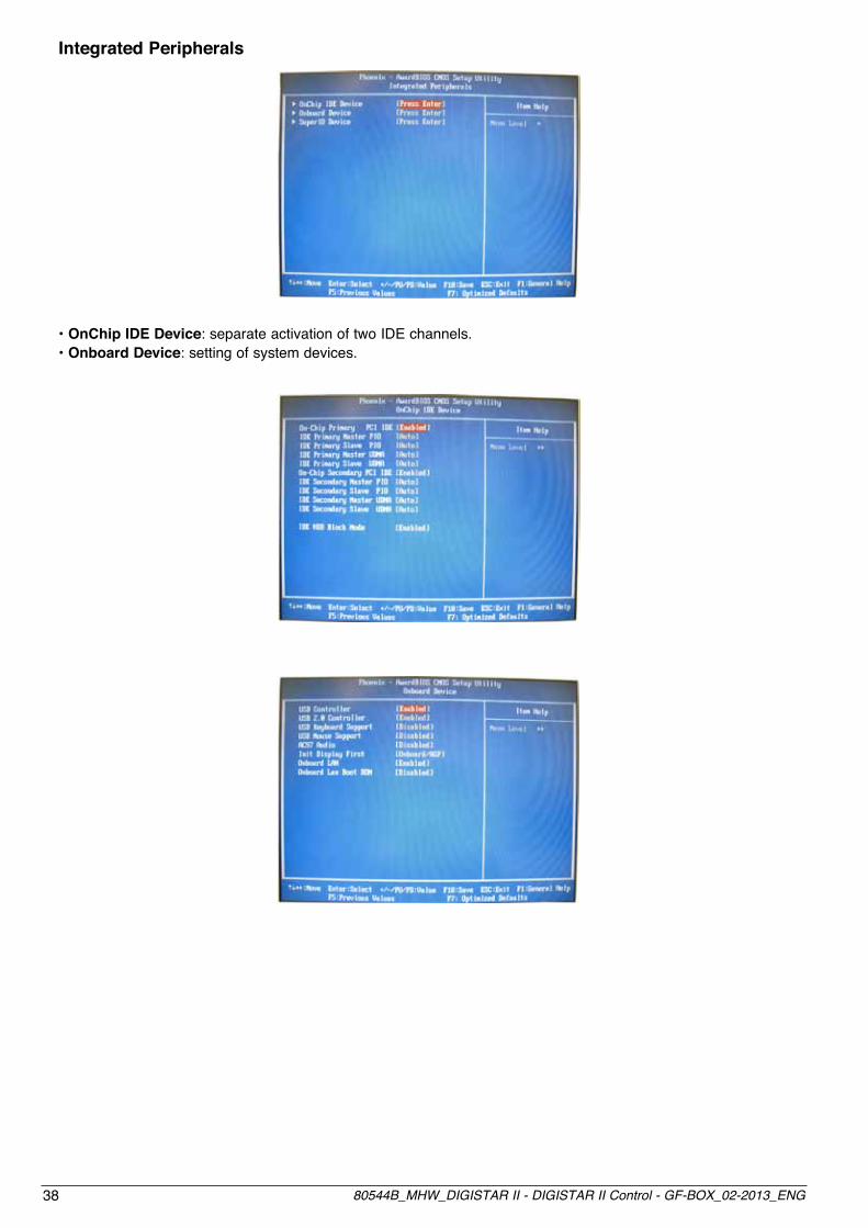
Integrated Peripherals
• OnChip IDE Device: separate activation of two IDE channels.• Onboard Device: setting of system devices.

3980544B_MHW_DIGISTAR II - DIGISTAR II Control - GF-BOX_02-2013_ENG
• Super I/O Device Onboard LAN Boot ROM: reduces system boot time.
Super I/O Device• External FDC Controller: “Enabled” activates on-board FDD, “Disabled” activates add-on FDD• Onboard Serial Port 1 & 2: selects address and interrupt of first /second serial port.• UART Mode Select: selects UART mode among IrDA, ASKIR and Normal.• RxD, TxD Active: activates polarity of IR transmission/reception• IR Transmission Delay: enables delay of IR transmission.• IR2 Duplex Mode: enables half/full duplex function in IR transmission• Use IR Pins: selects IR transmission pins among IR-Rx2Tx2, RxD2 and TxD2.• Onboard Parallel Port: selects parallel port interrupt.• Onboard Parallel Mode: selects parallel port function mode among 3BC/IRQ7, 378/IRQ7, 278/IRQ5, Disabled.• EPP Mode Select: selects EPP version.• ECP Mode Use DMA: selects DMA channel• Secondary I/O Controller: enables secondary I/O controller.
Power Management Setu
• Power Supply Type: selects power supply type.• Power Management: selects power supply mode• Video Off Method: selects display off conditions.• Video Off In Suspend: selects system inactivity time after which display switches off.• Modem Use IRQ: selects IRQ assigned to system modem.• Suspend Mode: selects system inactivity time after which the system switches off.• CPU THRM-Throtting: selects processor clock frequency when in STR mode

40 80544B_MHW_DIGISTAR II - DIGISTAR II Control - GF-BOX_02-2013_ENG
PNP/PCI Configuration
• Reset Configuration Data: enable to reset extended system configuration data (ESCD) at exit from setup. • Resource Controlled By: selects control device.• PCI/VGA Palette Snoop: normally disabled.• PCI IRQ Actived by: [Level]

4180544B_MHW_DIGISTAR II - DIGISTAR II Control - GF-BOX_02-2013_ENG
PC Health Status
• Shutdown Temperature: selects the CPU temperature at which the system switches off.
Language selection in Microsoft™ Windows™ XPPro™ MUI Pack
The MUI (Multilanguage User Interfaces) pack lets you set the language with which the operator interfaces with the operating system. To check that the active language is English:open the Control Panel on the Start menu and select “Date,Time,Language and Regional Options,” then select “Add to other languages,” which will display the following window. Check on the pull-down menu that all installed or required languages are present.
If English is not the active language, activate it on the menu and reboot the system.If English is the active language, close the window and shut down the system using the standard Windows™ pro-cedure.
XP Embedded Write FilterThe system is equipped with a write filter manager that redirects all writing done on disk C: to a RAM buffer.This lets you use XP with a Flash disk, without risk of breaking after too many writes.The system starts clean after every reboot, ignoring any change made during the previous run.As a result, you can switch off the system without having to run a shutdown.If you have to save files (reports, recipes, etc.), you can use disk D:, not protected by the write filter. Be careful not to save too frequently (this is a Flash disk too).Any application programmes and data files should be loaded on disk D:.
ewfmgr c: -commitanddisable –liveand then proceed to installation. When done, remember to enable the filter:
ewfmgr c: -enableand reboot to activate the change.

42 80544B_MHW_DIGISTAR II - DIGISTAR II Control - GF-BOX_02-2013_ENG
6 • TECHNICAL CHARACTERISTICS
Processors • Intel PentIum Celeron tm 600 mHz (2mb CaCHe l2) • Intel Celeron mobIle tm 1500 mHz (2mb CaCHe l2) chiPset • Intel 852GM, 400 MHz FSB Video controller • Intel extreme GraPHICs 2 Controller (fIno a 64mb Dram VIDeo)disPlay (Only for DIGISTAR II and DIGISTAR II Control) • 10,4” colors TFT res. 800x600 pixel, 262K col.; view corner 120° / 100° H/V, contrast 500:1, Luminosity 230 cd/m2 • 12,1” colors TFT res. 800x600 pixel, 262K col.; view corner 140° / 110° H/V, contrast 500:1, Luminosity 600 cd/m2 • 15” colors TFT res. 1024x768 pixel, 262K col.; view corner 130° / 120° H/V, contrast 500:1, Luminosity 350 cd/m2 dynaMic raM • DDR 256 MB • DDR 512 MB • DDR 1024 MBstatic raM • 256Kb with battery backup (lithium)Mass sSDMeMory • DOM 128 Mb (Only for DIGISTAR II Control and GF-BOX) • DOM 1 Gb (Only for GF-BOX and DIGISTAR II) • DOM 2 Gb (Only for GF-BOX and DIGISTAR II) • DOM 4 Gb (Only for GF-BOX and DIGISTAR II) hD • HD 2.5“ IDE optional. (Only for DIGISTAR II and GF-BOX)Watch dog • Timer with generation of hardware reset. Port i/o custoM • Serial synchronous port for management of matrixes max 128 keys and 64 leds • Logical output 24Vdc open collector max 100mA opto-insulated for programmable timed switch, can be activated also when the system is switched off.Keyboard (Only for DIGISTAR II and DIGISTAR II Control) • 10 function keys • 2 operative keys TAB, ENTER • Expandable through use of the DIGITAST keyboardexPansions • 1 Slot PCI (Only for GF-BOX and DIGISTAR II) • 1 Slot PC104 16 Bit (max 3 cards) • 4 Slot custom GEFRANGEFRAN exPansion • Module GT-SER2: 2 serial ports RS232/RS422/RS485 opto-insulatedCards • Module GT-CAN1: 1 channel CAN L2 opto-insulated (Escluso DIGISTAR II) • Module GT-CAN2: 2 channels CAN L2 opto-insulated • Module GT-ETH1: 1 channel Ethernet • Module GT-ETH2: 2 channels Ethernet PoWer suPPly • 18..36 Vdc 2.5A max. with protection of polarity • Short circuit protection with re-settable PTC • On-off switchoPerating systeM • VxWorks (Only for GF-BOX and DIGISTAR II Control) • Microsoft™ Windows™ XPPro™ MUI Pack (Only for DIGISTAR II and GF-BOX) • Microsoft™ Windows™ XP Embedded™ (english) (Only for DIGISTAR II and GF-BOX)enViroMental • Protection IP 65 front panel aMbiental condition • Operating temperature: Model PCE 600MHz: 0°C..+50°C Model PCS 1500MHz: 0°C..+45°C • Storage temperature -10°C..+70°C • 90% Max. humidity non condensingdiMensions and DIGISTAR II and digistar ii control GF-BOX Weight • With display 10,4”: 309x239x117 mm - 4Kg max • 300x205x90 mm - 2,5 Kg max • With display 12,1”: 335x295x117 mm - 5Kg max • With display 15”: 395x340x117 mm - 7Kg max ConforMity
In conformity to ECC 2004/108/CE (EMC) and 2006/95/CE (LVD) with reference to: EN 61131-2 (product) EN 61010-1 (safety).
4380544B_MHW_DIGISTAR II - DIGISTAR II Control - GF-BOX_02-2013_ENG
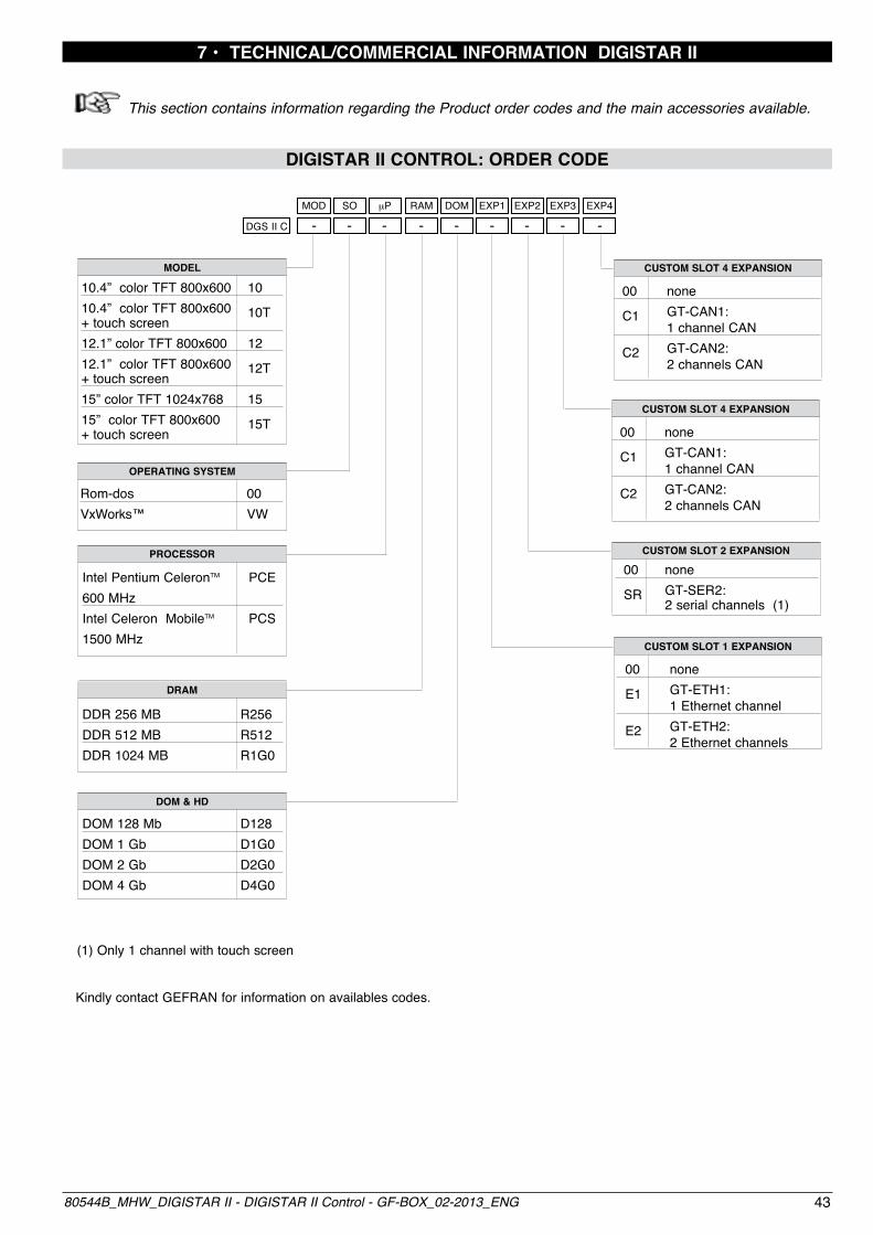
7 • TECHNICAL/COMMERCIAL INFORMATION DIGISTAR II
ThissectioncontainsinformationregardingtheProductordercodesandthemainaccessoriesavailable.
DIGISTAR II CONTROL: ORDER CODE
MODEL
10.4” color TFT 800x600 1010.4” color TFT 800x600 10T+ touch screen12.1” color TFT 800x600 1212.1” color TFT 800x600 12T+ touch screen15” color TFT 1024x768 1515” color TFT 800x600 15T+ touch screen
(1) Only 1 channel with touch screen
OPERATING SYSTEM
Rom-dos 00VxWorks™ VW
CUSTOM SLOT 2 EXPANSION
00 none SR GT-SER2: 2 serial channels (1)
CUSTOM SLOT 4 EXPANSION
00 none C1 GT-CAN1: 1 channel CAN C2 GT-CAN2: 2 channels CAN
MOD SO mP RAM DOM EXP1 EXP2 EXP3 EXP4
DGS II C - - - - - - - - -
CUSTOM SLOT 1 EXPANSION
00 none E1 GT-ETH1: 1 Ethernet channel E2 GT-ETH2: 2 Ethernet channels
CUSTOM SLOT 4 EXPANSION
00 none C1 GT-CAN1: 1 channel CAN C2 GT-CAN2: 2 channels CAN
Kindly contact GEFRAN for information on availables codes.
PROCESSOR
Intel Pentium CeleronTM PCE600 MHz Intel Celeron MobileTM PCS1500 MHz
DRAM
DDR 256 MB R256DDR 512 MB R512DDR 1024 MB R1G0
DOM & HD
DOM 128 Mb D128DOM 1 Gb D1G0DOM 2 Gb D2G0DOM 4 Gb D4G0

44 80544B_MHW_DIGISTAR II - DIGISTAR II Control - GF-BOX_02-2013_ENG
DIGISTAR II: ORDER CODE
MODEL
10.4” color TFT 800x600 1010.4” color TFT 800x600 10T+ touch screen12.1” color TFT 800x600 1212.1” color TFT 800x600 12T+ touch screen15” color TFT 1024x768 1515” color TFT 800x600 15T+ touch screen
(1) Requires HD20 option(2) Minimum hard disk capacity depends on market conditions(3) Only 1 channel with touch screen
OPERATING SYSTEM
Rom-dos 00Windows XP Pro MUI XP Pack™ (1)Windows XP embedded™ XE
DRAM
DDR 256 MB R256DDR 512 MB R512DDR 1024 MB R1G0
DOM & HD
DOM 1 Gb D1G0DOM 2 Gb D2G0DOM 4 Gb D4G0Hard Disk (2) HD20
CUSTOM SLOT 3 EXPANSION
00 none
CUSTOM SLOT 2 EXPANSION
00 none SR GT-SER 2 serial channels (3)
CUSTOM SLOT 4 EXPANSION
00 none
Kindly contact GEFRAN for information on availables codes.
MOD SO mP RAM DOM EXP1 EXP2 EXP3 EXP4
CUSTOM SLOT 1 EXPANSION 00 none E1 GT-ETH1: 1 Ethernet channel E2 GT-ETH2 : 2 Ethernet channels
PROCESSOR
Intel Pentium CeleronTM PCE600 MHz Intel Pentium Celeron PCSMobileTM 1500 MHz
DGS II - - - - - - - - -

4580544B_MHW_DIGISTAR II - DIGISTAR II Control - GF-BOX_02-2013_ENG
GF-BOX: ORDER CODE
DISTANCE OF DISPLAY
Local (max 3 m) LOC
(1) Requires options R256 and HD20(2) Requires options R256 and D1G0(3) Minimum hard disk capacity depends on availability(4) Not available with XP and XE option(5) Only for 1 channel with touch screen
OPERATING SYSTEM
Rom-dos 00VxWorks VWWindows XP Pro XPMUI Pack ™(1)Windows XP Embedded™ XE(2)
DRAMDDR 256 MB R256DDR 512 MB R512DDR 1 GB R1G0
DOM & HDDOM 128 Mb D128DOM 1 Gb D1G0DOM 2 Gb D2G0DOM 4 Gb D4G0Hard Disk (3) HD20
CUSTOM SLOT 2 EXPANSION
00 none SR GT-SER 2: 2 serial channels (5)
CUSTOM SLOT 4 EXPANSION
00 none C1 GT-CAN 1: 1 channel CAN (4) C2 GT-CAN 2: 2 channels CAN (4)
Kindly contact GEFRAN for information on availables codes.
CONN OS mP RAM DOM EXP1 EXP2 EXP3 EXP4
GFBOX - - - - - - - - -
CUSTOM SLOT 1 EXPANSION
00 none E1 GT-ETH 1: 1 Ethernet channel E2 GT-ETH 2: 2 Ethernet channels
CUSTOM SLOT 3 EXPANSION
00 none C1 GT-CAN 1: 1 channel CAN (4) C2 GT-CAN 2: 2 channels CAN (4)
000
PROCESSORIntel Pentium CeleronTM PCE600 MHz Intel Pentium Celeron PCSMobileTM 1500 MHz