Embed Size (px)
Citation preview

OPERATION MANUAL
DIGIFORCE® 9311 PROFINET Integration into TIA Portal
Manufacturer: © 2018 burster
praezisionsmesstechnik gmbh & co kg burster präzisionsmesstechnik gmbh & co kg
All rights reserved Talstr. 1 - 5 P.O. Box 1432 76593 Gernsbach 76587 Gernsbach Germany Germany Valid from: 01.08.2018 Tel.: +49-7224-645-0 Applies to: DIGIFORCE® 9311-VXX03 Fax.: +49-7224-645-88 Email: [email protected] www.burster.com 2768-BA9311PROFINTIAEN-5770-071525
2 of 21
Table of Contents Introduction ............................................................................................................................................................ 3
1. Creating new project ............................................................................................................................... 4 2. Installation of GSDML files ...................................................................................................................... 6 3. Creation of network connections ............................................................................................................. 7 4. Create a sample program ..................................................................................................................... 10 5. Further Examples .................................................................................................................................. 15
5.1 Reading and Writing of string data types .............................................................................................. 16 5.2 Retrieving of measurement results ....................................................................................................... 18 5.3 Changing of window limits ..................................................................................................................... 20

3 of 21
Introduction This quick start guide describes an approach how you can configure the DIGIFORCE® 9311 via TIA Portal using the example of S7-1511 CPU. Please note that the samples here cannot be directly used in your production line because they have beed extremely simplified to reach a better understanding. Therefore, you may have to complete them by checking of status, error, length values etc.
Please also note that you will have to use the DIGIFORCE 9311 PROFINET manual to get futher information about input and output parameters (cyclic as well acyclic data transfer)

4 of 21
1. Creating new project Start the Totally Integrated Automation Protal, select Create New Project (a), assign the project
a name (b) and click Create (c):
a b
c

5 of 21
Go to Devices & networks (a) on the left side select Add new device (b) and look for yor CPU (c). Afterwards click the Add button (d).
b
c
d
a

6 of 21
2. Installation of GSDML files Note: Please make sure that your GSDML file is compatible to the field bus firmware in the DIGIFORCE®
9311. Also for compatibility reasons, uninstall all previous GSDML files of particular device if you have any!
Go to Options->Manage general station description files (GSD)
Navigate to your DIGIFORCE® 9311 GSDML directory (a)(you will find the GSD files on burster DVD
that you got with your DIGIFORCE® 9311 device or on burster.com), select the GSD file (b) and click Install (c)
a
b
c
a

7 of 21
3. Creation of network connections Double click Device Configuration (a) in the project tree und switch to Network view (b) :
Now select the DIGIFORCE® 9311 device in the catalog and drag & drop it into the working area (a):
a
b
a

8 of 21
Please select an ethernet port on the S7 and hold the left mouse button down to connect the S7 with DIGIFORCE® 9311:
a

9 of 21
Change now to Network view (a) to assign a controller to the DIGIFORCE® 9311. Click on the link “Not assigned” (b) of DIGIFORCE® 9311 and select your controller (c):
Check if devices also connected physically to the right ports. You find the port number assignment in the section 4.3 Port-Identification of DIGIFORCE® 9311 PROFINET manual
a
c
b

10 of 21
4. Create a sample program In this section, you will learn how to create a simple program to start and stop a measurement periodically. You will need to refer to sections 7.2 PLC inputs and 7.3 PLC outputs of the DIGIFORCE® 9311 PROFINET manual to understand the meaning of inputs and outputs bytes.
Expand the tree node Program blocks in the Project tree and double click Add new block:

11 of 21
Select in the new window Organization block (a) and then Cyclic interrupt (b). As language set SCL (c), change the cyclic time to 1.000.000 µs (d) and click OK (e):
Type in the following source code in the code fild of the new block:
IF %Q258.0 = TRUE THEN %Q258.0 := FALSE; ELSE IF %I256.0 = FALSE THEN RETURN; END_IF; %Q258.0 := TRUE; END_IF;
// is IN_START (measurement start) set? // IN_START (measurement start) is set, then reset it // IN_START is not set // is OUT_READY (DIGIFORCE® 9311 ready for measurement) set? // If not - // return // set IN_START(measurement start)
a
b
c
d
e

12 of 21
Please note: the addresses may be different. You have to check them in the Device view->Device overview of the DIGIFORCE® 9311.
You will also see that the TIA-Editor replaces the input/output addresses with tags. You can change the tags names in PLC Tag table (e.g. to IN_START and OUT_READY):
13 of 21
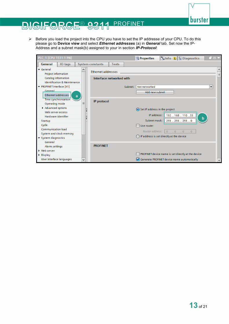
Before you load the project into the CPU you have to set the IP addresse of your CPU. To do this please go to Device view and select Ethernet addresses (a) in General tab. Set now the IP-Address and a subnet mask(b) assigned to your in section IP-Protocol:
a
b
14 of 21
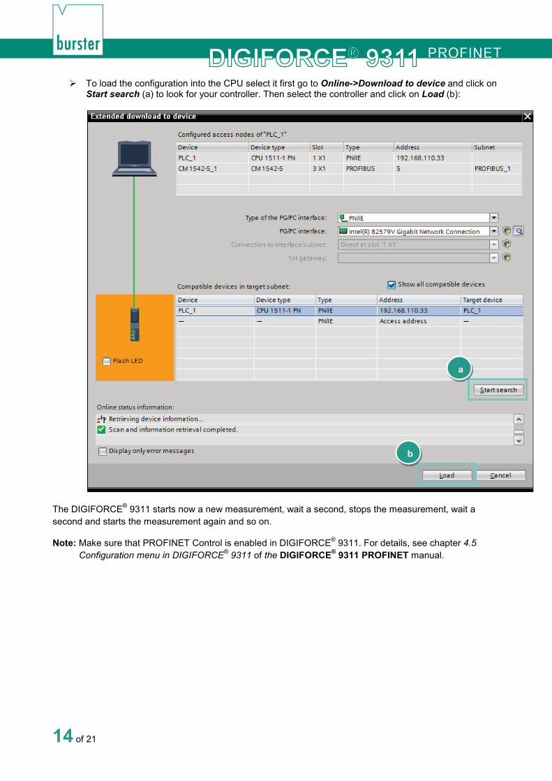
To load the configuration into the CPU select it first go to Online->Download to device and click on Start search (a) to look for your controller. Then select the controller and click on Load (b):
The DIGIFORCE® 9311 starts now a new measurement, wait a second, stops the measurement, wait a second and starts the measurement again and so on.
Note: Make sure that PROFINET Control is enabled in DIGIFORCE® 9311. For details, see chapter 4.5 Configuration menu in DIGIFORCE® 9311 of the DIGIFORCE® 9311 PROFINET manual.
a
b

15 of 21
5. Further Examples In the followed examples, a Hardware-ID is used to access a certain slot. To find this, please select a DIGIFORCE® 9311 device in Topology view or Network view and then switch to Device view. Click with the right mouse button on the desired module, e.g. General Setup and select Properties:
You will see the hardware indentifier in the tab General:

16 of 21
5.1 Reading and Writing of string data types
Example 1: Reading Device ID and write it as station name to device
In this example, we perform a read access on slot 30/Subslot 1/index 10 to get the device type of DIGIFORCE® 9311 and then we will set the first nine characters of this string as DIGIFORCE® 9311 station name on Slot 30/Subslot 1/Index 17. For these acyclic operations, you will need an instance of RDREC und WRREC blocks. You can see the new station name in the info menu of DIGIFORCE® 9311.
PLC parameters table:
Sourcecode:
REPEAT "RDREC_DB"(REQ:=TRUE, ID:=268, // 268: HW-ID for General Setup (see introduction of 'Further examples') INDEX:=10, // Index 10: Device Detection MLEN:=18, // Max. lenth of data to read VALID=>#Valid, // New Data Received and valid BUSY=>#Busy, // Read not completed yet ERROR=>#Error, // Error STATUS=>#Status, // State LEN=>#lenRead, // Number of bytes was read from device RECORD:= #data); // Array[0..18] of Byte UNTIL NOT #Busy END_REPEAT; IF #Error = TRUE OR #Status <> 0 THEN RETURN; END_IF; REPEAT "WRREC_DB"(REQ:=TRUE, ID:=268, // 268: HW-ID for General Setup (see introduction of 'Further examples') INDEX:=17, // Index 17: Station Name LEN:=9, // Length of data to write DONE=>#Done, // Write done BUSY=>#Busy, // Write not completed yet ERROR=>#Error, // Error STATUS=>#Status, // State RECORD:=#data); // Write the data has being read in RDREC_DB (first 9 bytes) UNTIL NOT #Busy AND #Done END_REPEAT;

17 of 21
Example 2: Writing of serial number SN1 into device order sheet
Note: Datatype String in TIA Portal contains two additional bytes, which represent the length of the string. To avoid these two bytes being sent use the function ‘Strg_TO_Chars’ to convert the String to a byte array as shown below:
PLC parameters table:
Sourcecode:
#serial := 'SN123456789'; Strg_TO_Chars(Strg:= #serial, // Serial as String pChars:= 0, // Position in serialAsByteArray Cnt => #bytesWritten, // Number of Bytes have been written to serialAsByteArray Chars:= #serialAsByteArray); REPEAT "WRREC_DB"(REQ := TRUE, ID := 268, // HW-ID General Setup (see introduction of 'Further examples') INDEX := 65, // Index 65: Order sheet - Serial number 1 LEN := INT_TO_UINT(LEN(#serial)), // Length of serial DONE => #Done, // Write done BUSY => #Busy, // Write not completed yet ERROR => #Error, // Error STATUS => #Status, // State RECORD := #serialAsByteArray); UNTIL NOT #Busy AND #Done END_REPEAT;
18 of 21
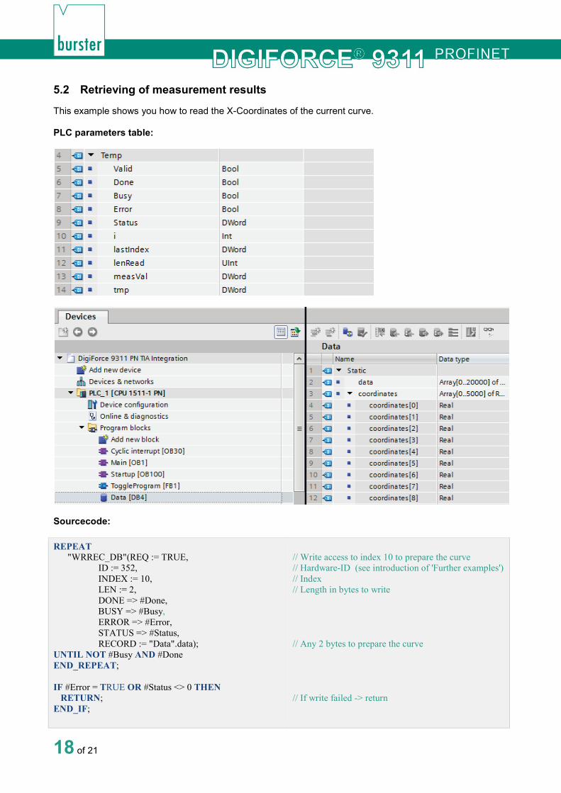
5.2 Retrieving of measurement results
This example shows you how to read the X-Coordinates of the current curve.
PLC parameters table:
Sourcecode:
REPEAT "WRREC_DB"(REQ := TRUE, ID := 352, INDEX := 10, LEN := 2, DONE => #Done, BUSY => #Busy, ERROR => #Error, STATUS => #Status, RECORD := "Data".data); UNTIL NOT #Busy AND #Done END_REPEAT; IF #Error = TRUE OR #Status <> 0 THEN RETURN; END_IF;
// Write access to index 10 to prepare the curve // Hardware-ID (see introduction of 'Further examples') // Index // Length in bytes to write // Any 2 bytes to prepare the curve // If write failed -> return

19 of 21
REPEAT "RDREC_DB"(REQ := TRUE, ID := 352, INDEX := 10, MLEN := 4, VALID => #Valid, BUSY => #Busy, ERROR => #Error, STATUS => #Status, LEN => #lenRead, RECORD := #lastIndex); UNTIL NOT #Busy END_REPEAT; #lastIndex := SHR(IN := #lastIndex, N := 16); IF #Error = TRUE OR #Status <> 0 OR #lenRead <> 2 OR #lastIndex = 0 THEN RETURN; END_IF; REPEAT "RDREC_DB"(REQ := TRUE, ID := 352, INDEX := 11, MLEN := 20000, VALID => #Valid, BUSY => #Busy, ERROR => #Error, STATUS => #Status, LEN => #lenRead, RECORD := "Data".data); UNTIL NOT #Busy END_REPEAT; IF #Error = TRUE OR #Status <> 0 OR #lenRead < 4 THEN RETURN; END_IF; FOR #i := 0 TO DWORD_TO_INT(#lenRead - 1) BY 4 DO #measVal := 0; #tmp := BYTE_TO_DWORD("Data".data[#i]); #measVal := #measVal + SHL(IN := #tmp, N := 24); #tmp := BYTE_TO_DWORD("Data".data[#i + 1]); #measVal := #measVal + SHL(IN := #tmp, N := 16); #tmp := "Data".data[#i + 2]; #measVal := #measVal + SHL(IN := #tmp, N := 8); #measVal := #measVal + "Data".data[#i + 3]; "Data".coordinates[#i / 4] := DWORD_TO_REAL(#measVal); END_FOR;
// Read the number of curve values // Hardware-ID (see introduction of 'Further examples') // Index // Max. length to read // Number of bytes read // Number of values in the curve - 1 // upto and including DIGIFORCE® 9311 field bus firmware FW-2018.1.0 we have to use DWord to get U16 Types from DIGIFORCE® 9311 and shift left the result by 2 bytes // If read failed -> return // Read access to read out curve coordinates // Hardware-ID (see introduction of 'Further examples') // Index // Max. length to read // Number of bytes read // Array to store the read coordinates // If read failed -> return // Write bytes to DWORD and convert to Real // Shift left the value by 24 bit // Shift left the value by 16 bit // Shift left the value by 8 bit // Convert to Real and store in MeasValues[] Array

20 of 21
5.3 Changing of window limits
This example shows you how to enable Evaluation Window 1 and set its coordinates.
Note: You have to write all four window limits and then confirm them with index 15. It is not possible to change only one single limit, e.g. xMax.
PLC parameters tables:
Sourcecode:
#onOff := 1; // Activate Window 1 #event := 1; // Acknowledgement for indices 11, 12, 13,14 #xMin := 1.5; // Xmin coorrdinate of window 1 #xMax := 3.0; // Xmax coorrdinate of window 1 #yMin := 2.5; // Ymin coorrdinate of window 1 #yMax := 4.0; // Ymax coorrdinate of window 1 REPEAT "WRREC_DB"(REQ := TRUE, ID := 286, // HW-ID for Evaluation Window 1 (see introduction of 'Further examples') INDEX := 10, // Index 10: switch on window 1 LEN := 2, // Length of UINT16 DONE => #Done, // Write done BUSY => #Busy, // Write not completed yet ERROR => #Error, // Error STATUS => #Status, // State RECORD := #onOff); UNTIL NOT #Busy AND #Done END_REPEAT; REPEAT "WRREC_DB"(REQ := TRUE, ID := 286, // 286: HW-ID for Evaluation Window 1 (see introduction of 'Further examples') INDEX := 11, // Index 11: Window 1 limit Xmin LEN := 4, // Length of UINT16 DONE => #Done, // Write done BUSY => #Busy, // Write not completed yet

21 of 21
ERROR => #Error, // Error STATUS => #Status, // State RECORD := #xMin); UNTIL NOT #Busy AND #Done END_REPEAT; REPEAT "WRREC_DB"(REQ := TRUE, ID := 286, // HW-ID for Evaluation Window 1 (see introduction of 'Further examples') INDEX := 12, // Index 12: Window 1 limit Xmax LEN := 4, // Length of Real DONE => #Done, // Write done BUSY => #Busy, // Write not completed yet ERROR => #Error, // Error STATUS => #Status, // State RECORD := #xMax); UNTIL NOT #Busy AND #Done END_REPEAT; REPEAT "WRREC_DB"(REQ := TRUE, ID := 286, // HW-ID for Evaluation Window 1 (see introduction of 'Further examples') INDEX := 13, // Index 13: Window 1 limit Ymin LEN := 4, // Length of Real DONE => #Done, // Write done BUSY => #Busy, // Write not completed yet ERROR => #Error, // Error STATUS => #Status, // State RECORD := #yMin) ; UNTIL NOT #Busy AND #Done END_REPEAT; REPEAT "WRREC_DB"(REQ := TRUE, ID := 286, // HW-ID for Evaluation Window 1 (see introduction of 'Further examples') INDEX := 14, // Index 14: Window 1 limit Ymax LEN := 4, // Length of Real DONE => #Done, // Write done BUSY => #Busy, // Write not completed yet ERROR => #Error, // Error STATUS => #Status, // State RECORD := #yMax); UNTIL NOT #Busy AND #Done END_REPEAT; REPEAT "WRREC_DB"(REQ := TRUE, ID := 286, // HW-ID for Evaluation Window 1 (see introduction of 'Further examples') INDEX := 15, // Index 15: adopt values entered into indices 11, 12, 13,14 LEN := 1, // Length of Real DONE => #Done, // Write done BUSY => #Busy, // Write not completed yet ERROR => #Error, // Error STATUS => #Status, // State RECORD := #event); UNTIL NOT #Busy AND #Done END_REPEAT;