Embed Size (px)
Citation preview

Mounting and Operating Instructions
EB 9519 EN
Tran
slatio
n of
orig
inal
instr
uctio
ns
Edition August 2016
Media 5 with 4 to 20 mA current output Media 5 with limit switch
Mounted valve block and pressure gauge for operating pressure
Differential Pressure and Flow MeterMedia 5
2 EB9519EN
Noteonthesemountingandoperatinginstructions
These mounting and operating instructions assist you in mounting and operating the device safely. The instructions are binding for handling SAMSON devices.
Î For the safe and proper use of these instructions, read them carefully and keep them for later reference.
Î If you have any questions about these instructions, contact SAMSON‘s After-sales Service Department ([email protected]).
The mounting and operating instructions for the devices are included in the scope of delivery. The latest documentation is available on our website (www.samson.de) > Product documentation. You can enter the document number or type number in the [Find:] field to look for a document.
Definition of signal words
Hazardous situations which, if not avoided, will result in death or serious injury
Hazardous situations which, if not avoided, could result in death or serious injury
Property damage message or malfunction
Additional information
Recommended action
DANGER!
WARNING!
NOTICE!
Note
Tip

Contents
EB9519EN 3
1 Safetyinstructions .........................................................................................52 Designandprincipleofoperation ..................................................................62.1 Optional modules ..........................................................................................63 Technicaldata ...............................................................................................84 Installation ..................................................................................................104.1 Arrangement of instruments for liquid level measurement ................................104.2 Arrangement of devices for flow rate measurement .........................................104.3 Media 5 indicating unit ................................................................................104.4 Differential pressure lines ..............................................................................104.5 Orifice flange (orifice plate assembly) ............................................................124.5.1 Accessories .................................................................................................124.5.2 Valve block ..................................................................................................124.5.3 Shut-off and equalizing valves ......................................................................134.5.4 Compensation chambers ..............................................................................134.5.5 Accessories for connection ............................................................................135 Start-up ......................................................................................................145.1 Liquid level measurement ..............................................................................145.2 Flow rate measurement .................................................................................146 Operation ...................................................................................................156.1 Zero calibration ...........................................................................................156.2 Checking zero .............................................................................................156.3 Water drainage ...........................................................................................166.4 Adjusting and modifying the measuring range ...............................................167 Limitswitch(optional) ..................................................................................187.1 Electrical connection .....................................................................................187.2 Adjusting the alarm contacts .........................................................................197.3 Retrofitting/replacing the contact unit ............................................................208 4to20 mAcurrentoutput(optional) ............................................................238.1 Retrofitting ...................................................................................................238.2 Settings .......................................................................................................268.3 Nameplate ..................................................................................................29

4 EB9519EN
Contents
9 Dialfaces ....................................................................................................309.1 Attachable dial plates ...................................................................................3010 Dimensions .................................................................................................32
Devices intended to measure gaseous oxygen are labeled Oxygen! Keepfreeofoilandgrease!These versions are cleaned and assembled under special conditions. When replacing parts that come into contact with gaseous oxygen, e.g. range springs, wear suitable gloves and make sure that the parts do not come into contact with oil or grease.When returning devices for oxygen service for repair, the sender assumes full responsibility that the devices are handled to meet all requirements stipulated by VBG 62 or similar regulations until they are handed over to the manufacturer. Otherwise, SAMSON AG does not accept any responsibility.
NOTICE!

EB9519EN 5
Safetyinstructions
1 Safetyinstructions − The device is to be mounted, started up or operated only by trained and experienced
personnel familiar with the product. According to these mounting and operating instructions, trained personnel refers to individuals who are able to judge the work they are assigned to and recognize possible dangers due to their specialized training, their knowledge and experience as well as their knowledge of the applicable standards.
− Any hazards that could be caused in the device by the process medium or operating pressure are to be prevented by taking appropriate precautions. To ensure appropriate use, only use the device in applications where the operating pressure and temperatures do not exceed the specifications used at the ordering stage.
− The Media 5 Differential Pressure and Flow Meter without limit switches may be used to measure flammable gases and liquids in which hazardous area conditions of Zone 0 are to be expected. This means that measuring instrument suited for the connection to Zone 0 can be installed provided:1. The pipes connecting the instruments have been sized and installed according to the
German Technical Regulations for Flammable Liquids TRbF 50 or2. Flame arresters or endurance burning flame arresters have been installed in the two
measuring lines.Whether you have to install flame arresters or endurance burning flame arresters depends on the conditions on site. However, endurance burning flame arresters are preferably to be installed. You are required to contact the appropriate regulatory authority to agree on the necessary measures.The operator is responsible for meeting the above specified requirements specified (1 and 2). SAMSON AG does not assume any responsibility if the operator fails to do so.
− Proper shipping and storage are assumed. − Devices with a CE marking fulfill the requirements of the Directive 2014/34/EU (ATEX)
and the Directive 89/336/EEC. This EC declaration of conformity can be provided on re-quest.
6 EB9519EN
Designandprincipleofoperation
2 Designandprincipleofoper-ation
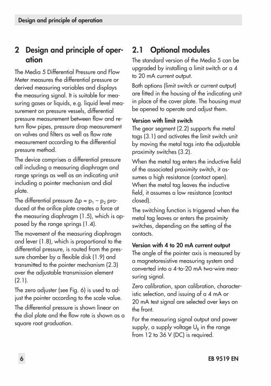
The Media 5 Differential Pressure and Flow Meter measures the differential pressure or derived measuring variables and displays the measuring signal. It is suitable for mea-suring gases or liquids, e.g. liquid level mea-surement on pressure vessels, differential pressure measurement between flow and re-turn flow pipes, pressure drop measurement on valves and filters as well as flow rate measurement according to the differential pressure method.The device comprises a differential pressure cell including a measuring diaphragm and range springs as well as an indicating unit including a pointer mechanism and dial plate.The differential pressure ∆p = p1 – p2 pro-duced at the orifice plate creates a force at the measuring diaphragm (1.5), which is op-posed by the range springs (1.4).The movement of the measuring diaphragm and lever (1.8), which is proportional to the differential pressure, is routed from the pres-sure chamber by a flexible disk (1.9) and transmitted to the pointer mechanism (2.3) over the adjustable transmission element (2.1).The zero adjuster (see Fig. 6) is used to ad-just the pointer according to the scale value.The differential pressure is shown linear on the dial plate and the flow rate is shown as a square root graduation.
2.1 OptionalmodulesThe standard version of the Media 5 can be upgraded by installing a limit switch or a 4 to 20 mA current output.Both options (limit switch or current output) are fitted in the housing of the indicating unit in place of the cover plate. The housing must be opened to operate and adjust them.
VersionwithlimitswitchThe gear segment (2.2) supports the metal tags (3.1) and activates the limit switch unit by moving the metal tags into the adjustable proximity switches (3.2).When the metal tag enters the inductive field of the associated proximity switch, it as-sumes a high resistance (contact open). When the metal tag leaves the inductive field, it assumes a low resistance (contact closed).The switching function is triggered when the metal tag leaves or enters the proximity switches, depending on the setting of the contacts.
Versionwith4to20 mAcurrentoutputThe angle of the pointer axis is measured by a magnetoresistive measuring system and converted into a 4-to-20 mA two-wire mea-suring signal.Zero calibration, span calibration, character-istic selection, and issuing of a 4 mA or 20 mA test signal are selected over keys on the front.For the measuring signal output and power supply, a supply voltage UB in the range from 12 to 36 V (DC) is required.

EB9519EN 7
Designandprincipleofoperation
Housingofindicatingunit
Differentialpressurecell
Limitswitch(option)
2.4
2.3
2.2
2.13.13.2
A1 A2
1.1
1.3
1.4
1.9
1.8
1.2
1.71.61.5
_ +
Differentialpressurecell1.1 dp-cell1.2 High-pressure chamber1.3 Low-pressure chamber1.4 Range springs1.5 Measuring diaphragm1.6 Diaphragm plates1.7 Diaphragm stem1.8 Lever1.9 Flexible diskHousingofindicatingunit2.1 Transmission element
(span adjuster)2.2 Gear segment2.3 Pointer mechanism2.4 Dial plate
Limitswitch (option)3.1 Metal tag3.2 Proximity switches A1/A2
Currentoutput(option)4.1 Status indication (green)4.2 Error indication (red)4.3 Execute/confirm key4.4 Select function/data key
4.4 4.3
4.14.2
Fig. 1: Functional diagram of Media 5 with limit switch

8 EB9519EN
Technicaldata
3 TechnicaldataTable 1: Technical data · All pressure in bar (gauge) · All errors and deviations are specified in % of the adjusted measuring spanMedia 5DifferentialPressureandFlowMeterMeasuring range in mbar
0 to 60
0 to 100
0 to 160
0 to 250
0 to 400
0 to 600
0 to 1000
0 to 1600
0 to 2500
0 to 3600
Measuring span in mbar
min. max.
40 to 60
50 to 100
80 to 160
125 to 250
200 to 400
300 to 600
500 to 1000
800 to 1600
1250 to 2500
1800 to 3600
Nominal pressure PN 50, overloadable on one side up to 50 barIndicator Ø 160 mmCharacteristic Reading linear to the differential pressureDeviation from terminal-based linearity <±2.5 % <±1.6 % including hysteresis
Sensitivity <±0.5 % <±0.25 %Effect of static pressure <0.03 %/1 barDegree of protection according to IEC 60529 IP 54
Weight Approx. 3 kg without valve block · Approx. 5 kg with valve blockComplianceLimitswitch(optional)
Version Max. 3 alarm contacts A1, A2 and A3 (limit switches) with inductive pick-up and LED according to EN 60947-5-6
Control circuit Values corresponding to connected isolating switch amplifier according to EN 60947-5-6, e.g. KFA6-SR2-Ex2.W
Proximity switch SJ3,5-N-LED, for hazardous areas according to PTB 99 ATEX 2219XSwitching accuracy <±2 %Dead band, approx. <0.6 %Currentoutput(optional)Version Magnetoresistive measuring systemSupply voltage UB 12 to 36 V (DC)Output signal 4 to 20 mA, two-wire systemPerm. load RB in Ω RB = (UB – 12 V)/0.020 A (R ≤600 Ω at 24 V and 20 mA)Power consumption 103 mWSettings Zero calibration|Span calibration|Characteristic selection|Test function
CharacteristicOutput and reading linear or square root extraction depending on installed flow
characteristic Characteristic set at the factory
Deviation from terminal-based linearity <±0.2 %, related to 270° measuring span
Sensitivity <±0.05 %, related to 270° measuring spanEffect of ambient temp.from –40 to +80 °C <0.1 %/10 K for zero and span
EB9519EN 9
Technicaldata
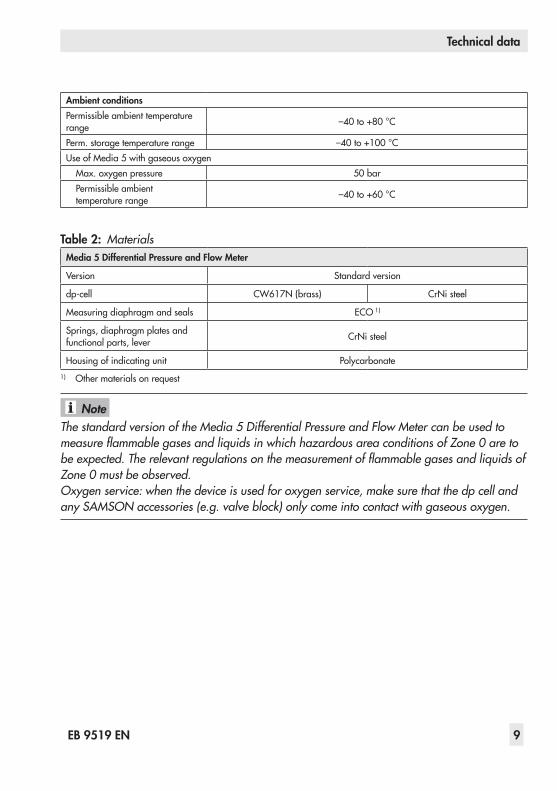
AmbientconditionsPermissible ambient temperature range –40 to +80 °C
Perm. storage temperature range –40 to +100 °CUse of Media 5 with gaseous oxygen
Max. oxygen pressure 50 barPermissible ambient temperature range –40 to +60 °C
Table 2:MaterialsMedia 5DifferentialPressureandFlowMeter
Version Standard version
dp-cell CW617N (brass) CrNi steel
Measuring diaphragm and seals ECO 1)
Springs, diaphragm plates and functional parts, lever CrNi steel
Housing of indicating unit Polycarbonate1) Other materials on request
The standard version of the Media 5 Differential Pressure and Flow Meter can be used to measure flammable gases and liquids in which hazardous area conditions of Zone 0 are to be expected. The relevant regulations on the measurement of flammable gases and liquids of Zone 0 must be observed.Oxygen service: when the device is used for oxygen service, make sure that the dp cell and any SAMSON accessories (e.g. valve block) only come into contact with gaseous oxygen.
Note

10 EB9519EN
Installation
4 InstallationSee Fig. 2 on page 11.
4.1 Arrangementofinstrumentsforliquidlevelmeasurement
In arrangements as illustrated in the second schematic drawing, the additional height z is included in the measurement. As a result, this height must be as low as possible.The dimension K (compensation height, Dia-gram 3) can be as large as required by the conditions in the plant.
4.2 Arrangementofdevicesforflowratemeasurement
The decision whether the meter is to be mounted above or below the measuring point or whether compensation chambers are required depends on the process medi-um and the specific conditions in the plant. The installation drawing shows standard and reverse installation. Standard installation is preferable in any case. Reverse installation can only be used when there is no other pos-sibility, particularly for steam measurements. Refer to VDE/VDI 3512 Sheet 1 for details.
4.3 Media 5indicatingunitMake sure that the high-pressure line is con-nected to the high-pressure connection and the low-pressure line to the low-pressure con-nection.
Special screw fittings are required to connect the differential pressure lines. Depending on the device arrangement, seal any connec-tions left unused with stoppers or vent plugs.Carefully clean the connections before at-taching the differential pressure lines. Do not rinse the device with compressed air or pres-surized water.Mount the device to a pipe, wall or mounting plate free of vibration.Use mounting part with clamp for pipe mounting to attach it to a vertical or horizon-tal pipe. Use a mounting part without clamp for wall mounting. A mounting bracket is re-quired for panel mounting (see section 10).
4.4 DifferentialpressurelinesInstall the differential pressure lines (pipes with 12 mm outside diameter) as shown in Fig. 3. Observe the proper sequence. Use appropriate screw fittings to ensure that the lines do not leak.Install line sections, which would usually run horizontally, with a constant downward slope of at least 1:20, starting the slope ei-ther at the orifice plate or at the point where venting is possible. The smallest permissible bending radius is 50 mm. Thoroughly flush the differential pressure lines before connect-ing them to the device. Make sure that the high-pressure line is connected to the high-pressure connection and the low-pres-sure line to the low-pressure connection.

EB9519EN 11
Installation
LiquidlevelmeasurementIllustration with SAMSON valve block
hH
zh
H h
K
H
Y
+– +–+–
H Measuring rangeh Measured heightz Additional heightK Compensation height
Diagram 1Measurements in cryogenic systems
(liquefied gases)
Diagram 2Measurement on pressure vessels
with condensing or non-condensing pressure cushion
Diagram 3Measurements on open vessels with the meter located in a low position
FlowratemeasurementMeasurement of liquids Measurement of steam Measurement of gases
1) 1) 1)
Orifice flange (orifice plate assembly) Compensation chamber
Separation chamber
InstallationStandard Reverse Standard Standard Reverse
1) SAMSON valve blocks can be mounted upside down to ensure the assignment of plus (+) to plus (+) and minus (–) to minus (–) remains unchanged.
Fig. 2: Arrangement of devices

12 EB9519EN
Installation
4.5 Orificeflange(orificeplateassembly)
The direction of flow must correspond to the arrow on the orifice plate. Unobstructed pipe sections are required upstream and down-stream of the orifice plate assembly. For the orifice tubes delivered by SAMSON, these section are ensured by the weld-on calibra-tion pipes. For orifice flanges, the unobstruct-ed pipe section upstream of the orifice plate is specified in the order confirmation. Make sure the orifice plate assembly as well as the gaskets are properly aligned with the pipe-line.Do not install any control valves that con-stantly change the operating state of the pro-cess medium (e.g. manually operated control valves or temperature regulators) upstream of the orifice plate assembly. The operating state must match the conditions calculated during sizing as closely as possible. It is, however, favorable to install equipment that
keep the operating state constant (e.g. pres-sure regulators) upstream of the assembly.
4.5.1 AccessoriesWe recommend installing a shut-off valve in the differential pressure lines as well as an equalizing valve. They can be used to shut off both differential pressure lines and to by-pass the indicating unit when checking zero.
4.5.2 ValveblockA valve block comprising three valves (see Fig. 4) is available. It is bolted directly to the bottom of the dp cell.When measuring the flow rate of liquids and gases, the SAMSON valve block can also be mounted upside down. As a result, the as-signment of plus (+) to plus (+) and minus (–) to minus (–) remains unchanged. Due to this reverse installation, the pressure gauge con-nection cannot be used anymore and must be sealed with an O-ring and a G ½ - LH screw cap.
Type 90 Orifice Flange
Inlet 20 to 50 x dOutlet 5 x d
For gas For steam For liquids
The maximum permissible operating pressure for Type 90 is 40 bar in the standard version.
NOTICE!
Location of the differential pressure lines on the orifice plate assembly
Fig. 3: Orifice flange (orifice plate assembly)

EB9519EN 13
Installation
4.5.3 Shut-offandequalizingvalves
As an alternative to the SAMSON valve block, the two shut-off valves as well as the bypass valve/equalizing valve can also be installed as illustrated in Fig. 5.
4.5.4 CompensationchambersCompensation chambers that establish a constant liquid column are required when measuring steam. When measuring liquids, they are only required when the indicating unit is mounted above the measuring point. For gas measurements, separation chambers are required for condensate separation when the indicating unit is installed below the measuring point.
4.5.5 Accessoriesforconnec-tion
The devices are delivered without screw fit-tings (oxygen versions are protected against contamination by four NBR blanking plugs). Required screw fittings, screw plugs or vent screws as well as screw joints with restric-tions to dampen medium-induced vibration (particularly when measuring gases) must be ordered separately.
The screw fittings and SAMSON valve blocks with their associated order numbers are list-ed in Data Sheet u T 9555.
Tip
Liquidlevelmeasurement Flowratemeasurement
– +
Pressure gauge connectionConnection for measuring lines
Hole for leading screw
Equalizing valveTest connection
Shut-off valve (–)Shut-off valve (+)
To the indicating unit
Fig. 4: SAMSON valve block
Fig. 5: Arrangement of shut-off valves and equalizing valves for flow rate measurement
1
2
To the indicating unit
From the measuring point
1 Shut-off valves2 Equalizing valve

14 EB9519EN
Start-up
5 Start-upSee Fig. 2, Fig. 3, Fig. 4 and Fig. 5.Based on the following valve positions on the valve block upon delivery: − Open high-pressure shut-off valve (+)
and low-pressure shut-off valve (–) − Closed equalizing valve
In cryogenic applications, the process me-dium circulates during measurement when the equalizing valve is opened, causing the valve block to ice up.During measurement, therefore, the equaliz-ing valve must be closed and the shut-off valves open.
If necessary, check zero at the dp cell and put the device back into operation.
5.1 Liquidlevelmeasurement1. Slowly open the low-pressure line.2. Close the equalizing valve or bypass of
the valve block.3. Slowly open the high-pressure line.
5.2 FlowratemeasurementForsteammeasurementMake sure that the steam does not have di-rect contact with the measuring diaphragm of the device. To prevent this, screw off the differential pressure lines below the shut-off valves or valve block and fill the device with water.
Alternatively, make sure the shut-off and equalizing valves or valve block are shut off and wait approx. 20 min after start up of the plant (steam in the system) until condensate has collected in the differential pressure lines above the valve and up to the orifice plate.1. Open the high-pressure line.2. Close the equalizing valve or bypass of
the valve block.3. Open the low-pressure line.4. Wait a while. Open both vent screws of
the dp cell one after the other until the escaping condensate is free of bubbles. Retighten the screws.Vent the compensation chambers in the same way.Lightly tap the housing of the indicating unit or the compensation chambers to help let the air escape.
5. Check zero as described in section 6.2 and put the device back into operation.
When using reverse installation (with the de-vice mounted above the measuring point), the differential pressure lines may partly get drained when depressurizing the system.
When starting up the system again, vent the measurement setup to allow it to fill with con-densate.
Forliquidmeasurement1. Slowly open the high-pressure line (turn
slowly).
NOTICE!
Note
EB9519EN 15
Operation
2. Close the equalizing valve or bypass of the valve block.
3. Open the low-pressure line.4. Undo the vent screw on the dp cell until
all the air has escaped. Retighten the screw.
5. Check zero (see section 6.2). Put the de-vice back into operation.
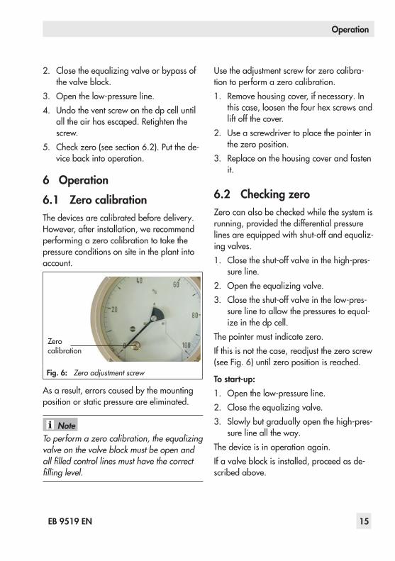
6 Operation6.1 ZerocalibrationThe devices are calibrated before delivery. However, after installation, we recommend performing a zero calibration to take the pressure conditions on site in the plant into account.
Zero calibration
Fig. 6: Zero adjustment screw
As a result, errors caused by the mounting position or static pressure are eliminated.
To perform a zero calibration, the equalizing valve on the valve block must be open and all filled control lines must have the correct filling level.
Use the adjustment screw for zero calibra-tion to perform a zero calibration.1. Remove housing cover, if necessary. In
this case, loosen the four hex screws and lift off the cover.
2. Use a screwdriver to place the pointer in the zero position.
3. Replace on the housing cover and fasten it.
6.2 CheckingzeroZero can also be checked while the system is running, provided the differential pressure lines are equipped with shut-off and equaliz-ing valves.1. Close the shut-off valve in the high-pres-
sure line.2. Open the equalizing valve.3. Close the shut-off valve in the low-pres-
sure line to allow the pressures to equal-ize in the dp cell.
The pointer must indicate zero.If this is not the case, readjust the zero screw (see Fig. 6) until zero position is reached.
Tostart-up:1. Open the low-pressure line.2. Close the equalizing valve.3. Slowly but gradually open the high-pres-
sure line all the way.The device is in operation again.If a valve block is installed, proceed as de-scribed above.
Note
16 EB9519EN
Operation
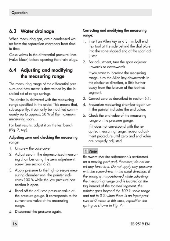
6.3 WaterdrainageWhen measuring gas, drain condensed wa-ter from the separation chambers from time to time.Close valves in the differential pressure lines (valve block) before opening the drain plugs.
6.4 Adjustingandmodifyingthemeasuringrange
The measuring range of the differential pres-sure and flow meter is determined by the in-stalled set of range springs.The device is delivered with the measuring range specified in the order. This means that, subsequently, it can only be modified contin-uously up to approx. 50 % of the maximum measuring span.For best results, adjust it on the test bench (Fig. 7, top).
Adjustingzeroandcheckingthemeasuringrange:1. Unscrew the case cover.2. Adjust zero in the depressurized measur-
ing chamber using the zero adjustment screw (see section 6.2).
3. Apply pressure to the high-pressure mea-suring chamber until the pointer indi-cates 100 % while the low pressure con-nection is open.
4. Read off the adjusted pressure value at the pressure gauge. It corresponds to the current end value of the measuring range.
5. Disconnect the pressure again.
Correctingandmodifyingthemeasuringrange:1. Insert an Allen key or a 3 mm ball end
hex tool at the side behind the dial plate into the cone-shaped end of the span ad-juster.
2. For adjustment, turn the span adjuster upwards or downwards.If you want to increase the measuring range, turn the Allen key downwards in the clockwise direction, a little further away from the fulcrum of the toothed segment.
3. Correct zero as described in section 6.1.4. Pressurize measuring chamber again un-
til the pointer indicates the end value.5. Check the end value of the measuring
range on the pressure gauge.If it does not correspond with the re-quired measuring range, repeat adjust-ment procedure until zero and end value are properly adjusted.
Be aware that the adjustment is performed on a moving part and, therefore, do not ex-ert any force to it. Do not apply any pressure with the screwdriver in the axial direction. If the spring is mispositioned while adjusting the measuring range and is located on the tag instead of the toothed segment, the pointer goes beyond the 100 % scale range and not to 0 % when there is an input pres-sure of 0 mbar. In this case, reposition the spring as shown in Fig. 7.
Note
EB9519EN 17
Operation
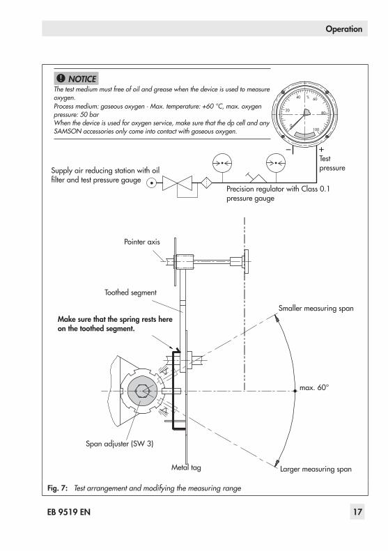
Supply air reducing station with oil filter and test pressure gauge
Precision regulator with Class 0.1 pressure gauge
Test pressure
Pointer axis
Toothed segment
Makesurethatthespringrestshereonthetoothedsegment.
Smaller measuring span
max. 60°
Larger measuring spanMetal tag
Span adjuster (SW 3)
– +
The test medium must free of oil and grease when the device is used to measure oxygen.Process medium: gaseous oxygen · Max. temperature: +60 °C, max. oxygen pressure: 50 barWhen the device is used for oxygen service, make sure that the dp cell and any SAMSON accessories only come into contact with gaseous oxygen.
NOTICE!
Fig. 7: Test arrangement and modifying the measuring range
18 EB9519EN
Limitswitch(optional)
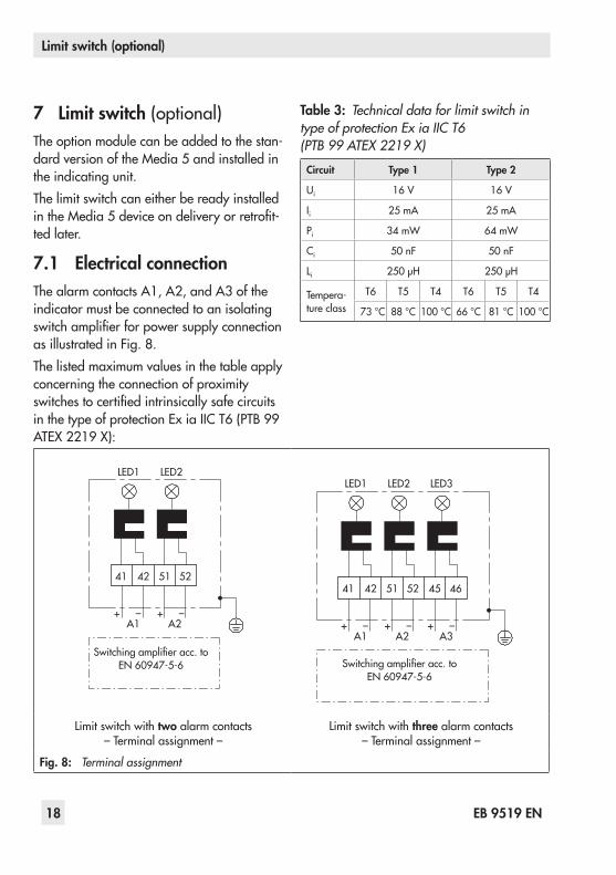
7 Limitswitch(optional)The option module can be added to the stan-dard version of the Media 5 and installed in the indicating unit.The limit switch can either be ready installed in the Media 5 device on delivery or retrofit-ted later.
7.1 ElectricalconnectionThe alarm contacts A1, A2, and A3 of the indicator must be connected to an isolating switch amplifier for power supply connection as illustrated in Fig. 8.The listed maximum values in the table apply concerning the connection of proximity switches to certified intrinsically safe circuits in the type of protection Ex ia IIC T6 (PTB 99 ATEX 2219 X):
Table 3: Technical data for limit switch in type of protection Ex ia IIC T6 (PTB 99 ATEX 2219 X)
Circuit Type 1 Type 2
Ui 16 V 16 V
Ii 25 mA 25 mA
Pi 34 mW 64 mW
Ci 50 nF 50 nF
Li 250 μH 250 μH
Tempera-ture class
T6 T5 T4 T6 T5 T4
73 °C 88 °C 100 °C 66 °C 81 °C 100 °C
41
LED1
A1+ – + –
A2
LED2
42 51 52
Switching amplifier acc. to EN 60947-5-6
41
LED1
A1+ – + – + –
A2 A3
LED2 LED3
42 51 52 45 46
Switching amplifier acc. to EN 60947-5-6
Limit switch with two alarm contacts – Terminal assignment –
Limit switch with three alarm contacts – Terminal assignment –
Fig. 8: Terminal assignment

EB9519EN 19
Limitswitch(optional)
7.2 Adjustingthealarmcontacts
The alarm contacts A1, A2, and A3 can be shifted in the assigned adjustment ranges 1.1 and 1.2 or 2.1 and 2.2 using a screw-driver.Depending on the selected function as a minimum or maximum contact, contact is made when the tag moves into or out of the proximity switch. See Overview of functions for alarm contacts on page 20.
For a more accurate adjustment (test bench), pressurize the measuring chamber to check if the alarm signal is released at the required scale value through the movement of the tag (check the LED of the proximity switch).If necessary, correct the position of the alarm contact accordingly.
Adjustment range 1.1
Alarm contact A1
Adjustment range 1.2
Adjustment range 2.1
Alarm contact A3
Adjustment range 2.2
Alarm contact A2
LED
Fig. 9: Alarm contacts
Proximityswitcheswithnormally closedfunctionMetaltagoutsidetheinductivefield(LED on)Switching signal “ON” (L signal of the proximity switch) · Function: contact closed or output effectively conducting, low resistance (undamped), power consumption ≥ 3 mAMetaltaginsidetheinductivefield(LED off)Switching signal “OFF” (0 signal of the proximity switch) · Function: contact open or output effectively non-conducting, high resistance (damped), power consumption ≤1 mA

20 EB9519EN
Limitswitch(optional)
Overviewoffunctionsforalarmcontacts
Table 4:Overview of functions for two alarm contacts A1 and A2
Overviewoffunctions Adjustmentranges
Proximity switch for ... Min. contact (gas withdrawal)
Max. contact (tank filling)
Alarm contacts A1 A2 A1 A2
Metal tag inside 1.2 2.1 1.1 2.2
Metal tag outside 1.1 2.2 1.2 2.1
Table 5:Overview of functions for three alarm contacts A1, A2 and A3
Overviewoffunctions
Adjustmentranges
Proximity switch for ...
Two min. contacts (gas withdrawal)
One max. contact (tank filling)
Alarm contacts A1 A2 A3
Activation when metal tag inside field 1.2 2.1 2.2
SwitchingpointsMin. contact with decreasing readingMax. contact with increasing reading
7.3 Retrofitting/replacingthecontactunitThe contacts can only be retrofitted or replaced as a complete unit.Table 6: RoHS-compliant retrofit contact module for Media 5 · Order numbersRetrofitcontactmodule Function Orderno.
Media5
Two inductive limit contacts, SC3,5-NO-BU, acc. to ATEX Two universal adjustable contacts 1400-8839
Three inductive limit contacts, SC3,5-NO-BU, acc. to ATEX Two min. and one max. contacts 1400-8840
Three inductive limit contacts, SJ3,5-SN, acc. to ATEX, SIL 3 Two universal adjustable contacts 1402-1772
Two inductive limit contacts, SB3,5-E2-LED, without explosion protection 1) Two universal adjustable contacts 1402-1778
1) Three-wire version, 10 to 30 V (DC), without isolating switch amplifier, controllable

EB9519EN 21
Limitswitch(optional)
Howtoproceed:1. Unscrew the case cover.2. Unscrew the two dial plate screws (2)
and remove the cover plate. Retighten dial plate screws.
Before mounting the contact unit, position the alarm contacts A1 and A2 in such a way that one of them rests in the recess of the metal tag and the other one to the side of the tag.
Note
1 PCB2 Dial plate screws3 Threaded holes4 Capillary tube5 Metal tag6 Proximity switches
Fig. 10:Alarm contacts

22 EB9519EN
Limitswitch(optional)
3. Insert the contact unit in the measuring unit, ensuring that the spacer sleeves are aligned with the three tapped holes (3) of the indicating unit.
4. Insert M3 screws. Fasten the contact unit, ensuring that the tag can move into the proximity switches without making con-tact.
5. Place connecting cables (4) in the ducts of the indicating unit housing.
6. Slide the printed circuit board (1) into the bracket and tighten it.
7. Replace the screw plug on the bottom of the housing with the M20x1.5 cable gland.
8. Perform electrical wiring as described in section 6.1 and adjust the contacts as described in section 6.2.
9. Place on the housing case and fasten it.

EB9519EN 23
4to20 mAcurrentoutput(optional)
8 4to20 mAcurrentoutput(optional)
The option module can be added to the stan-dard version of the Media 5. It is installed in the indicating unit and can either be ready installed in the device on delivery or retrofit-ted later.The current output option module upgrades the analog reading of the device by issuing the current signal which can be used as a reading or for further processing.
Fig. 11:Current output option module installed in the indicating unit
Zero calibration, span calibration, character-istic selection and issuing of a 4 mA or 20 mA test signal (ammeter function) are se-lected over keys.The angle of the pointer axis is measured by the magnetoresistive measuring system and converted into an electric signal.To operate the unit, a transmitter supply volt-age of UB = 12 to 36 V is required for the 4 to 20 mA measuring circuit.For this purpose, the SAMSON Type 5024-1 Power Supply and Indicator Unit can be
used (u EB 9539). It supplies the voltage and indicates the measuring signal.
The current output option module is not suit-able for use in hazardous areas.
8.1 RetrofittingThe retrofit kit (item no. 1402-1501) includes the following parts:1 Printed circuit board with operating controls2 Terminal board3 Magnetoresistive measuring system with mating
plate4 Self-adhesive dot on film5 Cable gland6 Nameplate (label)
Nameplate(label)
1
4 3
2
6
5
Fig. 12:Current output option module
WARNING!

24 EB9519EN
4to20 mAcurrentoutput(optional)
Installingthecurrentoutputoptionmodule
Howtoproceed:Installing the printed circuit board, magneto-resistive measuring system, and terminal board
Dial plate screws
Housing screws
Cover plate
Fig. 13:Standard version of Media 5 · Indicat-ing unit with cover plate
1. Undo the four housing screws. Remove the housing cover.
2. Unscrew the two dial plate screws and remove the cover plate. Retighten dial plate screws.
3. Place the magnetoresistive measuring system on the pointer.
Pointer axis before attachment
Pointer axis with self-adhe-sive dot · Film pulled off
Fig. 14:Attaching the magnetoresistive measuring system
– Self-adhesive dot on film: pull off brown backing.
– Stick the film with self-adhesive dot, ad-hesive side facing downward, centrally on the pointer axis (see Fig. 25).
– Pull off film. Make sure that the self-ad-hesive dot remains stuck on.
− Place the magnetoresistive measuring system, with the arrow pointing toward the pointer, onto the pointer axis. Press it down.
4. Turn the pointer from the zero position to the approx. 90° position.
5. Slide the mating plate underneath the pointer and magnetoresistive measuring system to fasten the elements together. Make sure it fits properly.
Fig. 15:Fixing the magnetoresistive measuring system
Pointer in zero position with attached magnetoresistive measuring system Mating plate pushed on
Magnetoresistive measuring system with mating plate
Magnetoresistive measuring systemEnd of pointer with counter-weightMating plate
Pointer axis
Pointer

EB9519EN 25
4to20 mAcurrentoutput(optional)
The mating plate must rest flat underneath the pointer.Pay particular attention to the counterweight at the end of the pointer.
6. If the terminal board has not yet been connected, connect the connecting cable and connector at the back of the printed circuit board.Plug the micro connector into the socket on the printed circuit board.
Connector
Fig. 16:Back of the printed circuit board Connector for the terminal board
7. Place on the current output option mod-ule with connected terminal board in place of the cover plate.
Three fastening screws (Phillips Z1)
Fig. 17:Current output option module Fastening screws
8. Fasten the option module using the three fastening screws (Phillips Z1)
9. Insert the terminal board at the side un-derneath the dial plate.Use Phillips screwdriver to tighten the re-taining screw.
10. Insert the connecting cable into the guid-ing of the indicating unit.
Fig. 18:Inserting the terminal board
11. Guide the measuring signal lines (min. 8 mm stripped length) through the cable gland and connect them to the spring-cage terminal (31, 32) on the terminal board (see Fig. 20). Observe the correct polarity.
MeasuringsignalconnectionThe current output option module is designed as a two-wire system.
Note

26 EB9519EN
4to20 mAcurrentoutput(optional)
~31+
32–
31+
32–
Fig. 19:Measuring signal connection in two-wire system
The same pair of conductors transmit the 4 to 20 mA measuring signal and the required power supply (UB = 12 to 36 V DC) for the two-wire transmitter.It is connected to the terminal board over two spring-cage terminals.
Fig. 20:Terminal board · Connecting the measuring signal lines
The current output option module is not suit-able for use in hazardous areas.
8.2 SettingsTo operate the option module, a transmitter supply voltage of UB = 12 to 36 V (DC) is re-quired for the 4 to 20 mA measuring circuit.
For this purpose, the SAMSON Type 5024-1 Power Supply and Indicator Unit can be used. It supplies the voltage and indicates the measuring signal.The option module has a green LED and a red LED as well as a key and key to perform settings.
Execute/confirm
Red LEDSelectGreen LED
Fig. 21:Current output option module Operating controls
Green LED Statusindication (standard opera-tion)
Red LED
Errorindication (LED permanently on)Press key to confirm. The unit is restarted.
key
Execute/confirmThe red LED blinks briefly once to indicate that a function is being performed. After completion, the unit returns to standard operation.
key Selectfunction/data
The green LED indicates standard operation of the option module. Four different levels can be selected.
WARNING!

EB9519EN 27
4to20 mAcurrentoutput(optional)
Press the key to change between levels. The LED blinking pattern indicates which lev-el has been selected.The required function can be set or per-formed in the selected level.
Level Blinkingpattern
Zero calibration
Span calibration
Characteristic
4 mA/20 mA ammeter
Zero calibrationThe electric zero is adapted to the mechani-cal zero. As a result, a 4 mA signal is also issued at Δp = 0 bar corresponding to the pointer's zero point.Zero can be calibrated in the scale range between approx. –5° and 135° (see Fig. 22).Activate zero calibration level
Key LED Function
1x key Green Blinking pattern
key Red
Zero calibration activeThe red LED blinks briefly once to indicate that calibration is in progress. Current pointer position =4 mA.
Green Change to standard operation
The red LED is permanently lit (error indica-tion) if the calibration range is exceeded.
Span calibrationThe measuring span can be calibrated con-tinuously without affecting zero or the mea-suring accuracy (see Fig. 22). The pointer position corresponds to the end point with 20 mA output signal.As a result, the end points can easily be adapted to the measured medium, especially when attachable or multiple dial plates are used.A measuring span calibration is possible in the pointer range >130° (based on the pointer's zero point, see Fig. 22).The red LED is permanently lit (error indica-tion) if the calibration range is exceeded.
Activate span calibration level
Key LED Function
2x key Green Blinking pattern
key Red
Span calibration activeThe red LED blinks briefly once to indicate that calibration is in progress. Current pointer position =20 mA.
Green Change to standard operation

28 EB9519EN
4to20 mAcurrentoutput(optional)
130°
135°Zero calibration range –5° to 135°
270°-5°
Pointer's zero point
>130° span calibra-tion range
Fig. 22:Zero and span calibration ranges
CharacteristicThree characteristics are available. − Linear − Root-extracting − User-defined
(factory setting)
Activate characteristic level
Key LED Function
3x key Green Blinking pattern
key RedThe blinking pattern indicates which characteristic is currently selected.
key Red
Every time the key is pressed, the blinking pattern changes
Blinking pattern=Character-istic.
key Red Confirm.
Green Change to standard operation
4 mA/20 mA ammeterTo calibrate the assessment unit, 4 and 20 mA test signals are issued.Activate 4 mA/20 mA ammeter level
Key LED Function
4x key Green Blinking pattern
key Red Blinking pattern=4 mA output.
key RedBlinking pattern=20 mA output.
key Red Exit function.
Green Change to standard operation

EB9519EN 29
4to20 mAcurrentoutput(optional)
CancelingtheoperationOperation can be canceled at all times with-out data being saved.
Î Press key together with the key:The option module returns to standard operation.
ErrormessageA permanently lit red LED indicates an error (e.g. zero or span calibration range exceed-ed, ammeter defective).
Î Press key to confirm.The option module is restarted and goes into standard operation.
OperationtimeoutIf no key is pressed within three minutes while a level is active, the unit automatically returns to standard operation.
The option module returns to standard operation.

30 EB9519EN
4to20 mAcurrentoutput(optional)
8.3 Nameplate
SAMSONType5005-0Option module Output 4 ... 20 mA
Supply 12 ... 36 V DC
See technical data for ambient temperature
Firmware 1Model 2Serial no. 3
SAMSON AG Germany Made in Germany
1 Firmware version2 Model no.3 Serial no.
QR code to online product documentation
Fig. 23:Nameplate
Key technical data on the option module is written on the self-adhesive name-plate. After installing the module, stick the nameplate on the indicating unit (top view, left. See photo).
The nameplate is already affixed when the device is delivered with the option module already installed.

EB9519EN 31
Dialfaces
9 DialfacesDialfaceversions (see u T 9545)In addition to the dial plates according to EN 837 shown in Fig. 24, the dial faces can be designed in various indication ranges and sizes: − With linear or square root graduation − Customized inscriptions − A maximum of four attachable dial
plates supplied with the meter for various media and applications
− Units, such as m3, kg, liter, %, mmWS, inchH2O, mbar, bar, m3/h, kg/min, etc.
− Others customized details
Cover plate
Main dial face
Hex screws (housing screws)
Fig. 24:Media 5 with dial face according to EN 837
This allows, for example, customized dials for filling level measurement to be calculated based on the tank geometry data.The customized dial face is adapted to the specified application range.
9.1 AttachabledialplatesTo allow the indicator to be used for several applications, SAMSON offers exchangeable dial plates which are attached depending the application.This way the indicator can be fitted with up to five different dial plates. In this case, to adapt indicator to a special application, place the attachable dial plate over the main dial face.The associated attachable dial plates are stored behind the main dial face.
Insertingtheattachabledialplate1. To remove the housing cover, loosen the
four hex screws (housing screws).2. Remove the housing cover.3. Select suitable dial plate and push it over
the front dial face. Use the three pins on the main dial face to position the dial plate.

32 EB9519EN
Dialfaces
A cover plate (if mounted) must not be re-moved.For the version with limit switch or current output, the contact unit must not be removed as well.
4. Place on the housing cover and fasten it.
Note
EB9519EN 33
Dimensions
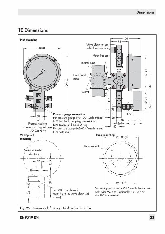
10Dimensions
Center of the in-dicator unit
15692
Ø16
8
147
55
Ø10
1
SW17
3726
ab26
43
200
117
25
+0.2
+5
- 0.3
5230 15
8.5
18
30
43.5
Ø180
Ø165
30˚30˚
Ø191
3160
297.
5
PressuregaugeconnectionFor pressure gauge NG 100 · Male thread G ½ B-LH with coupling sleeve G ½, DIN 16283 and 12x2 O-ringFor pressure gauge NG 63 · Female thread G ¼ with seal
Two Ø8.5 mm holes for fastening to the valve block (M8 screws)
Wall/panelmounting
Pipemounting
Panelmounting
Panel cut-out
Valve block for up-side down mounting
Mounting part
Vertical pipe
Horizontal pipe
Clamp
Process medium connection: Tapped hole
ISO 228 G 3/8
Six M4 tapped holes or Ø4.5 mm holes for hex bolts with M4 nuts. Optionally 3 x 120° or 4 x 90° can be used.
Fig. 25:Dimensional drawing · All dimensions in mm

34 EB9519EN

EB9519EN 35

SAMSON AG · MESS- UND REGELTECHNIKWeismüllerstraße 3 · 60314 Frankfurt am Main, GermanyPhone: +49 69 4009-0 · Fax: +49 69 [email protected] · www.samson.de EB 9519 EN 20
17-0
7-18
· En
glish