Embed Size (px)
Citation preview

DIFFERENTIAL MOVEMENT
in Platform Timber Frame
A UKTFA Special Project May 2008

A1M Ltd A1M Site Services Ltd Acacia Timber Construction Ltd Actis Insulation Ltd Advanced Timber Craft Ltd Alexander Timber Design Limited Andy Collett Associates Anglia Carpentry Contractors Ltd Arch Timber Protection BEA Fastening Systems Limited Bellwood Timber Frame Boise Engineering Wood Products Ltd Bristish Gypsum - Isover Ltd British Gymsum Ltd BSW Timber Plc Burnham Carpentry Contractors Ltd Cameron & Ross Canada Wood UK Cavalok Building Products Ltd CCB Evolution CCG (OSM) Ltd Christian Torsten Ltd Clancy Consulting Ltd Clyde Insulation Supplies Ltd Covers Timber Structures Ltd Crown Timber Plc Cullen Building Products Ltd Custom Homes DBM Consultants Deeside Timberframe Ltd Donaldson Timber Engineering Ltd Douglas Wm Standring Drumbow Timber Frame ECO Timber Frame Ltd Eleco Software Ltd Eleco Timber Frame Limited English Brothers Limited European Timber Systems Excel Industries Ltd Falcon Panel Products Ltd Fawcett Construction Finnforest UK Ltd Flemings Building Ltd Flight Timber Products Fforest Timber Engineering Ltd Frame Homes UK Ltd Frame Wise Ltd Gang-Nail Systems Ltd Genesis Timber Engineering Ltd Gibbs Timber Frame Ltd Glenalmond Timber Company Ltd Goodwins Timber Frame Grampian Construction Limited Guildford Timber Frame Ltd Harlow Bros Ltd Holbrook Timber Frame Limited Hunton Fiber (UK) Ltd Huntsman (Belgium) BVBA Ideal Lifts Ltd IJM Timber Frame Ltd
Page of Thanks J Danskin & Co Limited James Jones & Sons Ltd JJ Smith & Co (Woodworking Machinery) K Lue Carpentry Ltd Kingspan Insulation Ltd Klober Ltd Knauf Insulation Ltd Laing Homes Layton Blackham Insurance Brokers Leisureline Joinery Lewis Timber Frame Ltd M&M Timber Frame Maple Timber Frame of Langley Limited Marlows Timber Engineering Masterframe UK Limited Mitek Industries Ltd MTE (Leicester) Ltd Neatwood Homes Ltd New World Timber Frame Ltd Norbord Ltd Oakworth Homes Limited Pace Timber Systems Panel Agency (Masonite AB) Paslode Duo-fast Limited Pavlosvskis Lister PGM Carpentry Contractors Limited Pinewood Structures Ltd Poppers Senco UK Ltd Potton Ltd PPK Timber Designs Prestoplan Ltd Protim Solignum Puhos Board Randek BauTech AB Regal Carpentry Contractors Ltd Robertson Timberkit Rockwool Ltd Roe Timber Frame Ltd Rowlinson Constructions Limited RTC Timber Systems Rushmoor Engineering Services Ltd Scotframe Timber Engineering Ltd Sequoia Joinery Limited Seven Oaks Timber Engineering Ltd Silvatec Design Limited Simpson Strong-Tie S.J. Root & Co Ltd Solo Timber Frame Ltd Southern Timber Frame Stanley Bostitch Steico Limited Stewart Milne Timber Systems Ltd Strathclyde Timber Systems Ltd Swift Timber Homes Ltd Sydenhams Timber Engineering Ltd Taylor Lane Timber Frame Ltd The A Proctor Group The Border Design Centre The Design People (UK) Ltd Thomas Consulting Civil & Structure Engineers
Thomas Fleming Homes Ltd Thomas Mitchell Homes Ltd Timber Frameworks Ltd Timberframe Wales Ltd Timberlok Limited Trade Fabrication Systems Ltd Unibud SP zoo (Danwood House) Unitek Timber Frame Systems UPM Kymmerne Wood Ltd Walker Timber Ltd Wolf Systems Ltd Wyckham Blackwell Ltd Xella Dry Lining Systems Xtratherm UK Ltd Young Black Ltd

Page 1
UKTFA - Differential Movement Guidance
Document : Guidance on detailing junctions to accommodate differential movement in timber frame buildings Forward This document has been written by Ian Loughnane, Technical Director, Prestoplan and illustrated by CCB Evolution, timber frame consultants, as part of the UK Timber Frame Association’s initiative to promote good practice. The authors wish to thank the UKTFA Technical Committee for their oversight and contribution to the work. Project funding was provided by the UKTFA special project fund, NHBC and Wood for Good. This publication is referred to by the NHBC warranty manual and we would particularly like to thank Peter Crane of the NHBC for his encouragement and contribution to the project. The technical content was agreed by the UKTFA Technical Committee and thanks are given to all companies who have contributed to the document.

Page 2
UKTFA - Differential Movement Guidance
Contents
Ref Topic Page 1.0 Understanding the principles 3 2.0 Guidance on timber frame movement 7 2.1 Introduction and key to drawings 7 2.2 Joint Location – Windows 8 2.3 Joint Location – Roofline Eaves and Verge 15 2.4 Joint Location – Non Masonry Cladding 19 2.5 Joint Location – Balconies 23 2.6 Joint Location – Drive Through Details 29
2.7 Joint Location – Stairs & Common Areas with Timber Frame Surround 31
2.8 Joint Location – Concrete and Masonry Stairs / Common Areas with Timber Frame Surround 34
2.9 Joint Location – Lift shafts 37 2.10 Joint Location – Services 40 2.11 Joint Location – Chimneys and Masonry fireplaces 45 2.12 Joint Location – Existing Building Extensions 48
Page 3
UKTFA - Differential Movement Guidance
1.0 Understanding the Principles 1.1 Introduction Timber frame structures reduce in overall height during the first two years of use. This movement may affect other building elements unless properly constructed to cope with the resulting differential movement. This document provides a comprehensive overview of the locations to be considered based on many years experience. This publication does not provide joint details or technical fabrication drawings but rather guidance aimed at Architects and Builders to promote a better understanding of the principles to ensure that defects caused by lack of movement joints are avoided. 1.2 Background 1.2.1 Technical Basics Timber framed buildings reduce in overall height during the first two years of use. The magnitude of this movement will be calculated by the frame’s manufacturer. The following mechanisms, in order of magnitude, drive this characteristic:
• Reduction in the moisture content of the timber cross section (Up to
two years after hand over)
• Tightening up of joints under load (which is complete at the end of the construction period)
• Elastic shortening of compression members under load (which is a minor movement)

Page 4
UKTFA - Differential Movement Guidance
The diagram below illustrates the mechanism. The adjacent diagram shows the typical elements that may exist through an upper storey height section. The primary mechanism driving reduction in height is shrinkage of cross grain timber as moisture is driven out in use. From this it can be seen that the majority of movement occurs at the floor zone where the cross grain timber is concentrated. (Note: The vertical shortening down the length of timber in studs is negligible.) – refer to diagram 1.2.2. By the same token the secondary mechanism of joint tightening also occurs in the same region. Manufacturers can modify the degree of movement experienced by removing cross grain timber from the frame and utilising timbers of reduced initial moisture content. Builders can reduce the degree of settlement by tiling the roof or loading out floors before commencing external claddings.

Page 5
UKTFA - Differential Movement Guidance
Joint Tightening Locations
Cro
ss G
rain
S
hrin
kage
Diagram 1.2.2 – detail A2 – Cross Grain Shrinkage and junction interfaces where movement can take place

Page 6
UKTFA - Differential Movement Guidance
In the absence of specific data, the movement values for timber frame should be calculated using the following values in the table below:
Cross Sectional Frame material Movement allowance
20 % moisture content timber – standard timber 2.8 %
14 % moisture content timber – super dry timber and Glulam 1.2 %
10 % engineered wood products (e.g. laminated veneer lumber) 0.6%
NOTE 1 The depth of cross grain timber used in the above calculation should include all soleplates, rails, joist, and plates.
NOTE 2 Average moisture contents at the time of erection
NOTE 3 The designer’s attention is brought to the possible increased shortening caused by concentrated loads due to compression at junctions and elastic shortening
1.2.2 External Elevations The timber frame shrinkage occurs throughout the structure but it is typically differential movement to external cladding that requires specific attention in detailing. The behaviour of the cladding has also to be considered as this can increase the degree of movement experienced by the joint. For example, Steel sheet claddings expand and contract with temperature, clay masonry expands. The anticipated movement of cladding is to be added to the timber frame values for an overall joint movement figure. It is also common practice for movement joints to be sealed and because sealants cannot compress to zero the final constructed joint depth should be calculated as follows: Joint Size = Frame shrinkage + Cladding expansion + Minimum compressed sealant depth Joint sizes and positions will vary dependent on height of the frame and whether or not the cladding (internal or external) is fixed or independent of the structure.

Page 7
UKTFA - Differential Movement Guidance
2.0 Timber Frame Movement Guidance
2.1 Introduction and Key to drawings The following sections and drawings provide guidance on principles for construction detailing. Each section provides a topic with drawings illustrating the direction of movement. The drawings show the difference in levels from the time of build (referred to as “before”) to final level (referred to as “after”).
Key to Drawing Symbols M
Downward timber frame movement. Direction shown by the arrow.
BE Brick / cladding expansion – shown by the arrow as upward movement.
C.G. Initial Construction Gap – “before”
F.G. Final Gap – post-movement – “after”
O.G. Opened Gap – post-movement – “after”

Page 8
UKTFA - Differential Movement Guidance
2.2 Joint Location – Windows Windows are fixed to the timber frame and sit either within or just behind the external cladding. If the external cladding is supported independently of the timber frame, the vertical movement between the two components (window fixed to the timber frame and cladding) needs to be considered. A movement joint will be required on all four sides of an opening. Where the cladding is supported by the timber frame there is no differential vertical movement to consider other than any expansion or contraction of the cladding system. There are two common locations for windows or other similar units such as, doors to balconies.
In Scotland it is common to fix the window directly behind the masonry with an extended cill. The masonry reveals lap over the frame at the sides and the top leaving a physical joint gap at the base only. Elsewhere the window is pushed forward to sit within the masonry skin. In this instance movement joints need to be provided on all four sides. Special consideration needs to be given to full height glazing commonly seen on stair wells. The window frame must allow for the shortening of the building without becoming loaded. Often this is achieved by splitting the glazing into storey height units with a movement joint at each floor level.
Avoiding Problems 1. Use a sealing system that can cope with the movement1. 2. Ensure the joint is not compromised for example by mortar intrusion 3. Ensure window packing shims do not extend into the joint 4. Ensure that the joint is constructed to the right size. 5. Ensure that sufficient clearance is left on lintel clips2. 6. When laying masonry cladding it is essential to take account of soleplate
packing as this impacts on the distance from the splash course to the ground floor window and door head positions.
1Note the UKTFA does not recommend the use of silicone sealants in this situation 2 Note the limitations of clipped lintels to take movement - Masonry support lintels utilising clip restraints fixed to the frame are only suitable for low movement as the clearance gap between the clip and lintel closes up as movement takes place.

Page 9
UKTFA - Differential Movement Guidance
Diagram 2.2.a- WH1 Window Head junction with masonry cladding showing before and after vertical movement.

Page 10
UKTFA - Differential Movement Guidance
Diagram 2.2.b- WH2 Window Head junction with masonry cladding and propriety clipped lintel showing before and after vertical movement. Note: Clipped lintels are only suitable up to 3 storey timber frame
Diagram 2.2.c- WH3 Window Head junction with masonry cladding and steel angle masonry lintel showing before and after vertical movement.

Page 11
UKTFA - Differential Movement Guidance
Diagram 2.2.d – WH4 Window head junction with – lightweight cladding fixed to the timber frame. Showing no differential vertical movement before or after.
Diagram 2.2.e Ws1 Window cill level junction with lightweight cladding and no differential movement

Page 12
UKTFA - Differential Movement Guidance
Diagram 2.2.f Ws2 Window cill level junction with masonry cladding before and after

Page 13
UKTFA - Differential Movement Guidance
Diagram 2.2.g-WR1 Plan and elevation Window Reveal extended into the depth of the masonry cladding

Page 14
UKTFA - Differential Movement Guidance
Diagram 2.2.h- WR2 Plan and elevation Window Reveal extended into the depth of the masonry cladding
Page 15
UKTFA - Differential Movement Guidance
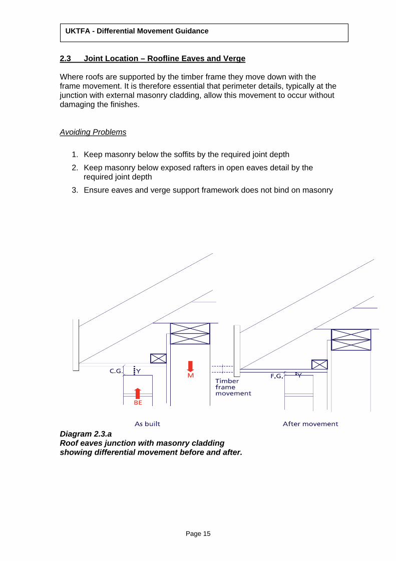
2.3 Joint Location – Roofline Eaves and Verge Where roofs are supported by the timber frame they move down with the frame movement. It is therefore essential that perimeter details, typically at the junction with external masonry cladding, allow this movement to occur without damaging the finishes. Avoiding Problems
1. Keep masonry below the soffits by the required joint depth 2. Keep masonry below exposed rafters in open eaves detail by the
required joint depth 3. Ensure eaves and verge support framework does not bind on masonry
Diagram 2.3.a Roof eaves junction with masonry cladding showing differential movement before and after.

UKTFA - Differential Movement Guidance
Page 16
Diagram 2.3.b Alternative roof eaves junction with masonry cladding showing differential movement directions.
Page 17
UKTFA - Differential Movement Guidance
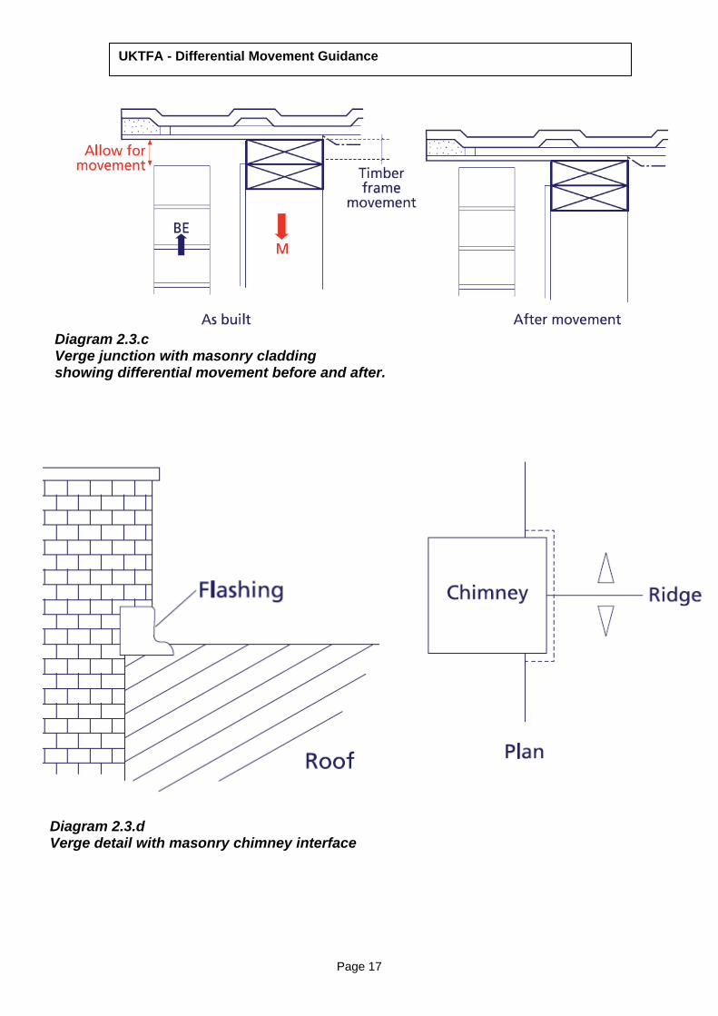
Diagram 2.3.c Verge junction with masonry cladding showing differential movement before and after.
Diagram 2.3.d Verge detail with masonry chimney interface

Page 18
UKTFA - Differential Movement Guidance
Diagram 2.3.e – refer to 2.3.d for location example Verge detail with masonry chimney showing options for flashing Note this guidance is for where a chimney is fully supported by masonry.

Page 19
UKTFA - Differential Movement Guidance
2.4 Joint Location – Non Masonry Cladding Where cladding is supported directly by the frame3 the majority of movement occurs at the floor zone. Joint sizing is therefore independent of the frame height and only the movement at each floor zone needs to be accommodated. Each joint is the same size and located at the floor zone. When forming these joints it is essential to consider the implications for fire barriers and cavity ventilation. Avoiding Problems 1. Ensure that the movement joint detailing includes the cladding support framing so that all elements of the cladding system can accommodate movement 2. Use a sealing system that can cope with the movement
3 Even if there is a cavity between the cladding and the frame this is still the case.

Page 20
UKTFA - Differential Movement Guidance
Diagram 2.4.a Junction at the floor zone with lightweight cladding supported by timber frame as built

Page 21
UKTFA - Differential Movement Guidance
Diagram 2.4.b Junction at the floor zone with lightweight cladding supported by timber frame. after movement

Page 22
UKTFA - Differential Movement Guidance
Diagram 2.4.c – C2 Junction of lightweight cladding to masonry lower wall. Showing movement between the as built and after movement.

Page 23
UKTFA - Differential Movement Guidance
2.5 Joint Location – Balconies The requirement for movement joints will be determined by the support arrangement for the balcony. Balconies are often independently supported but tied back to the floor zone of the frame to provide lateral stability. Inevitably these lateral fixings pass though the cladding zone and will move down with the frame. Movement joints are required below the ties to allow this to occur without unduly loading the connection. It should also be noted that the detailing of the connection itself should allow for differential movement / rotation. This often requires a pinned joint or slotted hole arrangement. Without such consideration excessive joint loading may lead to damage. Where balconies are both restrained laterally and vertically supported on the building side there will be some rotation of the balcony floor as the building shortens. This effect can be offset by presetting the balconies to allow for the anticipated shrinkage. It is not unusual to “split the difference” and initially set the balcony out of level to allow for 50% of the calculated frame shrinkage. This allows for the possibility that the frame will not shrink as much as predicted whilst minimising the in built fall4. For independently supported balconies the difference in level between the threshold and balcony level will vary as the movement occurs. Flashings and other associated details should take account of this. Avoiding Problems
1. Ensure that connection design allows any required movement 2. Ensure joints are constructed to the correct size 3. Ensure any designed in falls are constructed accurately
4 Full consideration should be given to the effect of any slopes on the drainage of the balcony

Page 24
UKTFA - Differential Movement Guidance
Diagram 2.5.a –B1 Vertically free standing balcony and masonry tied back to the timber frame for lateral support

Page 25
UKTFA - Differential Movement Guidance
Diagram 2.5.b – B1 detail Detail of lateral tie to timber frame showing movement directions between the frame and masonry with balcony drawn as the “before” movement stage.
Diagram 2.5.c – B1 detail Detail of lateral tie to timber frame showing final location of masonry to frame tie in the “after” movement stage.

Page 26
UKTFA - Differential Movement Guidance
Diagram 2.5.d Vertically free standing balcony and cladding supported to the timber frame. Balcony tied back to the timber frame for lateral support.

Page 27
UKTFA - Differential Movement Guidance
Diagram 2.5. e B 2 detail Detail of lateral tie to timber frame showing differential movement between the frame cladding and balcony structure “before” and “after” movement.
Page 28
UKTFA - Differential Movement Guidance
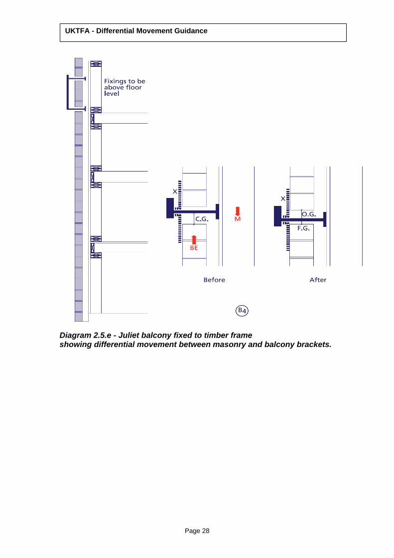
Diagram 2.5.e - Juliet balcony fixed to timber frame showing differential movement between masonry and balcony brackets.

Page 29
UKTFA - Differential Movement Guidance
2.6 Joint Location Drive-through Detail Building layouts sometimes require discontinuities of the timber frame structure at ground level, for example, at drive-throughs or where the frame bridges over other structures. Correct interface details are necessary to avoid damage at the point where timber frame meets the independent structure. At drive-throughs, for example, there is often the requirement for a masonry support over the opening. It is important that the masonry lintel is supported from the adjoining masonry, not the timber frame. Where the masonry support lintel takes lateral stability from the frame via clips on the top edge it is important that the clips leave a gap above the lintel edge to allow the frame and clip to move down.
Avoiding Problems
1. Ensure that any masonry built to the underside of floor above leaves a sufficient gap.
2. Ensure that any lintel clips allow sufficient gap above the top of the lintel
Diagram 2.6.a Isometric view of a drive through structure with masonry returning under the timber frame

Page 30
UKTFA - Differential Movement Guidance
Diagram 2.6.b – Section A- A Timber frame floor zone to drive through external lintel.
Diagram 2.6.c Section B-B Timber frame to the inner masonry lining to the drive through

Page 31
UKTFA - Differential Movement Guidance
2.7 Joint Location – Stairs & Common Areas with Timber Frame Surround Timber framed stair shafts are lined with plasterboard for the full height of the building. Without any allowance for movement this lining will buckle outwards as the building shortens. To avoid this movement joints are required at each floor level. These joints are often incorporated within an apron lining design to hide the joint. It is important that the apron lining fixing detail does not compromise the joints ability to compress.
Avoiding Problems
1. Apron linings over a joint should be fixed on one side only (above or below, not both)
2. Use pliable sealant / intumescent that can accommodate the movement
3. Ensure that the joint exists in both layers of plasterboard, not just the outer one.
4. Ensure that all the required joints are constructed 5. Avoid full height structural newels in buildings over two storeys. 6. Avoid full height stair newels that bridge floor to floor zones and there
by stop vertical movement across the floor zone

Page 32
UKTFA - Differential Movement Guidance
A
B
Diagram 2.7a A - Cross section through stair zone showing the areas where cross grain timber cause shortening B- Detail cross section through the plasterboard joint ( typically for buildings over 2 storeys in height)

Page 33
UKTFA - Differential Movement Guidance
Diagram 2.7b Cross section through stair zone showing where plasterboard can be subject to stresses.
Full
heig
ht o
f pla
ster
boar
d –
to
inco
rpor
ate
mov
emen
t joi
nts

Page 34
UKTFA - Differential Movement Guidance
2.8 Joint Location – Concrete and Masonry Stairs / Common Areas with Timber Frame Surround
In Scotland the building standards do not currently allow stair shafts, common areas or lift shafts to be constructed in timber. This means that in Scotland apartment buildings have masonry and concrete common areas as cores surrounded by timber frame apartments. The interface between the perimeter of the core and the surrounding apartments is a compartment wall consisting of two separate leaves, one of masonry and one of timber frame, with a cavity between. This cavity acts as the movement joint between the two areas. Apartment entrance doors and any junction with the surrounding roof needs appropriate detailing to avoid damage. Apartment entrance doors are located over the junction between the timber and masonry sections but only fixed to one side. The joint is hidden behind the architrave. To allow for the shortening it is common practice to set the timber finished floor 6mm above the common area floor and place a small fillet against the step to provide a smooth transition. This fillet is removed following the completion of the shortening process. This is normally a maximum of two years although most movement occurs within a year of occupation. The differential movement is also reflected at roof level. Roofs supported on the timber frame will move differentially to roofs supported by the masonry core. It is therefore important to detail the junction between the two with care. It is not uncommon for timber frame roof to be designed and detailed so that it clear spans over the masonry core without using the core for support. In these instances it is important to consider the preservation of fire integrity and allow sufficient clearance above the masonry core to allow the roof members to move down with the frame without fouling on the masonry5.
Avoiding Problems
1. Use a sealing system that can cope with the movement6. 2. Ensure joints are not compromised by mortar intrusion 3. Ensure that entrance door linings are only fixed to one leaf allowing
movement with the other leaf.
5 For lift shafts refer to the lift shaft section 6 Note the UKTFA does not recommend the use of silicone sealants in this situation

Page 35
UKTFA - Differential Movement Guidance
Diagram – 2.8 a – Timber frame junction with concrete/ masonry stair core as built showing transition structural deck to span across the two structural types.
Diagram – 2.8 b – Timber frame junction with concrete/ masonry stair core after movement showing transition structural deck.
Page 36
UKTFA - Differential Movement Guidance
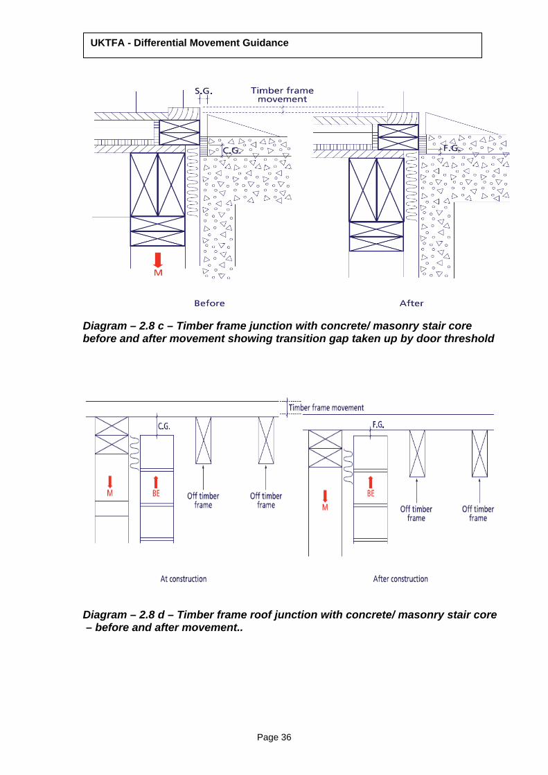
Diagram – 2.8 c – Timber frame junction with concrete/ masonry stair core before and after movement showing transition gap taken up by door threshold
Diagram – 2.8 d – Timber frame roof junction with concrete/ masonry stair core – before and after movement..

Page 37
UKTFA - Differential Movement Guidance
2.9 Joint Location – Lift shafts
Lift shafts will commonly consist of; a) A masonry or concrete shaft surrounded by timber frame with a small cavity. b) A lift manufacturer’s steel support shaft with lateral supports at floor level surrounded by timber frame. c) A set of lift car guides bolted back to a steel support laterally restrained
by the timber frame within a timber framed shaft. In each of these scenarios the structure carrying the lift car will not shorten with the frame. It is therefore essential to surround the shaft with timber frame including a cavity to act as a movement joint. The outer lift access doors are fixed to the timber frame. At each maintenance visit the lift engineer will recalibrate the lift to account for any differential movement across the lift threshold. It is particularly important that the top of the masonry / steel lift shaft does not become loaded by the shortening timber frame. Movement allowances need to be made in this area. (Refer to diagram 2.8d for example of detail.)
Avoiding Problems 1. Ensure outer lift access doors are only fixed to the timber frame wall. 2. Provide sufficient movement allowance between any steel support and the
timber frame. Where this detail consists of a slotted hole arrangement it is vital that the restraining bolts are fixed at the top of the slot to allow movement down with the frame. Consideration also needs to be given to methods of reducing friction loads that may frustrate the joint performance.
3. Provide sufficient allowance at the junction between the top of the shaft and independent roof structure to allow frame shortening to occur.

Page 38
UKTFA - Differential Movement Guidance
Diagram – 2.9a – Timber frame lift shaft – diagrammatic plan.
Diagram – 2.9b – Timber frame lift shaft to car frame junction it is essential that there is a sliding joint between the lift frame and the timber frame

Page 39
UKTFA - Differential Movement Guidance
Diagram – 2.9b – Masonry lift shaft with surrounding timber frame– it is essential that there is a joint to allow differential movement between the timber frame and masonry.

Page 40
UKTFA - Differential Movement Guidance
2.10 Joint Location – Services
It is not unusual for services to rise vertically for the full height of the building within a service shaft. Typical examples are soil vent pipes, cable trays and dry risers. These services must take account of the building shortening otherwise they will be damaged.
Soil Vent Pipes Soil vent pipes need to accommodate the movement in the surrounding frame. Rigid bracket supports should be avoided. In addition minimum waste pipe falls need to be increased to account for frame shrinkage. This is because the SVP will remain static (Movement being catered for by the brackets) whilst the appliance moves downward with the building therefore decreasing the originally constructed fall. Cable Risers Cable trays should not be continuous across the floor zone and where appropriate cables should be bent to allow the shortening in the cable run to be catered for. Wet & Dry Risers Rigid connections, for example within cast iron piping, are to be avoided. Any supporting trays or brackets must avoid loading pipework as the frame shortens. “Compression loops” may be required to control shortening in vertical runs.
Gas Distribution Similarly, attention is particularly drawn to services crossing from masonry built common areas into apartments within Scotland. Whilst the cavity within the party wall will move it is of particular importance that the service entry can also cope with the movement whilst preserving fire integrity.
Similar consideration is required where services pass through external cladding. For example, with masonry cladding it is important that a flexible junction is used across the cavity to avoid shearing the grille from the end of a ventilation duct.

Page 41
UKTFA - Differential Movement Guidance
Avoiding Problems
1. Provide additional falls for soil and waste pipe branches 2. Avoid rigid support brackets being used on soil vent pipes. Note:
Soil vent pipes have sheared off at the base with this fault.
3. Avoid rigid connection on wet and dry risers and design in movement details.
4. Provide gaps in cable trays to provide movement at floor levels.
Diagram – 2.10a – Diagrammatic view of the soil pipes incorrectly positioned at construction stage vertical pipes buckle and falls reduce as shortening occurs. The vertical pipes should have allowance for movement in the pipe joints (Refer Diagram 2.10 b)

Page 42
UKTFA - Differential Movement Guidance
Diagram – 2.10b – Diagrammatic view of vertical pipes with allowance for movement in the pipe joints.

UKTFA - Differential Movement Guidance
Page 43

Page 44
UKTFA - Differential Movement Guidance
Diagram – 2.10c – Diagrammatic view of Mechanical and Electrical service ducts showing allowance for vertical movement.
Diagram – 2.10d –Service pipes at junction with masonry cladding showing allowance for vertical movement.

Page 45
UKTFA - Differential Movement Guidance
2.11 Joint Location – Chimneys and Masonry fireplaces Typical Masonry chimneys cannot be supported by timber frame. There are three common solutions for the provision of chimney stacks. “False” chimneys Provided for aesthetic purposes these are commonly prefabricated “lightweight” units which can be supported by roof trusses or the timber frame. Where these units only interface with roof coverings no differential movement occurs. Chimneys located on gable ends must be entirely supported by the timber frame and a movement joint provided between the external masonry and the dummy chimney. For this reason it is usually a better solution to inset the chimney slightly to avoid this interface. “Hollow block” flues More commonly used within masonry housing it is possible to use these types of flue in timber frame. The timber frame is detailed with openings in the external wall which allow the blocks to be built in line with the wall. It is essential that all interfaces between the blockwork and the frame are built to allow the frame to shrink independently of the flue blocks. Particular care should be given to the fixing of internal finishes as these can distort when fixed directly to both frame and block. Masonry chimneys An alternative is to construct the flue / chimney entirely within the external masonry thereby preserving the cavity and the ability of the frame to move independently. Avoiding Problems
1. Ensure that any interface between blocks / masonry and the timber
frame allow for movement. 2. Ensure joints are not compromised by mortar intrusion 3. Use a sealing system that can cope with the movement7
7 Note the UKTFA does not recommend the use of silicone sealants in this situation

Page 46
UKTFA - Differential Movement Guidance
Diagram – 2.11 a–detail of the timber frame and masonry flue showing the joint for vertical movement.
Diagram – 2.11 b-Plan detail of the timber frame and masonry flue showing the joint for vertical movement.

Page 47
UKTFA - Differential Movement Guidance
Diagram – 2.11 c– consideration for the differential movement of lightweight chimneys supported off the timber frame.
Diagram – 2.11 d alternative support of lightweight chimney on truss roof.

Page 48
UKTFA - Differential Movement Guidance
2.12 Joint Location – Existing Building Extensions Where timber framed extensions are built onto an existing masonry building y or an older timber framed there needs to be a movement joint provided at the junction. The reason for the requirement against an existing timber framed building is that the new frame will move differentially against the existing frame that has completed the shortening cycle. Any link at floor level between the two buildings should be designed as a “drawbridge” that will allow rotation at each end without damage. If the link is not capable of being detailed as an independent structure then the junction needs to be made flexible. Hotels are a common example where a central corridor has rooms on either side. The new building floor level can be preset above the existing to account for the expected shortening. To avoid a step at floor level the corridor joists are turned round to span from the new build ONTO the existing structure over a distance of 2-3 metres. This means that the floor can rotate to allow the movement to take place without compromising the function of the building. To allow this detail to be implemented it is important that room access doors are kept clear of this area to avoid a secondary step at this junction. Additionally it is not good practice to try and line up roofs between new and old. The subsequent movement will show at eaves and ridge levels producing unsightly roof lines.
Avoiding Problems
1. Provide a timber frame end wall and cavity at the junction with the existing building to facilitate movement.
2. Design roofs with a break or parapet to hide any differential movement and don’t make eaves lines continuous across the joint
3. Use flashings to preserve weather tightness 4. Detail the structure to allow flexible links between the two buildings

Page 49
UKTFA - Differential Movement Guidance
Diagram – 2.12 a Junction of existing structure and new timber frame.

Page 50
UKTFA - Differential Movement Guidance
Diagram 2.12b Differential movement between timber frame and masonry/adjacent structure