Embed Size (px)
Citation preview

Differential-Mode EMI Reduction in a Multiphase DCM Flyback Converter
Pablo Zumel, Osear García, Jesús A. Oliver, and José A. Cobos,
Abstract—Switched converters are a source of electromagnetic interference (EMI) due to the hard switching and abrupt edges in the current and voltage waveforms. Multiphase converters can reduce the EMI at the source, minimizing the conducted EMI gen-eration, without changing dramatically the normal operation of the circuit. Input fllter can be greatly reduced, radiated EMI is lower, and internal EMI problems are minimized. This paper is focused on exploring multiphase converters as a topological technique to reduce conducted differential-mode EMI generation at the source, considering some nonidealities of the multiphase converter.
Index Terms—Electromagnetic conductive interference, power conversión, power conversión harmonics.
I. INTRODUCTION
SWITCH-MODE converters manage the energy in a pul-sating way but the use of interleaving technique [l]-[3]
provides a more continuous energy flow. From the point of view of conducted differential mode (DM) electromagnetic interference (EMI), interleaved operation is very interesting, since the bad EMI behavior of switched converters is in part due to the fact that the energy is taken from the main source abruptly at high frequencies.
Paralleling and shifting power converters, known as interleaving technique, have been used widely in the recent years [4]-[8]. The goal is increasing the effective frequency of the converter by synchronizing several smaller converters (basic cells or phases) and operating them with relative time shifts. The effect seen from outside the multiphase power converter is a converter with higher switching frequency (n times the switching frequency of a single phase) and less peak-to-peak ripple. In Fig. 1, two input current waveforms are shown: single-phase operation (single phase or no phase shifting between parallel converters) and interleaved operation (phase shifting between paralleled converters).
A signifleant reduction of the EMI fllter is expected based on the ripple cancellation effect and the rise of the effective ripple current (in theory proportional to the number of phases). This reduction yields to lower volume and weight what beneflts the power density of the converter.
Single phase eqw/slent Converter Input Current
Input Current
°0 2 4 6 8 10 "~12
Fig. 1. Input energy flow in a multiphase converter.
The problem of increasing the number of phases can be solved by digital control implementations [5]-[7], [9]—[12], where ad-ditional advantages can be taken to optimize the efflciency of the converter [6], the bandwidth of the control loop [7], or im-proving current balance between phases [11], [13].
Nevertheless, the impact of interleaving in EMI is not always beneflcial. Interleaving is used in [14] in a power factor correc-tion (PFC) application, and it is shown that a two-phase interleaved boost converter in continuous conduction mode (CCM), in spite of the ripple cancellation, cannot improve the size of the EMI fllter.
There are many techniques to minimize the EMI generation, someofthembasedon minimizingparasitic couplings [15], [16] and some others based on acting in the operation principie of the circuit [17], [18] (soft switching, random pulsewidth mod-ulation (PWM) generation, etc.). Multiphase converters can be considered as a topological approach to DM EMI reduction, without changing the operation principie of the converter, as introduced in [1], [14], [19], and [20].
This paper is focused on the analysis of differential conducted EMI noise reduction of constant duty eyele PFC multiphase converters for a high number of phases, taking into account nonidealities. The analysis is based on a flyback converter in discontinuous conduction mode (DCM) as a power factor corrector while minimizing the generation of conducted EMI by a proper operation (shifting) of the converter (see Fig. 2).
II. APPLICATION DESCRIPTION: DCM FLYBACK CONVERTER
WITH PFC
Electromagnetic compatibility (EMC) considerations are es-pecially important in the case of PFC converters, because they are connected to the ac mains. They must meet low-frequency regulations, up to 2 kHz, and high-frequeney (EMI) regula-tions, from 150 kHz. Low-frequency requirements are met by

DC side Input Voltage Shift Register
Fig. 2. Multiphase DCM flyback converter.
means of the converter control combined with a proper topology, matching the input current of the converter with the proper input current waveforms. The conducted EMIs generated by high-frequency operation are commonly rejected by means of EMI filters operating between the mains and the converter [21].
A flyback converter has been widely used for low-power and low-cost PFC providing simplicity, robustness, and isolation. However, the power range commonly suitable for this converter is relatively low (for example, 100-200 W). A flyback converter in DCM operation with constant duty cycle is a natural resistor emulator [22] with the input average current being proportional to the input voltage. However, it generates a high EMI content (due to the falling edge and rising slope of the discontinuous input current; see Fig. 2), which must be filtered in many cases.
Interleaving provides EMI reduction and higher output power capability, so a very simple topology such as DCM flyback can be used in a higher power range. However, paralleling without shifting increases not only the output current capability, but also the EMI emissions to be filtered.
On the other hand, interleaving acts at high-frequency level. This is why the output capacitor cannot be reduced by interleaving, because it is used for low-frequency energy storage.
A proper current sharing among phases is warranted by the topology, since in this case, the phase current is reset at every switching cycle due to the DCM operation. Therefore, the current mismatch due to component tolerances and different layout could be kept in an admissible valué without any additional current sharing mechanism.
Gate signáis for the phases should be quite similar to per-form a proper harmonic cancellation. Digital controllers based on specific hardware, such as field-programmable gate arrays (FPGAs), provide an easy way to genérate many signáis [5], [7], [9], [10], [24], while the accuracy is higher than analog controllers. In this converter, a digital shifter for the pulses has been designed (see Fig. 3), and implemented in a low-range
Main pulse
Clk
Phase 1
Phase 1
Phase 2
Phase 3
Phase 4
Phase 2 Phase 4
i i
Fig. 3. Multiphase pulse generation scheme.
programmable logic device. The control digital blocks have been described using very high speed integrated circuits hardware description language (VHDL).
III. INPUT CURRENT HARMONIC CANCELLATION
The main concept involved in this paper is the cancellation of input current harmonics by means of interleaving. In terms of Fourier series, the input current is expressed in (1), where fs is the frequency of the input current (switching frequency), n is the order of the harmonic, and cn is the coefficient of the harmonic of order n
i(t) n = + oo
(1)
Let us consider an M-phase dc-dc converter (constant input voltage, no input capacitor) operating without any shifting among phases (equivalent to a single phase) and with relative shifting between phases, i.e., operating with interleaving.
When the converter operates with interleaving, controller generates a time delay of the current of each phase equal to the switching period over the number of phases (uniform time shifting). This time delay produces a different angle delay for each harmonic. When the angle delay is the same for all harmonics, they are added and the resulting amplitude is larger. When the angle delay is different for each harmonic, the sum of all of them is equal to 0, and then, the harmonic cancellation is pro-duced [23]. This feature of interleaved operation is described in expressions (2)-(4), where cn_p is the harmonic of order n of the phase p, cn_totai is the harmonic of the total input current (sum of the current trough all phases), M in the number of phases, and p is the pth phase
c —c e-j27rpfr (2)
M - l M - l
Cn_total = £ Cn , -jZnpjb M = C n E ^'"^ <3> o-3^PW
p=Q p=Q
Cn - to ta l
Mcn, i f ^ e Z
o, M ^
(4)
In the ideal case, when M phases are used, the first harmonic of the input current has a frequency M times higher than the

dBu
100
80
60
40
20
i Single phase converter
010 phase interleaved converter
10w 1 0 '
Frequency (Hz)
Fig. 4. Ideal harmonio cancellation in a multiphase converter with ten phases.
Phase 1 ideal
Phase 1 actual
Fig. 5. Effect of a nonideal shifting in one phase.
switching frequency, and the amplitude is the same if all phases were not shifted. The first (M— 1) harmonics disappear. For higher order harmonics, there are only harmonics with an order múltiple of the number of phases, as shown in Fig. 4. For a ten-phase converter switching at 100 kHz, harmonics from 100 to 900 kHz are cancelled, and the first one takes place at 1 MHz, the next at 2 MHz, and so on. Ideally, the frequency envelope of the harmonic spectrum is the same for both multiphase and equivalent single-phase operation, but with interleaving, a lot of harmonics disappear.
IV. NONIDEALITIES
In order to evalúate the application of this technique in actual converters, several nonidealities must be considered, such as nonuniform pulse shifting, nonuniform phase current amplitude, and nonuniform duty cycle.
A. Nonuniform Pulse Shifting
It is caused by the different delays introduced by drivers, MOSFETs, and a nonideal phase shifter (see Fig. 5). The effect of this nonideality depends on the additional delay. In the case of an additional delay in a single phase, the perturbation is shown in Fig. 6, where Aa is the relative difference between the nominal phase shift and the actual phase shift. The influ-ence of this nonideality in terms of harmonics is given by the
rl t rl
A
\ At *'
\ i \ r
Perturbation
Fig. 6. Perturbation due to a nonideal shifting in one phase.
10B
Frequency (Hz)
Fig. 7. One phase is not properly shifted.
relative duration of the delay, as shown in Fig. 7. In expression (5), the harmonic of order n is given when phase q has a difference in time of At = A T / / , under the condition of the ideal phase shift for phase q, with Aa = ArM. The new coefficient cn-total has two different parts: one of them corresponding to the ideal situation and the other one corresponding to the effect of the described nonideality. The amplitude of the harmonic corresponding to this nonideality in the worst case is given in (6), where cn_\^ is the amplitude of the harmonic of the equivalent single-phase converter (all phases working without phase shifting). Note that for ten phases, the amplitude of the harmonic is five times (14 dB) less than that the amplitude of the harmonic in the equivalent single phase
/ Ideal
^n-total — Cn
Nonideality \ M-\
e - j 2 7 r n ^ e - j 2 7 r n A r _ ^ + V ^ e-j27rpfr
p=0
(5)
C n _ t o t a l = C n ( e - ^ ^ ( - l - l ) )
=> cn_totai = 2cn = n^ V— ^ Z. (6)
B. Nonuniform Phase Current Amplitude
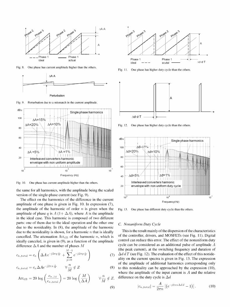
Due to the tolerance of inductors, there might be some vari-ations in the amplitude of the current waveforms through each phase, as shown in Fig. 8. The effect of nonuniform amplitude is
AA-A
Phase 1 ideal
Fig. 8. One phase has current amplitude higher than the others.
AA-A
Perturbation
Fig. 9. Perturbation due to a mismatch in the current amplitude.
dBu
100
so
60
40
AA=5%' X AA=1% I l i l i l í
Interleaved converters harmonic envelopewith non uniform amplitude
I I I l i l i l í 10 10
Frequency (Hz)
10
Fig. 10. One phase has current amplitude higher than the others.
the same for all harmonics, with the amplitude being the scaled versión of the single-phase current (see Fig. 9).
The effect on the harmonics of the difference in the current amplitude of one phase is given in Fig. 10. In expréssion (7), the amplitude of the harmonic of order n is given when the amplitude of phase q is A (1+ A A), where A is the amplitude in the ideal case. This harmonic is composed of two different parts: one of them due to the ideal operation and the other one due to the nonideality. In (8), the amplitude of the harmonic due to the nonideality is shown, for a harmonic n that is ideally cancelled. The attenuation AttdB of the harmonic n, which is ideally canceled, is given in (9), as a function of the amplitude difference A A and the number of phases M
/ M - l \
Cn_total =CnÍAAe j27Tq^ + ^ e
cn_total=cnAAe-^n^ V | ^ Z
-J2*PW
AttdB = 20 log ^n - to t a l
20 log / M \KA
(7)
(8)
M ^
Phase 1 ideal
Fig. 11. One phase has higher duty cycle than the others.
Ad-d-T
Ad-dT
Fig. 12. One phase has higher duty cycle than the others.
dBu
(9)
10
Frequency(Hz)
Fig. 13. One phase has different duty cycle than the others.
C. Nonuniform Duty Cycle
This is the result mainly of the dispersión of the characteristics of the controller, drivers, and MOSFETs (see Fig. 11). Digital control can reduce this error. The effect of the nonuniform duty cycle can be considered as an additional pulse of amplitude A (the peak current), at the switching frequency and duration of Ad d T (see Fig. 12). The evaluation of the effect of this nonideality on the current spectra is given in Fig. 13. The expression of the amplitude of additional harmonics corresponding only to this nonideality can be approached by the expression (10), where the amplitude of the input current is A and the relative difference on the duty cycle is Ad
|Cn_total| = ^ - | ( e - í 2 " ! A d d - l ) | . (10)

dBu
100
TABLEI SPECIFICATIONS OF THE DESIGNED CONVERTER
10
Frequency (Hz)
Fig. 14. Effect of nonidealities in the input current harmonic content. One phase is not properly shifted, has a current amplitude 1.3 higher than the others, and has 1.1 times the duty cycle.
The effects of all the aforementioned nonidealities are shown in Fig. 14. This is a worst-case estimation. In practice, all effects appear simultaneously with random distribution in all phases. One effect can act in the same way as another, and vice versa, two different effects can compénsate themselves.
In spite of the nonidealities, the effect of the interleaving is positive from the point of view of EMI. For relatively rough tolerances, the attenuation of the first harmonics can easily be higher than 30 dB. Additionally, it is possible to minimize the effect of those nonidealities by reordering the switching sequence of the phases [10].
Another nonideality is the interaction between the converter and the impedance seen from the input terminal of the converter, Le., EMI filter plus line impedance stabilization network (LISN). When the converter operates in interleaving, the interaction with EMI filter and LISN is not the same as that in single-phase operation, which is due to the fact that the converter presents different input impedance at high frequency in both cases.
V. SlMULATION AND EXPERIMENTAL RESULTS
In this section, simulation and experimental results are pre-sented in order to validate the theoretical predictions.
The number of phases (Le., ten) has been chosen in order to have a significant attenuation of the harmonics and a significant increase of the frequency of the first harmonic in the ideal case. With ten phases ideally, the first harmonic appears at ten times the original switching frequency, which is one decade higher. Moreover, the amplitude of this tenth harmonic is lower compared with the first.
In a real application, the number of phases should be chosen taking into account many design issues, such as efficiency, size, control complexity, and many others, including EMI.
Input AC Voltage
Output DC Voltage
Output Power max.
Switching Frequency
Number of Phases
110 Vac
48Vdc
150W
100 kHz
10
(b)
Fig. 15. Actual prototype. (a) Full view with control circuitry. (b) Power stage bottom view.
The power stage has the scheme shown in Fig. 2. The main specifications are shown in Table I. The control which has been implemented is a logic programmable device (complex pro-grammable logic device (CPLD), Xilinx XC-9500) shown in Fig. 15. The main pulse is generated by a PWM modulator and then the phase shifting is applied. One of the advantages of using DCM flyback topology for the multiphase converter is that it is not necessary to include any current sharing method. It only depends on the tolerances of the inductors and the duty cycle [25].
Simulated Differential Conducted EMI levéis
140
120
100
> 80
I 60 40
20
0
I I
WÉE
Ü Single Phase • Interleaved
TGl< Run: 10,0kS/s Hi Res E =F
100 200 300 400 500 600 700 800 900 1000
Frequency (KHz)
(a)
Simulated Differential Conducted EMI levéis
100 -i
1 MHz 2 MHz 3 MHz 4 MHz 5 MHz
(b)
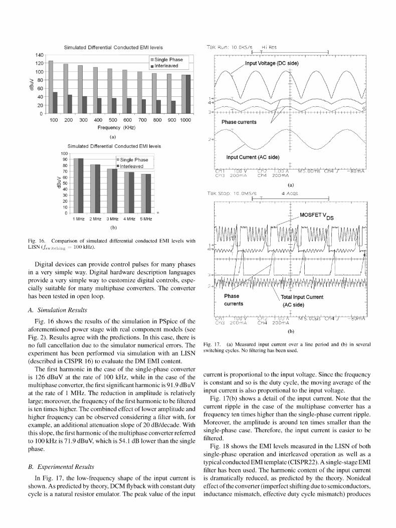
Fig. 16. Comparison of simulated differential conducted EMI levéis with LISN(/ s w i t c h i n g = 100kHz).
Digital devices can provide control pulses for many phases in a very simple way. Digital hardware description languages provide a very simple way to customize digital controls, espe-cially suitable for many multiphase converters. The converter has been tested in open loop.
A. Simulation Results
Fig. 16 shows the results of the simulation in PSpice of the aforementioned power stage with real component models (see Fig. 2). Results agree with the predictions. In this case, there is no full cancellation due to the simulator numerical errors. The experiment has been performed via simulation with an LISN (described in CISPR 16) to evalúate the DM EMI content.
The first harmonic in the case of the single-phase converter is 126 dBuV at the rate of 100 kHz, while in the case of the multiphase converter, the first significant harmonic is 91.9 dBuV at the rate of 1 MHz. The reduction in amplitude is relatively large; moreover, the frequency of the first harmonic to be filtered is ten times higher. The combined effect of lower amplitude and higher frequency can be observed considering a filter with, for example, an additional attenuation slope of 20 dB/decade. With this slope, the first harmonic of the multiphase converter referred to 100 kHz is 71.9 dBuV, which is 54.1 dB lower than the single phase.
B. Experimental Results
In Fig. 17, the low-frequency shape of the input current is shown. As predicted by theory, DCM flyback with constant duty cycle is a natural resistor emulator. The peak valué of the input
/Input Voltage (DC side)
Input Current (AC side)
L_ Chí ' ' 'l'üü V' ' ' 'C\\2 ' ' i.OO'Á' ' ' Mb'.üüms ch<4 J Ch3 200mA Ch4 2QGmA
TGI< s top: i O .DMS/S
-80mA
'Chi ' ' 1ÜÜ V Ch'A 1.UÜ A M Í .ÜÜMS Ch3 200mA Ch4 200mA
(b)
Fig. 17. (a) Measured input current over a line period and (b) in several switching cycles. No filtering has been used.
current is proportional to the input voltage. Since the frequency is constant and so is the duty cycle, the moving average of the input current is also proportional to the input voltage.
Fig. 17(b) shows a detail of the input current. Note that the current ripple in the case of the multiphase converter has a frequency ten times higher than the single-phase current ripple. Moreover, the amplitude is around ten times smaller than the single-phase case. Therefore, the input current is easier to be filtered.
Fig. 18 shows the EMI levéis measured in the LISN of both single-phase operation and interleaved operation as well as a typical conducted EMI témplate (CISPR22). A single-stage EMI filter has been used. The harmonic content of the input current is dramatically reduced, as predicted by the theory. Nonideal effect of the converter (imperfect shifting due to semiconductor s, inductance mismatch, effective duty cycle mismatch) produces

120
100
80
60
40
20
I I I ffl
L
— dBuV 1 Phase — CISPR 22 Témplate ~
l I ,
l i l i luí' '
0
10000 100000 1000000
Frequency
(a)
10000000 100000000
120
100
80
60
E < 40
20
CISPR 22 Témplate -dBuV 10 Phases
o 10000 100000 1000000 10000000 100000000
Frequency
(b)
Fig. 18. Actual EMI levéis measurements. (a) Single-phase operation with input EMI filter. (b) Multiphase operation with input EMI filter.
Experimental Measurements
41 dB
• 1 Phase
• 10 Phases
5 2 d B 67 dB 28 dB / 53dB_ I 41 dB
Harmonic Order
Fig. 19. Harmonic comparison.
the noncancellation of the harmonics nonmultiple of the number of phases, Le., fhere should only be harmonics at the rate of 10 x 100 kHz, 20 x 100 kHz, etc. In terms of attenuation (see Fig. 19), the flrst nine harmonics exhibit attenuation between 22 and 67 dB. The tenth harmonic should be similar but a relatively small difference can be observed (nonlinearities of EMI fllter, delays of the driving circuits, etc). Optimization of the power stage (layout, component repeatitivity) can improve this performance, thus providing higher attenuation.
Note that the required attenuation of the input fllter is signifl-cant with interleaving operation. It means that using an LC fllter, both the valúes of inductance and capacitance could be reduced signiflcantly. It yields a signiflcant saving in the EMI fllter.
VI. CONCLUSIÓN
Interleaving of converters can be considered as a topological solution to reduce DM EMI generation. The effect of the interleaving on DM EMI generation has been analyzed. The analysis in the frequency domain shows that interleaving provides harmonic cancellation and increasing of the existing harmonics without increasing of the switching frequency. From the EMI point of view, it means a dramatic reduction of the EMI fllter size.
Nonidealities of the multiphase converter, such as nonuniform shifting, nonuniform phase current amplitude, and nonuniform phase duty cycle, limit some of the advantages provided by interleaving, but, in general terms, they provide a signiflcant attenuation for the lowest order harmonics.
A ten-phase flyback converter has been simulated and built in order to verify the fheoretical predictions. A signiflcant reduction of the harmonic amplitude can be achieved by interleaving converters (between 22 and 67 dB for the flrst nine harmonics), while the switching frequency is not increased, as shown in the experimental measurements.
Generation of accurate shifted pulses can be implemented easily in standard digital devices, like FPGAs or CPLDs or standard CMOS technologies. The algorithms are simple and they can be described using hardware description languages, thus providing ease of design and flexibility.
REFERENCES
[1] B. A. Miwa, D. M. Otten, and M. E. Schlecht, "High efficiency power factor correction using interleaving techniques," in Proc. Appl. Power Electron. Conf. Expo. (APEC1992), Feb. 23-27, pp. 557-568.
[2] J. B. Klaassens, W. L. F. H. A. M. de Chateleux, and M. P. N. van Wesen-beeck, "Phase-staggering control of a series-resonant DC-DC converter with paralleled power modules," IEEE Trans. Power Electron., vol. 3, no. 2, pp. 164-173, Apr. 1988.
[3] A. M. Wu, X. Jinwen, D. Markovic, and S. R. Sanders, "Digital PWM control: Application in voltage regulation modules," in Proc. IEEE Power Electron. Spec. Conf. (PESC1999), Jun. 27-M. 1, vol. 1, pp. 77-83.
[4] J. Zhang, J.-S. Lai, R.-Y. Kim, and W. Yu, "High-power density design of a soft-switching high-power bidirectional dc-dc converter," IEEE Trans. Power Electron., vol. 22, no. 4, pp. 1145-1153, Jul. 2007.
[5] A. Peterchev, J. Xiao, and S. Sanders, "Architecture and IC implementa-tion of a digital VRM controller," IEEE Trans. Power Electron., vol. 18, no. 1, pp. 356-364, Jan. 2003.
[6] J. A. Qahouq, L. Huang, and D. Huard, "Efficiency-based auto-tuning of current sensing and sharing loops in multiphase converters," IEEE Trans. Power Electron., vol. 23, no. 2, pp. 1009-1013, Mar. 2008.
[7] S. Xiao, S. Qiu, G. Miller, T. X. Wu, and I. Batarseh, "Adaptive modu-lation control for multiple-phase voltage regulators," IEEE Trans. Power Electron., vol. 23, no. 1, pp. 495^199, Jan. 2008.
[8] P Barbosa, F. Canales, J. C. Crebier, and F. C. Lee, "Interleaved three-phase boost rectifiers operated in the discontinuous conduction mode: Analysis, design considerations and experimentation," IEEE Trans. Power Electron., vol. 16, no. 5, pp. 724-734, Sep. 2001.
[9] T. Carosa, R. Zane, and D. Maksimovic, "Scalable digital multiphase modulator," IEEE Trans. Power Electron., vol. 23, no. 4, pp. 2201-2205, Jul. 2008.
[10] O. Garcia, A. de Castro, P Zumel, and J. A. Cobos, "Digital-control-based solution to the effect of nonidealities of the inductors in multiphase converters," IEEE Trans. Power Electron., vol. 22, no. 6, pp. 2155-2163, Nov. 2007.

[11] G. Eirea and S. Sanders, "Phase current unbalance estimation in multi-phase buck converters," IEEE Trans. Power Electron., vol. 23, no. 1, pp. 137-143, Jan. 2008.
[12] R. Foley, R. Kavanagh, W. Marnane, and M. Egan, "Multiphase digital pulsewidth modulator," IEEE Trans. Power Electron., vol. 21, no. 3, pp. 842-846, May 2006.
[13] W. Huang, D. Clavette, G. Schuellein, M. Crowther, and J. Wallace, "System accuracy analysis of the multiphase voltage regulator module," IEEE Trans. Power Electron., vol. 22, no. 3, pp. 1019-1026, May 2007.
[14] C. W. M. Xu, E C. Lee, and L. Bing, "EMI study for the interleaved multi-channel PFC," in Proc. IEEE Power Electron. Spec. Conf. (PESC 2007), pp. 1336-1342.
[15] B. Carsten, "Avoiding the EMI accident," presented at the 14th Ann. IEEE Appl. Power Electron. Conf. Expo. (APEC), Dallas, TX, Mar. 14-18, 1999.
[16] A. J. Sinclair, J. A. Ferreira, and J. D. van Wyk, "A systematic study of EMI reduction by physical converter layout and suppressive circuits," in Proc. Int. Conf. Ind. Electron. Control, Instrum. (IECON), 1993, pp. 1059-1064.
[17] D. González, J. Balcells, A. Santolaria, J.-C. Le Bunetel, J. Gago, D. Magnon, and S. Brehaut, "Conducted EMI reduction in power converters by means of periodic switching frequency modulation," IEEE Trans. Power Electron., vol. 22, no. 6, pp. 2271-2281, Nov. 2007.
[18] O. Trescases, W. Guowen, A. Prodic, and W. Tung, "An EMI reduction technique for digitally controlled SMPS," IEEE Trans. Power Electron., vol. 22, no. 4, pp. 1560-1565, Jul. 2007.
[19] L. Huber, B. Irving, and M. Jovanovic, "Open-loop control methods for interleaved DCM/CCM boundary boost PFC converters," IEEE Trans. Power Electron., vol. 23, no. 4, pp. 1649-1657, Jul. 2008.
[20] B. Lu, "A novel control method for interleaved transition mode PFC," in Proc. IEEE Appl. Power Electron. Conf. Expo. (APEC 2008), pp. 697-701.
[21] F. Y. Shih, D. Y. Chen, Y.-P Wu, and Y.-T. Chen, "A procedure for designing EMI filters for AC line applications," IEEE Trans. Power Electron., vol. 11, no. 1, pp. 170-181, Jan. 1996.
[22] R. Erickson, M. Madigan, and S. Singer, "Design of a simple high-power-factor rectifier based on the flyback converter," in Proc. Appl. Power Electron. Conf. Expo. (APEC 1990), pp. 792-801.
[23] P Zumel, O. Garcia, J. A. Cobos, and J. Uceda, "EMI reduction by in-terleaving of power converters," in Proc. 19th Annu. IEEE Appl. Power Electron. Conf Expo. (APEC 2004), vol. 2, pp. 688-694.
[24] A. de Castro, P Zumel, O. Garcia, and T. Riesgo, "Digital control in multi-phase dc-dc converters," Eur. Power Electron. (EPE) J., vol. 13, no. 2, pp. 21-27, May 2003.
[25] O. Garcia, P. Zumel, A. de Castro, and J. A. Cobos, "Automotive DC-DC bidirectional converter made with many interleaved buck stages," IEEE Trans. Power Electron., vol. 21, no. 3, pp. 578-586, May 2006.
Pablo Zumel (M'07) received the B.S. degree in electrical engineering from the University of Burgos, Burgos, Spain, in 1995, the M.S. degree in electrical engineering from the Universidad Politécnica de Madrid, Madrid, Spain, in 1999, the M.S. degree from the Ecole Céntrale París, París, France, in 2000, and the Ph.D. degree from the Universidad Politécnica de Madrid, in 2005.
From 1999 to 2003, he was a Researcher in the División de Ingeniería Electrónica, Universidad Politécnica de Madrid. Since 2003, he has been with
the Departamento de Tecnología Electrónica, Universidad Carlos III de Madrid, Madrid, where he is currently an Assistant Professor. His current research inter-ests include multiphase dc-dc converters, magnetic integration, digital control in power electronics, and educational issues on power electronics.
Osear García (M'98) was born in Madrid, Spain, in 1968. He received the Masters and Doctoral de-grees in electronic engineering from the Universidad Politécnica de Madrid (UPM), Madrid, in 1992 and 1999, respectively.
He is currently an Associate Professor at the UPM. He has been involved in more than 40 research projeets. He has authored or coauthored more than 100 papers published in IEEE conferences and jour-nals. He holds five patents. His current research inter-ests include switching mode power supplies, power
factor correction, power architectures, and digital control applied to power electronics.
Dr. García received the UPM Research and Development Award for Faculty Less Than 35 Years of Age in 2003 and the UPM Innovation in Education in 2005. He is a member of the IEEE Power Electronics Society (PELS) Industrial Electronics Society (ÍES) Spanish Chapter.
Jesús A. Oliver (M'00) was born in Toledo, Spain, in 1972. He received the M.S. and Ph.D. degrees in electrical engineering from the Universidad Politécnica de Madrid, Madrid, Spain, in 1996 and 2007, respectively.
In 1996, he was a Visiting Scholar at Center for Power Electronics Systems (CPES). In 2000, he was a Summer Intern at GE R&D, Schenectady, NY Since 2001, he has been an Assistant Professor of electrical engineering at the Universidad Politécnica de Madrid, where he became an Associate Professor in
2007. He has authored or coauthored over 45 technical papers, and holds one patent. He has been actively involved in over 25 R&D projeets for companies in Europe, the U.S., and Australia. His current research interests include modeling and control of power electronics systems, fuel cell powered systems, and energy efficient design.
r jose A. Cobos (M'92) was born in Spain in 1965. He received the Masters and Doctoral degrees in electrical engineering from the Universidad Politécnica de Madrid (UPM), Madrid, Spain, in 1989 and 1994, respectively.
Since 2001, he has been a Professor at the UPM. He is involved in the field of power supply systems for telecom, aerospace, automotive, and medical applications. His current research interests include low output voltage, magnetic components, piezoelectric transformers, transcutaneous energy transfer, and dy-
namic power management. He has authored or coauthored over 200 technical papers, and holds three patents. He has been actively involved in 22 R&D projeets awarded with publie funding in competitive programs, and 42 direct contraets for research and development for different companies worldwide, including Alcatel, Indra, Siemens, Philips Hearing Implants, Crisa, Tecnobit, Sedecal, Premo, and Sener in Europe, Agere Systems, Enpirion, Ansoft, and General Electric in the U.S., and Cochlear in Australia.
Prof. Cobos cooperates regularly with the IEEE and other professional as-sociations. He is an Associate Editor of the IEEE TRANSACTIONS ON POWER ELECTRONICS. He received several awards, including the UPM Research and Development Award for Faculty Less Than 35 Years of Age and the Richard Bass Outstanding Young Power Electronics Award of the IEEE (2000). He is the Vice Dean of Studies of the Escuela Técnica Superior de Ingenieros Industriales (ETSII), UPM.